EP3166153B1 - Heat-dissipation device of led - Google Patents
Heat-dissipation device of led Download PDFInfo
- Publication number
- EP3166153B1 EP3166153B1 EP15815941.8A EP15815941A EP3166153B1 EP 3166153 B1 EP3166153 B1 EP 3166153B1 EP 15815941 A EP15815941 A EP 15815941A EP 3166153 B1 EP3166153 B1 EP 3166153B1
- Authority
- EP
- European Patent Office
- Prior art keywords
- heat
- heat conducting
- led
- air
- conducting material
- Prior art date
- Legal status (The legal status is an assumption and is not a legal conclusion. Google has not performed a legal analysis and makes no representation as to the accuracy of the status listed.)
- Active
Links
Images
Classifications
-
- F—MECHANICAL ENGINEERING; LIGHTING; HEATING; WEAPONS; BLASTING
- F21—LIGHTING
- F21V—FUNCTIONAL FEATURES OR DETAILS OF LIGHTING DEVICES OR SYSTEMS THEREOF; STRUCTURAL COMBINATIONS OF LIGHTING DEVICES WITH OTHER ARTICLES, NOT OTHERWISE PROVIDED FOR
- F21V29/00—Protecting lighting devices from thermal damage; Cooling or heating arrangements specially adapted for lighting devices or systems
- F21V29/50—Cooling arrangements
- F21V29/60—Cooling arrangements characterised by the use of a forced flow of gas, e.g. air
-
- H—ELECTRICITY
- H10—SEMICONDUCTOR DEVICES; ELECTRIC SOLID-STATE DEVICES NOT OTHERWISE PROVIDED FOR
- H10H—INORGANIC LIGHT-EMITTING SEMICONDUCTOR DEVICES HAVING POTENTIAL BARRIERS
- H10H20/00—Individual inorganic light-emitting semiconductor devices having potential barriers, e.g. light-emitting diodes [LED]
- H10H20/80—Constructional details
- H10H20/85—Packages
- H10H20/858—Means for heat extraction or cooling
- H10H20/8586—Means for heat extraction or cooling comprising fluids, e.g. heat-pipes
-
- F—MECHANICAL ENGINEERING; LIGHTING; HEATING; WEAPONS; BLASTING
- F21—LIGHTING
- F21V—FUNCTIONAL FEATURES OR DETAILS OF LIGHTING DEVICES OR SYSTEMS THEREOF; STRUCTURAL COMBINATIONS OF LIGHTING DEVICES WITH OTHER ARTICLES, NOT OTHERWISE PROVIDED FOR
- F21V29/00—Protecting lighting devices from thermal damage; Cooling or heating arrangements specially adapted for lighting devices or systems
- F21V29/50—Cooling arrangements
- F21V29/70—Cooling arrangements characterised by passive heat-dissipating elements, e.g. heat-sinks
-
- F—MECHANICAL ENGINEERING; LIGHTING; HEATING; WEAPONS; BLASTING
- F21—LIGHTING
- F21V—FUNCTIONAL FEATURES OR DETAILS OF LIGHTING DEVICES OR SYSTEMS THEREOF; STRUCTURAL COMBINATIONS OF LIGHTING DEVICES WITH OTHER ARTICLES, NOT OTHERWISE PROVIDED FOR
- F21V29/00—Protecting lighting devices from thermal damage; Cooling or heating arrangements specially adapted for lighting devices or systems
- F21V29/50—Cooling arrangements
- F21V29/70—Cooling arrangements characterised by passive heat-dissipating elements, e.g. heat-sinks
- F21V29/80—Cooling arrangements characterised by passive heat-dissipating elements, e.g. heat-sinks with pins or wires
-
- F—MECHANICAL ENGINEERING; LIGHTING; HEATING; WEAPONS; BLASTING
- F21—LIGHTING
- F21V—FUNCTIONAL FEATURES OR DETAILS OF LIGHTING DEVICES OR SYSTEMS THEREOF; STRUCTURAL COMBINATIONS OF LIGHTING DEVICES WITH OTHER ARTICLES, NOT OTHERWISE PROVIDED FOR
- F21V29/00—Protecting lighting devices from thermal damage; Cooling or heating arrangements specially adapted for lighting devices or systems
- F21V29/85—Protecting lighting devices from thermal damage; Cooling or heating arrangements specially adapted for lighting devices or systems characterised by the material
- F21V29/89—Metals
-
- H—ELECTRICITY
- H10—SEMICONDUCTOR DEVICES; ELECTRIC SOLID-STATE DEVICES NOT OTHERWISE PROVIDED FOR
- H10H—INORGANIC LIGHT-EMITTING SEMICONDUCTOR DEVICES HAVING POTENTIAL BARRIERS
- H10H20/00—Individual inorganic light-emitting semiconductor devices having potential barriers, e.g. light-emitting diodes [LED]
- H10H20/80—Constructional details
- H10H20/85—Packages
- H10H20/858—Means for heat extraction or cooling
-
- H—ELECTRICITY
- H10—SEMICONDUCTOR DEVICES; ELECTRIC SOLID-STATE DEVICES NOT OTHERWISE PROVIDED FOR
- H10H—INORGANIC LIGHT-EMITTING SEMICONDUCTOR DEVICES HAVING POTENTIAL BARRIERS
- H10H20/00—Individual inorganic light-emitting semiconductor devices having potential barriers, e.g. light-emitting diodes [LED]
- H10H20/80—Constructional details
- H10H20/85—Packages
- H10H20/858—Means for heat extraction or cooling
- H10H20/8581—Means for heat extraction or cooling characterised by their material
-
- H—ELECTRICITY
- H10—SEMICONDUCTOR DEVICES; ELECTRIC SOLID-STATE DEVICES NOT OTHERWISE PROVIDED FOR
- H10H—INORGANIC LIGHT-EMITTING SEMICONDUCTOR DEVICES HAVING POTENTIAL BARRIERS
- H10H20/00—Individual inorganic light-emitting semiconductor devices having potential barriers, e.g. light-emitting diodes [LED]
- H10H20/80—Constructional details
- H10H20/85—Packages
- H10H20/858—Means for heat extraction or cooling
- H10H20/8582—Means for heat extraction or cooling characterised by their shape
-
- H—ELECTRICITY
- H10—SEMICONDUCTOR DEVICES; ELECTRIC SOLID-STATE DEVICES NOT OTHERWISE PROVIDED FOR
- H10H—INORGANIC LIGHT-EMITTING SEMICONDUCTOR DEVICES HAVING POTENTIAL BARRIERS
- H10H20/00—Individual inorganic light-emitting semiconductor devices having potential barriers, e.g. light-emitting diodes [LED]
- H10H20/80—Constructional details
- H10H20/85—Packages
- H10H20/858—Means for heat extraction or cooling
- H10H20/8583—Means for heat extraction or cooling not being in contact with the bodies
-
- F—MECHANICAL ENGINEERING; LIGHTING; HEATING; WEAPONS; BLASTING
- F21—LIGHTING
- F21Y—INDEXING SCHEME ASSOCIATED WITH SUBCLASSES F21K, F21L, F21S and F21V, RELATING TO THE FORM OR THE KIND OF THE LIGHT SOURCES OR OF THE COLOUR OF THE LIGHT EMITTED
- F21Y2101/00—Point-like light sources
-
- F—MECHANICAL ENGINEERING; LIGHTING; HEATING; WEAPONS; BLASTING
- F21—LIGHTING
- F21Y—INDEXING SCHEME ASSOCIATED WITH SUBCLASSES F21K, F21L, F21S and F21V, RELATING TO THE FORM OR THE KIND OF THE LIGHT SOURCES OR OF THE COLOUR OF THE LIGHT EMITTED
- F21Y2115/00—Light-generating elements of semiconductor light sources
- F21Y2115/10—Light-emitting diodes [LED]
Definitions
- the present invention belongs to the field of lighting electrical appliance, and specifically relates to a heat-dissipation device of an LED (Light Emitting Diode).
- LED Light Emitting Diode
- the LED has a series of prominent advantages.
- the LED lighting industry is in a phase of explosive growth currently.
- the LED has higher luminous efficiency than other light sources, more than half of energy obtained by the LED from a power supply is still used for heating.
- a small LED chip always generates a lot of heat while emitting light, and the heat will directly influence the normal operation of the LED.
- the present radiator is increasingly large and heavy but with little effect. Therefore, the heat-dissipation problem of the LED has been a problem that must be preferentially considered.
- An aim of the present invention is to provide a heat-dissipation device of an LED.
- the weight and size of the heat-dissipation device of the LED can be reduced exponentially under the condition that a proper working temperature of the LED chip is ensured, and the ground insulation of the whole heat-dissipation device can also be ensured.
- a state of the art heat dissipation device is disclosed in EP2720265A1 .
- the present invention provides a heat-dissipation device of an LED.
- the device includes a large number of cylinders made of a heat conducting material.
- the diameters of the cylinders of the heat conducting material are less than 2mm, and the minimum diameter is more than 0.01mm; a heat-dissipation housing of an LED chip is contacted with one end of the cylinders made of the heat conducting material through the heat conducting material or in a direct manner, in order to heat the air around the cylinders, and the heat is taken away by the flowing air.
- the diameters of the cylinders of the heat conducting material are less than 0.3mm, so that the cylinders made of the heat conducting material form one or a plurality of heat conducting material wires; the heat-dissipation housing of the LED chip is contacted with one end of the heat conducting material wires through the heat conducting material or in a direct manner, in order to transmit the heat to the heat conducting material wires and heat the air around the heat conducting material wires; and the heat is taken away by the flowing air.
- the heat-dissipation housing of the LED chip can be directly fused with one end of the heat conducting material wires into a whole; the LED chip directly heats the air around the heat conducting material wires through the heat conducting material wires on the heat-dissipation housing thereof, and the heat is taken away by the flowing air.
- the heat conducting material may be copper; the cylinders of the heat conducting material are copper cylinders, and the heat conducting material wires are copper wires.
- the surfaces of the cylinders of the heat conducting material or the heat conducting material wires can be covered by a protective layer for preventing the cylinders of the heat conducting material or the heat conducting material wires from being oxidized, corroded or polluted.
- the protective layer covering the surfaces can be a silver plating
- the cylinders of the heat conducting material, covered by the protective layer on the surfaces are silvered copper cylinders
- the heat conducting material wires covered by the protective layer on the surfaces are silvered copper wires.
- the cylinders of the heat conducting material or the heat conducting material wires are arranged in an air flowing pipeline; a blower is connected into the pipeline, and air is circulated by means of the blower to take away heat.
- the heat-dissipation device of the LED provided by the present invention may not be connected with the blower, while the cylinders of the heat conducting material or the heat conducting material wires are arranged in an air-flowing pipeline of which the outlet and the inlet have a certain height difference, air becomes light by means of heating expansion to form a pressure difference between the outlet and the inlet, and the air circulation is promoted to take away heat.
- the device may also include a special air-flowing pipeline for storing the heated air; the outlet and the inlet of the special air-flowing pipeline have a certain height difference, air becomes light by means of heating expansion to form a pressure difference, and the air circulation is accelerated to take away heat.
- a special air-flowing pipeline for storing the heated air; the outlet and the inlet of the special air-flowing pipeline have a certain height difference, air becomes light by means of heating expansion to form a pressure difference, and the air circulation is accelerated to take away heat.
- the pipeline may be made of an insulation material, in order to ensure the ground insulation of the whole heat-dissipation device.
- the area of the cylindrical surface is inversely proportional to the radius.
- the surface area of a copper wire having the diameter of 0.1m is 100 times the lateral surface of a copper cylinder having the same volume and the diameter of 1cm.
- the weight and size of the heat-dissipation device of the LED can be reduced exponentially under the condition that a proper working temperature of the LED chip is ensured, and the ground insulation of the whole heat-dissipation device can also be ensured. This is a fundamental change for the heat-dissipation device of the LED.
- a plurality of copper wires are directly welded on a heat-dissipation housing of an LED chip.
- the heat-dissipation housing transmits heat to the copper wires, in order to heat the air around the copper wires; and the heat is taken away by the flowing air.
- the surfaces of the copper wires are covered by a protective layer for preventing the cylinders of the heat conducting material from being oxidized, corroded or polluted.
- the heat-dissipation housing of the LED chip can be directly fused with one end of the copper wires into a whole.
- a plurality of LED chips welded with a plurality of copper wires are integrated together, and are properly arranged in an air-flowing plastic pipeline.
- the outlet and the inlet of the plastic pipeline have a certain height difference, air becomes light by means of heating expansion to further form a pressure difference, and air circulation is promoted to take away heat.
- the pipeline is made of an insulation material, in order to ensure the ground insulation of the whole heat-dissipation device.
- the LED chips are properly connected with each other and are connected to a proper driving power supply to form an LED lamp as we need.
- heat-dissipation device of the LED provided by the present invention, aluminum profiles which are usually large and heavy are changed into some metal wires arranged in the plastic pipeline, so that the weight and size of the heat-dissipation device of the LED can be reduced exponentially under the condition that a proper working temperature of the LED chip is ensured, and the ground insulation of the whole heat-dissipation device can also be ensured.
Landscapes
- Engineering & Computer Science (AREA)
- General Engineering & Computer Science (AREA)
- Led Device Packages (AREA)
- Cooling Or The Like Of Semiconductors Or Solid State Devices (AREA)
- Arrangement Of Elements, Cooling, Sealing, Or The Like Of Lighting Devices (AREA)
Description
- The present invention belongs to the field of lighting electrical appliance, and specifically relates to a heat-dissipation device of an LED (Light Emitting Diode).
- As green lighting, the LED has a series of prominent advantages. The LED lighting industry is in a phase of explosive growth currently.
- As we see, although the LED has higher luminous efficiency than other light sources, more than half of energy obtained by the LED from a power supply is still used for heating. For the LED, a small LED chip always generates a lot of heat while emitting light, and the heat will directly influence the normal operation of the LED.
- With the increase of the LED power, in order to increase the heat-dissipation surface area of a radiator, the present radiator is increasingly large and heavy but with little effect. Therefore, the heat-dissipation problem of the LED has been a problem that must be preferentially considered.
- An aim of the present invention is to provide a heat-dissipation device of an LED. The weight and size of the heat-dissipation device of the LED can be reduced exponentially under the condition that a proper working temperature of the LED chip is ensured, and the ground insulation of the whole heat-dissipation device can also be ensured. A state of the art heat dissipation device is disclosed in
EP2720265A1 . - The present invention provides a heat-dissipation device of an LED. The device includes a large number of cylinders made of a heat conducting material. The diameters of the cylinders of the heat conducting material are less than 2mm, and the minimum diameter is more than 0.01mm; a heat-dissipation housing of an LED chip is contacted with one end of the cylinders made of the heat conducting material through the heat conducting material or in a direct manner, in order to heat the air around the cylinders, and the heat is taken away by the flowing air.
- In the heat-dissipation device of the LED provided by the present invention, the diameters of the cylinders of the heat conducting material are less than 0.3mm, so that the cylinders made of the heat conducting material form one or a plurality of heat conducting material wires; the heat-dissipation housing of the LED chip is contacted with one end of the heat conducting material wires through the heat conducting material or in a direct manner, in order to transmit the heat to the heat conducting material wires and heat the air around the heat conducting material wires; and the heat is taken away by the flowing air.
- Further, the heat-dissipation housing of the LED chip can be directly fused with one end of the heat conducting material wires into a whole; the LED chip directly heats the air around the heat conducting material wires through the heat conducting material wires on the heat-dissipation housing thereof, and the heat is taken away by the flowing air.
- Herein, the heat conducting material may be copper; the cylinders of the heat conducting material are copper cylinders, and the heat conducting material wires are copper wires.
- The surfaces of the cylinders of the heat conducting material or the heat conducting material wires can be covered by a protective layer for preventing the cylinders of the heat conducting material or the heat conducting material wires from being oxidized, corroded or polluted.
- Specifically, the protective layer covering the surfaces can be a silver plating, the cylinders of the heat conducting material, covered by the protective layer on the surfaces, are silvered copper cylinders, and the heat conducting material wires covered by the protective layer on the surfaces are silvered copper wires.
- In the heat-dissipation device of the LED provided by the present invention, the cylinders of the heat conducting material or the heat conducting material wires are arranged in an air flowing pipeline; a blower is connected into the pipeline, and air is circulated by means of the blower to take away heat.
- The heat-dissipation device of the LED provided by the present invention may not be connected with the blower, while the cylinders of the heat conducting material or the heat conducting material wires are arranged in an air-flowing pipeline of which the outlet and the inlet have a certain height difference, air becomes light by means of heating expansion to form a pressure difference between the outlet and the inlet, and the air circulation is promoted to take away heat.
- Further, the device may also include a special air-flowing pipeline for storing the heated air; the outlet and the inlet of the special air-flowing pipeline have a certain height difference, air becomes light by means of heating expansion to form a pressure difference, and the air circulation is accelerated to take away heat.
- The pipeline may be made of an insulation material, in order to ensure the ground insulation of the whole heat-dissipation device.
- In the heat-dissipation device of the LED provided by the present invention, aluminum profiles which are usually large and heavy are changed into some metal wires arranged in the plastic pipeline, and the heat-dissipation effect of these metal wires is not hard to see through the following simple calculation. As we know, for a cylinder having a radius of r and a height of h, its volume is as follows:


- Thus, for the cylinder with the same volume, the area of the cylindrical surface is inversely proportional to the radius. In this case, the surface area of a copper wire having the diameter of 0.1m is 100 times the lateral surface of a copper cylinder having the same volume and the diameter of 1cm.
- Accordingly, a sufficient heat-dissipation area can be obtained with only a small amount of copper wires. In this case, the weight and size of the heat-dissipation device of the LED can be reduced exponentially under the condition that a proper working temperature of the LED chip is ensured, and the ground insulation of the whole heat-dissipation device can also be ensured. This is a fundamental change for the heat-dissipation device of the LED.
-
-
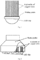
Fig. 1 shows an LED chip and a plurality of copper wires welded on a heat-dissipation housing of the LED chip in the present invention. -
Fig. 2 is a schematic diagram of a heat-dissipation device of an LED. - As shown in
Fig. 1 , as a beam of heat conducting material wires, a plurality of copper wires are directly welded on a heat-dissipation housing of an LED chip. The heat-dissipation housing transmits heat to the copper wires, in order to heat the air around the copper wires; and the heat is taken away by the flowing air. - The surfaces of the copper wires are covered by a protective layer for preventing the cylinders of the heat conducting material from being oxidized, corroded or polluted.
- The heat-dissipation housing of the LED chip can be directly fused with one end of the copper wires into a whole.
- As shown in
Fig. 2 , a plurality of LED chips welded with a plurality of copper wires are integrated together, and are properly arranged in an air-flowing plastic pipeline. - The outlet and the inlet of the plastic pipeline have a certain height difference, air becomes light by means of heating expansion to further form a pressure difference, and air circulation is promoted to take away heat.
- The pipeline is made of an insulation material, in order to ensure the ground insulation of the whole heat-dissipation device.
- The LED chips are properly connected with each other and are connected to a proper driving power supply to form an LED lamp as we need.
- In the heat-dissipation device of the LED provided by the present invention, aluminum profiles which are usually large and heavy are changed into some metal wires arranged in the plastic pipeline, so that the weight and size of the heat-dissipation device of the LED can be reduced exponentially under the condition that a proper working temperature of the LED chip is ensured, and the ground insulation of the whole heat-dissipation device can also be ensured.
Claims (9)
- A heat-dissipation device of an LED, wherein the device comprises a plurality of heat conducting wires,
and a heat-dissipation housing of the LED chip is contacted with one end of the plurality of heat conducting wires, in order to transmit heat to the heat conducting wires and heat the air around the heat conducting wires, so that the heat can be taken away by flowing air,
characterized in that
each heat conducting wire is formed by several cylinders made of a heat conducting material, wherein the heat-dissipation housing of the LED chip is contacted with one end of the cylinders made of the heat conducting material through the heat conducting material or in a direct manner, in order to heat the air around the cylinders, and the heat is taken away by the flowing air, wherein the diameters of the cylinders of the heat conducting material are more than 0.01 mm and less than 0.3 mm. - The heat-dissipation device of the LED of claim 1, wherein the heat-dissipation housing of the LED chip is directly fused with one end of the heat conducting wires; the LED chip directly heats the air around the heat conducting wires through the heat conducting wires on the heat-dissipation housing thereof, and the heat is taken away by the flowing air.
- The heat-dissipation device of the LED of claims 1 or 2, wherein the heat conducting material is copper; the cylinders of the heat conducting material are copper cylinders.
- The heat-dissipation device of the LED of any one of claims 1 to 3, wherein the surfaces of the cylinders of the heat conducting material are covered by a protective layer for preventing the cylinders of the heat conducting material from being oxidized, corroded or polluted.
- The heat-dissipation device of the LED of claim 4, wherein the protective layer covering the surfaces is a silver plating, the cylinders of the heat conducting material, covered by the protective layer on the surfaces, are silvered copper cylinders.
- The heat-dissipation device of the LED of any one of claims 1 to 5, wherein the heat conducting material wires are arranged in an air-flowing pipeline; a blower is connected into the pipeline, and air is circulated by means of the blower to take away heat.
- The heat-dissipation device of the LED of any one of claims 1 to 5, wherein the heat conducting material wires are arranged in an air-flowing pipeline; the outlet and the inlet of the pipeline have a certain height difference, air becomes light by means of heating expansion to form a pressure difference between the outlet and the inlet, and air circulation is promoted to take away heat.
- The heat-dissipation device of the LED of claim 7, wherein the device further comprises a special air-flowing pipeline for storing the heated air; the outlet and the inlet of the special air flowing pipeline have a certain height difference, air becomes light by means of heating expansion to form a pressure difference, and air circulation is accelerated to take away heat.
- The heat-dissipation device of the LED of any one of claims 6 to 8, wherein the pipeline is made of an insulation material, in order to ensure the insulation of the whole heat-dissipation device against ground.
Applications Claiming Priority (2)
| Application Number | Priority Date | Filing Date | Title |
|---|---|---|---|
| CN201410317415.1A CN104124331A (en) | 2014-07-04 | 2014-07-04 | Radiating device of LED |
| PCT/CN2015/083294 WO2016000662A1 (en) | 2014-07-04 | 2015-07-03 | Heat-dissipation device of led |
Publications (3)
| Publication Number | Publication Date |
|---|---|
| EP3166153A4 EP3166153A4 (en) | 2017-05-10 |
| EP3166153A1 EP3166153A1 (en) | 2017-05-10 |
| EP3166153B1 true EP3166153B1 (en) | 2018-10-24 |
Family
ID=51769672
Family Applications (1)
| Application Number | Title | Priority Date | Filing Date |
|---|---|---|---|
| EP15815941.8A Active EP3166153B1 (en) | 2014-07-04 | 2015-07-03 | Heat-dissipation device of led |
Country Status (6)
| Country | Link |
|---|---|
| US (1) | US20170162772A1 (en) |
| EP (1) | EP3166153B1 (en) |
| JP (1) | JP6587641B2 (en) |
| KR (1) | KR101938466B1 (en) |
| CN (1) | CN104124331A (en) |
| WO (1) | WO2016000662A1 (en) |
Families Citing this family (5)
| Publication number | Priority date | Publication date | Assignee | Title |
|---|---|---|---|---|
| CN104124331A (en) * | 2014-07-04 | 2014-10-29 | 张逸兴 | Radiating device of LED |
| CN104643899B (en) * | 2015-03-09 | 2018-02-23 | 王德普 | Kitchen range composition and application thereof |
| US11085626B2 (en) | 2015-09-17 | 2021-08-10 | Yixing ZHANG | Apparatus for heat exchange by using braided fabric woven from thermally conductive wire material |
| CN105114920A (en) * | 2015-09-17 | 2015-12-02 | 张逸兴 | Device capable of exchanging heat by using heat conduction material wire rod braided fabric |
| CN106195951A (en) * | 2016-08-24 | 2016-12-07 | 佛山市南海领上照明有限公司 | Radiator |
Family Cites Families (30)
| Publication number | Priority date | Publication date | Assignee | Title |
|---|---|---|---|---|
| JPS512727Y2 (en) * | 1971-03-22 | 1976-01-27 | ||
| US5083194A (en) * | 1990-01-16 | 1992-01-21 | Cray Research, Inc. | Air jet impingement on miniature pin-fin heat sinks for cooling electronic components |
| JP3692437B2 (en) * | 1997-05-21 | 2005-09-07 | 昭和電工株式会社 | Heat sink manufacturing method |
| CN1316608C (en) * | 2004-02-13 | 2007-05-16 | 上海三思科技发展有限公司 | A heat radiation needle arrangement for improving LED temperature rise |
| JP4221353B2 (en) * | 2004-11-19 | 2009-02-12 | Necディスプレイソリューションズ株式会社 | Light source device and projection display device |
| JP4872296B2 (en) * | 2005-09-30 | 2012-02-08 | 日亜化学工業株式会社 | Silicone rubber-sealed light emitting device and method for manufacturing the light emitting device |
| JP2008053564A (en) * | 2006-08-25 | 2008-03-06 | Matsushita Electric Ind Co Ltd | Optical semiconductor device and manufacturing method thereof |
| CN100572908C (en) * | 2006-11-17 | 2009-12-23 | 富准精密工业(深圳)有限公司 | Led lamp |
| CN101349519A (en) * | 2007-07-18 | 2009-01-21 | 富准精密工业(深圳)有限公司 | Hot pipe |
| JP5207681B2 (en) * | 2007-07-27 | 2013-06-12 | キヤノン株式会社 | Image projection apparatus and image display system |
| US7628522B2 (en) * | 2007-12-29 | 2009-12-08 | Fu Zhun Precision Industry (Shen Zhen) Co., Ltd. | Light emitting diode lamp |
| CN201277525Y (en) * | 2008-08-08 | 2009-07-22 | 龙国庆 | High-power LED lamp radiator with heat pipe function |
| WO2010010495A1 (en) * | 2008-07-25 | 2010-01-28 | Koninklijke Philips Electronics N.V. | A cooling device for cooling a semiconductor die |
| JP2010082636A (en) * | 2008-09-30 | 2010-04-15 | Allied Material Corp | Welding method of pillar-like member, method of manufacturing heat radiation member, and heat radiation member |
| JP4813582B2 (en) * | 2009-01-30 | 2011-11-09 | 株式会社 近藤工芸 | LED lamp |
| US20110110095A1 (en) * | 2009-10-09 | 2011-05-12 | Intematix Corporation | Solid-state lamps with passive cooling |
| JP2011155117A (en) * | 2010-01-27 | 2011-08-11 | Fdk Corp | Heat dissipation structure of coil |
| US9810418B2 (en) * | 2010-08-12 | 2017-11-07 | Micron Technology, Inc. | Solid state lights with cooling structures |
| US8858040B2 (en) * | 2010-08-23 | 2014-10-14 | Cooliance, Inc. | Cooling methodology for high brightness light emitting diodes |
| US8415704B2 (en) | 2010-09-22 | 2013-04-09 | Ut-Battelle, Llc | Close-packed array of light emitting devices |
| KR101789825B1 (en) * | 2011-04-20 | 2017-11-20 | 엘지이노텍 주식회사 | The light emitting device package having UV light emitting diode |
| JP5756332B2 (en) * | 2011-04-26 | 2015-07-29 | 住友精密工業株式会社 | heatsink |
| CN102252300A (en) * | 2011-07-05 | 2011-11-23 | 广州光为照明科技有限公司 | Novel heat dissipation light emitting diode (LED) street lamp module radiator |
| US8746915B2 (en) * | 2011-07-29 | 2014-06-10 | Cree, Inc. | Light emitting die (LED) lamps, heat sinks and related methods |
| US20130062656A1 (en) * | 2011-09-13 | 2013-03-14 | Inpaq Technology Co., Ltd. | Thermally enhanced optical package |
| CN103574547A (en) * | 2012-07-18 | 2014-02-12 | 欧司朗股份有限公司 | Cooling device manufacturing method, cooling device and lighting device |
| EP2720265A1 (en) * | 2012-10-12 | 2014-04-16 | IDEA Korb AG | Cooling body for light-emitting diode array |
| FR3004787B1 (en) * | 2013-04-19 | 2017-09-08 | Valeo Vision | COOLING DEVICE AND LIGHTING OR SIGNALING DEVICE FOR A MOTOR VEHICLE COMPRISING SUCH AN ORGAN |
| US9374904B2 (en) * | 2014-01-10 | 2016-06-21 | i2C Solutions, LLC | Thermal ground planes and light-emitting diodes |
| CN104124331A (en) * | 2014-07-04 | 2014-10-29 | 张逸兴 | Radiating device of LED |
-
2014
- 2014-07-04 CN CN201410317415.1A patent/CN104124331A/en active Pending
-
2015
- 2015-07-03 JP JP2016576040A patent/JP6587641B2/en active Active
- 2015-07-03 WO PCT/CN2015/083294 patent/WO2016000662A1/en not_active Ceased
- 2015-07-03 EP EP15815941.8A patent/EP3166153B1/en active Active
- 2015-07-03 KR KR1020167036876A patent/KR101938466B1/en active Active
- 2015-07-03 US US15/320,837 patent/US20170162772A1/en not_active Abandoned
Non-Patent Citations (1)
| Title |
|---|
| None * |
Also Published As
| Publication number | Publication date |
|---|---|
| JP6587641B2 (en) | 2019-10-09 |
| KR20170013346A (en) | 2017-02-06 |
| US20170162772A1 (en) | 2017-06-08 |
| WO2016000662A1 (en) | 2016-01-07 |
| CN104124331A (en) | 2014-10-29 |
| EP3166153A4 (en) | 2017-05-10 |
| JP2017521863A (en) | 2017-08-03 |
| KR101938466B1 (en) | 2019-01-14 |
| EP3166153A1 (en) | 2017-05-10 |
Similar Documents
| Publication | Publication Date | Title |
|---|---|---|
| EP3166153A1 (en) | Heat-dissipation device of led | |
| CN101806441A (en) | Large-power LED lamp heat radiator with fins having functions of heat pipes | |
| JP2019525391A5 (en) | ||
| CN102313180A (en) | Light emitting diode (LED) lamp with active heat radiation function | |
| CN104197292A (en) | Novel high-power LED radiating device | |
| CN104600188A (en) | Combined effective cooling device | |
| CN204213874U (en) | A kind of active/passive radiator structure of LASER Light Source | |
| CN104344379A (en) | Radiator and lighting device comprising radiator | |
| CN104676548A (en) | LED lamp radiator for vehicle | |
| CN201069139Y (en) | LED lamp device with heat radiation structure | |
| CN204254329U (en) | A kind of LED lamp | |
| CN202791396U (en) | Light-emitting diode (LED) lamp with heating performance enhanced and LED luminaire | |
| CN104456205B (en) | A kind of LED lamp | |
| CN204284998U (en) | A kind of LED lamp | |
| CN204901703U (en) | High -efficient heat radiation structure of metal meshbelt of LED lamp | |
| CN104251402A (en) | Fluid cooling type lamp | |
| CN203757468U (en) | Led lamp | |
| CN204513314U (en) | A kind of air return type LED lamp radiator | |
| CN104676552A (en) | Tubular LED (light-emitting diode) lamp radiator | |
| CN203442763U (en) | Lamp casing heat radiating structure for light-emitting diode (LED) lamp | |
| CN207716169U (en) | A kind of radiator of large LED bulkhead lamp | |
| RU129596U1 (en) | LED HEATING RADIATOR HEAT RADIATOR (OPTIONS) | |
| CN204005844U (en) | A kind of LED bulkhead lamp capable and radiator thereof | |
| CN105299512A (en) | An LED lamp with high heat dissipation efficiency | |
| CN204852999U (en) | Closed LED engineering lamp |
Legal Events
| Date | Code | Title | Description |
|---|---|---|---|
| STAA | Information on the status of an ep patent application or granted ep patent |
Free format text: STATUS: THE INTERNATIONAL PUBLICATION HAS BEEN MADE |
|
| PUAI | Public reference made under article 153(3) epc to a published international application that has entered the european phase |
Free format text: ORIGINAL CODE: 0009012 |
|
| STAA | Information on the status of an ep patent application or granted ep patent |
Free format text: STATUS: REQUEST FOR EXAMINATION WAS MADE |
|
| 17P | Request for examination filed |
Effective date: 20161222 |
|
| A4 | Supplementary search report drawn up and despatched |
Effective date: 20170303 |
|
| AK | Designated contracting states |
Kind code of ref document: A1 Designated state(s): AL AT BE BG CH CY CZ DE DK EE ES FI FR GB GR HR HU IE IS IT LI LT LU LV MC MK MT NL NO PL PT RO RS SE SI SK SM TR |
|
| AX | Request for extension of the european patent |
Extension state: BA ME |
|
| DAV | Request for validation of the european patent (deleted) | ||
| DAX | Request for extension of the european patent (deleted) | ||
| RIC1 | Information provided on ipc code assigned before grant |
Ipc: F21Y 101/00 20160101ALN20171129BHEP Ipc: F21V 29/00 20150101ALI20171129BHEP Ipc: F21V 29/80 20150101ALI20171129BHEP Ipc: H01L 33/64 20100101AFI20171129BHEP Ipc: F21V 29/60 20150101ALI20171129BHEP |
|
| RIC1 | Information provided on ipc code assigned before grant |
Ipc: F21V 29/60 20150101ALI20171207BHEP Ipc: F21V 29/80 20150101ALI20171207BHEP Ipc: F21Y 101/00 20160101ALN20171207BHEP Ipc: H01L 33/64 20100101AFI20171207BHEP Ipc: F21V 29/00 20150101ALI20171207BHEP |
|
| GRAP | Despatch of communication of intention to grant a patent |
Free format text: ORIGINAL CODE: EPIDOSNIGR1 |
|
| STAA | Information on the status of an ep patent application or granted ep patent |
Free format text: STATUS: GRANT OF PATENT IS INTENDED |
|
| INTG | Intention to grant announced |
Effective date: 20180615 |
|
| RIC1 | Information provided on ipc code assigned before grant |
Ipc: F21V 29/00 20150101ALI20180606BHEP Ipc: F21V 29/80 20150101ALI20180606BHEP Ipc: H01L 33/64 20100101AFI20180606BHEP Ipc: F21Y 101/00 20160101ALN20180606BHEP Ipc: F21V 29/60 20150101ALI20180606BHEP |
|
| GRAS | Grant fee paid |
Free format text: ORIGINAL CODE: EPIDOSNIGR3 |
|
| GRAA | (expected) grant |
Free format text: ORIGINAL CODE: 0009210 |
|
| STAA | Information on the status of an ep patent application or granted ep patent |
Free format text: STATUS: THE PATENT HAS BEEN GRANTED |
|
| AK | Designated contracting states |
Kind code of ref document: B1 Designated state(s): AL AT BE BG CH CY CZ DE DK EE ES FI FR GB GR HR HU IE IS IT LI LT LU LV MC MK MT NL NO PL PT RO RS SE SI SK SM TR |
|
| REG | Reference to a national code |
Ref country code: CH Ref legal event code: EP |
|
| REG | Reference to a national code |
Ref country code: IE Ref legal event code: FG4D |
|
| REG | Reference to a national code |
Ref country code: AT Ref legal event code: REF Ref document number: 1057718 Country of ref document: AT Kind code of ref document: T Effective date: 20181115 |
|
| REG | Reference to a national code |
Ref country code: DE Ref legal event code: R096 Ref document number: 602015018854 Country of ref document: DE |
|
| REG | Reference to a national code |
Ref country code: NL Ref legal event code: FP |
|
| REG | Reference to a national code |
Ref country code: LT Ref legal event code: MG4D |
|
| REG | Reference to a national code |
Ref country code: AT Ref legal event code: MK05 Ref document number: 1057718 Country of ref document: AT Kind code of ref document: T Effective date: 20181024 |
|
| PG25 | Lapsed in a contracting state [announced via postgrant information from national office to epo] |
Ref country code: IS Free format text: LAPSE BECAUSE OF FAILURE TO SUBMIT A TRANSLATION OF THE DESCRIPTION OR TO PAY THE FEE WITHIN THE PRESCRIBED TIME-LIMIT Effective date: 20190224 Ref country code: FI Free format text: LAPSE BECAUSE OF FAILURE TO SUBMIT A TRANSLATION OF THE DESCRIPTION OR TO PAY THE FEE WITHIN THE PRESCRIBED TIME-LIMIT Effective date: 20181024 Ref country code: NO Free format text: LAPSE BECAUSE OF FAILURE TO SUBMIT A TRANSLATION OF THE DESCRIPTION OR TO PAY THE FEE WITHIN THE PRESCRIBED TIME-LIMIT Effective date: 20190124 Ref country code: AT Free format text: LAPSE BECAUSE OF FAILURE TO SUBMIT A TRANSLATION OF THE DESCRIPTION OR TO PAY THE FEE WITHIN THE PRESCRIBED TIME-LIMIT Effective date: 20181024 Ref country code: LV Free format text: LAPSE BECAUSE OF FAILURE TO SUBMIT A TRANSLATION OF THE DESCRIPTION OR TO PAY THE FEE WITHIN THE PRESCRIBED TIME-LIMIT Effective date: 20181024 Ref country code: LT Free format text: LAPSE BECAUSE OF FAILURE TO SUBMIT A TRANSLATION OF THE DESCRIPTION OR TO PAY THE FEE WITHIN THE PRESCRIBED TIME-LIMIT Effective date: 20181024 Ref country code: PL Free format text: LAPSE BECAUSE OF FAILURE TO SUBMIT A TRANSLATION OF THE DESCRIPTION OR TO PAY THE FEE WITHIN THE PRESCRIBED TIME-LIMIT Effective date: 20181024 Ref country code: BG Free format text: LAPSE BECAUSE OF FAILURE TO SUBMIT A TRANSLATION OF THE DESCRIPTION OR TO PAY THE FEE WITHIN THE PRESCRIBED TIME-LIMIT Effective date: 20190124 Ref country code: HR Free format text: LAPSE BECAUSE OF FAILURE TO SUBMIT A TRANSLATION OF THE DESCRIPTION OR TO PAY THE FEE WITHIN THE PRESCRIBED TIME-LIMIT Effective date: 20181024 |
|
| PG25 | Lapsed in a contracting state [announced via postgrant information from national office to epo] |
Ref country code: PT Free format text: LAPSE BECAUSE OF FAILURE TO SUBMIT A TRANSLATION OF THE DESCRIPTION OR TO PAY THE FEE WITHIN THE PRESCRIBED TIME-LIMIT Effective date: 20190224 Ref country code: AL Free format text: LAPSE BECAUSE OF FAILURE TO SUBMIT A TRANSLATION OF THE DESCRIPTION OR TO PAY THE FEE WITHIN THE PRESCRIBED TIME-LIMIT Effective date: 20181024 Ref country code: SE Free format text: LAPSE BECAUSE OF FAILURE TO SUBMIT A TRANSLATION OF THE DESCRIPTION OR TO PAY THE FEE WITHIN THE PRESCRIBED TIME-LIMIT Effective date: 20181024 Ref country code: GR Free format text: LAPSE BECAUSE OF FAILURE TO SUBMIT A TRANSLATION OF THE DESCRIPTION OR TO PAY THE FEE WITHIN THE PRESCRIBED TIME-LIMIT Effective date: 20190125 Ref country code: RS Free format text: LAPSE BECAUSE OF FAILURE TO SUBMIT A TRANSLATION OF THE DESCRIPTION OR TO PAY THE FEE WITHIN THE PRESCRIBED TIME-LIMIT Effective date: 20181024 |
|
| REG | Reference to a national code |
Ref country code: DE Ref legal event code: R097 Ref document number: 602015018854 Country of ref document: DE |
|
| PG25 | Lapsed in a contracting state [announced via postgrant information from national office to epo] |
Ref country code: IT Free format text: LAPSE BECAUSE OF FAILURE TO SUBMIT A TRANSLATION OF THE DESCRIPTION OR TO PAY THE FEE WITHIN THE PRESCRIBED TIME-LIMIT Effective date: 20181024 Ref country code: CZ Free format text: LAPSE BECAUSE OF FAILURE TO SUBMIT A TRANSLATION OF THE DESCRIPTION OR TO PAY THE FEE WITHIN THE PRESCRIBED TIME-LIMIT Effective date: 20181024 Ref country code: ES Free format text: LAPSE BECAUSE OF FAILURE TO SUBMIT A TRANSLATION OF THE DESCRIPTION OR TO PAY THE FEE WITHIN THE PRESCRIBED TIME-LIMIT Effective date: 20181024 Ref country code: DK Free format text: LAPSE BECAUSE OF FAILURE TO SUBMIT A TRANSLATION OF THE DESCRIPTION OR TO PAY THE FEE WITHIN THE PRESCRIBED TIME-LIMIT Effective date: 20181024 |
|
| PG25 | Lapsed in a contracting state [announced via postgrant information from national office to epo] |
Ref country code: SM Free format text: LAPSE BECAUSE OF FAILURE TO SUBMIT A TRANSLATION OF THE DESCRIPTION OR TO PAY THE FEE WITHIN THE PRESCRIBED TIME-LIMIT Effective date: 20181024 Ref country code: EE Free format text: LAPSE BECAUSE OF FAILURE TO SUBMIT A TRANSLATION OF THE DESCRIPTION OR TO PAY THE FEE WITHIN THE PRESCRIBED TIME-LIMIT Effective date: 20181024 Ref country code: RO Free format text: LAPSE BECAUSE OF FAILURE TO SUBMIT A TRANSLATION OF THE DESCRIPTION OR TO PAY THE FEE WITHIN THE PRESCRIBED TIME-LIMIT Effective date: 20181024 Ref country code: SK Free format text: LAPSE BECAUSE OF FAILURE TO SUBMIT A TRANSLATION OF THE DESCRIPTION OR TO PAY THE FEE WITHIN THE PRESCRIBED TIME-LIMIT Effective date: 20181024 |
|
| PLBE | No opposition filed within time limit |
Free format text: ORIGINAL CODE: 0009261 |
|
| STAA | Information on the status of an ep patent application or granted ep patent |
Free format text: STATUS: NO OPPOSITION FILED WITHIN TIME LIMIT |
|
| 26N | No opposition filed |
Effective date: 20190725 |
|
| PG25 | Lapsed in a contracting state [announced via postgrant information from national office to epo] |
Ref country code: SI Free format text: LAPSE BECAUSE OF FAILURE TO SUBMIT A TRANSLATION OF THE DESCRIPTION OR TO PAY THE FEE WITHIN THE PRESCRIBED TIME-LIMIT Effective date: 20181024 |
|
| PG25 | Lapsed in a contracting state [announced via postgrant information from national office to epo] |
Ref country code: MC Free format text: LAPSE BECAUSE OF FAILURE TO SUBMIT A TRANSLATION OF THE DESCRIPTION OR TO PAY THE FEE WITHIN THE PRESCRIBED TIME-LIMIT Effective date: 20181024 |
|
| REG | Reference to a national code |
Ref country code: CH Ref legal event code: PL |
|
| PG25 | Lapsed in a contracting state [announced via postgrant information from national office to epo] |
Ref country code: TR Free format text: LAPSE BECAUSE OF FAILURE TO SUBMIT A TRANSLATION OF THE DESCRIPTION OR TO PAY THE FEE WITHIN THE PRESCRIBED TIME-LIMIT Effective date: 20181024 |
|
| REG | Reference to a national code |
Ref country code: BE Ref legal event code: MM Effective date: 20190731 |
|
| PG25 | Lapsed in a contracting state [announced via postgrant information from national office to epo] |
Ref country code: LU Free format text: LAPSE BECAUSE OF NON-PAYMENT OF DUE FEES Effective date: 20190703 Ref country code: CH Free format text: LAPSE BECAUSE OF NON-PAYMENT OF DUE FEES Effective date: 20190731 Ref country code: LI Free format text: LAPSE BECAUSE OF NON-PAYMENT OF DUE FEES Effective date: 20190731 Ref country code: BE Free format text: LAPSE BECAUSE OF NON-PAYMENT OF DUE FEES Effective date: 20190731 |
|
| PG25 | Lapsed in a contracting state [announced via postgrant information from national office to epo] |
Ref country code: IE Free format text: LAPSE BECAUSE OF NON-PAYMENT OF DUE FEES Effective date: 20190703 |
|
| PG25 | Lapsed in a contracting state [announced via postgrant information from national office to epo] |
Ref country code: CY Free format text: LAPSE BECAUSE OF FAILURE TO SUBMIT A TRANSLATION OF THE DESCRIPTION OR TO PAY THE FEE WITHIN THE PRESCRIBED TIME-LIMIT Effective date: 20181024 |
|
| PG25 | Lapsed in a contracting state [announced via postgrant information from national office to epo] |
Ref country code: HU Free format text: LAPSE BECAUSE OF FAILURE TO SUBMIT A TRANSLATION OF THE DESCRIPTION OR TO PAY THE FEE WITHIN THE PRESCRIBED TIME-LIMIT; INVALID AB INITIO Effective date: 20150703 Ref country code: MT Free format text: LAPSE BECAUSE OF FAILURE TO SUBMIT A TRANSLATION OF THE DESCRIPTION OR TO PAY THE FEE WITHIN THE PRESCRIBED TIME-LIMIT Effective date: 20181024 |
|
| PG25 | Lapsed in a contracting state [announced via postgrant information from national office to epo] |
Ref country code: MK Free format text: LAPSE BECAUSE OF FAILURE TO SUBMIT A TRANSLATION OF THE DESCRIPTION OR TO PAY THE FEE WITHIN THE PRESCRIBED TIME-LIMIT Effective date: 20181024 |
|
| REG | Reference to a national code |
Ref country code: DE Ref legal event code: R079 Ref document number: 602015018854 Country of ref document: DE Free format text: PREVIOUS MAIN CLASS: H01L0033640000 Ipc: H10H0020858000 |
|
| PGFP | Annual fee paid to national office [announced via postgrant information from national office to epo] |
Ref country code: NL Payment date: 20250718 Year of fee payment: 11 |
|
| PGFP | Annual fee paid to national office [announced via postgrant information from national office to epo] |
Ref country code: DE Payment date: 20250723 Year of fee payment: 11 |
|
| PGFP | Annual fee paid to national office [announced via postgrant information from national office to epo] |
Ref country code: GB Payment date: 20250716 Year of fee payment: 11 |
|
| PGFP | Annual fee paid to national office [announced via postgrant information from national office to epo] |
Ref country code: FR Payment date: 20250716 Year of fee payment: 11 |