JP3692437B2 - Heat sink manufacturing method - Google Patents
Heat sink manufacturing method Download PDFInfo
- Publication number
- JP3692437B2 JP3692437B2 JP13059897A JP13059897A JP3692437B2 JP 3692437 B2 JP3692437 B2 JP 3692437B2 JP 13059897 A JP13059897 A JP 13059897A JP 13059897 A JP13059897 A JP 13059897A JP 3692437 B2 JP3692437 B2 JP 3692437B2
- Authority
- JP
- Japan
- Prior art keywords
- pin
- substrate material
- shaped
- heat sink
- manufacturing
- Prior art date
- Legal status (The legal status is an assumption and is not a legal conclusion. Google has not performed a legal analysis and makes no representation as to the accuracy of the status listed.)
- Expired - Fee Related
Links
Images


Description
【0001】
【発明の属する技術分野】
本発明は、ピン形フィンを備えたヒートシンクの製造方法に関する。
【0002】
【従来の技術】
図5に示した、基板(21)および基板(21)に立設された多数のピン形フィン(22)を備えたヒートシンクは、従来、切削や鍛造により製造されていた。
【0003】
【発明が解決しようとする課題】
従来のヒートシンクの製造方法の場合、切削によると歩止まりが悪く、鍛造によると、生産設備が高価になり、いずれにおいても、ヒートシンクが高価になるという問題がある。
【0004】
また、切削および鍛造の場合、複雑な形状のピン形フィンを備えたヒートシンクを製造することが困難であるという問題もある。
【0005】
本発明の目的は、上記課題を解決した製造コストが安価であり、さらに、複雑な形状のピン形フィンを備えたヒートシンクを容易に製造することができるヒートシンクの製造方法を提供することにある。
【0006】
【課題を解決するための手段】
請求項1の本発明によるヒートシンクの製造方法は、基板の片面にピン形フィンが複数の列をなして立設されたヒートシンクを製造する方法であって、多数のピン形フィンおよびコイル状に巻き取られた基板材料を用意し、基板材料を巻き戻し、巻き戻されて板状に復元した基板材料上にピン形フィンを1または2以上の幅方向の列ごとにスタッド溶接していくことを特徴とするものである。
【0007】
請求項2の発明は、請求項1記載のヒートシンクの製造方法において、ピン形フィンが断面円形状でかつ先端にテーパ状部を介して突部を有することを特徴とするものである。
【0008】
請求項3の本発明によるヒートシンクの製造方法は、基板の片面にピン形フィンが複数の列をなして立設されたヒートシンクを製造する方法であって、多数のピン形フィンおよびコイル状に巻き取られた基板材料を用意し、基板材料を間欠的に巻き戻し、巻き戻されて板状に復元した基板材料にピン形フィンを焼きばめることができる径の孔を1または2以上の幅方向の列ごとに形成し、形成された各孔にそれぞれピン形フィンの一端部を焼きばめていくことを特徴とするものである。
【0009】
請求項4の発明は、請求項3記載のヒートシンクの製造方法において、ピン形フィンが断面円形状の基部から断面略台形状の歯が放射状に突出した断面星形状であることを特徴とするものである。
【0010】
請求項5の本発明によるヒートシンクの製造方法は、基板の片面にピン形フィンが複数の列をなして立設されたヒートシンクを製造する方法であって、多数のピン形フィンおよびコイル状に巻き取られた基板材料を用意し、基板材料を間欠的に巻き戻し、巻き戻されて板状に復元した基板材料に常温におけるピン形フィンの径より小さく、冷却して縮径した状態におけるピン形フィンの径より大きい径の孔を1または2以上の幅方向の列ごとに形成し、形成された孔と同数のピン形フィンを冷却して縮径させるとともに、縮径したピン形フィンの一端部をそれぞれ孔に嵌め入れ、孔に嵌め入れたピン形フィンを加熱拡径して孔に固定していくことを特徴とするものである。
【0011】
【発明の実施の形態】
以下、図面を参照して、本発明のピン形フィンを備えたヒートシンクの製造方法について説明する。
【0012】
図1は、本発明における第1実施形態の方法を実施するための装置の概略を示したものであり、この装置は、適当な駆動装置(図示略)に接続され、かつ用意された基板材料(1)が巻き取られているアンコイラー(2)と、アンコイラー(2)と同調して回転し、アンコイラー(2)から巻き戻され板状に復元した基板材料(1)を巻き取るリコイラー(図示略)と、アンコイラー(2)からリコイラーヘの基板材料(1)の搬送経路中に設置されたアークスタッドウェルダー(3)とを備えている。
【0013】
アンコイラー(2)に巻き取られている基板材料(1)は、アルミニウム展伸材であり、例えば厚さ1.5mm、幅30mmの板状に成形されたものである。
【0014】
アークスタッドウェルダー(3)の詳細な開示は省略したが、アークスタッドウェルダー(3)は交流溶接用電源(4)、変圧器(5)、複数の載置形溶植ヘッド(6)等を備えたものである。
【0015】
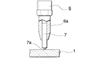
図2に示したように載置形溶植ヘッド(6)は、基板材料(1)に溶接されるピン形フィン(7)をつかむチャック(6a)を備えており、内部にチャック(6a)に連通したフィン通路が形成されており、チャック(6a)に上方からピン形フィン(7)が随時送られ、送られてきたピン形フィン(7)がチャック(6a)に掴まれて基板材料(1)上にスタッド溶接されるようになされている。
【0016】
基板材料(1)上に溶接されるピン形フィン(7)は、例えば、直径1mm、高さ5mmの断面円形状でかつ先端部にテーパ状部を介して突部(7a)を有し、溶接時に適度なアークが発生するようになされている。
【0017】
上記の装置を用い、アンコイラー(2)から巻き戻されている基板材料(1)上に、ピン形フィン(7)が、例えば、前後左右に3mmの間隔をおいてアークスタッド溶接され、ピン形フィン(7)が基板材料(1)に植え付けられる。ピン形フィン(7)がスタッド溶接された基板材料(1)は、リコイラーに巻き取られる。リコイラーに巻き取られた基板材料(1)は、後に適当な切断装置により所定の大きさに切断され、ピン形フィンを備えたヒートシンクが完成する。なお、基板材料(1)とピン形フィン(7)のスタッド溶接に要する時間は0.004秒程度ときわめて短く、基板材料(1)の巻き戻しに影響を与えることはない。
【0018】
上記の方法においては、アーク溶接によりピン形フィン(7)が基板材料(1)に溶接されているが、抵抗溶接および衝撃溶接により溶接してもよい。
【0019】
つぎに、図3および図4を参照して、本発明における第2実施形態の方法を説明する。図3は、本発明における第2実施形態の方法を実施するための装置の概略を示したものであり、この装置は、図1に示した装置におけるスタッドウェルダー(3)に代えてアンコイラー(2)からリコイラーヘの基板材料(1)の搬送経路中に上流側から順に設置された上下一対の加熱装置(13)と、打ち抜き機(14)と、フィンはめ込み装置(15)とを備えている。
【0020】
加熱装置(13)、打ち抜き機(14)およびはめ込み装置(15)の詳細な図示は省略したが、加熱装置(13)は、交流電源(16)と、基板材料(11)の上下に位置し、かつそれぞれ交流電源(16)に接続されたコイルが巻かれている2個の発熱体(17)とを備えたものであり、打ち抜き機(11)は、基板材料(11)に、幅方向に並んだ孔(10)を1列ごとに形成するものであり、ピン形フィンはめ込み装置(15)は、ピン形フィン(12)をつかむ複数のチャック(18)を備え、上下に移動して形成された孔(10)1列ごとにピン形フィン(12)をはめ込むものである。
【0021】
そして、アンコイラー(2)にコイル状に巻き取られた基板材料(11)を間欠的に巻き戻して加熱装置(13)に送り、加熱した後、打ち抜き機(14)により基板材料(11)に打ち抜き加工を施してピン形フィン(12)を焼きばめることができる径の多数の孔(10)を形成する。そして、基板材料(11)が加熱されることにより膨張し、各孔(10)が拡径した状態において、あらかじめ押し出し加工等により製造されたピン形フィン(12)の下端部をはめ込み装置(15)により各孔(10)に嵌め入れる。この後、基板材料(11)を適当な冷却装置(図示略)により冷却し、各孔(10)を縮径して基板材料(11)にピン形フィン(12)を固定する。このようにして基板材料(11)の各孔(10)にピン形フィン(12)を焼きばめるのである。
【0022】
ピン形フィン(12)が焼きばめられた基板材料(11)は、リコイラーに巻き取られる。リコイラーに巻き取られた基板材料(11)は、その後適当な切断装置により所定の大きさに切断され、図4に示したように、基板(19)および基板(19)上に立設された多数のピン形フィン(12)を備えているヒートシンクが完成する。
【0023】
なお、ピン形フィン(12)は、断面円形状の基部から断面略台形状の歯が8つ放射状に突出した断面星形状をなしており、対向する歯の頂面を結んだ直線の常温における長さは、孔(10)の常温における直径よりわずかに大きく、かつ基板材料(11)を加熱し、これが膨張した状態における拡径時の孔(10)の径よりわずかに小さくなされている。
【0024】
上記のように、断面星形状のピン形フィン(12)を用いると、ピン形フィン(12)の表面積を大きくすることができ、放熱性に優れたヒートシンクを製造できる。
【0025】
また、上記第2の実施形態においては基板材料(11)にピン形フィン(12)を焼きばめているが、これとは逆に、適当な冷却装置により冷却された冷風をピン形フィンに吹き付けてピン形フィンを冷却縮径し、縮径したピン形フィンを基板材料の孔に嵌め入れた後にピン形フィンを加熱してピン形フィンを膨張拡径させ、孔にピン形フィンを固定するようにしてもよい。基板材料の孔は、常温におけるピン形フィンの径より小さく、冷却して縮径した状態におけるピン形フィンの径より大きい径の孔である。
なお、ピン形フィン(7)(12)は、アルミニウム等の熱伝導率に優れた材料を用いて製造すればよい。
【0026】
【発明の効果】
本発明のピン形フィンを備えたヒートシンクの製造方法によれば、コイル状に巻き取られた基板材料を用意し、基板材料を巻き出すとともに巻き出された基板材料上にピン形フィンをスタッド溶接するので、切削や鍛造によりヒートシンクを製造する場合に比し、製造コストが安くなるとともに、複雑な形状のピン形フィンを備えたヒートシンクを容易に製造することができる
【0027】
また、コイル状に巻き取られた基板材料を用意し、基板材料を巻き出すとともに巻き出された基板材料に多数の孔を形成し、各孔にピン形フィンの一端部を焼きばめても上記と同様の効果を得ることができる。
【0028】
さらに、コイル状に巻き取られた基板材料を用意し、基板材料を巻き出すとともに巻き出された基板材料に多数の孔を形成し、各孔に冷却縮径したピン形フィンの一端部を嵌め入れた後ピン形フィンを加熱拡径して孔にピン形フィンを固定しても上記と同様の効果を得ることができる。
【図面の簡単な説明】
【図1】 本発明の第1の実施形態の方法を実施するための装置の概略斜視図である。
【図2】 図1の装置における要部の拡大断面図である。
【図3】 本発明の第2の方法を実施するための装置の概略斜視図である。
【図4】 図3のピン形フィンが嵌め入れられた基板材料の斜視図である。
【図5】 ピン形フィンを備えたヒートシンクの斜視図である。
【符号の説明】
(1)(11) 基板材料
(7)(12) ピン形フィン
(19) 基板[0001]
BACKGROUND OF THE INVENTION
The present invention relates to a method for manufacturing a heat sink having pin-shaped fins.
[0002]
[Prior art]
The heat sink including a substrate (21) and a large number of pin-shaped fins (22) erected on the substrate (21) shown in FIG. 5 has been conventionally manufactured by cutting or forging.
[0003]
[Problems to be solved by the invention]
In the case of the conventional heat sink manufacturing method, the yield is poor when cutting, and the production facilities are expensive when forging, and in any case, there is a problem that the heat sink is expensive.
[0004]
In the case of cutting and forging, there is also a problem that it is difficult to manufacture a heat sink having a pin-shaped fin having a complicated shape.
[0005]
An object of the present invention is to provide a method of manufacturing a heat sink, which can be manufactured easily with a complicated heat sink having pin-shaped fins, with a low manufacturing cost that solves the above problems.
[0006]
[Means for Solving the Problems]
The method of manufacturing a heat sink according to the first aspect of the present invention is a method of manufacturing a heat sink in which pin-shaped fins are erected in a plurality of rows on one side of a substrate, and the heat sink is wound in a number of pin-shaped fins and coils. Preparing the taken substrate material, unwinding the substrate material, stud welding the pin-shaped fins on one or more rows in the width direction on the substrate material that has been rewound and restored into a plate shape It is a feature.
[0007]
The invention of
[0008]
The method of manufacturing a heat sink according to the third aspect of the present invention is a method of manufacturing a heat sink in which pin-shaped fins are erected in a plurality of rows on one side of a substrate, wherein the heat sink is wound in a number of pin-shaped fins and coils. prepared taken substrate material, intermittently unwinding the substrate material, unwound with a pore diameter capable Mel shrink the pin-shaped fins restored substrate materials in a plate-like one or more And forming one end of each pin-shaped fin in each of the formed holes.
[0009]
According to a fourth aspect of the present invention, in the method of manufacturing a heat sink according to the third aspect, the pin-shaped fin has a star-shaped cross section in which teeth having a substantially trapezoidal cross section project radially from a base having a circular cross section. It is.
[0010]
A method of manufacturing a heat sink according to the present invention of
[0011]
DETAILED DESCRIPTION OF THE INVENTION
Hereinafter, with reference to drawings, the manufacturing method of the heat sink provided with the pin-shaped fin of the present invention is explained.
[0012]
FIG. 1 schematically shows an apparatus for carrying out the method according to the first embodiment of the present invention. This apparatus is connected to a suitable driving device (not shown) and has a prepared substrate material. The uncoiler (2) on which (1) is wound, and the recoiler (illustrated) that rotates in synchronization with the uncoiler (2) and winds up the substrate material (1) that has been unwound from the uncoiler (2) and restored to a plate shape. And an arc stud welder (3) installed in the transfer path of the substrate material (1) from the uncoiler (2) to the recoiler.
[0013]
The substrate material (1) wound around the uncoiler (2) is an aluminum wrought material, for example, formed into a plate shape having a thickness of 1.5 mm and a width of 30 mm.
[0014]
Although the detailed disclosure of the arc stud welder (3) is omitted, the arc stud welder (3) power supply AC welding (4), the transformer (5), comprising a plurality of mounting-standing溶植head (6) or the like It is a thing.
[0015]
As shown in FIG. 2, the mounting type fusion head (6) is provided with a chuck (6a) that holds a pin-shaped fin (7) welded to the substrate material (1). A communicating fin passage is formed, and the pin-shaped fin (7) is sent to the chuck (6a) from above as needed, and the fed pin-shaped fin (7) is gripped by the chuck (6a) to form the substrate material ( 1) Stud welded on top.
[0016]
The pin-shaped fin (7) welded onto the substrate material (1) has, for example, a circular cross section with a diameter of 1 mm and a height of 5 mm, and a protrusion (7a) through a tapered portion at the tip, A moderate arc is generated during welding.
[0017]
Using the above device, pin-shaped fins (7) are arc-stud welded, for example, 3 mm from front to back and left and right on the substrate material (1) unwound from the uncoiler (2), and then pin-shaped. Fins (7) are implanted in the substrate material (1). The substrate material (1) on which the pin-shaped fin (7) is stud-welded is wound up by a recoiler. The substrate material (1) taken up by the recoiler is later cut into a predetermined size by an appropriate cutting device to complete a heat sink having pin-shaped fins. The time required for stud welding of the substrate material (1) and the pin-shaped fin (7) is as short as about 0.004 seconds and does not affect the unwinding of the substrate material (1).
[0018]
In the above method, the pin-shaped fin (7) is welded to the substrate material (1) by arc welding, but may be welded by resistance welding and impact welding.
[0019]
Next, a method according to the second embodiment of the present invention will be described with reference to FIGS. FIG. 3 shows an outline of an apparatus for carrying out the method of the second embodiment of the present invention. This apparatus replaces the stud welder (3) in the apparatus shown in FIG. 1 with an uncoiler (2 ) To the recoiler, a pair of upper and lower heating devices (13), a punching device (14), and a fin fitting device (15) installed in order from the upstream side in the transport path of the substrate material (1) are provided.
[0020]
Although the detailed illustration of the heating device (13), punching machine (14) and fitting device (15) is omitted, the heating device (13) is located above and below the AC power source (16) and the substrate material (11). And two heating elements (17) each wound with a coil connected to an AC power source (16), and the punching machine (11) is arranged in the width direction on the substrate material (11). The pin-type fin insertion device (15) is provided with a plurality of chucks (18) that hold the pin-type fin (12) and moves up and down. The pin-shaped fins (12) are inserted into each row of the formed holes (10).
[0021]
Then, the substrate material (11) wound in a coil shape on the uncoiler (2) is intermittently rewound, sent to the heating device (13), heated, and then punched into the substrate material (11) by the punching machine (14). A number of holes (10) of a diameter that can be stamped to shrink the pin-shaped fins (12) are formed. Then, in the state where the substrate material (11) is heated to expand and the diameter of each hole (10) is expanded, the lower end portion of the pin-shaped fin (12) manufactured in advance by an extrusion process or the like is inserted (15 ) Fit into each hole (10). Thereafter, the substrate material (11) is cooled by a suitable cooling device (not shown), each hole (10) decreases in diameter to secure the pin-shaped fins (12) to the substrate material (11). In this way, pin-shaped fins (12) are shrink-fitted into each hole (10) of the substrate material (11).
[0022]
The substrate material (11) onto which the pin-shaped fins (12) have been shrink-fitted is taken up by a recoiler. The substrate material (11) wound up by the recoiler was then cut into a predetermined size by an appropriate cutting device, and was erected on the substrate (19) and the substrate (19) as shown in FIG. A heat sink with a number of pin-shaped fins (12) is completed.
[0023]
The pin-shaped fin (12) has a star-shaped cross section in which eight teeth having a substantially trapezoidal cross section project radially from a base having a circular cross section, and a straight line connecting the top surfaces of the opposing teeth at room temperature. The length is slightly larger than the diameter of the hole (10) at room temperature and slightly smaller than the diameter of the hole (10) when the substrate material (11) is heated and expanded.
[0024]
As described above, when the pin-shaped fin (12) having a star-shaped cross section is used, the surface area of the pin-shaped fin (12) can be increased, and a heat sink excellent in heat dissipation can be manufactured.
[0025]
In the second embodiment, the pin-shaped fin (12) is shrink-fitted on the substrate material (11). On the contrary, the cold air cooled by an appropriate cooling device is applied to the pin-shaped fin. The pin-shaped fin is cooled and reduced in diameter, and the pin-shaped fin is inserted into the hole in the substrate material, and then the pin-shaped fin is heated to expand and expand the pin-shaped fin, and the pin-shaped fin is fixed to the hole. You may make it do. The hole in the substrate material is a hole having a diameter smaller than the diameter of the pin-shaped fin at normal temperature and larger than the diameter of the pin-shaped fin in the cooled state.
The pin-shaped fins (7) and (12) may be manufactured using a material having excellent thermal conductivity such as aluminum.
[0026]
【The invention's effect】
According to the method of manufacturing a heat sink having pin-shaped fins of the present invention, a substrate material wound in a coil shape is prepared, and the substrate material is unwound and the pin-shaped fin is stud-welded on the unwound substrate material. Therefore, the manufacturing cost is lower than that in the case of manufacturing a heat sink by cutting or forging, and a heat sink having a pin-shaped fin having a complicated shape can be easily manufactured.
Also, it is possible to prepare a substrate material wound in a coil shape, unwind the substrate material, form a large number of holes in the unwound substrate material, and shrink one end of the pin-shaped fin into each hole The same effect as described above can be obtained.
[0028]
Furthermore, a substrate material wound in a coil shape is prepared, the substrate material is unwound, a large number of holes are formed in the unwound substrate material, and one end of a pin-shaped fin having a reduced diameter is fitted into each hole. The same effect as described above can be obtained even if the pin-shaped fin is heated and expanded after being inserted and the pin-shaped fin is fixed to the hole.
[Brief description of the drawings]
1 is a schematic perspective view of an apparatus for carrying out the method of the first embodiment of the present invention.
FIG. 2 is an enlarged cross-sectional view of a main part in the apparatus of FIG.
FIG. 3 is a schematic perspective view of an apparatus for carrying out the second method of the present invention.
4 is a perspective view of a substrate material pin-shaped fins are fitted in FIG.
FIG. 5 is a perspective view of a heat sink provided with pin-shaped fins.
[Explanation of symbols]
(1) (11) Board material (7) (12) Pin-shaped fin (19) Board
Claims (5)
Priority Applications (1)
| Application Number | Priority Date | Filing Date | Title |
|---|---|---|---|
| JP13059897A JP3692437B2 (en) | 1997-05-21 | 1997-05-21 | Heat sink manufacturing method |
Applications Claiming Priority (1)
| Application Number | Priority Date | Filing Date | Title |
|---|---|---|---|
| JP13059897A JP3692437B2 (en) | 1997-05-21 | 1997-05-21 | Heat sink manufacturing method |
Publications (2)
| Publication Number | Publication Date |
|---|---|
| JPH10321774A JPH10321774A (en) | 1998-12-04 |
| JP3692437B2 true JP3692437B2 (en) | 2005-09-07 |
Family
ID=15038048
Family Applications (1)
| Application Number | Title | Priority Date | Filing Date |
|---|---|---|---|
| JP13059897A Expired - Fee Related JP3692437B2 (en) | 1997-05-21 | 1997-05-21 | Heat sink manufacturing method |
Country Status (1)
| Country | Link |
|---|---|
| JP (1) | JP3692437B2 (en) |
Families Citing this family (10)
| Publication number | Priority date | Publication date | Assignee | Title |
|---|---|---|---|---|
| US6591897B1 (en) * | 2002-02-20 | 2003-07-15 | Delphi Technologies, Inc. | High performance pin fin heat sink for electronics cooling |
| JP5028147B2 (en) * | 2007-05-29 | 2012-09-19 | 株式会社アライドマテリアル | Heat spreader for semiconductor device and manufacturing method thereof |
| KR100877400B1 (en) | 2007-08-17 | 2009-01-07 | 최동철 | Apparatus for assembling heat sink |
| KR100888646B1 (en) | 2007-08-17 | 2009-03-17 | 최동철 | Apparatus for assembling heat sink |
| CN102183161A (en) * | 2011-01-25 | 2011-09-14 | 国研高能(北京)稳态传热传质技术研究院有限公司 | Vapor chamber |
| JP6064191B2 (en) * | 2012-08-30 | 2017-01-25 | 太陽工業株式会社 | Heat sink and heat sink manufacturing method |
| CN104124331A (en) * | 2014-07-04 | 2014-10-29 | 张逸兴 | Radiating device of LED |
| JP6775374B2 (en) | 2016-10-07 | 2020-10-28 | 昭和電工株式会社 | Manufacturing method of heat dissipation unit |
| JP7243262B2 (en) | 2019-02-15 | 2023-03-22 | 富士電機株式会社 | Semiconductor module, vehicle and manufacturing method |
| US20220279678A1 (en) * | 2019-09-06 | 2022-09-01 | Dai Nippon Printing Co., Ltd. | Vapor chamber, electronic device, sheet for vapor chamber, sheet where multiple intermediates for vapor chamber are imposed, roll of wound sheet where multiple intermediates for vapor chamber are imposed, and intermediate for vapor chamber |
-
1997
- 1997-05-21 JP JP13059897A patent/JP3692437B2/en not_active Expired - Fee Related
Also Published As
| Publication number | Publication date |
|---|---|
| JPH10321774A (en) | 1998-12-04 |
Similar Documents
| Publication | Publication Date | Title |
|---|---|---|
| JP3692437B2 (en) | Heat sink manufacturing method | |
| CA1059396A (en) | Method of sizing heat exchange panels | |
| JPS61198508A (en) | Sleeve for identifying wire and formation thereof | |
| MXPA04000495A (en) | Method of making a lanced and offset fin. | |
| US9073143B2 (en) | Automation of reaction metallurgical joining for copper conductors | |
| JPS63264218A (en) | Manufacture of heat exchanger tube and its apparatus | |
| US20200266559A1 (en) | Method for manufacturing solder with ground bar and coaxial cable array | |
| JP2002071286A (en) | Flat tube for heat exchanger and method for manufacturing the same | |
| ITMI980924A1 (en) | MACHINE WITH SERIES OF MOLDS AND METHOD OF MANUFACTURE OF FINS HEAT EXCHANGERS | |
| CA2563604C (en) | Stranded bar to solidified bar braze method and series loop connection | |
| US7256364B2 (en) | Method for simultaneous resistance brazing of adjacent conductor joints | |
| JPH0880013A (en) | Iron core comprising iron core plate with projected portion, its manufacture, punching die, apparatus for manufacturing the iron core plate, and device and method of manufacturing the iron core plate | |
| JPH02268966A (en) | Manufacture of heat exchanger | |
| JP3575671B2 (en) | End joining method for pair of conductors | |
| JP2894218B2 (en) | Method and apparatus for manufacturing flexible wiring | |
| US4361954A (en) | Method of and apparatus for the production of a toaster heating element | |
| JP2542553B2 (en) | Method for manufacturing synthetic resin decorative piece | |
| JPH0356808B2 (en) | ||
| JP2000323367A (en) | Electrode foil strip winding device | |
| KR19980071026A (en) | Sheet for manufacturing fins for heat exchanger and fins for heat exchanger | |
| JPH11260373A (en) | Manufacture of spreading mesh sheet and its manufacturing equipment | |
| JPH0710703B2 (en) | Flexible substrate assembly for solid parts and method of making same | |
| JPH0147256B2 (en) | ||
| JPH044076B2 (en) | ||
| JP2518648B2 (en) | Method of manufacturing brush assembly |
Legal Events
| Date | Code | Title | Description |
|---|---|---|---|
| A521 | Written amendment |
Free format text: JAPANESE INTERMEDIATE CODE: A523 Effective date: 20040518 |
|
| A621 | Written request for application examination |
Free format text: JAPANESE INTERMEDIATE CODE: A621 Effective date: 20040518 |
|
| A977 | Report on retrieval |
Free format text: JAPANESE INTERMEDIATE CODE: A971007 Effective date: 20050201 |
|
| A131 | Notification of reasons for refusal |
Free format text: JAPANESE INTERMEDIATE CODE: A131 Effective date: 20050208 |
|
| A521 | Written amendment |
Free format text: JAPANESE INTERMEDIATE CODE: A523 Effective date: 20050307 |
|
| A521 | Written amendment |
Free format text: JAPANESE INTERMEDIATE CODE: A523 Effective date: 20050408 |
|
| TRDD | Decision of grant or rejection written | ||
| A01 | Written decision to grant a patent or to grant a registration (utility model) |
Free format text: JAPANESE INTERMEDIATE CODE: A01 Effective date: 20050510 |
|
| A61 | First payment of annual fees (during grant procedure) |
Free format text: JAPANESE INTERMEDIATE CODE: A61 Effective date: 20050606 |
|
| R150 | Certificate of patent or registration of utility model |
Free format text: JAPANESE INTERMEDIATE CODE: R150 |
|
| LAPS | Cancellation because of no payment of annual fees |