EP3166115A1 - Isolationsstrukturen für elektrische systeme - Google Patents
Isolationsstrukturen für elektrische systeme Download PDFInfo
- Publication number
- EP3166115A1 EP3166115A1 EP16197819.2A EP16197819A EP3166115A1 EP 3166115 A1 EP3166115 A1 EP 3166115A1 EP 16197819 A EP16197819 A EP 16197819A EP 3166115 A1 EP3166115 A1 EP 3166115A1
- Authority
- EP
- European Patent Office
- Prior art keywords
- nanocomposite
- filler
- recited
- nanotubes
- nanophase
- Prior art date
- Legal status (The legal status is an assumption and is not a legal conclusion. Google has not performed a legal analysis and makes no representation as to the accuracy of the status listed.)
- Withdrawn
Links
- 238000002955 isolation Methods 0.000 title description 9
- 239000002114 nanocomposite Substances 0.000 claims abstract description 80
- 239000002071 nanotube Substances 0.000 claims abstract description 57
- 239000000463 material Substances 0.000 claims abstract description 53
- 239000000945 filler Substances 0.000 claims abstract description 47
- 239000011159 matrix material Substances 0.000 claims abstract description 38
- 239000004020 conductor Substances 0.000 claims abstract description 17
- 238000004891 communication Methods 0.000 claims abstract description 3
- 239000002131 composite material Substances 0.000 claims description 23
- 239000000203 mixture Substances 0.000 claims description 20
- 238000012546 transfer Methods 0.000 claims description 10
- 229910052582 BN Inorganic materials 0.000 claims description 6
- PZNSFCLAULLKQX-UHFFFAOYSA-N Boron nitride Chemical compound N#B PZNSFCLAULLKQX-UHFFFAOYSA-N 0.000 claims description 6
- 239000000615 nonconductor Substances 0.000 claims description 4
- 239000000853 adhesive Substances 0.000 claims description 3
- 230000001070 adhesive effect Effects 0.000 claims description 3
- 238000010438 heat treatment Methods 0.000 claims description 3
- 239000011347 resin Substances 0.000 claims description 3
- 229920005989 resin Polymers 0.000 claims description 3
- 238000004804 winding Methods 0.000 claims description 3
- 230000003014 reinforcing effect Effects 0.000 claims description 2
- 238000000034 method Methods 0.000 description 6
- 239000002019 doping agent Substances 0.000 description 4
- 239000012212 insulator Substances 0.000 description 4
- 230000000704 physical effect Effects 0.000 description 3
- -1 e.g. Substances 0.000 description 2
- 239000002245 particle Substances 0.000 description 2
- RYGMFSIKBFXOCR-UHFFFAOYSA-N Copper Chemical compound [Cu] RYGMFSIKBFXOCR-UHFFFAOYSA-N 0.000 description 1
- 230000002079 cooperative effect Effects 0.000 description 1
- 229910052802 copper Inorganic materials 0.000 description 1
- 239000010949 copper Substances 0.000 description 1
- 230000017525 heat dissipation Effects 0.000 description 1
- 238000010348 incorporation Methods 0.000 description 1
- 238000012986 modification Methods 0.000 description 1
- 230000004048 modification Effects 0.000 description 1
- 239000004033 plastic Substances 0.000 description 1
- 229920003023 plastic Polymers 0.000 description 1
Images



Classifications
-
- H—ELECTRICITY
- H01—ELECTRIC ELEMENTS
- H01B—CABLES; CONDUCTORS; INSULATORS; SELECTION OF MATERIALS FOR THEIR CONDUCTIVE, INSULATING OR DIELECTRIC PROPERTIES
- H01B3/00—Insulators or insulating bodies characterised by the insulating materials; Selection of materials for their insulating or dielectric properties
- H01B3/18—Insulators or insulating bodies characterised by the insulating materials; Selection of materials for their insulating or dielectric properties mainly consisting of organic substances
- H01B3/30—Insulators or insulating bodies characterised by the insulating materials; Selection of materials for their insulating or dielectric properties mainly consisting of organic substances plastics; resins; waxes
-
- C—CHEMISTRY; METALLURGY
- C08—ORGANIC MACROMOLECULAR COMPOUNDS; THEIR PREPARATION OR CHEMICAL WORKING-UP; COMPOSITIONS BASED THEREON
- C08K—Use of inorganic or non-macromolecular organic substances as compounding ingredients
- C08K3/00—Use of inorganic substances as compounding ingredients
- C08K3/38—Boron-containing compounds
-
- H—ELECTRICITY
- H01—ELECTRIC ELEMENTS
- H01B—CABLES; CONDUCTORS; INSULATORS; SELECTION OF MATERIALS FOR THEIR CONDUCTIVE, INSULATING OR DIELECTRIC PROPERTIES
- H01B3/00—Insulators or insulating bodies characterised by the insulating materials; Selection of materials for their insulating or dielectric properties
- H01B3/002—Inhomogeneous material in general
-
- H—ELECTRICITY
- H01—ELECTRIC ELEMENTS
- H01B—CABLES; CONDUCTORS; INSULATORS; SELECTION OF MATERIALS FOR THEIR CONDUCTIVE, INSULATING OR DIELECTRIC PROPERTIES
- H01B7/00—Insulated conductors or cables characterised by their form
- H01B7/02—Disposition of insulation
-
- H—ELECTRICITY
- H01—ELECTRIC ELEMENTS
- H01H—ELECTRIC SWITCHES; RELAYS; SELECTORS; EMERGENCY PROTECTIVE DEVICES
- H01H1/00—Contacts
- H01H1/02—Contacts characterised by the material thereof
- H01H1/021—Composite material
-
- C—CHEMISTRY; METALLURGY
- C08—ORGANIC MACROMOLECULAR COMPOUNDS; THEIR PREPARATION OR CHEMICAL WORKING-UP; COMPOSITIONS BASED THEREON
- C08K—Use of inorganic or non-macromolecular organic substances as compounding ingredients
- C08K3/00—Use of inorganic substances as compounding ingredients
- C08K3/38—Boron-containing compounds
- C08K2003/382—Boron-containing compounds and nitrogen
- C08K2003/385—Binary compounds of nitrogen with boron
Definitions
- the present disclosure relates to electrical systems, and more particularly to structures for electrically isolating energized and non-energized structures in electrical systems.
- Aircraft electrical systems commonly include isolation that electrically insulates energized structures from non-energized structures.
- the isolation generally includes materials with a dielectric constant and thermal conductivity suitable for dissipating heat generated by energized structures.
- the low dielectric constant of the material typically enables the isolation to electrically insulate the energized structure from surrounding de-energized structures.
- the thermal conductivity of the material is typically such that, when power is applied to an energized structure, heat generated by the energized structure readily dissipates to the surrounding environment.
- materials used for electrical isolation include plastics materials, which typically include a polymeric material doped with a material to enhance the thermal conductivity of the material without impairing the resistivity of the polymeric material.
- the dopants disposed within the polymeric material can influence certain physical properties of the material, typically according to the amount of dopant incorporated in the polymeric material. For example, increasing the amount of dopant to improve thermal conductivity can reduce the material strength of some materials and/or render the material more dense than materials with lower amounts of dopant.
- a nanocomposite structure includes a nanocomposite.
- the nanocomposite includes a bulk matrix phase and a nanophase filler distributed within the bulk matrix phase.
- the nanophase filler includes a plurality of nanotubes with a material having thermal conductivity that is greater than the thermal conductivity of the bulk matrix phase of the nanocomposite.
- the nanotubes can have lengths and widths where the length is greater than the width of the nanotube.
- the length can be substantially greater than the width of the nanotube, e.g., the width of a given nanotube being greater than ten (10) times the width of the nanotube.
- Widths of the nanotubes can be submicron; lengths of the nanotubes can be micron-size or greater.
- Two or more of the nanotubes can be in contact with one another within the bulk matrix phase.
- Two or more of the nanotubes can intermesh with one another within the bulk matrix phase.
- the intermeshed nanotubes can form a fibrous body within the nanocomposite, heat transfer and/or the material strength of the nanocomposite being anisotropic.
- the nanocomposite can have thermal conductivity that is greater than the thermal conductivity of a composite having an equivalent volume fraction of filler material with the same composition as the nanophase, in a particulate form, and disposed within the bulk matrix phase.
- the nanocomposite can have strength that is greater than the strength of a composite with an equivalent volume fraction of filler material of the same composition as the nanophase, in a particulate form, and disposed within the bulk matrix phase.
- the nanocomposite can have thermal conductivity that is equivalent to the thermal conductivity of a composite with a greater volume fraction of a filler material with the same composition as the nanophase, in a particulate form, and disposed within the bulk matrix phase.
- the nanocomposite can have a greater thermal conductivity and/or material strength than a composite with an equivalent volume fraction of filler material of the same composition as the nanophase, in a particulate form, and disposed within the bulk matrix phase.
- An electrical device includes a structure as described above and a conductor in thermal communication with the structure.
- the structure is configured and adapted to transfer heat generated by resistive heating of the conductor to the environment external to the electrical device.
- the conductor can includes a wire, a cable, a coil, or a winding.
- the structure can be a housing or a moveable element of a contactor or breaker assembly. It is also contemplated that the structure can be in intimate mechanical contact with the conductor, such as a sheath for a wire or a cable.
- Electrical device 10 includes a conductor 12 and a nanocomposite structure 14.
- Conductor 12 includes an electrical conductive material 16, like copper, and is in intimate mechanical contact with nanocomposite structure 14.
- Nanocomposite structure 14 includes a nanocomposite 100 that electrically isolates conductor 12 from the environment external to electrical device 10 and allows heat H, such as heat generated from resistive heating of conductor 12 from current flowing therethrough, to dissipate the environment external to electrical device 10 through nanocomposite structure 14.
- Nanocomposite 100 can be an electrical insulator.
- conductor 12 is in intimate mechanical contact with nanocomposite structure 14 to facilitate heat dissipation from conductor 12.
- Conductor 12 may be a wire, a cable, a coil, and a winding for an electrical component of an aircraft electrical system.
- Nanocomposite structure 14 may be a housing, a sheath for a wire or cable, or a movable element for a breaker or a contactor in an electrical component of an aircraft electrical system.
- Nanocomposite 100 includes a bulk matrix phase 102 and a nanophase filler 104.
- Bulk matrix phase 102 can be an insulator and includes one or more of a polymeric material, a resin material, and/or an adhesive material with predetermined physical properties including a thermal conductivity T 102 , a material strength S 102 , and an electrical resistivity R 102 .
- Nanophase filler 104 can be an electrical insulator. In embodiments, nanophase filler 104 has an electrical resistance that is greater than 10 12 ⁇ cm. In certain embodiments, nanophase filler 104 has an electrical resistance that is greater than 10 14 ⁇ cm.
- Nanophase filler 104 has predetermined physical properties including a thermal conductivity T 104 , a material strength S 104 , and an electrical resistivity R 104 .
- resistivity R 104 of nanophase filler 104 can be equal to or greater than the resistivity R 102 of bulk matrix phase 102.
- thermal conductivity T 104 of nanophase filler 104 is greater than the thermal conductivity T 102 of bulk matrix phase 102.
- material strength of S 104 of nanophase filler 104 is greater than material strength S 102 of bulk matrix phase 102. In this respect one or more of the yield strength, compressive strength, tensile strength, fatigue strength, and/or impact strength of nanophase filler 104 may be greater than that of bulk matrix phase 102.
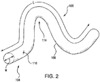
- Nanotube 106 has a tubular body 108 with a serpentine shape 112 and including one or more arcuate segments 114.
- Tubular body 108 defines a width W and a length L extending between opposite ends of tubular body 108.
- Length L is greater than width W.
- length L is greater than a micron and width W is smaller than one micron in size.
- length L of nanotube 106 is substantially greater than width W, e.g., length L being more than ten (10) times the size of width W.
- nanotube 106 includes a boron nitride composition 116.
- incorporation of boron nitride in nanocomposite structures can increase the thermal conductivity of the structure without reducing the resistivity and electrical isolation provided by the nanocomposite structure.
- Nanophase filler 104 includes a plurality of nanotubes 106A-106C that are in contact with one another at contact locations 116. Contact between nanotubes 106A-106C at contact locations 116 enables heat H (shown in Fig. 1 ) to transfer through nanotubes 106A-106C serially, and without the need for the heat to cross an intervening gap defined between nanotubes 106A-106C by bulk matrix phase 102.
- heat H shown in Fig. 1
- serial heat transfer between contacting nanotubes improves heat transfer through a nanocomposite when heat transfers more rapidly through the nanotubes than the surrounding bulk matrix phase.
- Nanophase filler 104 also includes a plurality of nanotubes 106D-106F that intermesh with one another. Intermeshing of nanotubes 106D-106F cause force applied to one of intermeshed nanotubes 106D-106F to transfer through the intermeshed nanotubes to the other intermeshed nanotubes.
- a force F applied to nanotube 106D exerts associated force components on nanotube 106E and nanotube 106F, distributing force exerted on one of the nanotubes across the other intermeshed nanotubes.
- the distribution of the force reduces the peak stress exerted locally on nanocomposite 100, enabling nanocomposite 100 to withstand greater force than would otherwise be possible.
- intermeshed nanotubes 106D-106F provide heat transfer benefits similar to those of contacting nanotubes 106A-106C.
- Intermeshed nanotubes 106D-106F form a fibrous body 118 disposed within bulk matrix phase 102. Fibrous body 118 supports bulk matrix phase 102, reinforcing bulk matrix phase 102.
- the contacting nanotubes, e.g., nanotubes 106A-106C, and the intermeshed nanotubes, e.g., nanotubes 106D-106F are well distributed within nanocomposite structure.
- Fig. 4 shows a composite 200 with boron nitride particles 202 incorporated in bulk matrix phase 102.
- nanocomposite 100 shows superior material strength relative to composite 200.
- nanocomposite 100 provides superior material strength relative to composite 200.
- increasing volume fractions of nanophase filler 104 shown in Fig. 1
- increasing volume fractions of the filler composition in particle form tend to decrease the material strength of composite 200.
- nanocomposite 100 provides superior thermal conductivity in comparison to composite 200.
- increasing volume fractions of nanophase 104 realize greater thermal conductivities than equivalent volume fractions of the composition in particulate form. This enables nanocomposite structures formed from nanocomposite 100 to provide the same thermal conductivity as composite structures formed from composite 200 with a lower volume fraction of filler. In embodiments where the filler composition is more dense than the bulk matrix phase, this reduces the density (and weight) of the resulting structure.
- nanocomposites include nanophase fillers with compositions having a greater thermal conductivity than the compositions incorporated in the bulk matrix phase of the nanocomposite.
- the compositions are electrically resistive, and have electrical resistance that is equivalent or greater than the electrical resistance of the composition(s) forming the bulk matrix phase material. This allows structures formed from the nanocomposites to provide electrical isolation with improved thermal conductivity.
- the nanophase filler includes the composition in nanotube form.
- the discrete nanotubes contact and/or intermesh with one another within the bulk matrix phase, thereby forming a fibrous body within the bulk matrix body.
- the contacting and/or intermeshed nanotubes within the bulk nanophase are randomly oriented and well distributed within the bulk nanophase, thereby providing anisotropic thermal conductivity and/or material strength. It is contemplated that the contacting and/or intermeshed nanotubes of the fibrous body provide equivalent or superior thermal conductivity and/or material strength than a composite including the composition of the nanophase in particulate form, thereby providing weight savings through lower relative density.
Landscapes
- Chemical & Material Sciences (AREA)
- Physics & Mathematics (AREA)
- Spectroscopy & Molecular Physics (AREA)
- Engineering & Computer Science (AREA)
- Composite Materials (AREA)
- Materials Engineering (AREA)
- Health & Medical Sciences (AREA)
- Chemical Kinetics & Catalysis (AREA)
- Medicinal Chemistry (AREA)
- Polymers & Plastics (AREA)
- Organic Chemistry (AREA)
- Compositions Of Macromolecular Compounds (AREA)
Applications Claiming Priority (1)
| Application Number | Priority Date | Filing Date | Title |
|---|---|---|---|
| US14/936,605 US20170133120A1 (en) | 2015-11-09 | 2015-11-09 | Isolation structures for electrical systems |
Publications (1)
| Publication Number | Publication Date |
|---|---|
| EP3166115A1 true EP3166115A1 (de) | 2017-05-10 |
Family
ID=57281064
Family Applications (1)
| Application Number | Title | Priority Date | Filing Date |
|---|---|---|---|
| EP16197819.2A Withdrawn EP3166115A1 (de) | 2015-11-09 | 2016-11-08 | Isolationsstrukturen für elektrische systeme |
Country Status (2)
| Country | Link |
|---|---|
| US (1) | US20170133120A1 (de) |
| EP (1) | EP3166115A1 (de) |
Families Citing this family (1)
| Publication number | Priority date | Publication date | Assignee | Title |
|---|---|---|---|---|
| KR102898149B1 (ko) * | 2020-08-20 | 2025-12-09 | 덴카 주식회사 | 질화 붕소 입자, 수지 조성물, 및 수지 조성물의 제조 방법 |
Citations (2)
| Publication number | Priority date | Publication date | Assignee | Title |
|---|---|---|---|---|
| US20050116336A1 (en) * | 2003-09-16 | 2005-06-02 | Koila, Inc. | Nano-composite materials for thermal management applications |
| US20090032259A1 (en) * | 2007-05-08 | 2009-02-05 | Baker Hughes Incorporated | Downhole applications of composites having aligned nanotubes for heat transport |
-
2015
- 2015-11-09 US US14/936,605 patent/US20170133120A1/en not_active Abandoned
-
2016
- 2016-11-08 EP EP16197819.2A patent/EP3166115A1/de not_active Withdrawn
Patent Citations (2)
| Publication number | Priority date | Publication date | Assignee | Title |
|---|---|---|---|---|
| US20050116336A1 (en) * | 2003-09-16 | 2005-06-02 | Koila, Inc. | Nano-composite materials for thermal management applications |
| US20090032259A1 (en) * | 2007-05-08 | 2009-02-05 | Baker Hughes Incorporated | Downhole applications of composites having aligned nanotubes for heat transport |
Non-Patent Citations (1)
| Title |
|---|
| CHUNYI ZHI ET AL: "Towards Thermoconductive, Electrically Insulating Polymeric Composites with Boron Nitride Nanotubes as Fillers", ADVANCED MATERIALS FOR OPTICS AND ELECTRONICS., vol. 19, no. 12, 20 April 2009 (2009-04-20), GB, pages 1857 - 1862, XP055357925, ISSN: 1057-9257, DOI: 10.1002/adfm.200801435 * |
Also Published As
| Publication number | Publication date |
|---|---|
| US20170133120A1 (en) | 2017-05-11 |
Similar Documents
| Publication | Publication Date | Title |
|---|---|---|
| RU2681643C1 (ru) | Кабельная арматура для соединения высоковольтного кабеля с высоковольтным компонентом | |
| CN101222156A (zh) | 用作电绝缘件的非线性电介质 | |
| JP2014518500A5 (de) | ||
| CN102369641B (zh) | 高压电气设备的导体 | |
| WO2019239862A1 (ja) | 導電路 | |
| CN1129995C (zh) | 用于大型电机的导体绕组装置 | |
| CN115331869B (zh) | 带有绝缘体的双母线 | |
| US20130157042A1 (en) | Electrically insulating material, insulating paper, and insulating tape for a high voltage rotary machine | |
| CN110235208B (zh) | 中压和高压线缆应用的多层应力控制制品及干式接线端 | |
| US20170133120A1 (en) | Isolation structures for electrical systems | |
| JP2006109600A (ja) | 回転電機の固定子コイルおよびその固定方法 | |
| CN109416145A (zh) | 用于高电压集肤效应追踪加热的屏蔽的导线 | |
| US10910179B2 (en) | Vacuum circuit breaker with improved configuration | |
| CN103403818A (zh) | 用于高压直流输电变压器线圈或扼流线圈的布线装置 | |
| US20100207600A1 (en) | Variable-Electric-Power Self-Regulating Cable Exhibiting PTC Behaviour, Connector Therefor, a Device Comprising Them, and Use of Said Device | |
| WO2019075685A1 (en) | SURFACE MOUNT FUSE DEVICE COMPRISING A POSITIVE TEMPERATURE COEFFICIENT BODY | |
| EP3402039A1 (de) | Isolation einer elektrischen maschine | |
| GB2545446A (en) | Power distribution connector | |
| CN104937673B (zh) | 用于高压设备的绝缘装置 | |
| CN110268485B (zh) | 用于恶劣环境的高功率套管 | |
| CN102447331A (zh) | 绝缘体系定子线棒高导热绝缘结构 | |
| JP2015088513A (ja) | インダクタ | |
| US11081923B2 (en) | Corona shielding system for an electrical machine | |
| EP3816218A1 (de) | Polymerkeramik-verbundwerkstoff und herstellungsverfahren dafür | |
| US873216A (en) | Electric cable. |
Legal Events
| Date | Code | Title | Description |
|---|---|---|---|
| PUAI | Public reference made under article 153(3) epc to a published international application that has entered the european phase |
Free format text: ORIGINAL CODE: 0009012 |
|
| STAA | Information on the status of an ep patent application or granted ep patent |
Free format text: STATUS: THE APPLICATION HAS BEEN PUBLISHED |
|
| AK | Designated contracting states |
Kind code of ref document: A1 Designated state(s): AL AT BE BG CH CY CZ DE DK EE ES FI FR GB GR HR HU IE IS IT LI LT LU LV MC MK MT NL NO PL PT RO RS SE SI SK SM TR |
|
| AX | Request for extension of the european patent |
Extension state: BA ME |
|
| STAA | Information on the status of an ep patent application or granted ep patent |
Free format text: STATUS: REQUEST FOR EXAMINATION WAS MADE |
|
| 17P | Request for examination filed |
Effective date: 20171110 |
|
| RBV | Designated contracting states (corrected) |
Designated state(s): AL AT BE BG CH CY CZ DE DK EE ES FI FR GB GR HR HU IE IS IT LI LT LU LV MC MK MT NL NO PL PT RO RS SE SI SK SM TR |
|
| STAA | Information on the status of an ep patent application or granted ep patent |
Free format text: STATUS: EXAMINATION IS IN PROGRESS |
|
| 17Q | First examination report despatched |
Effective date: 20181121 |
|
| STAA | Information on the status of an ep patent application or granted ep patent |
Free format text: STATUS: THE APPLICATION IS DEEMED TO BE WITHDRAWN |
|
| 18D | Application deemed to be withdrawn |
Effective date: 20190604 |