EP3165942A1 - Laser device - Google Patents
Laser device Download PDFInfo
- Publication number
- EP3165942A1 EP3165942A1 EP16197318.5A EP16197318A EP3165942A1 EP 3165942 A1 EP3165942 A1 EP 3165942A1 EP 16197318 A EP16197318 A EP 16197318A EP 3165942 A1 EP3165942 A1 EP 3165942A1
- Authority
- EP
- European Patent Office
- Prior art keywords
- light
- laser device
- reflection part
- reflector
- optical axis
- Prior art date
- Legal status (The legal status is an assumption and is not a legal conclusion. Google has not performed a legal analysis and makes no representation as to the accuracy of the status listed.)
- Granted
Links
Images





Classifications
-
- G—PHYSICS
- G01—MEASURING; TESTING
- G01S—RADIO DIRECTION-FINDING; RADIO NAVIGATION; DETERMINING DISTANCE OR VELOCITY BY USE OF RADIO WAVES; LOCATING OR PRESENCE-DETECTING BY USE OF THE REFLECTION OR RERADIATION OF RADIO WAVES; ANALOGOUS ARRANGEMENTS USING OTHER WAVES
- G01S7/00—Details of systems according to groups G01S13/00, G01S15/00, G01S17/00
- G01S7/48—Details of systems according to groups G01S13/00, G01S15/00, G01S17/00 of systems according to group G01S17/00
- G01S7/481—Constructional features, e.g. arrangements of optical elements
- G01S7/4811—Constructional features, e.g. arrangements of optical elements common to transmitter and receiver
- G01S7/4812—Constructional features, e.g. arrangements of optical elements common to transmitter and receiver transmitted and received beams following a coaxial path
-
- G—PHYSICS
- G01—MEASURING; TESTING
- G01S—RADIO DIRECTION-FINDING; RADIO NAVIGATION; DETERMINING DISTANCE OR VELOCITY BY USE OF RADIO WAVES; LOCATING OR PRESENCE-DETECTING BY USE OF THE REFLECTION OR RERADIATION OF RADIO WAVES; ANALOGOUS ARRANGEMENTS USING OTHER WAVES
- G01S17/00—Systems using the reflection or reradiation of electromagnetic waves other than radio waves, e.g. lidar systems
- G01S17/02—Systems using the reflection of electromagnetic waves other than radio waves
- G01S17/06—Systems determining position data of a target
- G01S17/08—Systems determining position data of a target for measuring distance only
-
- G—PHYSICS
- G01—MEASURING; TESTING
- G01S—RADIO DIRECTION-FINDING; RADIO NAVIGATION; DETERMINING DISTANCE OR VELOCITY BY USE OF RADIO WAVES; LOCATING OR PRESENCE-DETECTING BY USE OF THE REFLECTION OR RERADIATION OF RADIO WAVES; ANALOGOUS ARRANGEMENTS USING OTHER WAVES
- G01S7/00—Details of systems according to groups G01S13/00, G01S15/00, G01S17/00
- G01S7/48—Details of systems according to groups G01S13/00, G01S15/00, G01S17/00 of systems according to group G01S17/00
- G01S7/481—Constructional features, e.g. arrangements of optical elements
-
- G—PHYSICS
- G01—MEASURING; TESTING
- G01S—RADIO DIRECTION-FINDING; RADIO NAVIGATION; DETERMINING DISTANCE OR VELOCITY BY USE OF RADIO WAVES; LOCATING OR PRESENCE-DETECTING BY USE OF THE REFLECTION OR RERADIATION OF RADIO WAVES; ANALOGOUS ARRANGEMENTS USING OTHER WAVES
- G01S7/00—Details of systems according to groups G01S13/00, G01S15/00, G01S17/00
- G01S7/48—Details of systems according to groups G01S13/00, G01S15/00, G01S17/00 of systems according to group G01S17/00
- G01S7/481—Constructional features, e.g. arrangements of optical elements
- G01S7/4811—Constructional features, e.g. arrangements of optical elements common to transmitter and receiver
- G01S7/4813—Housing arrangements
-
- G—PHYSICS
- G01—MEASURING; TESTING
- G01S—RADIO DIRECTION-FINDING; RADIO NAVIGATION; DETERMINING DISTANCE OR VELOCITY BY USE OF RADIO WAVES; LOCATING OR PRESENCE-DETECTING BY USE OF THE REFLECTION OR RERADIATION OF RADIO WAVES; ANALOGOUS ARRANGEMENTS USING OTHER WAVES
- G01S7/00—Details of systems according to groups G01S13/00, G01S15/00, G01S17/00
- G01S7/48—Details of systems according to groups G01S13/00, G01S15/00, G01S17/00 of systems according to group G01S17/00
- G01S7/481—Constructional features, e.g. arrangements of optical elements
- G01S7/4817—Constructional features, e.g. arrangements of optical elements relating to scanning
Definitions
- the present invention generally relates to a laser device (measuring apparatus) for measuring distance to a target object by using light.
- Conventional measuring apparatuses measure distance to a target object by using a moveable mirror to deflect and emit a measuring light in a plurality of directions, thereby receiving the returning light of the measuring light as reflected by the target object via the moveable mirror.
- a measuring apparatus for what is called a coaxial optical system whereby the measuring light and the returning light enters and exits along the same optical axis by using an optical element such as a prism or mirror and the like, aligning the central axis of a light transmitter and the central axis of a light receiver (for example, refer to patent documents 1, 2).
- Laser devices that employ a coaxial optical system do not have measurement errors due to a parallax of the light transmitter and the light receiver because the optical axis of the measuring light and the optical axis of the returning light are aligned, however there is a disadvantage in that it is difficult to remove stray light interference wherein stray light generated by the measuring light being diffusely reflected in the housing wraps around the light receiver. This stray light interference is a possible cause for measurement errors.
- One or more embodiments of the present invention provide a laser device for reducing the parallax of the light transmitter and the light receiver, and for decreasing stray light interference.
- a laser device may comprise: a light transmitter for emitting light, a first reflector for reflecting the light, supported and oscillated by an oscillating shaft, a light receiver provided apart from the light transmitter in the direction of the oscillating shaft, an guide part for receiving the light from the first reflector and emitting from a position closer to the light receiver in the direction of the oscillating shaft, and a second reflector for reflecting the returning light from the target object of the light emitted from the guide part to the light receiver, and oscillating in sync with the first reflector.
- the light after being reflected by the first reflector may be shifted and emitted to a position close to the light receiver.
- light may be blocked between the first reflector and the second reflector, and the light and returning light may be separated, thereby decreasing the degree of wraparound of the stray light generated by the first reflector around the light receiver.
- the parallax of the light transmitter and the light receiver may be also reduced, as the emitting position of the light is brought closer to the light receiver.
- the first reflector and the second reflector are disposed on a same plane, and may be supported by the same oscillating shaft and oscillated.
- the first reflector and the second reflector that oscillate in sync may be implemented in a relatively simple configuration.
- the laser device further includes a housing, having a window for the light and the returning light to pass through, and the guide part may be provided on the window.
- the guide part has a first reflection part and a second reflection part that are facing, and the first reflection part may be disposed in a position where the window and the light intersect, and the second reflection part may be disposed in a position where the first reflection part is in parallel displacement close to the light receiver.
- the guide part may be specifically configured to emit the light input to the first reflection part from the second reflection part.
- the second reflection part may be provided in the same position as the central axis of the light receiver in the direction of the oscillating shaft.
- the parallax of the light transmitter and the light receiver may be minimized, as the position of the emitting position of the light and central axis of the light receiver conform in the direction of the oscillating shaft.
- the second reflection part may be provided in a different position to the central axis of the light receiver in the direction of the oscillating shaft.
- the second reflection part becomes an obstacle, and the input amount of the light receiver of the returning light is decreased may be reduced, as the second reflection part is disposed in a position offset from the central axis of the light receiver.
- the second reflection part may be moveably installed in the direction of the oscillating shaft.
- the distance to a target object positioned in a plurality of different distance measurement surfaces in the direction of the oscillating shaft may be measured by moving the second reflection part.
- the laser device further includes a shielding plate within the housing, and the second reflection part may be positioned closer to the light receiver than the shielding plate in the direction of the oscillating shaft.
- a transparent member may be provided on a planar shape parallel to the oscillating shaft.
- manufacture may configure the transparent member on a relatively simple flat board.
- the transparent member may be provided in a cylindrical shape as the center of the oscillating shaft.
- deviation may be minimized in the plane where the resultant light, returning light, and oscillating shaft bisect due to the guide part.
- a laser device may comprise a transmitter that emits a light, a first reflector that pivotally reflects the light by a shaft, a light receiver provided apart from the transmitter in a first direction parallel to the shaft, a guide part that receives the light from the first reflector and changes a direction of the light in the first direction, and a second reflector that reflects a returning light from an object and pivots in sync with the first reflector.
- the laser device may reduce the parallax of the light transmitter and the light receiver, and decrease stray light interference.
- parallel and perpendicular should be interpreted as approximately parallel and approximately perpendicular respectively. These terms denote being parallel and perpendicular with regard to design, and realistic measuring errors that occur due to member shape or assembly in the present laser device may be included.
- the laser device is a laser device for measuring a distance to a target object, by moving a measurement light that is emitted from a light transmitter by a light transmitting mirror (first reflector), scanning the range area, and receiving a returning light of the measuring light from the target object by a light receiver via a light receiving mirror (second reflector).
- the laser device may be called a measuring apparatus.
- the laser device separates the optical path of the measuring light and the optical path of the returning light that is reflected by the oscillating mirror, decreasing stray light interference, while an optical axis shift part (guide part) is provided for shifting the optical axis of the measuring light close to the light receiver in the latter stage of the oscillating mirror.
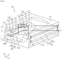
- FIG. 1 is a cutout perspective view drawing illustrating one example of a configuration of the laser device 101.
- the laser device 101 is provided with a housing 111, a light transmitter 120, a deflection part 140, an optical axis shift part 151, a light receiver 160, and a control part 190.
- the housing 111 is a box configuring the exterior of the laser device 101, and it houses the light transmitter 120, the deflection part 140, the light receiver 160, and the control part 190.
- the housing 111 may, for example, be configured by resin or metal.
- a light transmitting region 113 and a light receiving region 114 is partitioned by a shielding plate 112 in the internal space of the housing 111.
- the light transmitting region 113 is a region where primarily a measuring light 125 passes through, and the light receiving region 114 is a region where primarily a returning light 165 passes through.
- the internal space and the external space of the housing 111 (in short, the range area) is divided, while a housing window 115 is provided, configured of a transparent member where the measuring light 125 and the returning light 165 pass through.
- the housing window 115 may, for example, be a flat board made of resin or glass.
- the light transmitter 120 is an optical system for emitting the measuring light 125, and has a light source 121.
- the light source 121 may, for example, be configured of a laser diode.
- the light transmitter 120 may have a collimating lens 122 for collimating the measuring light 125, and may have a slit (not illustrated) for regulating the emitting direction of the measuring light 125.
- the optical axis of the measuring light 125 that faces a light transmitting mirror (first reflector) 141 emitted from the light transmitter 120 is defined as the central axis of the light transmitter 120.
- the direction of the central axis of the light transmitter 120 will be referred to as the y-axis.
- the deflection part 140 scans the range area using the measuring light 125 that is emitted from the light transmitter 120, and is an optical system including a moveable mirror for guiding the returning light 165 from the target object in the range area to the light receiver 160.
- the deflection part 140 is supported by an oscillating shaft 146, and has the light transmitting mirror 141 and a light receiving mirror (second reflector) 142 for oscillating due to torque applied by an actuator 143.
- the light transmitting mirror 141 and the light receiving mirror 142 may, for example, be configured of a metal film mirror, and may also be disposed on the same plane.
- the oscillating shaft 146 may, for example, be formed by punching through the thin metal film.
- a direction parallel to the oscillating shaft 146 shall be referred to as the z-axis, and the position of the z-axis direction will be referred to as the height.
- each of the light transmitting mirror 141 and the light receiving mirror 142 may, for example, be fixed to the oscillating shaft 146 by an adhesive or the like, and further, may be fixed to the housing 111 via a fixing part (not illustrated) provided on the upper and lower ends of the oscillating shaft 146.
- the actuator 143 may be an actuator using electromagnetic force, electrostatic force, or piezoelectric displacement as the torque source. For example, due to the actuator 143 generating cyclic torque, resonance occurs in the oscillating shaft 146 as a torsion bar, and the light transmitting mirror 141 and the light receiving mirror 142 oscillate around the z-axis.
- the light transmitting mirror 141 scans the range area with the measuring light 125 from the light transmitter 120 by oscillating.
- the optical axis shift part 151 receives the measuring light 125 after being reflected in the light transmitting mirror 141, and is an optical system for emitting the received measuring light 125 from a close height by the light receiver 160.
- the optical axis shift part 151 may, for example, be configured of a first reflection part 1511 and a second reflection part 1512 that are facing, and may be provided on the housing window 115. Detailed configuration of the optical axis shift part 151 will be described later.
- the measuring light 125 emitted from the optical axis shift part 151 arrives at the target object (not illustrated) within the range area, and is diffusely reflected by the target object.
- the returning light 165 that returns towards the laser device 101 passes through the housing window 115 of the laser device 101, and is input to the inside of the housing 111.
- the light receiving mirror 142 reflects the returning light 165 to the light receiver 160.
- the light receiver 160 is an optical system for exchanging the returning light 165 reflected in the light receiving mirror 142 to a received signal, and has a light receiving element 162.
- the light receiving element 162 may, for example, be configured of an avalanche photodiode.
- the light receiver 160 may have a condenser lens 161 for condensing the returning light 165 to the light receiving element 162, and may have a band-pass filter (not illustrated) for removing wavelength noise light other than the measuring light 125.
- the light receiver 160 is provided apart from the light transmitter 120 in a height wise direction.
- the optical axis of light input to the light receiver from the light receiving mirror 142 and condensed in the light receiving element 162 is defined as the central axis of the light receiver 160.
- the central axis of the light receiver 160 may, for example, be the central axis of the condenser lens 161, and may be parallel to the central axis of the light transmitter 120.
- the control part 190 is a controller for controlling distance measurement operation in the laser device 101.
- the control part 190 drives the light source 121 and the actuator 143, and calculates the distance to the target object from the laser device 101 by processing the received signal from the light receiving element 162.
- the control part 190 may be implemented by a combination of software function, carried out by a drive circuit for supplying a drive signal to the light source 121 and the actuator 143, a hardware function such as a signal processing circuit for receiving and processing a signal from the light receiving element 162, and a microcomputer executing a predetermined program.
- the control part 190 specifically, based on phase contrast between the received signal from the light receiving element 162 and the drive signal supplied to the light source 121, round trip time from the laser device 101 of the measuring light 125 to the target object is requested, and the distance to the target object may be calculated. Furthermore, the control part 190 may specify the direction of the target object within the range area from the angle of rotation (hereinafter referred to as the inclination) of around the oscillating shaft 146 of the light transmitting mirror 141.
- FIG. 2 is a perspective view drawing illustrating an example of a detailed configuration of the optical axis shift part 151.
- the first reflection part 1511 of the optical axis shift part 151 is disposed in a position where the housing window 115 and the measuring light 125 intersect.
- the first reflection part 1511 is provided on the height of the central axis of the light transmitter 120, on the outer surface of the housing window 115, and it may have a long mirror, having a reflective surface, forming an outer surface for the housing window 115 at a 45-degree angle.
- the second reflection part 1512 is disposed in a position displaced parallel to the first reflection part 1511, close to the light receiver 160. Specifically, the second reflection part 1512 is provided parallel to the first reflection part 1511 of the outer surface of the housing window 115, and on a lower position than the first reflection part 1511, and it may have a long mirror, having a reflective surface, forming an outer surface for the housing window 115 at a 135-degree angle.
- the first reflection part 1511 and the second reflection part 1512 may, for example, be held at each end by a holding member (not illustrated) provided on the housing 111, and may be fixed in the aforementioned position of the housing window 115.
- the optical axis of the measuring light 125 after being reflected by the light transmitting mirror 141 is bent in a direction parallel to the outer surface of the housing window 115 by the first reflection part 1511, and is once again bent and emitted in a direction parallel to the optical axis of the original measuring light 125 by the second reflection part 1512.
- the optical axis of the measuring light 125 is shifted to a height close to the light receiver 160 (specifically, the central axis of the light receiver 160) by the optical axis shift part 151, as illustrated in FIG. 1 .
- the optical axis shift part can be configured of a prism in place of a mirror. In the following, a modified example of such an optical axis shift part will be described.
- FIG. 3 is a perspective view drawing illustrating an example of a detailed configuration of the optical axis shift part 152 according to the modified example.
- the optical axis shift part 152 is configured of one prism, and a first reflection part 1521 and a second reflection part 1522 are a pair of reflective surfaces provided on the prism.
- the first reflection part 1521 is disposed in a position where the housing window 115 and the measuring light 125 intersect. Specifically, the reflective surface as the first reflection part 1521 may form the outer surface of the housing window 115 at a 45-degree angle.
- the second reflection part 1522 is disposed in a position displaced parallel to the first reflection part 1521, close to the light receiver 160.
- the reflective surface as the second reflection part 1522 may form the outer surface of the housing window 115 at a 135-degree angle.
- the optical axis shift part 152 may, for example, be adhered to the housing window 115, or be held at each end by a holding member (not illustrated) provided on the housing 111, and may be fixed in the aforementioned position.
- the optical axis of the measuring light 125 after being reflected by the light transmitting mirror 141 is bent in a direction parallel to the outer surface of the housing window 115 by the first reflection part 1521, and is once again bent and emitted in a direction parallel to the optical axis of the original measuring light 125.
- the optical axis of the measuring light 125 is shifted to a height close to the light receiver 160 (specifically, the central axis of the light receiver 160) by the optical axis shift part 152, as illustrated in FIG. 3 .
- Results obtained by the laser device 101 configured as per the abovementioned will be described based on a comparison of a plurality of comparative examples.
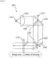
- FIG. 4 is a top view drawing illustrating an example of the optical path of the measuring light and the returning light of a laser device 801 according to comparative example 1.
- the laser device 801 is an example of a coaxial optical system laser device stated in the related art.
- the measuring light 125 emitted from the light source 121 and the returning light 165 condensed in the light receiving element 162 by the condenser lens 161 are overlaid on the same optical axis by a perforated mirror 158, and is moved in a plurality of directions by a moveable mirror 148, and then emitted to the range area from the housing window 115.
- a stray light 129 generated by the inner surface of the perforated mirror 158, the moveable mirror 148 and the housing window 115 cannot be separated from the returning light 165.
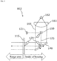
- FIG. 5 is a top view drawing illustrating an example of the optical path of the measuring light and the returning light of a laser device 802 according to comparative example 2.
- the laser device 802 is an example of a coaxial optical system laser device stated in the related art.
- the measuring light 125 emitted from the light source 121 and the returning light 165 condensed in the light receiving element 162 by the condenser lens 161 are overlaid on the same optical axis by a mirror 159, is moved in a plurality of directions by the moveable mirror 148, and then emitted to the range area from the housing window 115.
- the stray light 129 generated by the inner surface of the mirror 159, the moveable mirror 148 and the housing window 115 cannot be separated from the returning light 165.
- the inventor has examined a separating optical system laser device for processing the measuring light and the returning light through a separated space within the housing of both, without being disposed on the same optical axis within the housing.
- FIG. 6 is a side view drawing illustrating an example of the optical path of the measuring light and returning light of a laser device 803 according to comparative example 3.
- the light transmitting region 113 and a light receiving region 114 is partitioned by a shielding plate 112 in the inside of the housing.
- the light transmitting mirror 141 and the light receiving mirror 142 are provided apart in a height-wise direction, and the shielding plate 112 is also inserted between the light transmitting mirror 141 and the light receiving mirror 142, excluding the vicinity of the oscillating shaft 146.
- the measuring light 125 emitted from the light source 121 is moved in a plurality of directions by the light transmitting mirror 141, and then emitted to the range area from the housing window 115. Furthermore, in the light receiving region 114, a returning light 165a and 165b input from the housing window 115 is guided to the condenser lens 161 via the light receiving mirror 142, and condensed in the light receiving element 162.
- the returning light 165a and 165b is the returning light from the long distance target object and the close distance target object respectively.
- the measuring light 125 and the returning light 165a and 165b are processed respectively by the light transmitting region 113 and the light receiving region 114 separated from each other by the shielding plate 112.
- the shielding plate 112. As a result, even in a case where the stray light 129 occurs, wraparound of the stray light 129 around the light receiving element 162 can be prevented.
- a parallax corresponding to the distance to the target object will occur as a result of the measuring light 125 being disposed apart from the central axis (in other words, the central axis of the light receiver 160) of the condenser lens 161.
- the condensing point deviates a distance d, due to the returning light 165a from the long distance target object and the returning light 165b of the close distance target object being input to the laser device 803 through a different input angle to each other.
- Input angle deviation of the returning light 165 corresponding to the target object distance is referred to as the perspective parallax.
- the condenser lens 161 and the light receiving element 162 are disposed in combination with the returning light 165a from the long distance target object, the returning light 165b from the close distance target object will not be accurately condensed in the light receiving element 162 as a result of the perspective parallax, and may become a cause of distance measurement errors.
- the present inventor proposes a laser device 101 and 102 with an added optical axis shift part 151 and 152 in the laser device 803 according to comparative example 3.
- the aforementioned stray light interference and perspective parallax may be reduced by the laser device 101 and 102.
- FIG. 7 is a side view drawing illustrating an example of the optical path of the measuring light and returning light of the laser device 101.
- the side view drawing of FIG. 7 corresponds to the perspective view drawing of FIG. 2 .
- the optical axis of the measuring light 125 is shifted close to the light receiver 160 by the optical axis shift part 151.
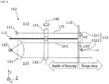
- FIG. 8 is a side view drawing illustrating an example of the optical path of the measuring light and returning light of the laser device 102.
- the side view drawing of FIG. 8 corresponds to the perspective view drawing of FIG. 3 .
- the optical axis of the measurement light 125 is shifted close to the light receiver 160 by the optical axis shift part 152.
- the perspective parallax is reduced due to the measuring light 125 being emitted to the range area from a position close to the central axis (specifically, the central axis of the condenser lens 161) of the light receiver 160. Furthermore, stray light interference is also decreased, as the measuring light 125 and the returning light 165 are processed respectively by the light transmitting region 113 and the light receiving region 114 separated from each other by the shielding plate 112.
- the position (in other words, the disposition height of the second reflection part 1512 and 1522) where the optical axis shift part 151 and 152 emits the measuring light 125 may be the same as the disposition height of the central axis (in other words, the central axis of the light receiver 160) of the condenser lens 161, and may also be different.
- the disposition height of the second reflection part 1512 and 1522 and the height of the optical axis of the light receiver 160 is the same, the perspective parallax can be minimized, and also, in a case where it is different, inconveniences where the second reflection part 1512 and 1522 becomes an obstacle, and the input amount to the light receiving element 162 of the returning light 165 is decreased can be reduced.
- the second reflection part 1512 and 1522 may be positioned closer to the light receiver 160 than the shielding plate 112. Accordingly, the optical axis shift part 151 and 152 will emit the measuring light 125 from a height lower than the disposition height of the shielding plate 112. In other words, stray light interference is decreased by the shielding plate 112, while the measuring light 125 can be emitted from a position where the optical path of the light receiver 160 of the returning light is not blocked by the shielding plate 112.
- optical axis shift part 151 and 152 may also be provided within the thickness of the housing window 115.
- the optical axis shift part 151 and 152 may be embedded on the housing window 115. Accordingly, results can be attained whereby perspective parallax is reduced and stray light interference is decreased.
- FIG. 9 is a cutout perspective view drawing illustrating an example configuration of a laser device 103 according to the second embodiment of the present invention.
- the shape of a first reflection part 1531 and a second reflection part 1532 configured of an optical axis shift part 153 has been changed, consequent upon changes to the shape of the housing window 116.
- the laser device 103 is the same as the laser device 101, with the exception of the point where the shape of the housing window 116 and the optical axis shift part 153 has been changed.
- FIG. 10 is a perspective view drawing illustrating an example of a detailed configuration of the optical axis shift part 153.
- the first reflection part 1531 of the optical axis shift part 153 is disposed to curve along the housing window 116, in a position where the measuring light 125 intersects after being reflected by the light transmitting mirror 141.
- the first reflection part 1531 is provided on the height of the central axis of the light transmitter 120, on the outer surface of the housing window 116, and it may have a long mirror, having a reflective surface, forming an outer surface for the housing window 116 at a 45-degree angle at any cross-section including the oscillating shaft 146.
- the second reflection part 1532 is disposed in a position parallel to the first reflection part 1531, and at a height closer than the light receiver 160. Specifically, the second reflection part 1532 is provided parallel to the first reflection part 1531, and at a position lower than the first reflection part 1531, and it may have a long mirror, having a reflective surface, forming an outer surface for the housing window 116 at a 135-degree angle at any cross-section including the oscillating shaft 146.
- the first reflection part 1531 and the second reflection part 1532 may, for example, be held at each end by a holding member (not illustrated) provided on the housing 111, and may be fixed in the aforementioned position of the housing window 116.
- the optical axis of the measuring light 125 after being reflected by the light transmitting mirror 141 is bent in a direction parallel to the outer surface of the housing window 116 by the first reflection part 1531, and is once again bent and emitted in a direction parallel to the optical axis of the original measuring light 125 by the second reflection part 1532.
- the optical axis of the measuring light 125 is shifted to a height close to the light receiver 160 (specifically, the central axis of the light receiver 160) by the optical axis shift part 153, as illustrated in FIG. 9 .
- the optical path of the measuring light and the returning light illustrated in FIG. 10 is compatible with the optical path of the measuring light 125 and the returning light 165 at any cross-section including the oscillating shaft 146.
- the optical axis shift part can be configured of a prism in place of a mirror. In the following, a modified example of such an optical axis shift part will be described.
- FIG. 11 is a perspective view drawing illustrating an example of a detailed configuration of an optical axis shift part 154 according to the modified example.
- the optical axis shift part 154 is configured of one prism curved along the housing window 116, and a first reflection part 1541 and a second reflection part 1542 are a pair of reflective surfaces provided on the prism.
- the first reflection part 1541 is disposed in a position where the housing window 116 and the measuring light 125 intersect. Specifically, the reflective surface as the first reflection part 1541 may form the outer surface of the housing window 116 at a 45-degree angle at any cross-section including the oscillating shaft 146.
- the second reflection part 1542 is disposed in a position parallel to the first reflection part 1541, and at a height closer than the light receiver 160.
- the reflective surface as the second reflection part 1542 may form the outer surface of the housing window 115 at a 135-degree angle at any cross-section including the oscillating shaft 146.
- the optical axis shift part 154 may, for example, be adhered to the housing window 115, or be held at each end by a holding member (not illustrated) provided on the housing 111, and may be fixed in the aforementioned position.
- the optical axis of the measuring light 125 after being reflected by the light transmitting mirror 141 is bent in a direction parallel to the outer surface of the housing window 116 by the first reflection part 1541, and is once again bent and emitted in a direction parallel to the optical axis of the original measuring light 125 by the second reflection part 1542.
- the optical axis of the measuring light 125 is shifted to a height close to the light receiver 160 (specifically, the central axis of the light receiver 160) by the optical axis shift part 154, as illustrated in FIG. 11 .
- the optical path of the measuring light and the returning light illustrated in FIG. 11 is compatible with the optical path of the measuring light 125 and the returning light 165 at any cross-section including the oscillating shaft 146.
- horizontal parallax which can occur due to the laser device 101 and 102 can be cancelled by the laser device 103 and 104.
- horizontal parallax will be described, and results of the laser device 103 and 104 will be further described.
- FIG. 12 is a top view drawing illustrating an example of the optical path of the measuring light of the laser device 101 and 102.
- the optical axis shift part 151 and 152 is provided on the flat board housing window 115.
- the measuring light 125a input perpendicular to the optical axis shift part 151 and 152 from the light transmitting mirror 141 is emitted straight in the top view.
- a measuring light 125b and 125c input diagonally to the optical axis shift part 151 and 152 is shifted and emitted in a y-axis direction, by deviating to a y-axis direction between the first reflection part 1511 and the second reflection part 1512, and between the first reflection part 1512 and the second reflection part 1522 respectively.
- the optical axis of the measuring light 125 is shifted to a greatly different y-axis direction according to emitting direction by the optical axis shift part 151 and 152.
- the optical axis shift of the measuring light 125 that occurs due to the greatly different y-axis direction due to the emitting direction is referred to as the horizontal parallax.
- the horizontal parallax similar to the aforementioned perspective parallax, is a possible cause for measurement errors due to deviation of the condensing point.
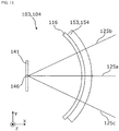
- FIG. 13 is a top view drawing illustrating an example of the optical path of the measuring light of the laser device 103 and 104.
- the optical axis shift part 153 and 154 are provided to curve around the cylindrical side surface shape housing window 116 as the center of the oscillating shaft 146.
- horizontal parallax does not occur in the optical axis shift part 153 and 154 as the measuring light 125 is input perpendicular, regardless of the emitting direction.
- the housing window 116 does not have an exactly cylindrical side surface shape as the center of the oscillating shaft 146, and also the oscillating shaft 146 side need only have curvature constituting a concave surface. Accordingly, horizontal parallax can be reduced to an extent.
- FIG. 14 is a side view drawing illustrating an example of the optical path of the measuring light and returning light of a laser device 105 according to the third embodiment of the present invention.
- an optical axis shift part 155 of the laser device 105 is different in comparison with the laser device 101 of FIG. 7 .
- the components are the same as the laser device 101, with the exception of the optical axis shift part 155 in the laser device 105.
- the optical axis shift part 155 of the laser device 105 can be configured to change the height of the emitting position of the measuring light 125.
- the configuration of the optical axis shift part 155 is not particularly limited, however, as an example, both ends of a second reflection part 1552 are held by a moveable holding member (not illustrated) provided on the housing 111, and the second reflection part 1552 may be slid along the housing window 155.
- the first reflection part 1511 may be fixedly disposed on the housing window 115.
- the height may measure the distance to a target object positioned on a plurality of different distance measurement surfaces by moving the second reflection part 1552.
Landscapes
- Engineering & Computer Science (AREA)
- Physics & Mathematics (AREA)
- Computer Networks & Wireless Communication (AREA)
- General Physics & Mathematics (AREA)
- Radar, Positioning & Navigation (AREA)
- Remote Sensing (AREA)
- Electromagnetism (AREA)
- Optical Radar Systems And Details Thereof (AREA)
- Mechanical Optical Scanning Systems (AREA)
- Measurement Of Optical Distance (AREA)
Abstract
Description
- The present invention generally relates to a laser device (measuring apparatus) for measuring distance to a target object by using light.
- Conventional measuring apparatuses measure distance to a target object by using a moveable mirror to deflect and emit a measuring light in a plurality of directions, thereby receiving the returning light of the measuring light as reflected by the target object via the moveable mirror.
- As an example, a measuring apparatus for what is called a coaxial optical system is known, whereby the measuring light and the returning light enters and exits along the same optical axis by using an optical element such as a prism or mirror and the like, aligning the central axis of a light transmitter and the central axis of a light receiver (for example, refer to patent documents 1, 2).
- Patent document 1: Japanese Patent Application Publication No.
2011-59111 - Patent document 2: Japanese Patent Application Publication No.
2012-208059 - Laser devices that employ a coaxial optical system do not have measurement errors due to a parallax of the light transmitter and the light receiver because the optical axis of the measuring light and the optical axis of the returning light are aligned, however there is a disadvantage in that it is difficult to remove stray light interference wherein stray light generated by the measuring light being diffusely reflected in the housing wraps around the light receiver. This stray light interference is a possible cause for measurement errors.
- One or more embodiments of the present invention provide a laser device for reducing the parallax of the light transmitter and the light receiver, and for decreasing stray light interference.
- According to one or more embodiments of the present invention, a laser device may comprise: a light transmitter for emitting light, a first reflector for reflecting the light, supported and oscillated by an oscillating shaft, a light receiver provided apart from the light transmitter in the direction of the oscillating shaft, an guide part for receiving the light from the first reflector and emitting from a position closer to the light receiver in the direction of the oscillating shaft, and a second reflector for reflecting the returning light from the target object of the light emitted from the guide part to the light receiver, and oscillating in sync with the first reflector.
- Accordingly, the light after being reflected by the first reflector may be shifted and emitted to a position close to the light receiver. As a result, light may be blocked between the first reflector and the second reflector, and the light and returning light may be separated, thereby decreasing the degree of wraparound of the stray light generated by the first reflector around the light receiver. Furthermore, the parallax of the light transmitter and the light receiver may be also reduced, as the emitting position of the light is brought closer to the light receiver.
- According to one or more embodiments of the present invention, the first reflector and the second reflector are disposed on a same plane, and may be supported by the same oscillating shaft and oscillated.
- Accordingly, the first reflector and the second reflector that oscillate in sync may be implemented in a relatively simple configuration.
- According to one or more embodiments of the present invention, the laser device further includes a housing, having a window for the light and the returning light to pass through, and the guide part may be provided on the window.
- Accordingly, blocking of stray light generated within the housing becomes easier, as the optical path of the light and the optical path of the returning light may be separated in the inside of the housing.
- According to one or more embodiments of the present invention, the guide part has a first reflection part and a second reflection part that are facing, and the first reflection part may be disposed in a position where the window and the light intersect, and the second reflection part may be disposed in a position where the first reflection part is in parallel displacement close to the light receiver.
- Accordingly, the guide part may be specifically configured to emit the light input to the first reflection part from the second reflection part.
- According to one or more embodiments of the present invention, the second reflection part may be provided in the same position as the central axis of the light receiver in the direction of the oscillating shaft.
- Accordingly, the parallax of the light transmitter and the light receiver may be minimized, as the position of the emitting position of the light and central axis of the light receiver conform in the direction of the oscillating shaft.
- According to one or more embodiments of the present invention, the second reflection part may be provided in a different position to the central axis of the light receiver in the direction of the oscillating shaft.
- Accordingly, inconveniences where the second reflection part becomes an obstacle, and the input amount of the light receiver of the returning light is decreased may be reduced, as the second reflection part is disposed in a position offset from the central axis of the light receiver.
- Furthermore, the second reflection part may be moveably installed in the direction of the oscillating shaft.
- Accordingly, the distance to a target object positioned in a plurality of different distance measurement surfaces in the direction of the oscillating shaft may be measured by moving the second reflection part.
- According to one or more embodiments of the present invention, the laser device further includes a shielding plate within the housing, and the second reflection part may be positioned closer to the light receiver than the shielding plate in the direction of the oscillating shaft.
- Accordingly, wraparound of the stray light around the light receiver occurring within the housing is prevented, while the light may be emitted from a position where the optical path of the light receiver of the returning light is not blocked.
- According to one or more embodiments of the present invention, a transparent member may be provided on a planar shape parallel to the oscillating shaft.
- Accordingly, manufacture may configure the transparent member on a relatively simple flat board.
- According to one or more embodiments of the present invention, the transparent member may be provided in a cylindrical shape as the center of the oscillating shaft.
- Accordingly, deviation may be minimized in the plane where the resultant light, returning light, and oscillating shaft bisect due to the guide part.
- According to one or more embodiments of the present invention, a laser device may comprise a transmitter that emits a light, a first reflector that pivotally reflects the light by a shaft, a light receiver provided apart from the transmitter in a first direction parallel to the shaft, a guide part that receives the light from the first reflector and changes a direction of the light in the first direction, and a second reflector that reflects a returning light from an object and pivots in sync with the first reflector.
- The laser device according to one or more embodiments of the present invention may reduce the parallax of the light transmitter and the light receiver, and decrease stray light interference.
-
-
FIG. 1 is a cutout perspective view drawing illustrating one example of a configuration of the laser device according to a first embodiment of the present invention. -
FIG. 2 is a perspective view drawing illustrating one example of a detailed configuration of the optical axis shift part according to the first embodiment of the present invention. -
FIG. 3 is a perspective view drawing illustrating one example of a detailed configuration of the optical axis shift part according to the first embodiment of the present invention. -
FIG. 4 is a top view drawing illustrating one example of the optical path of the measuring light and returning light of the laser device according to comparative example 1. -
FIG. 5 is a top view drawing illustrating one example of the optical path of the measuring light and returning light of the laser device according to comparative example 2. -
FIG. 6 is a side view drawing illustrating one example of the optical path of the measuring light and returning light of the laser device according to comparative example 3. -
FIG. 7 is a side view drawing illustrating one example of the optical path of the measuring light and returning light of the laser device according to the first embodiment of the present invention. -
FIG. 8 is a side view drawing illustrating one example of the optical path of the measuring light and returning light of the laser device according to the first embodiment of the present invention. -
FIG. 9 is a cutout perspective view drawing illustrating one example configuration of the laser device according to a second embodiment of the present invention. -
FIG. 10 is a perspective view drawing illustrating one example of a detailed configuration of the optical axis shift part according to the second embodiment of the present invention. -
FIG. 11 is a perspective view drawing illustrating one example of a detailed configuration of the optical axis shift part according to the second embodiment of the present invention. -
FIG. 12 is a top view drawing illustrating one example of the optical path of the measuring light of the laser device according to the first embodiment of the present invention. -
FIG. 13 is a top view drawing illustrating one example of the optical path of the measuring light of the laser device according to the second embodiment of the present invention. -
FIG. 14 is a side view drawing illustrating an example of the optical path of the measuring light and returning light of the laser device according to a third embodiment of the present invention. - Embodiments of the present invention will be described in detail with reference to drawings.
- In the following description of embodiments of the invention, numerous specific details are set forth in order to provide a more thorough understanding of the invention. However, it will be apparent to one of ordinary skill in the art that the invention may be practiced without these specific details. In other instances, well-known features have not been described in detail to avoid obscuring the invention.
- In addition, all drawings referred to in the following are schematic diagrams, and are not necessarily exactly as illustrated. In each drawing, configurations that are substantially the same are denoted by the same reference numerals, and repeated descriptions are omitted or simplified.
- Furthermore, the terms parallel and perpendicular as used in the following should be interpreted as approximately parallel and approximately perpendicular respectively. These terms denote being parallel and perpendicular with regard to design, and realistic measuring errors that occur due to member shape or assembly in the present laser device may be included.
- The laser device according to a first embodiment of the present invention is a laser device for measuring a distance to a target object, by moving a measurement light that is emitted from a light transmitter by a light transmitting mirror (first reflector), scanning the range area, and receiving a returning light of the measuring light from the target object by a light receiver via a light receiving mirror (second reflector). The laser device may be called a measuring apparatus. The laser device separates the optical path of the measuring light and the optical path of the returning light that is reflected by the oscillating mirror, decreasing stray light interference, while an optical axis shift part (guide part) is provided for shifting the optical axis of the measuring light close to the light receiver in the latter stage of the oscillating mirror.
- First, the laser device configuration according to the first embodiment of the present invention will be described.
-
FIG. 1 is a cutout perspective view drawing illustrating one example of a configuration of thelaser device 101. - As illustrated in
FIG. 1 , thelaser device 101 is provided with ahousing 111, alight transmitter 120, adeflection part 140, an opticalaxis shift part 151, alight receiver 160, and acontrol part 190. - The
housing 111 is a box configuring the exterior of thelaser device 101, and it houses thelight transmitter 120, thedeflection part 140, thelight receiver 160, and thecontrol part 190. Thehousing 111 may, for example, be configured by resin or metal. Alight transmitting region 113 and alight receiving region 114 is partitioned by ashielding plate 112 in the internal space of thehousing 111. Thelight transmitting region 113 is a region where primarily a measuring light 125 passes through, and thelight receiving region 114 is a region where primarily a returning light 165 passes through. - The internal space and the external space of the housing 111 (in short, the range area) is divided, while a
housing window 115 is provided, configured of a transparent member where the measuringlight 125 and the returning light 165 pass through. Thehousing window 115 may, for example, be a flat board made of resin or glass. - The
light transmitter 120 is an optical system for emitting the measuring light 125, and has alight source 121. Thelight source 121 may, for example, be configured of a laser diode. Thelight transmitter 120 may have acollimating lens 122 for collimating the measuring light 125, and may have a slit (not illustrated) for regulating the emitting direction of the measuringlight 125. - Here, the optical axis of the measuring light 125 that faces a light transmitting mirror (first reflector) 141 emitted from the
light transmitter 120 is defined as the central axis of thelight transmitter 120. For the convenience of explanation, the direction of the central axis of thelight transmitter 120 will be referred to as the y-axis. - The
deflection part 140 scans the range area using the measuring light 125 that is emitted from thelight transmitter 120, and is an optical system including a moveable mirror for guiding the returning light 165 from the target object in the range area to thelight receiver 160. Thedeflection part 140 is supported by anoscillating shaft 146, and has thelight transmitting mirror 141 and a light receiving mirror (second reflector) 142 for oscillating due to torque applied by anactuator 143. - The
light transmitting mirror 141 and thelight receiving mirror 142 may, for example, be configured of a metal film mirror, and may also be disposed on the same plane. Theoscillating shaft 146 may, for example, be formed by punching through the thin metal film. For the convenience of explanation, a direction parallel to theoscillating shaft 146 shall be referred to as the z-axis, and the position of the z-axis direction will be referred to as the height. - The reverse of each of the
light transmitting mirror 141 and the light receiving mirror 142 (opposite surface of the reflective surface) may, for example, be fixed to theoscillating shaft 146 by an adhesive or the like, and further, may be fixed to thehousing 111 via a fixing part (not illustrated) provided on the upper and lower ends of theoscillating shaft 146. - The
actuator 143, as an example, may be an actuator using electromagnetic force, electrostatic force, or piezoelectric displacement as the torque source. For example, due to theactuator 143 generating cyclic torque, resonance occurs in theoscillating shaft 146 as a torsion bar, and thelight transmitting mirror 141 and thelight receiving mirror 142 oscillate around the z-axis. - The
light transmitting mirror 141 scans the range area with the measuring light 125 from thelight transmitter 120 by oscillating. - The optical
axis shift part 151 receives the measuring light 125 after being reflected in thelight transmitting mirror 141, and is an optical system for emitting the received measuring light 125 from a close height by thelight receiver 160. The opticalaxis shift part 151 may, for example, be configured of afirst reflection part 1511 and asecond reflection part 1512 that are facing, and may be provided on thehousing window 115. Detailed configuration of the opticalaxis shift part 151 will be described later. - The measuring light 125 emitted from the optical
axis shift part 151 arrives at the target object (not illustrated) within the range area, and is diffusely reflected by the target object. - With regard to the measuring light 125 that is diffusely reflected by the target object, the returning light 165 that returns towards the
laser device 101 passes through thehousing window 115 of thelaser device 101, and is input to the inside of thehousing 111. Thelight receiving mirror 142 reflects the returning light 165 to thelight receiver 160. - The
light receiver 160 is an optical system for exchanging the returning light 165 reflected in thelight receiving mirror 142 to a received signal, and has alight receiving element 162. Thelight receiving element 162 may, for example, be configured of an avalanche photodiode. Thelight receiver 160 may have acondenser lens 161 for condensing the returning light 165 to thelight receiving element 162, and may have a band-pass filter (not illustrated) for removing wavelength noise light other than the measuringlight 125. Thelight receiver 160 is provided apart from thelight transmitter 120 in a height wise direction. - Here, the optical axis of light input to the light receiver from the
light receiving mirror 142 and condensed in thelight receiving element 162 is defined as the central axis of thelight receiver 160. The central axis of thelight receiver 160 may, for example, be the central axis of thecondenser lens 161, and may be parallel to the central axis of thelight transmitter 120. - The
control part 190 is a controller for controlling distance measurement operation in thelaser device 101. Thecontrol part 190 drives thelight source 121 and theactuator 143, and calculates the distance to the target object from thelaser device 101 by processing the received signal from thelight receiving element 162. - The
control part 190, for example, may be implemented by a combination of software function, carried out by a drive circuit for supplying a drive signal to thelight source 121 and theactuator 143, a hardware function such as a signal processing circuit for receiving and processing a signal from thelight receiving element 162, and a microcomputer executing a predetermined program. - The
control part 190, specifically, based on phase contrast between the received signal from thelight receiving element 162 and the drive signal supplied to thelight source 121, round trip time from thelaser device 101 of the measuring light 125 to the target object is requested, and the distance to the target object may be calculated. Furthermore, thecontrol part 190 may specify the direction of the target object within the range area from the angle of rotation (hereinafter referred to as the inclination) of around theoscillating shaft 146 of thelight transmitting mirror 141. - Next, configurations of the optical
axis shift part 151 will be described. -
FIG. 2 is a perspective view drawing illustrating an example of a detailed configuration of the opticalaxis shift part 151. - As illustrated in
FIG. 2 , thefirst reflection part 1511 of the opticalaxis shift part 151 is disposed in a position where thehousing window 115 and the measuring light 125 intersect. Specifically, thefirst reflection part 1511 is provided on the height of the central axis of thelight transmitter 120, on the outer surface of thehousing window 115, and it may have a long mirror, having a reflective surface, forming an outer surface for thehousing window 115 at a 45-degree angle. - Furthermore, the
second reflection part 1512 is disposed in a position displaced parallel to thefirst reflection part 1511, close to thelight receiver 160. Specifically, thesecond reflection part 1512 is provided parallel to thefirst reflection part 1511 of the outer surface of thehousing window 115, and on a lower position than thefirst reflection part 1511, and it may have a long mirror, having a reflective surface, forming an outer surface for thehousing window 115 at a 135-degree angle. - The
first reflection part 1511 and thesecond reflection part 1512 may, for example, be held at each end by a holding member (not illustrated) provided on thehousing 111, and may be fixed in the aforementioned position of thehousing window 115. - Accordingly, the optical axis of the measuring light 125 after being reflected by the
light transmitting mirror 141 is bent in a direction parallel to the outer surface of thehousing window 115 by thefirst reflection part 1511, and is once again bent and emitted in a direction parallel to the optical axis of theoriginal measuring light 125 by thesecond reflection part 1512. In other words, the optical axis of the measuringlight 125 is shifted to a height close to the light receiver 160 (specifically, the central axis of the light receiver 160) by the opticalaxis shift part 151, as illustrated inFIG. 1 . - The optical axis shift part can be configured of a prism in place of a mirror. In the following, a modified example of such an optical axis shift part will be described.
-
FIG. 3 is a perspective view drawing illustrating an example of a detailed configuration of the opticalaxis shift part 152 according to the modified example. - As illustrated in
FIG. 3 , the opticalaxis shift part 152 is configured of one prism, and afirst reflection part 1521 and asecond reflection part 1522 are a pair of reflective surfaces provided on the prism. - The
first reflection part 1521 is disposed in a position where thehousing window 115 and the measuring light 125 intersect. Specifically, the reflective surface as thefirst reflection part 1521 may form the outer surface of thehousing window 115 at a 45-degree angle. - Furthermore, the
second reflection part 1522 is disposed in a position displaced parallel to thefirst reflection part 1521, close to thelight receiver 160. Specifically, the reflective surface as thesecond reflection part 1522 may form the outer surface of thehousing window 115 at a 135-degree angle. - The optical
axis shift part 152 may, for example, be adhered to thehousing window 115, or be held at each end by a holding member (not illustrated) provided on thehousing 111, and may be fixed in the aforementioned position. - Accordingly, the optical axis of the measuring light 125 after being reflected by the
light transmitting mirror 141 is bent in a direction parallel to the outer surface of thehousing window 115 by thefirst reflection part 1521, and is once again bent and emitted in a direction parallel to the optical axis of theoriginal measuring light 125. In other words, the optical axis of the measuringlight 125 is shifted to a height close to the light receiver 160 (specifically, the central axis of the light receiver 160) by the opticalaxis shift part 152, as illustrated inFIG. 3 . - Results obtained by the
laser device 101 configured as per the abovementioned will be described based on a comparison of a plurality of comparative examples. -
FIG. 4 is a top view drawing illustrating an example of the optical path of the measuring light and the returning light of alaser device 801 according to comparative example 1. Thelaser device 801 is an example of a coaxial optical system laser device stated in the related art. In thelaser device 801, the measuring light 125 emitted from thelight source 121 and the returning light 165 condensed in thelight receiving element 162 by thecondenser lens 161 are overlaid on the same optical axis by aperforated mirror 158, and is moved in a plurality of directions by amoveable mirror 148, and then emitted to the range area from thehousing window 115. As a result, there is a concern that in thelaser device 801, astray light 129 generated by the inner surface of theperforated mirror 158, themoveable mirror 148 and thehousing window 115 cannot be separated from the returninglight 165. -
FIG. 5 is a top view drawing illustrating an example of the optical path of the measuring light and the returning light of alaser device 802 according to comparative example 2. Thelaser device 802 is an example of a coaxial optical system laser device stated in the related art. In thelaser device 802, the measuring light 125 emitted from thelight source 121 and the returning light 165 condensed in thelight receiving element 162 by thecondenser lens 161 are overlaid on the same optical axis by amirror 159, is moved in a plurality of directions by themoveable mirror 148, and then emitted to the range area from thehousing window 115. As a result, in thelaser device 802, there is a concern that thestray light 129 generated by the inner surface of themirror 159, themoveable mirror 148 and thehousing window 115 cannot be separated from the returninglight 165. - Accordingly, the inventor has examined a separating optical system laser device for processing the measuring light and the returning light through a separated space within the housing of both, without being disposed on the same optical axis within the housing.
-
FIG. 6 is a side view drawing illustrating an example of the optical path of the measuring light and returning light of alaser device 803 according to comparative example 3. In thelaser device 803, thelight transmitting region 113 and alight receiving region 114 is partitioned by ashielding plate 112 in the inside of the housing. Thelight transmitting mirror 141 and thelight receiving mirror 142 are provided apart in a height-wise direction, and theshielding plate 112 is also inserted between thelight transmitting mirror 141 and thelight receiving mirror 142, excluding the vicinity of theoscillating shaft 146. - In the
light transmitting region 113, the measuring light 125 emitted from thelight source 121 is moved in a plurality of directions by thelight transmitting mirror 141, and then emitted to the range area from thehousing window 115. Furthermore, in thelight receiving region 114, a returning light 165a and 165b input from thehousing window 115 is guided to thecondenser lens 161 via thelight receiving mirror 142, and condensed in thelight receiving element 162. Here, the returning light 165a and 165b is the returning light from the long distance target object and the close distance target object respectively. - In this way, in the
laser device 803, the measuringlight 125 and the returning light 165a and 165b are processed respectively by thelight transmitting region 113 and thelight receiving region 114 separated from each other by the shieldingplate 112. As a result, even in a case where thestray light 129 occurs, wraparound of thestray light 129 around thelight receiving element 162 can be prevented. - However, in the
laser device 803, a parallax corresponding to the distance to the target object will occur as a result of the measuring light 125 being disposed apart from the central axis (in other words, the central axis of the light receiver 160) of thecondenser lens 161. - Specifically, as illustrated in
FIG. 6 , the condensing point deviates a distance d, due to the returning light 165a from the long distance target object and the returning light 165b of the close distance target object being input to thelaser device 803 through a different input angle to each other. Input angle deviation of the returning light 165 corresponding to the target object distance is referred to as the perspective parallax. For example, when thecondenser lens 161 and thelight receiving element 162 are disposed in combination with the returning light 165a from the long distance target object, the returning light 165b from the close distance target object will not be accurately condensed in thelight receiving element 162 as a result of the perspective parallax, and may become a cause of distance measurement errors. - Here, the present inventor proposes a
laser device axis shift part laser device 803 according to comparative example 3. The aforementioned stray light interference and perspective parallax may be reduced by thelaser device -
FIG. 7 is a side view drawing illustrating an example of the optical path of the measuring light and returning light of thelaser device 101. The side view drawing ofFIG. 7 corresponds to the perspective view drawing ofFIG. 2 . In thelaser device 101, as described above, the optical axis of the measuringlight 125 is shifted close to thelight receiver 160 by the opticalaxis shift part 151. -
FIG. 8 is a side view drawing illustrating an example of the optical path of the measuring light and returning light of thelaser device 102. The side view drawing ofFIG. 8 corresponds to the perspective view drawing ofFIG. 3 . In thelaser device 102, as described above, the optical axis of themeasurement light 125 is shifted close to thelight receiver 160 by the opticalaxis shift part 152. - In either the
laser device light receiver 160. Furthermore, stray light interference is also decreased, as the measuringlight 125 and the returning light 165 are processed respectively by thelight transmitting region 113 and thelight receiving region 114 separated from each other by the shieldingplate 112. - In addition, the position (in other words, the disposition height of the
second reflection part 1512 and 1522) where the opticalaxis shift part condenser lens 161, and may also be different. In a case where the disposition height of thesecond reflection part light receiver 160 is the same, the perspective parallax can be minimized, and also, in a case where it is different, inconveniences where thesecond reflection part light receiving element 162 of the returning light 165 is decreased can be reduced. - Furthermore, the
second reflection part light receiver 160 than the shieldingplate 112. Accordingly, the opticalaxis shift part shielding plate 112. In other words, stray light interference is decreased by the shieldingplate 112, while the measuring light 125 can be emitted from a position where the optical path of thelight receiver 160 of the returning light is not blocked by the shieldingplate 112. - Furthermore, in the aforementioned, an example where the optical
axis shift part housing window 115 was described, however the opticalaxis shift part housing window 115. In other words, the opticalaxis shift part housing window 115. Accordingly, results can be attained whereby perspective parallax is reduced and stray light interference is decreased. - A second embodiment of the present invention will be described in detail with reference to drawings.
-
FIG. 9 is a cutout perspective view drawing illustrating an example configuration of alaser device 103 according to the second embodiment of the present invention. - As illustrated in
FIG. 9 , with regard to thelaser device 103, the point where ahousing window 116 is provided on a cylindrical shape as the center of theoscillating shaft 146 - is different in comparison with the
laser device 101 ofFIG. 1 . The shape of afirst reflection part 1531 and asecond reflection part 1532 configured of an opticalaxis shift part 153 has been changed, consequent upon changes to the shape of thehousing window 116. Thelaser device 103 is the same as thelaser device 101, with the exception of the point where the shape of thehousing window 116 and the opticalaxis shift part 153 has been changed. - Configurations of the optical
axis shift part 153 will be described in detail. -
FIG. 10 is a perspective view drawing illustrating an example of a detailed configuration of the opticalaxis shift part 153. - As illustrated in
FIG. 10 , thefirst reflection part 1531 of the opticalaxis shift part 153 is disposed to curve along thehousing window 116, in a position where the measuringlight 125 intersects after being reflected by thelight transmitting mirror 141. Specifically, thefirst reflection part 1531 is provided on the height of the central axis of thelight transmitter 120, on the outer surface of thehousing window 116, and it may have a long mirror, having a reflective surface, forming an outer surface for thehousing window 116 at a 45-degree angle at any cross-section including theoscillating shaft 146. - Furthermore, the
second reflection part 1532 is disposed in a position parallel to thefirst reflection part 1531, and at a height closer than thelight receiver 160. Specifically, thesecond reflection part 1532 is provided parallel to thefirst reflection part 1531, and at a position lower than thefirst reflection part 1531, and it may have a long mirror, having a reflective surface, forming an outer surface for thehousing window 116 at a 135-degree angle at any cross-section including theoscillating shaft 146. - The
first reflection part 1531 and thesecond reflection part 1532 may, for example, be held at each end by a holding member (not illustrated) provided on thehousing 111, and may be fixed in the aforementioned position of thehousing window 116. - Accordingly, the optical axis of the measuring light 125 after being reflected by the
light transmitting mirror 141 is bent in a direction parallel to the outer surface of thehousing window 116 by thefirst reflection part 1531, and is once again bent and emitted in a direction parallel to the optical axis of theoriginal measuring light 125 by thesecond reflection part 1532. In other words, the optical axis of the measuringlight 125 is shifted to a height close to the light receiver 160 (specifically, the central axis of the light receiver 160) by the opticalaxis shift part 153, as illustrated inFIG. 9 . - In the
laser device 103, the optical path of the measuring light and the returning light illustrated inFIG. 10 is compatible with the optical path of the measuringlight 125 and the returning light 165 at any cross-section including theoscillating shaft 146. - The optical axis shift part can be configured of a prism in place of a mirror. In the following, a modified example of such an optical axis shift part will be described.
-
FIG. 11 is a perspective view drawing illustrating an example of a detailed configuration of an opticalaxis shift part 154 according to the modified example. - As illustrated in
FIG. 11 , the opticalaxis shift part 154 is configured of one prism curved along thehousing window 116, and a first reflection part 1541 and asecond reflection part 1542 are a pair of reflective surfaces provided on the prism. - The first reflection part 1541 is disposed in a position where the
housing window 116 and the measuring light 125 intersect. Specifically, the reflective surface as the first reflection part 1541 may form the outer surface of thehousing window 116 at a 45-degree angle at any cross-section including theoscillating shaft 146. - Furthermore, the
second reflection part 1542 is disposed in a position parallel to the first reflection part 1541, and at a height closer than thelight receiver 160. Specifically, the reflective surface as thesecond reflection part 1542 may form the outer surface of thehousing window 115 at a 135-degree angle at any cross-section including theoscillating shaft 146. - The optical
axis shift part 154 may, for example, be adhered to thehousing window 115, or be held at each end by a holding member (not illustrated) provided on thehousing 111, and may be fixed in the aforementioned position. - Accordingly, the optical axis of the measuring light 125 after being reflected by the
light transmitting mirror 141 is bent in a direction parallel to the outer surface of thehousing window 116 by the first reflection part 1541, and is once again bent and emitted in a direction parallel to the optical axis of theoriginal measuring light 125 by thesecond reflection part 1542. In other words, the optical axis of the measuringlight 125 is shifted to a height close to the light receiver 160 (specifically, the central axis of the light receiver 160) by the opticalaxis shift part 154, as illustrated inFIG. 11 . - In the
laser device 104, the optical path of the measuring light and the returning light illustrated inFIG. 11 is compatible with the optical path of the measuringlight 125 and the returning light 165 at any cross-section including theoscillating shaft 146. - In this way, even in the
laser device light 125 and the returninglight 165 of the side-view (cross-section view) is disposed equally to thelaser device - Moreover, horizontal parallax which can occur due to the
laser device laser device laser device -
FIG. 12 is a top view drawing illustrating an example of the optical path of the measuring light of thelaser device laser device axis shift part board housing window 115. As a result, the measuringlight 125a input perpendicular to the opticalaxis shift part light transmitting mirror 141 is emitted straight in the top view. On the other hand, a measuring light 125b and 125c input diagonally to the opticalaxis shift part first reflection part 1511 and thesecond reflection part 1512, and between thefirst reflection part 1512 and thesecond reflection part 1522 respectively. - In this way, the optical axis of the measuring
light 125 is shifted to a greatly different y-axis direction according to emitting direction by the opticalaxis shift part -
FIG. 13 is a top view drawing illustrating an example of the optical path of the measuring light of thelaser device laser device axis shift part housing window 116 as the center of theoscillating shaft 146. As a result, horizontal parallax does not occur in the opticalaxis shift part light 125 is input perpendicular, regardless of the emitting direction. - In addition, the
housing window 116 does not have an exactly cylindrical side surface shape as the center of theoscillating shaft 146, and also theoscillating shaft 146 side need only have curvature constituting a concave surface. Accordingly, horizontal parallax can be reduced to an extent. - A third embodiment of the present invention will be described specifically with reference to drawings.
-
FIG. 14 is a side view drawing illustrating an example of the optical path of the measuring light and returning light of alaser device 105 according to the third embodiment of the present invention. - As illustrated in
FIG. 14 , an opticalaxis shift part 155 of thelaser device 105 is different in comparison with thelaser device 101 ofFIG. 7 . The components are the same as thelaser device 101, with the exception of the opticalaxis shift part 155 in thelaser device 105. - The optical
axis shift part 155 of thelaser device 105 can be configured to change the height of the emitting position of the measuringlight 125. The configuration of the opticalaxis shift part 155 is not particularly limited, however, as an example, both ends of asecond reflection part 1552 are held by a moveable holding member (not illustrated) provided on thehousing 111, and thesecond reflection part 1552 may be slid along thehousing window 155. Thefirst reflection part 1511 may be fixedly disposed on thehousing window 115. - Accordingly, the height may measure the distance to a target object positioned on a plurality of different distance measurement surfaces by moving the
second reflection part 1552. - Although the disclosure has been described with respect to only a limited number of embodiments, those skilled in the art, having benefit of this disclosure, will appreciate that various other embodiments may be devised without departing from the scope of the present invention. Accordingly, the scope of the invention should be limited only by the attached claims.
- 101, 102, 103, 104, 105, 801, 802, 803
- Laser device
- 111
- Housing
- 112
- Shielding Plate
- 113
- Light Transmitting Region
- 114
- Light Receiving Region
- 115, 116
- Housing Window
- 120
- Light Transmitter
- 121
- Light Source
- 122
- Collimating Lens
- 125, 125a, 125b, 125c
- Measuring Light
- 129
- Stray Light
- 140
- Deflection Part
- 141
- Light Transmitting Mirror (First reflector)
- 142
- Light Receiving Mirror (Second reflector)
- 143
- Actuator
- 146
- Oscillating Shaft
- 148
- Moveable Mirror
- 151, 152, 153, 154, 155
- Optical Axis Shift Part (Guide part)
- 158
- Perforated Mirror
- 159
- Mirror
- 160
- Light Receiver
- 161
- Condenser Lens
- 162
- Light Receiving Element
- 165, 165a, 165b
- Returning Light
- 190
- Control Part
- 1511, 1521, 1531, 1541
- First Reflection Part
- 1512, 1522, 1532, 1542, 1552
- Second Reflection Part
Claims (15)
- A laser device, comprising:a transmitter (120) that emits a light;a first reflector (141) that pivotally reflects the light by a shaft (146);a light receiver (160) provided apart from the transmitter in a first direction parallel to the shaft (146);a guide part (151-155) that receives the light from the first reflector (141) and changes a direction of the light in the first direction; anda second reflector (142) that reflects a returning light from an object and pivots in sync with the first reflector (141).
- The laser device according to claim 1, wherein the first reflector (141) and the second reflector (142) are disposed on a same plane.
- The laser device according to claim 1 or 2, further comprising:a housing (111) comprising a window (115, 116) whereby the light and the returning light pass through,wherein the guide part (151-155) is disposed on the window.
- The laser device according to claim 3,wherein the guide part comprises a first reflection part (1511, 1521, 1531, 1541) and a second reflection part (1512, 1522, 1532, 1542, 1552),wherein the first reflection part is disposed in a first position, andwherein the second reflection part is disposed in a second position near the light receiver in the first direction.
- The laser device according to claim 4, wherein the first position is a position where the window (115, 116) and the light intersect.
- The laser device according to claim 4 or 5, wherein the first reflection part is parallel to the second reflection part in a second direction orthogonal to the first direction.
- The laser device according to any one of claims 4 to 6, wherein the second reflection part is disposed on a central axis of the light receiver (160) in the first direction.
- The laser device according to claim 7,wherein the light receiver (160) comprises a light receiving element (162), andwherein the central axis of the light receiver is a center of the light input to the light receiver (160) from the second reflector (142) and condensed in the light receiving element (162).
- The laser device according to any one of claims 4 to 6, wherein the second reflection part is disposed on a position different from a central axis of the light receiver (160) in the first direction.
- The laser device according to claim 9,wherein the light receiver (160) comprises a light receiving element (162), andwherein the central axis of the light receiver is an optical axis of light input to the light receiver (160) from the second reflector (142) and condensed in the light receiving element (162).
- The laser device according to any one of claims 4 to 6, wherein the second reflection part (1552) is moveable in the first direction.
- The laser device according to any one of claims 4 to 11,wherein the housing (111) comprises a shielding plate (112), andwherein the second reflection part is disposed near the light receiver (160) than the second reflector (142) in the first direction.
- The laser device according to any one of claims 3 to 12, wherein the window (115) is a planar shape parallel to the first direction.
- The laser device according to any one of claims 3 to 12, wherein the window (116) is a cylindrical shape of which a center is the shaft (146).
- The laser device according to any one of claims 4 to 14,wherein the first reflection part comprises a reflective surface that forms the window (115, 116) at a 45-degree angle, andwherein the second reflection part comprises a reflective surface that forms the window (115, 116) at a 135-degree angle.
Applications Claiming Priority (1)
| Application Number | Priority Date | Filing Date | Title |
|---|---|---|---|
| JP2015217832A JP6672715B2 (en) | 2015-11-05 | 2015-11-05 | measuring device |
Publications (2)
| Publication Number | Publication Date |
|---|---|
| EP3165942A1 true EP3165942A1 (en) | 2017-05-10 |
| EP3165942B1 EP3165942B1 (en) | 2020-06-10 |
Family
ID=57233351
Family Applications (1)
| Application Number | Title | Priority Date | Filing Date |
|---|---|---|---|
| EP16197318.5A Active EP3165942B1 (en) | 2015-11-05 | 2016-11-04 | Laser device |
Country Status (4)
| Country | Link |
|---|---|
| US (1) | US10416287B2 (en) |
| EP (1) | EP3165942B1 (en) |
| JP (1) | JP6672715B2 (en) |
| CN (1) | CN106680826B (en) |
Cited By (5)
| Publication number | Priority date | Publication date | Assignee | Title |
|---|---|---|---|---|
| EP3447524A1 (en) * | 2017-08-21 | 2019-02-27 | Yujin Robot Co., Ltd. | Compact three-dimensional scanning lidar sensor |
| US10962647B2 (en) | 2016-11-30 | 2021-03-30 | Yujin Robot Co., Ltd. | Lidar apparatus based on time of flight and moving object |
| US11579298B2 (en) | 2017-09-20 | 2023-02-14 | Yujin Robot Co., Ltd. | Hybrid sensor and compact Lidar sensor |
| US11874399B2 (en) | 2018-05-16 | 2024-01-16 | Yujin Robot Co., Ltd. | 3D scanning LIDAR sensor |
| EP4542252A1 (en) * | 2023-10-16 | 2025-04-23 | Hyundai Mobis Co., Ltd. | Device and method for detecting window contamination of lidar sensor |
Families Citing this family (12)
| Publication number | Priority date | Publication date | Assignee | Title |
|---|---|---|---|---|
| TWI490521B (en) * | 2012-11-14 | 2015-07-01 | 原相科技股份有限公司 | Proximity optical sensor and manufacturing method |
| FR3056524B1 (en) * | 2016-09-28 | 2018-10-12 | Valeo Systemes D'essuyage | DETECTION SYSTEM FOR MOTOR VEHICLE |
| CN107134094A (en) * | 2017-05-26 | 2017-09-05 | 南京联新昱科电子技术有限公司 | Laser security device and method |
| JP7066982B2 (en) * | 2017-05-30 | 2022-05-16 | 船井電機株式会社 | Optical scanning device |
| DE102017214715A1 (en) * | 2017-08-23 | 2019-02-28 | Robert Bosch Gmbh | Optical arrangement for a LiDAR system, LiDAR system and working device |
| JP6737296B2 (en) * | 2018-02-20 | 2020-08-05 | オムロン株式会社 | Object detection device |
| CN111273254B (en) * | 2018-12-04 | 2024-05-10 | 无锡驭风智研科技有限公司 | Laser radar transmitting device and laser radar |
| CN111670375A (en) * | 2019-01-09 | 2020-09-15 | 深圳市大疆创新科技有限公司 | A distance measuring device and mobile platform |
| CN114545364B (en) * | 2020-11-27 | 2025-08-08 | 上海禾赛科技有限公司 | Optical windows and lidar |
| DE112022001295T5 (en) * | 2021-04-30 | 2023-12-28 | Hesai Technology Co., Ltd. | LIGHT DETECTION DEVICE AND VEHICLES, LIDAR AND DETECTION METHOD |
| US20230025747A1 (en) * | 2021-07-26 | 2023-01-26 | Luminar, Llc | Lidar transceiver with coaxial transmit and receive path |
| JP2024101926A (en) * | 2023-01-18 | 2024-07-30 | 株式会社デンソー | Optical sensor |
Citations (8)
| Publication number | Priority date | Publication date | Assignee | Title |
|---|---|---|---|---|
| US20080007710A1 (en) * | 2004-07-22 | 2008-01-10 | B.E.A. S.A. | Door sensor system for detecting a target object |
| JP2009109310A (en) * | 2007-10-30 | 2009-05-21 | Denso Wave Inc | Laser radar apparatus |
| JP2011059111A (en) | 2009-09-05 | 2011-03-24 | Sick Ag | Optoelectronic scanner |
| US20110235018A1 (en) * | 2010-03-25 | 2011-09-29 | Hokuyo Automatic Co., Ltd. | Scanning-type distance measuring apparatus |
| JP2012208059A (en) | 2011-03-30 | 2012-10-25 | Denso Wave Inc | Laser radar device |
| US20140332676A1 (en) * | 2011-11-29 | 2014-11-13 | Valeo Schalter Und Sensoren Gmbh | Optical measuring device |
| WO2015082217A2 (en) * | 2013-12-05 | 2015-06-11 | Trimble Ab | Distance measurement instrument with scanning function |
| JP2015143620A (en) * | 2014-01-31 | 2015-08-06 | 株式会社デンソーウェーブ | laser radar device |
Family Cites Families (15)
| Publication number | Priority date | Publication date | Assignee | Title |
|---|---|---|---|---|
| JPS60211382A (en) * | 1984-04-05 | 1985-10-23 | Optic:Kk | Light wave range finder equipped with calibration optical path |
| US4916536A (en) * | 1988-11-07 | 1990-04-10 | Flir Systems, Inc. | Imaging range finder and method |
| US7187445B2 (en) * | 2001-07-19 | 2007-03-06 | Automotive Distance Control Systems Gmbh | Method and apparatus for optically scanning a scene |
| JP2003050128A (en) * | 2001-08-07 | 2003-02-21 | Sokkia Co Ltd | Distance measuring angle finder |
| DE10142425A1 (en) * | 2001-08-31 | 2003-04-17 | Adc Automotive Dist Control | scanning |
| WO2003025620A2 (en) * | 2001-08-31 | 2003-03-27 | Automotive Distance Control Systems Gmbh | Sensor device |
| JP3802394B2 (en) * | 2001-10-16 | 2006-07-26 | オムロン株式会社 | Automotive radar equipment |
| DE10351254A1 (en) * | 2003-11-03 | 2005-06-02 | Adc Automotive Distance Control Systems Gmbh | Apparatus for detecting soiling on a translucent cover in front of an optical unit |
| JP5154028B2 (en) * | 2006-04-28 | 2013-02-27 | 株式会社 ソキア・トプコン | Light wave distance meter |
| JP2008077721A (en) * | 2006-09-20 | 2008-04-03 | Funai Electric Co Ltd | Objective lens actuator and optical pickup |
| JP5598831B2 (en) * | 2007-09-05 | 2014-10-01 | 北陽電機株式会社 | Scanning distance measuring device |
| IL200904A (en) * | 2009-09-13 | 2015-07-30 | Yefim Kereth | Device for object detection and location |
| JP2011099816A (en) * | 2009-11-09 | 2011-05-19 | Sony Corp | Condenser lens and three-dimensional distance measuring device |
| JP5488099B2 (en) * | 2009-12-08 | 2014-05-14 | 株式会社デンソーウェーブ | Laser radar equipment |
| JP6198400B2 (en) * | 2013-01-31 | 2017-09-20 | 株式会社トプコン | Light wave distance meter |
-
2015
- 2015-11-05 JP JP2015217832A patent/JP6672715B2/en not_active Expired - Fee Related
-
2016
- 2016-11-04 EP EP16197318.5A patent/EP3165942B1/en active Active
- 2016-11-04 CN CN201610962336.5A patent/CN106680826B/en active Active
- 2016-11-07 US US15/345,048 patent/US10416287B2/en active Active
Patent Citations (8)
| Publication number | Priority date | Publication date | Assignee | Title |
|---|---|---|---|---|
| US20080007710A1 (en) * | 2004-07-22 | 2008-01-10 | B.E.A. S.A. | Door sensor system for detecting a target object |
| JP2009109310A (en) * | 2007-10-30 | 2009-05-21 | Denso Wave Inc | Laser radar apparatus |
| JP2011059111A (en) | 2009-09-05 | 2011-03-24 | Sick Ag | Optoelectronic scanner |
| US20110235018A1 (en) * | 2010-03-25 | 2011-09-29 | Hokuyo Automatic Co., Ltd. | Scanning-type distance measuring apparatus |
| JP2012208059A (en) | 2011-03-30 | 2012-10-25 | Denso Wave Inc | Laser radar device |
| US20140332676A1 (en) * | 2011-11-29 | 2014-11-13 | Valeo Schalter Und Sensoren Gmbh | Optical measuring device |
| WO2015082217A2 (en) * | 2013-12-05 | 2015-06-11 | Trimble Ab | Distance measurement instrument with scanning function |
| JP2015143620A (en) * | 2014-01-31 | 2015-08-06 | 株式会社デンソーウェーブ | laser radar device |
Cited By (7)
| Publication number | Priority date | Publication date | Assignee | Title |
|---|---|---|---|---|
| US10962647B2 (en) | 2016-11-30 | 2021-03-30 | Yujin Robot Co., Ltd. | Lidar apparatus based on time of flight and moving object |
| US12313742B2 (en) | 2016-11-30 | 2025-05-27 | Yujin Robot Co., Ltd. | LIDAR apparatus based on time of flight and moving object |
| US12372653B2 (en) | 2016-11-30 | 2025-07-29 | Yujin Robot Co., Ltd. | LIDAR apparatus based on time of flight and moving object |
| EP3447524A1 (en) * | 2017-08-21 | 2019-02-27 | Yujin Robot Co., Ltd. | Compact three-dimensional scanning lidar sensor |
| US11579298B2 (en) | 2017-09-20 | 2023-02-14 | Yujin Robot Co., Ltd. | Hybrid sensor and compact Lidar sensor |
| US11874399B2 (en) | 2018-05-16 | 2024-01-16 | Yujin Robot Co., Ltd. | 3D scanning LIDAR sensor |
| EP4542252A1 (en) * | 2023-10-16 | 2025-04-23 | Hyundai Mobis Co., Ltd. | Device and method for detecting window contamination of lidar sensor |
Also Published As
| Publication number | Publication date |
|---|---|
| US20170131386A1 (en) | 2017-05-11 |
| JP6672715B2 (en) | 2020-03-25 |
| US10416287B2 (en) | 2019-09-17 |
| CN106680826A (en) | 2017-05-17 |
| EP3165942B1 (en) | 2020-06-10 |
| JP2017090128A (en) | 2017-05-25 |
| CN106680826B (en) | 2019-08-06 |
Similar Documents
| Publication | Publication Date | Title |
|---|---|---|
| EP3165942B1 (en) | Laser device | |
| EP3692397B1 (en) | Coaxial setup for light detection and ranging, lidar, measurements | |
| US9348138B2 (en) | Laser processing device | |
| JP5433976B2 (en) | Ranging device | |
| EP3153877B1 (en) | Position detecting apparatus and measuring method | |
| CN107797273B (en) | Scanning mirror | |
| JP2017106833A (en) | Measuring apparatus | |
| US10634767B2 (en) | Electronic distance measuring instrument | |
| US20210190919A1 (en) | Detection system using optical scanning element with glass body and reflective member | |
| JP2022023609A (en) | Surveying device | |
| JP6330539B2 (en) | Laser scanning device | |
| WO2019208306A1 (en) | Light irradiation device and laser radar device | |
| CN111656214A (en) | LiDAR device | |
| CN111630408A (en) | Lidar device | |
| CN109765541B (en) | Scanning device and laser radar | |
| JP2017090094A (en) | Measurement device | |
| JP2010091779A (en) | Light source unit and optical scanner equipped with the same | |
| JP2014066724A (en) | Distance measuring device | |
| JP2017106745A (en) | Measurement device | |
| JP5451047B2 (en) | Optical scanning device | |
| US20220326590A1 (en) | Laser shutter unit and laser system | |
| EP4080267A1 (en) | Optical scanning device | |
| JP2015210280A (en) | Optical scanning device |
Legal Events
| Date | Code | Title | Description |
|---|---|---|---|
| PUAI | Public reference made under article 153(3) epc to a published international application that has entered the european phase |
Free format text: ORIGINAL CODE: 0009012 |
|
| STAA | Information on the status of an ep patent application or granted ep patent |
Free format text: STATUS: THE APPLICATION HAS BEEN PUBLISHED |
|
| AK | Designated contracting states |
Kind code of ref document: A1 Designated state(s): AL AT BE BG CH CY CZ DE DK EE ES FI FR GB GR HR HU IE IS IT LI LT LU LV MC MK MT NL NO PL PT RO RS SE SI SK SM TR |
|
| AX | Request for extension of the european patent |
Extension state: BA ME |
|
| STAA | Information on the status of an ep patent application or granted ep patent |
Free format text: STATUS: REQUEST FOR EXAMINATION WAS MADE |
|
| 17P | Request for examination filed |
Effective date: 20171109 |
|
| RBV | Designated contracting states (corrected) |
Designated state(s): AL AT BE BG CH CY CZ DE DK EE ES FI FR GB GR HR HU IE IS IT LI LT LU LV MC MK MT NL NO PL PT RO RS SE SI SK SM TR |
|
| GRAP | Despatch of communication of intention to grant a patent |
Free format text: ORIGINAL CODE: EPIDOSNIGR1 |
|
| STAA | Information on the status of an ep patent application or granted ep patent |
Free format text: STATUS: GRANT OF PATENT IS INTENDED |
|
| INTG | Intention to grant announced |
Effective date: 20200206 |
|
| GRAS | Grant fee paid |
Free format text: ORIGINAL CODE: EPIDOSNIGR3 |
|
| GRAA | (expected) grant |
Free format text: ORIGINAL CODE: 0009210 |
|
| STAA | Information on the status of an ep patent application or granted ep patent |
Free format text: STATUS: THE PATENT HAS BEEN GRANTED |
|
| AK | Designated contracting states |
Kind code of ref document: B1 Designated state(s): AL AT BE BG CH CY CZ DE DK EE ES FI FR GB GR HR HU IE IS IT LI LT LU LV MC MK MT NL NO PL PT RO RS SE SI SK SM TR |
|
| REG | Reference to a national code |
Ref country code: GB Ref legal event code: FG4D |
|
| REG | Reference to a national code |
Ref country code: CH Ref legal event code: EP Ref country code: AT Ref legal event code: REF Ref document number: 1279616 Country of ref document: AT Kind code of ref document: T Effective date: 20200615 |
|
| REG | Reference to a national code |
Ref country code: DE Ref legal event code: R096 Ref document number: 602016037813 Country of ref document: DE |
|
| REG | Reference to a national code |
Ref country code: IE Ref legal event code: FG4D |
|
| REG | Reference to a national code |
Ref country code: LT Ref legal event code: MG4D |
|
| PG25 | Lapsed in a contracting state [announced via postgrant information from national office to epo] |
Ref country code: LT Free format text: LAPSE BECAUSE OF FAILURE TO SUBMIT A TRANSLATION OF THE DESCRIPTION OR TO PAY THE FEE WITHIN THE PRESCRIBED TIME-LIMIT Effective date: 20200610 Ref country code: GR Free format text: LAPSE BECAUSE OF FAILURE TO SUBMIT A TRANSLATION OF THE DESCRIPTION OR TO PAY THE FEE WITHIN THE PRESCRIBED TIME-LIMIT Effective date: 20200911 Ref country code: SE Free format text: LAPSE BECAUSE OF FAILURE TO SUBMIT A TRANSLATION OF THE DESCRIPTION OR TO PAY THE FEE WITHIN THE PRESCRIBED TIME-LIMIT Effective date: 20200610 Ref country code: NO Free format text: LAPSE BECAUSE OF FAILURE TO SUBMIT A TRANSLATION OF THE DESCRIPTION OR TO PAY THE FEE WITHIN THE PRESCRIBED TIME-LIMIT Effective date: 20200910 Ref country code: FI Free format text: LAPSE BECAUSE OF FAILURE TO SUBMIT A TRANSLATION OF THE DESCRIPTION OR TO PAY THE FEE WITHIN THE PRESCRIBED TIME-LIMIT Effective date: 20200610 |
|
| REG | Reference to a national code |
Ref country code: NL Ref legal event code: MP Effective date: 20200610 |
|
| PG25 | Lapsed in a contracting state [announced via postgrant information from national office to epo] |
Ref country code: RS Free format text: LAPSE BECAUSE OF FAILURE TO SUBMIT A TRANSLATION OF THE DESCRIPTION OR TO PAY THE FEE WITHIN THE PRESCRIBED TIME-LIMIT Effective date: 20200610 Ref country code: HR Free format text: LAPSE BECAUSE OF FAILURE TO SUBMIT A TRANSLATION OF THE DESCRIPTION OR TO PAY THE FEE WITHIN THE PRESCRIBED TIME-LIMIT Effective date: 20200610 Ref country code: BG Free format text: LAPSE BECAUSE OF FAILURE TO SUBMIT A TRANSLATION OF THE DESCRIPTION OR TO PAY THE FEE WITHIN THE PRESCRIBED TIME-LIMIT Effective date: 20200910 Ref country code: LV Free format text: LAPSE BECAUSE OF FAILURE TO SUBMIT A TRANSLATION OF THE DESCRIPTION OR TO PAY THE FEE WITHIN THE PRESCRIBED TIME-LIMIT Effective date: 20200610 |
|
| REG | Reference to a national code |
Ref country code: AT Ref legal event code: MK05 Ref document number: 1279616 Country of ref document: AT Kind code of ref document: T Effective date: 20200610 |
|
| PG25 | Lapsed in a contracting state [announced via postgrant information from national office to epo] |
Ref country code: AL Free format text: LAPSE BECAUSE OF FAILURE TO SUBMIT A TRANSLATION OF THE DESCRIPTION OR TO PAY THE FEE WITHIN THE PRESCRIBED TIME-LIMIT Effective date: 20200610 Ref country code: NL Free format text: LAPSE BECAUSE OF FAILURE TO SUBMIT A TRANSLATION OF THE DESCRIPTION OR TO PAY THE FEE WITHIN THE PRESCRIBED TIME-LIMIT Effective date: 20200610 |
|
| PG25 | Lapsed in a contracting state [announced via postgrant information from national office to epo] |
Ref country code: EE Free format text: LAPSE BECAUSE OF FAILURE TO SUBMIT A TRANSLATION OF THE DESCRIPTION OR TO PAY THE FEE WITHIN THE PRESCRIBED TIME-LIMIT Effective date: 20200610 Ref country code: SM Free format text: LAPSE BECAUSE OF FAILURE TO SUBMIT A TRANSLATION OF THE DESCRIPTION OR TO PAY THE FEE WITHIN THE PRESCRIBED TIME-LIMIT Effective date: 20200610 Ref country code: AT Free format text: LAPSE BECAUSE OF FAILURE TO SUBMIT A TRANSLATION OF THE DESCRIPTION OR TO PAY THE FEE WITHIN THE PRESCRIBED TIME-LIMIT Effective date: 20200610 Ref country code: RO Free format text: LAPSE BECAUSE OF FAILURE TO SUBMIT A TRANSLATION OF THE DESCRIPTION OR TO PAY THE FEE WITHIN THE PRESCRIBED TIME-LIMIT Effective date: 20200610 Ref country code: CZ Free format text: LAPSE BECAUSE OF FAILURE TO SUBMIT A TRANSLATION OF THE DESCRIPTION OR TO PAY THE FEE WITHIN THE PRESCRIBED TIME-LIMIT Effective date: 20200610 Ref country code: ES Free format text: LAPSE BECAUSE OF FAILURE TO SUBMIT A TRANSLATION OF THE DESCRIPTION OR TO PAY THE FEE WITHIN THE PRESCRIBED TIME-LIMIT Effective date: 20200610 Ref country code: PT Free format text: LAPSE BECAUSE OF FAILURE TO SUBMIT A TRANSLATION OF THE DESCRIPTION OR TO PAY THE FEE WITHIN THE PRESCRIBED TIME-LIMIT Effective date: 20201012 Ref country code: IT Free format text: LAPSE BECAUSE OF FAILURE TO SUBMIT A TRANSLATION OF THE DESCRIPTION OR TO PAY THE FEE WITHIN THE PRESCRIBED TIME-LIMIT Effective date: 20200610 |
|
| PG25 | Lapsed in a contracting state [announced via postgrant information from national office to epo] |
Ref country code: PL Free format text: LAPSE BECAUSE OF FAILURE TO SUBMIT A TRANSLATION OF THE DESCRIPTION OR TO PAY THE FEE WITHIN THE PRESCRIBED TIME-LIMIT Effective date: 20200610 Ref country code: SK Free format text: LAPSE BECAUSE OF FAILURE TO SUBMIT A TRANSLATION OF THE DESCRIPTION OR TO PAY THE FEE WITHIN THE PRESCRIBED TIME-LIMIT Effective date: 20200610 Ref country code: IS Free format text: LAPSE BECAUSE OF FAILURE TO SUBMIT A TRANSLATION OF THE DESCRIPTION OR TO PAY THE FEE WITHIN THE PRESCRIBED TIME-LIMIT Effective date: 20201010 |
|
| REG | Reference to a national code |
Ref country code: DE Ref legal event code: R097 Ref document number: 602016037813 Country of ref document: DE |
|
| PLBE | No opposition filed within time limit |
Free format text: ORIGINAL CODE: 0009261 |
|
| STAA | Information on the status of an ep patent application or granted ep patent |
Free format text: STATUS: NO OPPOSITION FILED WITHIN TIME LIMIT |
|
| PG25 | Lapsed in a contracting state [announced via postgrant information from national office to epo] |
Ref country code: DK Free format text: LAPSE BECAUSE OF FAILURE TO SUBMIT A TRANSLATION OF THE DESCRIPTION OR TO PAY THE FEE WITHIN THE PRESCRIBED TIME-LIMIT Effective date: 20200610 |
|
| 26N | No opposition filed |
Effective date: 20210311 |
|
| PG25 | Lapsed in a contracting state [announced via postgrant information from national office to epo] |
Ref country code: SI Free format text: LAPSE BECAUSE OF FAILURE TO SUBMIT A TRANSLATION OF THE DESCRIPTION OR TO PAY THE FEE WITHIN THE PRESCRIBED TIME-LIMIT Effective date: 20200610 |
|
| PG25 | Lapsed in a contracting state [announced via postgrant information from national office to epo] |
Ref country code: MC Free format text: LAPSE BECAUSE OF FAILURE TO SUBMIT A TRANSLATION OF THE DESCRIPTION OR TO PAY THE FEE WITHIN THE PRESCRIBED TIME-LIMIT Effective date: 20200610 |
|
| REG | Reference to a national code |
Ref country code: CH Ref legal event code: PL |
|
| GBPC | Gb: european patent ceased through non-payment of renewal fee |
Effective date: 20201104 |
|
| PG25 | Lapsed in a contracting state [announced via postgrant information from national office to epo] |
Ref country code: LU Free format text: LAPSE BECAUSE OF NON-PAYMENT OF DUE FEES Effective date: 20201104 |
|
| REG | Reference to a national code |
Ref country code: BE Ref legal event code: MM Effective date: 20201130 |
|
| PG25 | Lapsed in a contracting state [announced via postgrant information from national office to epo] |
Ref country code: LI Free format text: LAPSE BECAUSE OF NON-PAYMENT OF DUE FEES Effective date: 20201130 Ref country code: CH Free format text: LAPSE BECAUSE OF NON-PAYMENT OF DUE FEES Effective date: 20201130 |
|
| PG25 | Lapsed in a contracting state [announced via postgrant information from national office to epo] |
Ref country code: FR Free format text: LAPSE BECAUSE OF NON-PAYMENT OF DUE FEES Effective date: 20201130 Ref country code: IE Free format text: LAPSE BECAUSE OF NON-PAYMENT OF DUE FEES Effective date: 20201104 |
|
| PG25 | Lapsed in a contracting state [announced via postgrant information from national office to epo] |
Ref country code: GB Free format text: LAPSE BECAUSE OF NON-PAYMENT OF DUE FEES Effective date: 20201104 |
|
| PG25 | Lapsed in a contracting state [announced via postgrant information from national office to epo] |
Ref country code: IS Free format text: LAPSE BECAUSE OF FAILURE TO SUBMIT A TRANSLATION OF THE DESCRIPTION OR TO PAY THE FEE WITHIN THE PRESCRIBED TIME-LIMIT Effective date: 20201010 Ref country code: TR Free format text: LAPSE BECAUSE OF FAILURE TO SUBMIT A TRANSLATION OF THE DESCRIPTION OR TO PAY THE FEE WITHIN THE PRESCRIBED TIME-LIMIT Effective date: 20200610 Ref country code: MT Free format text: LAPSE BECAUSE OF FAILURE TO SUBMIT A TRANSLATION OF THE DESCRIPTION OR TO PAY THE FEE WITHIN THE PRESCRIBED TIME-LIMIT Effective date: 20200610 Ref country code: CY Free format text: LAPSE BECAUSE OF FAILURE TO SUBMIT A TRANSLATION OF THE DESCRIPTION OR TO PAY THE FEE WITHIN THE PRESCRIBED TIME-LIMIT Effective date: 20200610 |
|
| PG25 | Lapsed in a contracting state [announced via postgrant information from national office to epo] |
Ref country code: MK Free format text: LAPSE BECAUSE OF FAILURE TO SUBMIT A TRANSLATION OF THE DESCRIPTION OR TO PAY THE FEE WITHIN THE PRESCRIBED TIME-LIMIT Effective date: 20200610 |
|
| PG25 | Lapsed in a contracting state [announced via postgrant information from national office to epo] |
Ref country code: BE Free format text: LAPSE BECAUSE OF NON-PAYMENT OF DUE FEES Effective date: 20201130 |
|
| PGFP | Annual fee paid to national office [announced via postgrant information from national office to epo] |
Ref country code: DE Payment date: 20241001 Year of fee payment: 9 |
|
| REG | Reference to a national code |
Ref country code: DE Ref legal event code: R119 Ref document number: 602016037813 Country of ref document: DE |