EP3165829A1 - An oven with improved hot air circulation - Google Patents
An oven with improved hot air circulation Download PDFInfo
- Publication number
- EP3165829A1 EP3165829A1 EP16196572.8A EP16196572A EP3165829A1 EP 3165829 A1 EP3165829 A1 EP 3165829A1 EP 16196572 A EP16196572 A EP 16196572A EP 3165829 A1 EP3165829 A1 EP 3165829A1
- Authority
- EP
- European Patent Office
- Prior art keywords
- air
- oven
- propeller
- channel
- cooking chamber
- Prior art date
- Legal status (The legal status is an assumption and is not a legal conclusion. Google has not performed a legal analysis and makes no representation as to the accuracy of the status listed.)
- Withdrawn
Links
Images


Classifications
-
- F—MECHANICAL ENGINEERING; LIGHTING; HEATING; WEAPONS; BLASTING
- F24—HEATING; RANGES; VENTILATING
- F24C—DOMESTIC STOVES OR RANGES ; DETAILS OF DOMESTIC STOVES OR RANGES, OF GENERAL APPLICATION
- F24C15/00—Details
- F24C15/32—Arrangements of ducts for hot gases, e.g. in or around baking ovens
- F24C15/322—Arrangements of ducts for hot gases, e.g. in or around baking ovens with forced circulation
Definitions
- the present invention relates to an oven wherein the hot air circulation in the cooking chamber is improved.
- the cooking process is generally performed by operating together the heaters and the fan disposed in the cooking chamber.
- the hot air heated by the heaters disposed on the ceiling, the base or the rear wall of the cooking chamber is distributed into the cooking chamber by means of the fan.
- the speed of the fan increases, the cooking duration decreases.
- the increase of fan speed results in the burning of the food close to the area where the fan is located and the disruption of the homogeneous heat distribution in the oven.
- air is enabled to be delivered into the cooking chamber at high speeds through a plurality of holes disposed on the ceiling or the base of the cooking chamber.
- providing the delivery of air at the desired speed through the plurality of holes increases the fan dimensions. This situation causes increase in costs and in the dimensions of the oven.
- the aim of the present invention is the realization of an oven wherein homogeneous heat distribution is provided.
- the oven realized in order to attain the aim of the present invention, explicated in the first claim and the respective claims thereof, comprises a cooking chamber wherein the foods to be cooked are placed, a casing in form of a box with open front surrounding the cooking chamber, and a heater disposed on the ceiling or the base of the casing.
- the foodstuff desired to be cooked is placed into the cooking chamber from the open front side.
- the foodstuff is cooked by heating the cooking chamber by means of the heater.
- the oven of the present invention comprises a propeller that is connected to the casing so as to remain inside the cooking chamber and that has at least one outlet hole enabling the hot air delivered therein to be distributed in the cooking chamber and at least one air guiding hole enabling the propeller to be rotated.
- the propeller that extends into the cooking chamber without contacting the casing enables the hot air to be distributed into the entire cooking chamber.
- the hot air passing through the air guiding hole is enabled to move in the direction of the rotational axis of the propeller and to create the pushing force that rotates the propeller.
- the hot air impacts the extension while leaving the air guiding hole and forces the propeller to rotate.
- the oven comprises an air channel that is disposed on the casing and that provides the delivery of air from the cooking chamber to the propeller, and a fan disposed inside the air channel.
- the air inside the cooking chamber is passed over the heater by the fan and is sucked into the air channel.
- the hot air is delivered to the propeller from the air channel and is sent back into the cooking chamber through at least one outlet hole arranged on the propeller.
- the oven comprises a channel that is arranged in the propeller and that enables the hot air entering the propeller from the air channel to be conveyed to the outlet hole and the air guiding hole.
- the air channel having preferably a narrowing configuration enables the hot air entering the air channel to move by accelerating towards the propeller outlet.
- hot air with a high flow rate is enabled to be delivered to the cooking chamber.
- the propeller comprises a control member that is disposed inside the channel and that enables the amount of air flowing to the air guiding hole to be controlled.
- the control member narrows the air passage area in the channel, thus enabling the amount of air flowing to the air guiding hole to be increased or decreased.
- the control member comprises a ball that is disposed inside the channel and that enables the amount of air flowing to the air guiding hole to be controlled.
- the ball moves inside the channel by the effect of the centrifugal force.
- the propeller accelerates the ball moves towards the end of the propeller and narrows the cross-sectional area of the channel, thereby enabling the amount of air delivered to the air guiding hole to be decreased.
- the rotational speed of the propeller is decreased by decreasing the amount air passing through the air guiding hole.
- control member comprises a ball housing that is disposed inside the channel and wherein the ball moves.
- the ball moves between two ends of the ball housing.
- the ball Upon reaching one end of the ball housing, the ball at least partially closes the channel and at the other end moves away from the air guiding hole, thereby enabling the amount of air delivered to the air guiding hole to be increased.
- the control member comprises a prestress means disposed at the end of the channel.
- the prestress means which is preferably a spring, is compressed between the ball and the propeller wall during the movement of the ball towards the end of the propeller with the effect of the centrifugal force.
- the centrifugal force exerting on the ball also decreases, the energy stored in the prestress means by compression is transferred to the ball and the ball is enabled to move away from the air guiding hole.
- the oven comprises a fan motor disposed on the air channel.
- the fan motor is disposed on the air channel so as to remain outside the air channel.
- the fan motor is positioned so as to be aligned with the fan inside the air channel, thus the fan is enabled to be triggered by the fan motor shaft extending from the fan motor.
- the air channel is formed by joining an upper body and a lower body.
- a gap is formed that is suitable for placing the fan therebetween.
- the fan is disposed on the lower body so as to be situated in the said gap.
- the propeller is formed by joining an upper fin and a lower fin.
- a recess is situated on each of the upper fin and the lower fin, positioned so as to be opposite one another when the upper fin and the lower fin are joined.
- the opposite recesses form the channel.
- the oven comprises at least one upper outlet hole arranged on the upper fin and at least one lower outlet hole arranged on the lower fin.
- the hot air leaving the propeller is enabled to be distributed to the entire cooking chamber by means of the upper outlet hole and the lower outlet hole.
- the number and positioning of the upper outlet holes and the lower outlet holes situated on the upper fin and the lower fin are determined by the producer depending on the type of oven used.
- an oven is realized wherein the hot air is distributed homogeneously inside the cooking chamber with a higher flow rate by means of a propeller disposed in the cooking chamber, the rotational speed of which is controlled mechanically.
- the oven (1) comprises a cooking chamber (2) wherein the foodstuffs to be cooked are placed, a casing (3) in form of a box with open front surrounding the cooking chamber (2) and a heater (4) disposed on the casing (3) ( Figure 1 and Figure 2 ).
- the oven (1) of the present invention comprises a propeller (7)
- the hot air is carried back into the cooking chamber (2) by means of the outlet hole (5) situated on the propeller (7). More than one outlet hole (7) is arranged on the propeller (7) preferably positioned on the ceiling of the casing (3).
- the hot air is enabled to be distributed homogeneously inside the cooking chamber (2) by means of the outlet holes (5).
- the propeller (7) While leaving the propeller (7) by passing through the air guiding hole (6) located on the propeller (7), the hot air moves in the opposite direction of the propeller (7) rotational direction and exerts pushing force on the propeller (7).
- the propeller (7) is enabled to be rotated.
- the hot air leaving through the outlet hole (5) is enabled to be distributed effectively inside the cooking chamber (2).
- the oven (1) comprises an air channel (8) that is disposed on the casing (3) and that provides the delivery of the air from the cooking chamber (2) to the propeller (7), and a fan (9) disposed inside the air channel (8).
- the air that heats up by passing over the heater (4) is taken into the air channel (8) by means of the fan (9) and carried to the propeller (7) via the air channel (8).
- the oven (1) comprises a channel (10) that is situated in the propeller (7) and that enables the hot air entering the propeller (7) from the air channel (10) to be carried to the outlet hole (5) and to the air guiding hole (6).
- the propeller (7) starts to rotate as the hot air sent from the channel (10) to the air guiding hole (6) exits from the air guiding hole (6).
- the hot air delivered from the outlet hole (5) to the cooking chamber (2) is enabled to be dispersed to the entire cooking chamber (2).
- the propeller (7) comprises a control member (19) that is disposed inside the channel (10) and that enables the amount of air flowing to the air guiding hole (6) to be controlled. Thus, the amount of air delivered into the cooking chamber (2) is adjusted.
- control member (19) comprises a ball (11) that is disposed inside the channel (10) and that enables the amount of air flowing to the air guiding hole (6) to be controlled.
- the ball (11) moves towards the end of the propeller (7) by the effect of the centrifugal force, thus closing the channel (10) at least partially.
- the amount of air delivered to the air guiding hole (6) is decreased and the rotational speed of the propeller (7) is controlled by limiting the same.
- control member (19) comprises a ball housing (12) that is disposed inside the channel (10) and wherein the ball (11) moves.
- the movement of the ball (11) inside the channel (10) is limited by the bell housing (12).
- the ball (11) is prevented from entirely closing the channel (10) and interrupting the delivery of air to the air guiding hole (6).
- the amount of hot air delivered to the air guiding hole (6) is controlled by the forwards/backwards movement of the ball (11) in the ball housing (12).
- the control member (19) comprises a prestress means (13) disposed at the end of the channel (10).
- the prestress means (13) exerts a force on the ball (11) during the movement of the ball (11) towards the end of the propeller (7) by the centrifugal force.
- the ball (11) is pushed towards the end of the propeller (7) by the centrifugal force that increases depending on the increase in the rotational speed of the propeller (7).
- the prestress means (13) With the movement of the ball (11), the prestress means (13) is compressed between the ball (11) and the wall of the propeller (7).
- the prestress means (13) pushes the ball (11) and enables the ball (11) to move away from the air guiding hole (6).
- the oven (1) comprises a fan motor (14) disposed on the air channel (8).
- the fan motor (14) is seated on the upper part of the air channel (8).
- the fan (9) is rotated by means of the fan motor (14) shaft that is connected from the fan motor (14) to the fan (9) by being inserted through a hole arranged on the air channel (8).
- the hot air can be delivered at high speeds from the air channel (8) to the propeller (7) by means of the fan (9).
- the propeller (7) is enabled to be rotated at high speeds and the hot air is enabled to be dispersed homogeneously inside the cooking chamber (2) and also the hot air leaving the propeller (7) is enabled to be delivered over the foodstuff inside the cooking chamber (2) at high speeds, thereby cooking the foodstuff faster.
- the air channel (8) is formed by joining an upper body (15) and a lower body (16).
- the upper body (15) and the lower body (16) are joined after the fan (9) is placed on the lower body (16).
- ease of assembly is provided.
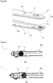
- the propeller (7) is formed by joining an upper fin (17) and a lower fin (18). Two recesses, one disposed on each of the upper fin (17) and the lower fin (18), that extend along the upper fin (17) and the lower fin (18), form the channel (10) that enables the hot air to move along the propeller (7) when the upper fin (17) and the lower fin (18) are joined.
- the upper fin (17) and the lower fin (18) are symmetrically produced and thus ease of production is provided.
- the oven (1) comprises at least one upper outlet hole (105) arranged on the upper fin (17) and at least one lower outlet hole (205) arranged on the lower fin (18).
- the hot air leaving the propeller (7) is enabled to be directed both in the upper and lower directions. Accordingly, the hot air is enabled to be dispersed inside the cooking chamber (2) effectively.
- the air that is heated by the heater (4) is dispersed homogeneously inside the cooking chamber (2) by means of a propeller (7), the rotation speed of which is controlled by controlling the amount of air leaving an air guiding hole (6) disposed thereon.
- the foodstuff placed in the cooking chamber (2) is cooked homogeneously and the cooking performance of the oven (1) is improved.
Landscapes
- Engineering & Computer Science (AREA)
- Chemical & Material Sciences (AREA)
- Combustion & Propulsion (AREA)
- Mechanical Engineering (AREA)
- General Engineering & Computer Science (AREA)
- Baking, Grill, Roasting (AREA)
Abstract
Description
- The present invention relates to an oven wherein the hot air circulation in the cooking chamber is improved.
- In ovens, the cooking process is generally performed by operating together the heaters and the fan disposed in the cooking chamber. The hot air heated by the heaters disposed on the ceiling, the base or the rear wall of the cooking chamber is distributed into the cooking chamber by means of the fan. As the speed of the fan increases, the cooking duration decreases. However, the increase of fan speed results in the burning of the food close to the area where the fan is located and the disruption of the homogeneous heat distribution in the oven.
- In order to provide homogeneous heat distribution inside the oven, air is enabled to be delivered into the cooking chamber at high speeds through a plurality of holes disposed on the ceiling or the base of the cooking chamber. However, in these embodiments, providing the delivery of air at the desired speed through the plurality of holes increases the fan dimensions. This situation causes increase in costs and in the dimensions of the oven.
- In the state of the art International Patent Application No.
WO9734490 - The aim of the present invention is the realization of an oven wherein homogeneous heat distribution is provided.
- The oven realized in order to attain the aim of the present invention, explicated in the first claim and the respective claims thereof, comprises a cooking chamber wherein the foods to be cooked are placed, a casing in form of a box with open front surrounding the cooking chamber, and a heater disposed on the ceiling or the base of the casing. The foodstuff desired to be cooked is placed into the cooking chamber from the open front side. The foodstuff is cooked by heating the cooking chamber by means of the heater.
- The oven of the present invention comprises a propeller that is connected to the casing so as to remain inside the cooking chamber and that has at least one outlet hole enabling the hot air delivered therein to be distributed in the cooking chamber and at least one air guiding hole enabling the propeller to be rotated. The propeller that extends into the cooking chamber without contacting the casing enables the hot air to be distributed into the entire cooking chamber. By means of an extension situated on the air guiding hole, the hot air passing through the air guiding hole is enabled to move in the direction of the rotational axis of the propeller and to create the pushing force that rotates the propeller. The hot air impacts the extension while leaving the air guiding hole and forces the propeller to rotate.
- In an embodiment of the present invention, the oven comprises an air channel that is disposed on the casing and that provides the delivery of air from the cooking chamber to the propeller, and a fan disposed inside the air channel. The air inside the cooking chamber is passed over the heater by the fan and is sucked into the air channel. The hot air is delivered to the propeller from the air channel and is sent back into the cooking chamber through at least one outlet hole arranged on the propeller.
- In another embodiment of the present invention, the oven comprises a channel that is arranged in the propeller and that enables the hot air entering the propeller from the air channel to be conveyed to the outlet hole and the air guiding hole. The air channel having preferably a narrowing configuration enables the hot air entering the air channel to move by accelerating towards the propeller outlet. Thus, hot air with a high flow rate is enabled to be delivered to the cooking chamber.
- In another embodiment of the present invention, the propeller comprises a control member that is disposed inside the channel and that enables the amount of air flowing to the air guiding hole to be controlled. The control member narrows the air passage area in the channel, thus enabling the amount of air flowing to the air guiding hole to be increased or decreased.
- In another embodiment of the present invention, the control member comprises a ball that is disposed inside the channel and that enables the amount of air flowing to the air guiding hole to be controlled. During the rotation of the propeller, the ball moves inside the channel by the effect of the centrifugal force. When the propeller accelerates, the ball moves towards the end of the propeller and narrows the cross-sectional area of the channel, thereby enabling the amount of air delivered to the air guiding hole to be decreased. Thus, the rotational speed of the propeller is decreased by decreasing the amount air passing through the air guiding hole.
- In another embodiment of the present invention, the control member comprises a ball housing that is disposed inside the channel and wherein the ball moves. During the rotation of the propeller, the ball moves between two ends of the ball housing. Upon reaching one end of the ball housing, the ball at least partially closes the channel and at the other end moves away from the air guiding hole, thereby enabling the amount of air delivered to the air guiding hole to be increased.
- In another embodiment of the present invention, the control member comprises a prestress means disposed at the end of the channel. The prestress means, which is preferably a spring, is compressed between the ball and the propeller wall during the movement of the ball towards the end of the propeller with the effect of the centrifugal force. When the rotational speed of the propeller decreases, the centrifugal force exerting on the ball also decreases, the energy stored in the prestress means by compression is transferred to the ball and the ball is enabled to move away from the air guiding hole.
- In another embodiment of the present invention, the oven comprises a fan motor disposed on the air channel. The fan motor is disposed on the air channel so as to remain outside the air channel. The fan motor is positioned so as to be aligned with the fan inside the air channel, thus the fan is enabled to be triggered by the fan motor shaft extending from the fan motor.
- In another embodiment of the present invention, the air channel is formed by joining an upper body and a lower body. When the upper body and the lower body are joined, a gap is formed that is suitable for placing the fan therebetween. Before the upper body and the lower body are joined, the fan is disposed on the lower body so as to be situated in the said gap.
- In another embodiment of the present invention, the propeller is formed by joining an upper fin and a lower fin. A recess is situated on each of the upper fin and the lower fin, positioned so as to be opposite one another when the upper fin and the lower fin are joined. Thus, when the upper body and the lower body are joined, the opposite recesses form the channel.
- In another embodiment of the present invention, the oven comprises at least one upper outlet hole arranged on the upper fin and at least one lower outlet hole arranged on the lower fin. The hot air leaving the propeller is enabled to be distributed to the entire cooking chamber by means of the upper outlet hole and the lower outlet hole. The number and positioning of the upper outlet holes and the lower outlet holes situated on the upper fin and the lower fin are determined by the producer depending on the type of oven used.
- By means of the present invention, an oven is realized wherein the hot air is distributed homogeneously inside the cooking chamber with a higher flow rate by means of a propeller disposed in the cooking chamber, the rotational speed of which is controlled mechanically.
- The oven realized in order to attain the aim of the present invention is illustrated in the attached figures, where:
-
Figure 1 - is the perspective view of an oven. -
Figure 2 - is the perspective view of the cooking chamber and the casing in an embodiment of the present invention. -
Figure 3 - is the rear perspective view of the oven in an embodiment of the present invention. -
Figure 4 - is the front view of the cooking chamber in an embodiment of the present invention. -
Figure 5 - is the perspective view of the air channel in an embodiment of the present invention. -
Figure 6 - is the perspective view of the propeller in an embodiment of the present invention. -
Figure 7 - is the perspective view of the propeller in an embodiment of the present invention. - The elements in the figures are numbered as follows:
- 1. Oven
- 2. Cooking chamber
- 3. Casing
- 4. Heater
- 5. Outlet hole
- 6. Air guiding hole
- 7. Propeller
- 8. Air channel
- 9. Fan
- 10. Channel
- 11. Ball
- 12. Ball housing
- 13. Prestress means
- 14. Fan motor
- 15. Upper body
- 16. Lower body
- 17. Upper fin
- 18. Lower fin
- 19. Control member
- The oven (1) comprises a cooking chamber (2) wherein the foodstuffs to be cooked are placed, a casing (3) in form of a box with open front surrounding the cooking chamber (2) and a heater (4) disposed on the casing (3) (
Figure 1 andFigure 2 ). - The oven (1) of the present invention comprises a propeller (7),
- that is connected to the casing (3) so as to remain inside the cooking chamber (2),
- that has at least one outlet hole (5) enabling the hot air delivered therein to be distributed in the cooking chamber (2) and at least one air guiding hole (6) enabling the propeller (7) to be rotated.
- The hot air is carried back into the cooking chamber (2) by means of the outlet hole (5) situated on the propeller (7). More than one outlet hole (7) is arranged on the propeller (7) preferably positioned on the ceiling of the casing (3). Thus, the hot air is enabled to be distributed homogeneously inside the cooking chamber (2) by means of the outlet holes (5). While leaving the propeller (7) by passing through the air guiding hole (6) located on the propeller (7), the hot air moves in the opposite direction of the propeller (7) rotational direction and exerts pushing force on the propeller (7). Thus, the propeller (7) is enabled to be rotated. As the propeller (7) is rotated, the hot air leaving through the outlet hole (5) is enabled to be distributed effectively inside the cooking chamber (2).
- In an embodiment of the present invention, the oven (1) comprises an air channel (8) that is disposed on the casing (3) and that provides the delivery of the air from the cooking chamber (2) to the propeller (7), and a fan (9) disposed inside the air channel (8). The air that heats up by passing over the heater (4) is taken into the air channel (8) by means of the fan (9) and carried to the propeller (7) via the air channel (8).
- In another embodiment of the present invention, the oven (1) comprises a channel (10) that is situated in the propeller (7) and that enables the hot air entering the propeller (7) from the air channel (10) to be carried to the outlet hole (5) and to the air guiding hole (6). The propeller (7) starts to rotate as the hot air sent from the channel (10) to the air guiding hole (6) exits from the air guiding hole (6). Thus, the hot air delivered from the outlet hole (5) to the cooking chamber (2) is enabled to be dispersed to the entire cooking chamber (2).
- In another embodiment of the present invention, the propeller (7) comprises a control member (19) that is disposed inside the channel (10) and that enables the amount of air flowing to the air guiding hole (6) to be controlled. Thus, the amount of air delivered into the cooking chamber (2) is adjusted.
- In another embodiment of the present invention, the control member (19) comprises a ball (11) that is disposed inside the channel (10) and that enables the amount of air flowing to the air guiding hole (6) to be controlled. During the rotation of the propeller (7), the ball (11) moves towards the end of the propeller (7) by the effect of the centrifugal force, thus closing the channel (10) at least partially. Thus, the amount of air delivered to the air guiding hole (6) is decreased and the rotational speed of the propeller (7) is controlled by limiting the same.
- In another embodiment of the present invention, the control member (19) comprises a ball housing (12) that is disposed inside the channel (10) and wherein the ball (11) moves. The movement of the ball (11) inside the channel (10) is limited by the bell housing (12). In this embodiment, the ball (11) is prevented from entirely closing the channel (10) and interrupting the delivery of air to the air guiding hole (6). Thus, the amount of hot air delivered to the air guiding hole (6) is controlled by the forwards/backwards movement of the ball (11) in the ball housing (12).
- In another embodiment of the present invention, the control member (19) comprises a prestress means (13) disposed at the end of the channel (10). The prestress means (13) exerts a force on the ball (11) during the movement of the ball (11) towards the end of the propeller (7) by the centrifugal force. The ball (11) is pushed towards the end of the propeller (7) by the centrifugal force that increases depending on the increase in the rotational speed of the propeller (7). With the movement of the ball (11), the prestress means (13) is compressed between the ball (11) and the wall of the propeller (7). When the rotational speed of the propeller (7) decreases, the prestress means (13) pushes the ball (11) and enables the ball (11) to move away from the air guiding hole (6).
- In another embodiment of the present invention, the oven (1) comprises a fan motor (14) disposed on the air channel (8). The fan motor (14) is seated on the upper part of the air channel (8). The fan (9) is rotated by means of the fan motor (14) shaft that is connected from the fan motor (14) to the fan (9) by being inserted through a hole arranged on the air channel (8). The hot air can be delivered at high speeds from the air channel (8) to the propeller (7) by means of the fan (9). Thus, the propeller (7) is enabled to be rotated at high speeds and the hot air is enabled to be dispersed homogeneously inside the cooking chamber (2) and also the hot air leaving the propeller (7) is enabled to be delivered over the foodstuff inside the cooking chamber (2) at high speeds, thereby cooking the foodstuff faster.
- In another embodiment of the present invention, the air channel (8) is formed by joining an upper body (15) and a lower body (16). In this embodiment, the upper body (15) and the lower body (16) are joined after the fan (9) is placed on the lower body (16). Thus, ease of assembly is provided.
- In another embodiment of the present invention, the propeller (7) is formed by joining an upper fin (17) and a lower fin (18). Two recesses, one disposed on each of the upper fin (17) and the lower fin (18), that extend along the upper fin (17) and the lower fin (18), form the channel (10) that enables the hot air to move along the propeller (7) when the upper fin (17) and the lower fin (18) are joined. The upper fin (17) and the lower fin (18) are symmetrically produced and thus ease of production is provided.
- In another embodiment of the present invention, the oven (1) comprises at least one upper outlet hole (105) arranged on the upper fin (17) and at least one lower outlet hole (205) arranged on the lower fin (18). By means of the upper outlet hole (105) and the lower outlet hole (205), the hot air leaving the propeller (7) is enabled to be directed both in the upper and lower directions. Accordingly, the hot air is enabled to be dispersed inside the cooking chamber (2) effectively.
- In the oven (1) of the present invention, the air that is heated by the heater (4) is dispersed homogeneously inside the cooking chamber (2) by means of a propeller (7), the rotation speed of which is controlled by controlling the amount of air leaving an air guiding hole (6) disposed thereon. Thus, the foodstuff placed in the cooking chamber (2) is cooked homogeneously and the cooking performance of the oven (1) is improved.
Claims (11)
- An oven (1) comprising a cooking chamber (2) wherein the foodstuffs to be cooked are placed, a casing (3) in form of a box with open front, surrounding the cooking chamber (2), and a heater (4) disposed on the casing (3), characterized by a propeller (7)- that is connected to the casing (3) so as to remain inside the cooking chamber (2),- that has at least one outlet hole (5) enabling the hot air delivered therein to be distributed in the cooking chamber (2) and at least one air guiding hole (6) enabling the propeller (7) to be rotated by enabling the hot air to be moved in the radial direction.
- An oven (1) as in Claim 1, characterized by an air channel (8) that is disposed on the casing (3) and that provides the delivery of the air from the cooking chamber (2) to the propeller (7), and a fan (9) disposed inside the air channel (8).
- An oven (1) as in Claim 1 or 2, characterized by a channel (10) that is situated inside the propeller (7) and that enables the hot air entering the propeller (7) from the air channel (8) to be carried to the outlet hole (5) and the air guiding hole (6).
- An oven (1) as in Claim 3, characterized by a control member (19) that is disposed inside the channel (10) and that enables the amount of air flowing to the air guiding hole (6) to be controlled.
- An oven (1) as in Claim 4, characterized by a ball (11) that is disposed inside the channel (10) and that enables the amount of air flowing to the air guiding hole (6) to be controlled.
- An oven (1) as in Claim 5, characterized by the control member (19) comprising a ball housing (12) that is disposed inside the channel (10) and wherein the ball (11) moves.
- An oven (1) as in Claim 6, characterized by the control member (19) comprising a prestress means (13) disposed at the end of the channel (10).
- An oven (1) as in any one of the above claims, characterized by the fan motor (14) that is disposed on the air channel (8).
- An oven (1) as in any one of the above claims, characterized by the air channel (8) that is formed by joining an upper body (15) and a lower body (16).
- An oven (1) as in any one of the above claims, characterized by the propeller (7) that is formed by joining an upper fin (17) and a lower fin (18).
- An oven (1) as in Claim 10, characterized by at least one upper outlet hole (105) arranged on the upper fin (17) and at least one lower outlet hole (205) arranged on the lower fin (18).
Applications Claiming Priority (1)
| Application Number | Priority Date | Filing Date | Title |
|---|---|---|---|
| TR201513651 | 2015-11-03 |
Publications (1)
| Publication Number | Publication Date |
|---|---|
| EP3165829A1 true EP3165829A1 (en) | 2017-05-10 |
Family
ID=57211425
Family Applications (1)
| Application Number | Title | Priority Date | Filing Date |
|---|---|---|---|
| EP16196572.8A Withdrawn EP3165829A1 (en) | 2015-11-03 | 2016-10-31 | An oven with improved hot air circulation |
Country Status (1)
| Country | Link |
|---|---|
| EP (1) | EP3165829A1 (en) |
Citations (3)
| Publication number | Priority date | Publication date | Assignee | Title |
|---|---|---|---|---|
| WO1997034490A1 (en) | 1996-03-18 | 1997-09-25 | Aktiebolaget Electrolux | A heater unit for ovens |
| US5676044A (en) * | 1996-01-03 | 1997-10-14 | Lara, Jr.; George A. | Rotary air impingement oven |
| WO2015101399A1 (en) * | 2013-12-30 | 2015-07-09 | Arcelik Anonim Sirketi | Cooking oven with improved hot air circulation |
-
2016
- 2016-10-31 EP EP16196572.8A patent/EP3165829A1/en not_active Withdrawn
Patent Citations (3)
| Publication number | Priority date | Publication date | Assignee | Title |
|---|---|---|---|---|
| US5676044A (en) * | 1996-01-03 | 1997-10-14 | Lara, Jr.; George A. | Rotary air impingement oven |
| WO1997034490A1 (en) | 1996-03-18 | 1997-09-25 | Aktiebolaget Electrolux | A heater unit for ovens |
| WO2015101399A1 (en) * | 2013-12-30 | 2015-07-09 | Arcelik Anonim Sirketi | Cooking oven with improved hot air circulation |
Similar Documents
| Publication | Publication Date | Title |
|---|---|---|
| CN107550250B (en) | Steaming and baking integrated device | |
| US8113190B2 (en) | Compact conveyor oven | |
| CN102165266B (en) | Apparatus for preparing food and air guide member therefor | |
| US10451290B2 (en) | Forced convection steam assembly | |
| EP2764295B1 (en) | An oven with increased cooking efficiency | |
| CN1596666B (en) | Convection oven and related air flow system | |
| KR20160093858A (en) | Convection oven | |
| US10371391B2 (en) | Cooking oven provided for heat transfer by convection | |
| US7296510B2 (en) | Cooking device | |
| CN208551408U (en) | A kind of heating kettle that heating efficiency can be improved | |
| JP6898140B2 (en) | Cooker | |
| WO2015101399A1 (en) | Cooking oven with improved hot air circulation | |
| EP3165829A1 (en) | An oven with improved hot air circulation | |
| EP3165830A1 (en) | An oven with improved hot air circulation | |
| JP3939232B2 (en) | Cooker | |
| EP3348914B1 (en) | Oven for cooking foods | |
| CN209285138U (en) | A kind of air channel structure of air fryer | |
| KR100676135B1 (en) | Oven equipped with double convection-fans | |
| EP3253216B1 (en) | Cooking apparatus | |
| EP3128182B1 (en) | Fan for ovens for cooking foods | |
| CN106214011A (en) | Cooking appliance | |
| CN112704407B (en) | Hot air baffle structure for cooking device and oven | |
| CN108167883A (en) | Heating appliance for cooking | |
| CN113749529A (en) | Air oven with heated air circulation heating system | |
| KR100635662B1 (en) | Guide for convection oven |
Legal Events
| Date | Code | Title | Description |
|---|---|---|---|
| PUAI | Public reference made under article 153(3) epc to a published international application that has entered the european phase |
Free format text: ORIGINAL CODE: 0009012 |
|
| AK | Designated contracting states |
Kind code of ref document: A1 Designated state(s): AL AT BE BG CH CY CZ DE DK EE ES FI FR GB GR HR HU IE IS IT LI LT LU LV MC MK MT NL NO PL PT RO RS SE SI SK SM TR |
|
| AX | Request for extension of the european patent |
Extension state: BA ME |
|
| 17P | Request for examination filed |
Effective date: 20171101 |
|
| RBV | Designated contracting states (corrected) |
Designated state(s): AL AT BE BG CH CY CZ DE DK EE ES FI FR GB GR HR HU IE IS IT LI LT LU LV MC MK MT NL NO PL PT RO RS SE SI SK SM TR |
|
| 17Q | First examination report despatched |
Effective date: 20180306 |
|
| GRAP | Despatch of communication of intention to grant a patent |
Free format text: ORIGINAL CODE: EPIDOSNIGR1 |
|
| INTG | Intention to grant announced |
Effective date: 20181221 |
|
| RAP1 | Party data changed (applicant data changed or rights of an application transferred) |
Owner name: ARCELIK ANONIM SIRKETI |
|
| STAA | Information on the status of an ep patent application or granted ep patent |
Free format text: STATUS: THE APPLICATION IS DEEMED TO BE WITHDRAWN |
|
| 18D | Application deemed to be withdrawn |
Effective date: 20190501 |