EP3165385A1 - Device for the towing vehicle-trailer connection - Google Patents
Device for the towing vehicle-trailer connection Download PDFInfo
- Publication number
- EP3165385A1 EP3165385A1 EP16197170.0A EP16197170A EP3165385A1 EP 3165385 A1 EP3165385 A1 EP 3165385A1 EP 16197170 A EP16197170 A EP 16197170A EP 3165385 A1 EP3165385 A1 EP 3165385A1
- Authority
- EP
- European Patent Office
- Prior art keywords
- tubular element
- unlocking
- outer tubular
- female coupling
- configuration
- Prior art date
- Legal status (The legal status is an assumption and is not a legal conclusion. Google has not performed a legal analysis and makes no representation as to the accuracy of the status listed.)
- Granted
Links
- 230000008878 coupling Effects 0.000 claims abstract description 119
- 238000010168 coupling process Methods 0.000 claims abstract description 119
- 238000005859 coupling reaction Methods 0.000 claims abstract description 119
- 238000003780 insertion Methods 0.000 claims abstract description 14
- 230000037431 insertion Effects 0.000 claims abstract description 14
- 238000006073 displacement reaction Methods 0.000 claims description 8
- 230000003993 interaction Effects 0.000 claims description 3
- 230000000694 effects Effects 0.000 description 3
- 239000012530 fluid Substances 0.000 description 1
- 230000000717 retained effect Effects 0.000 description 1
Images


Classifications
-
- B—PERFORMING OPERATIONS; TRANSPORTING
- B60—VEHICLES IN GENERAL
- B60D—VEHICLE CONNECTIONS
- B60D1/00—Traction couplings; Hitches; Draw-gear; Towing devices
- B60D1/58—Auxiliary devices
- B60D1/62—Auxiliary devices involving supply lines, electric circuits, or the like
- B60D1/64—Couplings or joints therefor
-
- B—PERFORMING OPERATIONS; TRANSPORTING
- B60—VEHICLES IN GENERAL
- B60T—VEHICLE BRAKE CONTROL SYSTEMS OR PARTS THEREOF; BRAKE CONTROL SYSTEMS OR PARTS THEREOF, IN GENERAL; ARRANGEMENT OF BRAKING ELEMENTS ON VEHICLES IN GENERAL; PORTABLE DEVICES FOR PREVENTING UNWANTED MOVEMENT OF VEHICLES; VEHICLE MODIFICATIONS TO FACILITATE COOLING OF BRAKES
- B60T17/00—Component parts, details, or accessories of power brake systems not covered by groups B60T8/00, B60T13/00 or B60T15/00, or presenting other characteristic features
- B60T17/04—Arrangements of piping, valves in the piping, e.g. cut-off valves, couplings or air hoses
- B60T17/043—Brake line couplings, air hoses and stopcocks
-
- B—PERFORMING OPERATIONS; TRANSPORTING
- B60—VEHICLES IN GENERAL
- B60T—VEHICLE BRAKE CONTROL SYSTEMS OR PARTS THEREOF; BRAKE CONTROL SYSTEMS OR PARTS THEREOF, IN GENERAL; ARRANGEMENT OF BRAKING ELEMENTS ON VEHICLES IN GENERAL; PORTABLE DEVICES FOR PREVENTING UNWANTED MOVEMENT OF VEHICLES; VEHICLE MODIFICATIONS TO FACILITATE COOLING OF BRAKES
- B60T7/00—Brake-action initiating means
- B60T7/12—Brake-action initiating means for automatic initiation; for initiation not subject to will of driver or passenger
- B60T7/20—Brake-action initiating means for automatic initiation; for initiation not subject to will of driver or passenger specially for trailers, e.g. in case of uncoupling of or overrunning by trailer
-
- F—MECHANICAL ENGINEERING; LIGHTING; HEATING; WEAPONS; BLASTING
- F16—ENGINEERING ELEMENTS AND UNITS; GENERAL MEASURES FOR PRODUCING AND MAINTAINING EFFECTIVE FUNCTIONING OF MACHINES OR INSTALLATIONS; THERMAL INSULATION IN GENERAL
- F16L—PIPES; JOINTS OR FITTINGS FOR PIPES; SUPPORTS FOR PIPES, CABLES OR PROTECTIVE TUBING; MEANS FOR THERMAL INSULATION IN GENERAL
- F16L2201/00—Special arrangements for pipe couplings
- F16L2201/20—Safety or protective couplings
-
- F—MECHANICAL ENGINEERING; LIGHTING; HEATING; WEAPONS; BLASTING
- F16—ENGINEERING ELEMENTS AND UNITS; GENERAL MEASURES FOR PRODUCING AND MAINTAINING EFFECTIVE FUNCTIONING OF MACHINES OR INSTALLATIONS; THERMAL INSULATION IN GENERAL
- F16L—PIPES; JOINTS OR FITTINGS FOR PIPES; SUPPORTS FOR PIPES, CABLES OR PROTECTIVE TUBING; MEANS FOR THERMAL INSULATION IN GENERAL
- F16L37/00—Couplings of the quick-acting type
- F16L37/28—Couplings of the quick-acting type with fluid cut-off means
- F16L37/30—Couplings of the quick-acting type with fluid cut-off means with fluid cut-off means in each of two pipe-end fittings
- F16L37/32—Couplings of the quick-acting type with fluid cut-off means with fluid cut-off means in each of two pipe-end fittings at least one of two lift valves being opened automatically when the coupling is applied
- F16L37/34—Couplings of the quick-acting type with fluid cut-off means with fluid cut-off means in each of two pipe-end fittings at least one of two lift valves being opened automatically when the coupling is applied at least one of the lift valves being of the sleeve type, i.e. a sleeve is telescoped over an inner cylindrical wall
-
- F—MECHANICAL ENGINEERING; LIGHTING; HEATING; WEAPONS; BLASTING
- F16—ENGINEERING ELEMENTS AND UNITS; GENERAL MEASURES FOR PRODUCING AND MAINTAINING EFFECTIVE FUNCTIONING OF MACHINES OR INSTALLATIONS; THERMAL INSULATION IN GENERAL
- F16L—PIPES; JOINTS OR FITTINGS FOR PIPES; SUPPORTS FOR PIPES, CABLES OR PROTECTIVE TUBING; MEANS FOR THERMAL INSULATION IN GENERAL
- F16L37/00—Couplings of the quick-acting type
- F16L37/28—Couplings of the quick-acting type with fluid cut-off means
- F16L37/30—Couplings of the quick-acting type with fluid cut-off means with fluid cut-off means in each of two pipe-end fittings
- F16L37/32—Couplings of the quick-acting type with fluid cut-off means with fluid cut-off means in each of two pipe-end fittings at least one of two lift valves being opened automatically when the coupling is applied
- F16L37/35—Couplings of the quick-acting type with fluid cut-off means with fluid cut-off means in each of two pipe-end fittings at least one of two lift valves being opened automatically when the coupling is applied at least one of the valves having an axial bore
-
- F—MECHANICAL ENGINEERING; LIGHTING; HEATING; WEAPONS; BLASTING
- F16—ENGINEERING ELEMENTS AND UNITS; GENERAL MEASURES FOR PRODUCING AND MAINTAINING EFFECTIVE FUNCTIONING OF MACHINES OR INSTALLATIONS; THERMAL INSULATION IN GENERAL
- F16L—PIPES; JOINTS OR FITTINGS FOR PIPES; SUPPORTS FOR PIPES, CABLES OR PROTECTIVE TUBING; MEANS FOR THERMAL INSULATION IN GENERAL
- F16L37/00—Couplings of the quick-acting type
- F16L37/56—Couplings of the quick-acting type for double-walled or multi-channel pipes or pipe assemblies
Definitions
- the present invention relates to a connection device for trailers of agricultural machines.
- the towing vehicles are connected to the relative trailer by means of a connection device that allows placing the corresponding braking systems in communication to one another, in such a way that the braking of the towing vehicle operated by the operator also causes the braking of the towed trailer.
- the braking system of the trailer is therefore driven by the braking system of the tractor in order to synchronize the braking forces acting on the same.
- connection device between the towing vehicle and the relative trailer must comprise a portion connectable to the trailer and having a pair of female couplings intended to receive the corresponding male couplings connectable to the towing vehicle.
- the main aim of the present invention is to provide a connection device applicable to the trailer which allows the sequential engagement and disengagement of the female couplings from the relative male couplings.
- one object of the present invention is to ensure the sequential disengagement of the male couplings associated with the towing vehicle from the relative female couplings even under emergency conditions, or in the case of braking of the towing hook of the trailer.
- Another object of the present invention is to provide a connection device for trailers of agricultural machines which allows to overcome the mentioned drawbacks of the prior art within the ambit of a simple, rational, easy, effective to use and affordable solution.
- the device 1 comprises a base body 2 associable with a trailer, at least a first female coupling 3, communicating with a control line 32 connectable to the braking system of the trailer, and at least a second female coupling 4, communicating with at least one additional line 29 which acts on the parking brake of the trailer, and with at least one by-pass line 30 communicating with a discharge tank.
- the first and the second female couplings 3, 4 are intended to receive a first and a second male coupling 5, 6 respectively, associable with a towing vehicle and connectable to the relative braking system.
- first and second male couplings 5, 6 are connectable to corresponding valves adapted to send to the same a work fluid at a first and at a second pressure, respectively.
- Valve means 31 are also provided adapted to place in communication and isolate the additional line 29 and the by-pass line 30 following the exit and the insertion respectively, of the male coupling 6 inside the relative female coupling 4.
- the first female coupling 3 comprises a first outer tubular element 3a and a first inner tubular element 3b, inserted one inside the other and mutually movable between them, and first locking means 3c associated with the first inner tubular element 3b and adapted to allow the locking and unlocking of the first male coupling 5 from the first female coupling itself.
- the first inner tubular element 3b and the first outer tubular element 3a are mutually movable between an unlocking configuration, in which the first locking means 3c allow the insertion/removal of the first male coupling 5, and a locking configuration, in which the first locking means 3c prevent the relative movement between the first male coupling 5 and the first female coupling 3.
- the first locking means 3c are of the type of a plurality of balls; the first inner tubular element 3b has a plurality of seats 7 inside which the balls 3c are housed and the first outer tubular element 3a defines a first retaining surface 8 against which the spheres rest in the locking configuration and has a first recess 9, which allows the balls 3c to move to the unlocking configuration.
- the first male coupling 5 in turn has a first annular groove 10 inside which the balls 3c are inserted.
- the balls 3c are inserted inside the first groove 10 and the extremity of the first male coupling itself contacts an abutment surface 11 defined inside the first inner tubular element 3b, by moving the latter with respect to the first outer tubular element 3a until the achievement of the locking configuration.
- the second female coupling 4 comprises a second outer tubular element 4a and a second inner tubular element 4b, arranged one inside the other, and second locking means 4c associated with the second inner tubular element 4b.
- the second outer tubular element 4a and the second inner tubular element 4b are mutually movable between an unlocking configuration, in which the second locking means 4c allow for the insertion/removal of the second male coupling 6, and a locking configuration, in which the second locking means 4c prevent the relative movement between the second male coupling 6 and the second female coupling 4.
- the second locking means 4c are of the type of a plurality of balls housed inside corresponding seats 12 defined in the second inner tubular element 4b and, in the relative unlocking configuration, they are inserted inside a second recess 13 defined on the second outer tubular element 4a, while in the locking configuration they rest against a second retaining surface 14 defined by the second outer tubular element itself.
- the second male coupling 6 has in turn a second annular groove 15 inside which the balls 4c are inserted.
- the balls 3c are inserted inside the first groove 10 and the extremity of the first male coupling itself contacts an abutment surface 11 defined inside the first inner tubular element 3b, by moving the latter with respect to the first outer tubular element 3a until the achievement of the locking configuration.
- the second inner tubular element 4b is fixed with respect to the body 2 and the second outer tubular element 4a is movable with respect to the inner one between the aforementioned unlocking and locking configurations.
- the device 1 also comprises an unlocking element 28 locked together with the second outer tubular element 4a and movable between a passive position and an active position, in which the second outer tubular element 4a is located in the locking configuration and in the unlocking configuration, respectively.
- the unlocking element 28 is thus movable with respect to the body 2 in its displacement between the passive position and the active position.
- elastic means 16 are provided adapted to press the second outer tubular element 4a towards the relative locking configuration.
- the balls 4c are inserted in turn inside the second groove 15 thus releasing the second outer tubular element 4a that, by effect of the action of the elastic means 16, moves to the locking configuration.
- the unlocking element 28 defines a locator surface 17 contactable by a user to manually move it from the locking to the unlocking configuration.
- the device 1 also comprises emergency means 18 operable to move the unlocking element 28 from the passive position to the active position following the application of a force of predefined entity on the emergency means themselves.
- the emergency means 18 comprise at least an actuation element 19 mechanically connected to the unlocking element 28 and movable with respect to the body 2 between a rest position, in which the unlocking element 28 is movable between the active and the passive position, and an emergency position, in which it is displaced with respect to the rest position and drags the unlocking element 28 towards the active position.
- the actuation element 19 is connected to a flexible pull element 20, the type of an inextensible cable or a rope, connectable on the opposite side to the trailer.
- the pull element 20 is adapted to move the actuation element 19 with respect to the body 2 following the achievement of the aforementioned predefined force.
- the pull element 20 is tensioned by exerting a force on the actuation element 19.
- the pull element 20 has lower extension than the pipes that connect the trailer to the towing vehicle, in such a way as to avoid breakage or damage of the same.
- the first female coupling 3 is slidably movable with respect to the body 2 between a normal operating position, in which it is substantially aligned with the second female coupling 4 and an engagement/disengagement position, in which it protrudes with respect to the second female coupling 4 to allow for the sequential insertion and removal of the male couplings 5 and 6 with respect to the relative female couplings 3 and 4.
- the engagement/disengagement position the first female coupling 3 is moved away from the body 2 with respect to the normal operating position.
- both the first outer tubular element 3a and the first inner tubular element 3b are slidably movable with respect to the body 2 between the normal operating position and the engagement/disengagement position.
- one of the body 2 and the unlocking element 28 is adapted to interact with the first outer tubular element 3a to drag it to the relative unlocking configuration following the achievement of the active position by the unlocking element itself and the subsequent moving of the body 2 away from the male couplings 5, 6.
- the body 2 moves away from the male couplings 5, 6 and, after the unlocking element 28 has achieved the active position (manually or by effect of the emergency means 18), thus allowing for the removal of the second male coupling 6 from the relative female coupling 4, it shifts with respect to the first female coupling 3 (still connected to the first male coupling 5) until it interacts with the first outer tubular element 3a causing the displacement thereof with respect to the first inner tubular element 3b and the achievement of the relative unlocking configuration.
- the first outer tubular element 3a has a first and a second abutment surface, identified with reference numbers 21 and 22 respectively, adapted to rest against relative counter abutments 23 and 24 in the normal operating position and in the engagement/disengagement position, respectively.
- the first inner tubular element 3b moves locked together with the first outer tubular element 3a during its displacement from the normal operating position to the engagement/disengagement position.
- the counter abutments 23 and 24 are defined by one of the unlocking element 28, as in the embodiment of Figures 1 to 6 , and the body 2, as in the embodiment of Figure 7 .
- the counter abutment 24 defined by the unlocking element itself or by the body 2 depending on the embodiment, interacts with the abutment surface 22 by moving this way the first outer tubular element 3a with respect to the first inner tubular element 3b until the achievement of the relative unlocking configuration.
- the first female coupling 3 comprises elastic means 25 adapted to push the first inner tubular element 3b towards the relative locking configuration.
- the first inner tubular element 3b is further movable with respect to the first outer tubular element 3a, counteracting the elastic means 25, to achieve the relative unlocking configuration.
- the device 1 comprises at least one guide element 26 for guiding the sliding of the first female coupling 3 from the normal operating position to the engagement/disengagement position and vice versa.
- the guide element 26 is defined by the unlocking element 28. More particularly, in this second embodiment, the unlocking element 28 has an extension which surrounds the first female coupling 3.
- the guide element 26 is defined by the body 2.
- the body 2 has a through hole 27 through which the first female coupling 3 is slidably inserted.
- the counter abutment surfaces 23 and 24 are therefore defined by the body 2.
- the inner and outer tubular elements 3a, 3b and 4a, 4b are in the corresponding locking configurations and the first female coupling 3 is in the normal operating position.
- the first female coupling 3 is initially brought to the engagement position, or by moving the first tubular elements 3a, 3b until the second abutment surface 22 rests against the second counter abutment surface 24.
- the first female coupling 3 is closer to the first male coupling 5 than the second female coupling 4 to the second male coupling 6. At this point it is possible to further move the first inner tubular element 3b with respect to the first outer tubular element 3a in such a way as to bring it to the relative unlocking configuration.
- the balls 3c are inserted inside the first groove 10 and the first male coupling 5 continues until its axial extremity abuts against the abutment surface 11, returning the first inner tubular element 3b to the locking configuration.
- the balls 3c are retained inside the relative seats 12 formed on the first inner tubular element 3b and inside the first groove 10 by the first retaining surface 8 defined by the first outer tubular element 3a.
- the body 2 is moved so as to return the first female coupling 3 to the normal operating position and, at the same time, to move the second female coupling 4 close to the second male coupling 6.
- the balls 4c are inserted inside the second groove 15 defined on the second male coupling 6 and, at the same time, the second outer tubular element 4a is pushed by the elastic means 16 to the locking configuration.
- the first and the second male coupling 5 and 6 are therefore inserted in sequence inside the relative female couplings 3 and 4.
- the first outer tubular element 3a is brought to the unlocking configuration by effect of the interaction between the second counter abutment surface 24 and the second abutment surface 22, thus allowing to also remove the first male coupling 5.
- connection device to which the present invention refers allows for the sequential engagement and disengagement of the female couplings to the relative male couplings.
- the possibility of moving the female coupling connected to the control line with respect to the body of the device and with respect to the female coupling connected to the additional line allows moving in sequence the female couplings themselves close to the corresponding male couplings.
Abstract
Description
- The present invention relates to a connection device for trailers of agricultural machines.
- As is known, today the towing vehicles are connected to the relative trailer by means of a connection device that allows placing the corresponding braking systems in communication to one another, in such a way that the braking of the towing vehicle operated by the operator also causes the braking of the towed trailer.
- The braking system of the trailer is therefore driven by the braking system of the tractor in order to synchronize the braking forces acting on the same.
- According to the recently introduced regulations the connection device between the towing vehicle and the relative trailer must comprise a portion connectable to the trailer and having a pair of female couplings intended to receive the corresponding male couplings connectable to the towing vehicle.
- Of these female couplings one is connected to the braking system of the trailer and the other to the parking and/or automatic brake of the trailer itself, in such a way that, if the aforementioned male couplings detach from the relative female couplings, and therefore the oil supply lacks in the braking system of the trailer, the relative parking and/or automatic brake comes into operation.
- The main aim of the present invention is to provide a connection device applicable to the trailer which allows the sequential engagement and disengagement of the female couplings from the relative male couplings. Within this aim, one object of the present invention is to ensure the sequential disengagement of the male couplings associated with the towing vehicle from the relative female couplings even under emergency conditions, or in the case of braking of the towing hook of the trailer.
- Another object of the present invention is to provide a connection device for trailers of agricultural machines which allows to overcome the mentioned drawbacks of the prior art within the ambit of a simple, rational, easy, effective to use and affordable solution.
- The aforementioned objects are achieved by the present connection device for the towing vehicle-trailer connection according to claim 1.
- Other characteristics and advantages of the present invention will become better evident from the description of a preferred, but not exclusive, embodiment of a connection device for trailers of agricultural machines, illustrated only by way of an indicative, but non-limiting, example in the accompanying drawings, in which:
-
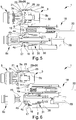
Figures 1 to 3 represent the engagement phases of a device according to the invention, in a first embodiment, to the relative male couplings; -
Figures 4 to 6 represent the disengagement phases of the device according to the invention, in the first embodiment, from the relative male couplings; -
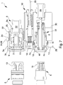
Figure 7 represents a device according to the invention in a second embodiment. With particular reference to such figures, globally indicated with reference number 1 is a connection device for trailers of agricultural machines. - The device 1 comprises a
base body 2 associable with a trailer, at least a firstfemale coupling 3, communicating with acontrol line 32 connectable to the braking system of the trailer, and at least a second female coupling 4, communicating with at least oneadditional line 29 which acts on the parking brake of the trailer, and with at least one by-pass line 30 communicating with a discharge tank. - The first and the second
female couplings 3, 4 are intended to receive a first and asecond male coupling - In particular, the first and
second male couplings - Valve means 31 are also provided adapted to place in communication and isolate the
additional line 29 and the by-pass line 30 following the exit and the insertion respectively, of themale coupling 6 inside the relative female coupling 4. - The first
female coupling 3 comprises a first outertubular element 3a and a first innertubular element 3b, inserted one inside the other and mutually movable between them, and first locking means 3c associated with the first innertubular element 3b and adapted to allow the locking and unlocking of the firstmale coupling 5 from the first female coupling itself. - The first inner
tubular element 3b and the first outertubular element 3a are mutually movable between an unlocking configuration, in which the first locking means 3c allow the insertion/removal of the firstmale coupling 5, and a locking configuration, in which the first locking means 3c prevent the relative movement between the firstmale coupling 5 and the firstfemale coupling 3. Advantageously, the first locking means 3c are of the type of a plurality of balls; the first innertubular element 3b has a plurality ofseats 7 inside which theballs 3c are housed and the first outertubular element 3a defines afirst retaining surface 8 against which the spheres rest in the locking configuration and has afirst recess 9, which allows theballs 3c to move to the unlocking configuration. The firstmale coupling 5 in turn has a firstannular groove 10 inside which theballs 3c are inserted. - More in detail, following the insertion of the first
male coupling 5 inside the firstfemale coupling 3, with the firsttubular elements balls 3c are inserted inside thefirst groove 10 and the extremity of the first male coupling itself contacts anabutment surface 11 defined inside the first innertubular element 3b, by moving the latter with respect to the first outertubular element 3a until the achievement of the locking configuration. - The second female coupling 4 comprises a second outer
tubular element 4a and a second innertubular element 4b, arranged one inside the other, and second locking means 4c associated with the second innertubular element 4b. The second outertubular element 4a and the second innertubular element 4b are mutually movable between an unlocking configuration, in which the second locking means 4c allow for the insertion/removal of the secondmale coupling 6, and a locking configuration, in which the second locking means 4c prevent the relative movement between thesecond male coupling 6 and the second female coupling 4. - Advantageously, the second locking means 4c are of the type of a plurality of balls housed inside
corresponding seats 12 defined in the second innertubular element 4b and, in the relative unlocking configuration, they are inserted inside asecond recess 13 defined on the second outertubular element 4a, while in the locking configuration they rest against a second retainingsurface 14 defined by the second outer tubular element itself. - The
second male coupling 6 has in turn a secondannular groove 15 inside which theballs 4c are inserted. - More in detail, following the insertion of the first
male coupling 5 inside the firstfemale coupling 3, with thetubular elements balls 3c are inserted inside thefirst groove 10 and the extremity of the first male coupling itself contacts anabutment surface 11 defined inside the first innertubular element 3b, by moving the latter with respect to the first outertubular element 3a until the achievement of the locking configuration. - Preferably, the second inner
tubular element 4b is fixed with respect to thebody 2 and the second outertubular element 4a is movable with respect to the inner one between the aforementioned unlocking and locking configurations. - The device 1 also comprises an
unlocking element 28 locked together with the second outertubular element 4a and movable between a passive position and an active position, in which the second outertubular element 4a is located in the locking configuration and in the unlocking configuration, respectively. The unlockingelement 28 is thus movable with respect to thebody 2 in its displacement between the passive position and the active position. Conveniently,elastic means 16 are provided adapted to press the second outertubular element 4a towards the relative locking configuration. - Following the insertion of the
second male coupling 6 inside the second female coupling 4, and more particularly of the second innertubular element 4b, theballs 4c are inserted in turn inside thesecond groove 15 thus releasing the second outertubular element 4a that, by effect of the action of theelastic means 16, moves to the locking configuration. - The unlocking
element 28 defines alocator surface 17 contactable by a user to manually move it from the locking to the unlocking configuration. Advantageously, the device 1 also comprises emergency means 18 operable to move theunlocking element 28 from the passive position to the active position following the application of a force of predefined entity on the emergency means themselves. - More in detail, the emergency means 18 comprise at least an
actuation element 19 mechanically connected to theunlocking element 28 and movable with respect to thebody 2 between a rest position, in which theunlocking element 28 is movable between the active and the passive position, and an emergency position, in which it is displaced with respect to the rest position and drags theunlocking element 28 towards the active position. - The
actuation element 19 is connected to aflexible pull element 20, the type of an inextensible cable or a rope, connectable on the opposite side to the trailer. Thepull element 20 is adapted to move theactuation element 19 with respect to thebody 2 following the achievement of the aforementioned predefined force. For example, in the case of breaking of the towing hook of the trailer, thepull element 20 is tensioned by exerting a force on theactuation element 19. Conveniently, thepull element 20 has lower extension than the pipes that connect the trailer to the towing vehicle, in such a way as to avoid breakage or damage of the same. - According to the invention, the first
female coupling 3 is slidably movable with respect to thebody 2 between a normal operating position, in which it is substantially aligned with the second female coupling 4 and an engagement/disengagement position, in which it protrudes with respect to the second female coupling 4 to allow for the sequential insertion and removal of themale couplings female couplings 3 and 4. In other words, in the engagement/disengagement position the firstfemale coupling 3 is moved away from thebody 2 with respect to the normal operating position. - More in detail, both the first outer
tubular element 3a and the first innertubular element 3b are slidably movable with respect to thebody 2 between the normal operating position and the engagement/disengagement position. - According to the invention, moreover, one of the
body 2 and theunlocking element 28 is adapted to interact with the first outertubular element 3a to drag it to the relative unlocking configuration following the achievement of the active position by the unlocking element itself and the subsequent moving of thebody 2 away from themale couplings body 2 moves away from themale couplings element 28 has achieved the active position (manually or by effect of the emergency means 18), thus allowing for the removal of the secondmale coupling 6 from the relative female coupling 4, it shifts with respect to the first female coupling 3 (still connected to the first male coupling 5) until it interacts with the first outertubular element 3a causing the displacement thereof with respect to the first innertubular element 3b and the achievement of the relative unlocking configuration. - Advantageously, the first outer
tubular element 3a has a first and a second abutment surface, identified withreference numbers relative counter abutments tubular element 3b moves locked together with the first outertubular element 3a during its displacement from the normal operating position to the engagement/disengagement position. - The
counter abutments unlocking element 28, as in the embodiment ofFigures 1 to 6 , and thebody 2, as in the embodiment ofFigure 7 . - More in detail, therefore, following the displacement of the
unlocking element 28 to the active position and the displacement of thebody 2 away from themale couplings counter abutment 24, defined by the unlocking element itself or by thebody 2 depending on the embodiment, interacts with theabutment surface 22 by moving this way the first outertubular element 3a with respect to the first innertubular element 3b until the achievement of the relative unlocking configuration. - Conveniently, the first
female coupling 3 compriseselastic means 25 adapted to push the first innertubular element 3b towards the relative locking configuration. - After achieving the engagement/disengagement position, or when the
second abutment surface 22 rests against the secondcounter abutment surface 24, the first innertubular element 3b is further movable with respect to the first outertubular element 3a, counteracting theelastic means 25, to achieve the relative unlocking configuration. - Advantageously, the device 1 comprises at least one
guide element 26 for guiding the sliding of the firstfemale coupling 3 from the normal operating position to the engagement/disengagement position and vice versa. - In the first embodiment represented in
Figures 1 to 6 , theguide element 26 is defined by theunlocking element 28. More particularly, in this second embodiment, theunlocking element 28 has an extension which surrounds the firstfemale coupling 3. - In the second embodiment shown in
Figure 7 , on the other hand, theguide element 26 is defined by thebody 2. In other words, thebody 2 has a throughhole 27 through which the firstfemale coupling 3 is slidably inserted. In this first embodiment, thecounter abutment surfaces body 2. - The operation of the present invention is as follows.
- Before moving closer to the
male couplings tubular elements female coupling 3 is in the normal operating position. - More particularly, in both
female couplings 3 and 4, the relative locking means 3c, 4c rest against the correspondingretaining surfaces tubular elements - To carry out the engagement with the
male couplings female coupling 3 is initially brought to the engagement position, or by moving the firsttubular elements second abutment surface 22 rests against the secondcounter abutment surface 24. - In this configuration, the first
female coupling 3 is closer to the firstmale coupling 5 than the second female coupling 4 to the secondmale coupling 6. At this point it is possible to further move the first innertubular element 3b with respect to the first outertubular element 3a in such a way as to bring it to the relative unlocking configuration. - After achieving this configuration, it is possible to introduce the first
male coupling 5 inside the firstfemale coupling 3 and, more particularly, in the first innertubular element 3b. - Following this insertion, the
balls 3c are inserted inside thefirst groove 10 and the firstmale coupling 5 continues until its axial extremity abuts against theabutment surface 11, returning the first innertubular element 3b to the locking configuration. In this configuration theballs 3c are retained inside therelative seats 12 formed on the first innertubular element 3b and inside thefirst groove 10 by thefirst retaining surface 8 defined by the first outertubular element 3a. Subsequently thebody 2 is moved so as to return the firstfemale coupling 3 to the normal operating position and, at the same time, to move the second female coupling 4 close to the secondmale coupling 6. - Following this insertion, the
balls 4c are inserted inside thesecond groove 15 defined on the secondmale coupling 6 and, at the same time, the second outertubular element 4a is pushed by the elastic means 16 to the locking configuration. - The first and the second
male coupling female couplings 3 and 4. - The disengagement operation of the
male couplings - More particularly, to remove the
male couplings element 28 to bring it to the active position. - After achieving this position, it is possible to move the
body 2 away from themale couplings male coupling 6 from the relative female coupling 4 and the simultaneous displacement of the firstfemale coupling 3 from the normal operating position to the engagement/disengagement position. - After achieving this position, by moving the
body 2 further away from themale couplings tubular element 3a is brought to the unlocking configuration by effect of the interaction between the secondcounter abutment surface 24 and thesecond abutment surface 22, thus allowing to also remove the firstmale coupling 5. - It has in practice been found that the described invention achieves the intended objects and the fact is particularly underlined that the connection device to which the present invention refers, allows for the sequential engagement and disengagement of the female couplings to the relative male couplings.
- In particular, the possibility of moving the female coupling connected to the control line with respect to the body of the device and with respect to the female coupling connected to the additional line allows moving in sequence the female couplings themselves close to the corresponding male couplings.
Claims (9)
- Device (1) for the towing vehicle-trailer connection, comprising:- a base body (2) associable with a trailer;- at least a first female coupling (3), communicating with a control line (32) connectable to the braking system of the trailer, and at least a second female coupling (4), communicating with at least one additional line (29) which acts on the parking brake of the trailer; said first and second female couplings (3, 4) being intended to receive a first and a second male coupling (5, 6) respectively, which are associable with a towing vehicle and connectable to the corresponding braking system;- wherein said first female coupling (3) comprises a first outer tubular element (3a) and a first inner tubular element (3b) arranged one inside the other and comprises first locking means (3c) associated with said first inner tubular element (3b); said first outer tubular element (3a) and said first inner tubular element (3b) being mutually movable between an unlocking configuration, in which said first locking means (3c) allow for the insertion/removal of the first male coupling (5), and a locking configuration, in which said first locking means (3c) prevent the relative movement between the first male coupling (5) and the first female coupling (3);- wherein said second female coupling (4) comprises a second outer tubular element (4a) and a second inner tubular element (4b) arranged one inside the other and comprises second locking means (4c) associated with said second inner tubular element (4b); said second outer tubular element (4a) and said second inner tubular element (4b) being mutually movable between an unlocking configuration, in which said second locking means (4c) allow for the insertion/removal of the second male coupling (6), and a locking configuration, in which said second locking means (4c) prevent the relative movement between the second male coupling (6) and the second female coupling (4);- at least one unlocking element (28) locked together with said second outer tubular element (4a) and movable between a passive position and an active position in which the second outer tubular element (4a) is located in the locking configuration and in the unlocking configuration respectively,characterized in that said first female coupling (3) is slidably movable with respect to said body (2) between a normal operating position, in which it is substantially aligned with said second female coupling (4) and an engagement/disengagement position, in which it protrudes with respect to said second female coupling (4) to allow for the insertion and sequential removal of said male couplings (5, 6) with respect to the relative female couplings (3, 4), one of said body (2) and said unlocking element (28) being able to interact with said first outer tubular element (3a) to drag it to the relative unlocking configuration following the achievement of the active position by the unlocking element itself and the subsequent moving of said body (2) away from the male couplings (5, 6).
- Device (1) according to claim 1, characterized in that said first outer tubular element (3a) has a first and a second abutment surface (21, 22) able to rest against relative counter abutment surfaces (23, 24) in the normal operating position and in the engagement/disengagement position respectively, said first inner tubular element (3b) moving locked together said first outer tubular element (3a) during its displacement between the normal operating position and the engagement/disengagement position and said first outer tubular element (3a) moving towards the unlocking configuration following the interaction of said second abutment surface (22) with the relative counter abutment surface (24) and of the displacement of said body (2) away from the male couplings (5, 6).
- Device (1) according to claim 2, characterized in that one of said body (2) and said unlocking element (28) is able to drag said first outer tubular element (3a) in the relative unlocking configuration following the interaction between said second abutment surface (22) and the relative counter abutment surface (24), the latter being defined by the body (2) or by the unlocking element themselves.
- Device (1) according to one or more of the preceding claims, characterized in that said second inner tubular element (4b) is fixed with respect to said body (2) and in that said second outer tubular element (4a) is movable from the locking configuration towards the unlocking configuration counteracting the elastic means (16).
- Device (1) according to one or more of the preceding claims, characterized in that it comprises at least one guide element (26) for guiding the sliding of said first female coupling (3) from the normal operating position to the engagement/disengagement position and vice versa.
- Device (1) according to claim 5, characterized in that said guide element (26) is defined by said body (2).
- Device according to claim 5, characterized in that said guide element (26) is defined by said unlocking element (28).
- Device (1) according to one or more of the preceding claims, characterized in that it comprises emergency means (18) operable to move said unlocking element (28) from the passive position to the active position.
- Device (1) according to one or more of the preceding claims, characterized in that said second female coupling (4) comprises at least one by-pass line (30) connectable to a discharge tank and valve means (31) able to place selectively in communication and isolating said additional line (29) and said by-pass line (30) following the exit and the insertion respectively, of the relative male coupling (6).
Applications Claiming Priority (1)
| Application Number | Priority Date | Filing Date | Title |
|---|---|---|---|
| ITUB2015A004950A ITUB20154950A1 (en) | 2015-11-04 | 2015-11-04 | CONNECTION DEVICE FOR AGRICULTURAL MACHINE TRAILERS |
Publications (2)
| Publication Number | Publication Date |
|---|---|
| EP3165385A1 true EP3165385A1 (en) | 2017-05-10 |
| EP3165385B1 EP3165385B1 (en) | 2018-09-05 |
Family
ID=55409998
Family Applications (1)
| Application Number | Title | Priority Date | Filing Date |
|---|---|---|---|
| EP16197170.0A Active EP3165385B1 (en) | 2015-11-04 | 2016-11-03 | Device for the towing vehicle-trailer connection |
Country Status (2)
| Country | Link |
|---|---|
| EP (1) | EP3165385B1 (en) |
| IT (1) | ITUB20154950A1 (en) |
Citations (3)
| Publication number | Priority date | Publication date | Assignee | Title |
|---|---|---|---|---|
| GB717702A (en) * | 1950-12-13 | 1954-11-03 | M B G Corp | Improvements in or relating to a coupling unit for fluid conduits |
| GB2077872A (en) * | 1980-05-13 | 1981-12-23 | White E A White D J | Pipe Coupling |
| WO2015068141A2 (en) * | 2013-11-11 | 2015-05-14 | Stucchi S.P.A. | Fluid transmission coupler with rear chamber fed by oblique pipe |
-
2015
- 2015-11-04 IT ITUB2015A004950A patent/ITUB20154950A1/en unknown
-
2016
- 2016-11-03 EP EP16197170.0A patent/EP3165385B1/en active Active
Patent Citations (3)
| Publication number | Priority date | Publication date | Assignee | Title |
|---|---|---|---|---|
| GB717702A (en) * | 1950-12-13 | 1954-11-03 | M B G Corp | Improvements in or relating to a coupling unit for fluid conduits |
| GB2077872A (en) * | 1980-05-13 | 1981-12-23 | White E A White D J | Pipe Coupling |
| WO2015068141A2 (en) * | 2013-11-11 | 2015-05-14 | Stucchi S.P.A. | Fluid transmission coupler with rear chamber fed by oblique pipe |
Also Published As
| Publication number | Publication date |
|---|---|
| ITUB20154950A1 (en) | 2017-05-04 |
| EP3165385B1 (en) | 2018-09-05 |
Similar Documents
| Publication | Publication Date | Title |
|---|---|---|
| EP0664866B1 (en) | Hose coupling for compressed air | |
| US9897206B2 (en) | Actuator for actuating a parking lock | |
| CN109578733B (en) | Hydraulic and/or pneumatic connector | |
| WO2005081901A3 (en) | Remotely releasable coupler and hose retrieval mechanism for airbrake system | |
| US9821822B2 (en) | Automatic parking brake for truck mounted brake cylinder | |
| CN104044417A (en) | Driving brake traction device for full trailer | |
| EP2962912A2 (en) | Braking device | |
| EP3000631B1 (en) | Device for the towing vehicle-trailer connection | |
| EP3165385B1 (en) | Device for the towing vehicle-trailer connection | |
| EP3294596B1 (en) | Braking device | |
| EP3085590A1 (en) | Device for controlling the braking of a trailer | |
| EP2952398B1 (en) | Valve assembly | |
| EP3368385B1 (en) | Braking device for trailers of agricultural machines | |
| EP3650293B1 (en) | Device for controlling the braking of a trailer | |
| EP2955073B1 (en) | Device for the towing vehicle-trailer connection | |
| EP3515764B1 (en) | A system preventing the activation of a trailer's overrun brakes during reversing | |
| EP3401176B1 (en) | Device for controlling the braking of a trailer | |
| EP3225473B1 (en) | Device for the control of the braking of a trailer | |
| EP3000672B1 (en) | Valve assembly for trailer | |
| EP3319848B1 (en) | Actuating device of a valve for the braking of a trailer | |
| CA2981812C (en) | Automatic parking brake for truck mounted brake cylinder | |
| EP3085589A1 (en) | Valve assembly | |
| EP3401170B1 (en) | Braking device | |
| US20180112731A1 (en) | Actuator Having Controlled Blocking Of An End Position And Method For Operating A Parking Brake Having Such An Actuator | |
| EP1149008A1 (en) | Safety device for and system to improve safety of braking systems of articulated vehicles |
Legal Events
| Date | Code | Title | Description |
|---|---|---|---|
| PUAI | Public reference made under article 153(3) epc to a published international application that has entered the european phase |
Free format text: ORIGINAL CODE: 0009012 |
|
| STAA | Information on the status of an ep patent application or granted ep patent |
Free format text: STATUS: THE APPLICATION HAS BEEN PUBLISHED |
|
| AK | Designated contracting states |
Kind code of ref document: A1 Designated state(s): AL AT BE BG CH CY CZ DE DK EE ES FI FR GB GR HR HU IE IS IT LI LT LU LV MC MK MT NL NO PL PT RO RS SE SI SK SM TR |
|
| AX | Request for extension of the european patent |
Extension state: BA ME |
|
| STAA | Information on the status of an ep patent application or granted ep patent |
Free format text: STATUS: REQUEST FOR EXAMINATION WAS MADE |
|
| 17P | Request for examination filed |
Effective date: 20171108 |
|
| RBV | Designated contracting states (corrected) |
Designated state(s): AL AT BE BG CH CY CZ DE DK EE ES FI FR GB GR HR HU IE IS IT LI LT LU LV MC MK MT NL NO PL PT RO RS SE SI SK SM TR |
|
| GRAP | Despatch of communication of intention to grant a patent |
Free format text: ORIGINAL CODE: EPIDOSNIGR1 |
|
| STAA | Information on the status of an ep patent application or granted ep patent |
Free format text: STATUS: GRANT OF PATENT IS INTENDED |
|
| 111Z | Information provided on other rights and legal means of execution |
Free format text: AL AT BE BG CH CY CZ DE DK EE ES FI FR GB GR HR HU IE IS IT LT LU LV MC MK MT NL NO PL PT RO RS SE SI SK SM TR Effective date: 20180208 |
|
| RAP1 | Party data changed (applicant data changed or rights of an application transferred) |
Owner name: SAFIM S.P.A. |
|
| INTG | Intention to grant announced |
Effective date: 20180326 |
|
| GRAS | Grant fee paid |
Free format text: ORIGINAL CODE: EPIDOSNIGR3 |
|
| GRAA | (expected) grant |
Free format text: ORIGINAL CODE: 0009210 |
|
| STAA | Information on the status of an ep patent application or granted ep patent |
Free format text: STATUS: THE PATENT HAS BEEN GRANTED |
|
| RIN1 | Information on inventor provided before grant (corrected) |
Inventor name: MAMEI, ANDREA Inventor name: MAMEI, ERONNE Inventor name: MAMEI, ENRICO |
|
| AK | Designated contracting states |
Kind code of ref document: B1 Designated state(s): AL AT BE BG CH CY CZ DE DK EE ES FI FR GB GR HR HU IE IS IT LI LT LU LV MC MK MT NL NO PL PT RO RS SE SI SK SM TR |
|
| REG | Reference to a national code |
Ref country code: GB Ref legal event code: FG4D |
|
| REG | Reference to a national code |
Ref country code: CH Ref legal event code: EP |
|
| REG | Reference to a national code |
Ref country code: AT Ref legal event code: REF Ref document number: 1037373 Country of ref document: AT Kind code of ref document: T Effective date: 20180915 |
|
| REG | Reference to a national code |
Ref country code: IE Ref legal event code: FG4D |
|
| REG | Reference to a national code |
Ref country code: DE Ref legal event code: R096 Ref document number: 602016005336 Country of ref document: DE |
|
| REG | Reference to a national code |
Ref country code: NL Ref legal event code: MP Effective date: 20180905 |
|
| REG | Reference to a national code |
Ref country code: LT Ref legal event code: MG4D |
|
| PG25 | Lapsed in a contracting state [announced via postgrant information from national office to epo] |
Ref country code: FI Free format text: LAPSE BECAUSE OF FAILURE TO SUBMIT A TRANSLATION OF THE DESCRIPTION OR TO PAY THE FEE WITHIN THE PRESCRIBED TIME-LIMIT Effective date: 20180905 Ref country code: RS Free format text: LAPSE BECAUSE OF FAILURE TO SUBMIT A TRANSLATION OF THE DESCRIPTION OR TO PAY THE FEE WITHIN THE PRESCRIBED TIME-LIMIT Effective date: 20180905 Ref country code: LT Free format text: LAPSE BECAUSE OF FAILURE TO SUBMIT A TRANSLATION OF THE DESCRIPTION OR TO PAY THE FEE WITHIN THE PRESCRIBED TIME-LIMIT Effective date: 20180905 Ref country code: SE Free format text: LAPSE BECAUSE OF FAILURE TO SUBMIT A TRANSLATION OF THE DESCRIPTION OR TO PAY THE FEE WITHIN THE PRESCRIBED TIME-LIMIT Effective date: 20180905 Ref country code: GR Free format text: LAPSE BECAUSE OF FAILURE TO SUBMIT A TRANSLATION OF THE DESCRIPTION OR TO PAY THE FEE WITHIN THE PRESCRIBED TIME-LIMIT Effective date: 20181206 Ref country code: NO Free format text: LAPSE BECAUSE OF FAILURE TO SUBMIT A TRANSLATION OF THE DESCRIPTION OR TO PAY THE FEE WITHIN THE PRESCRIBED TIME-LIMIT Effective date: 20181205 Ref country code: BG Free format text: LAPSE BECAUSE OF FAILURE TO SUBMIT A TRANSLATION OF THE DESCRIPTION OR TO PAY THE FEE WITHIN THE PRESCRIBED TIME-LIMIT Effective date: 20181205 |
|
| REG | Reference to a national code |
Ref country code: AT Ref legal event code: MK05 Ref document number: 1037373 Country of ref document: AT Kind code of ref document: T Effective date: 20180905 |
|
| PG25 | Lapsed in a contracting state [announced via postgrant information from national office to epo] |
Ref country code: HR Free format text: LAPSE BECAUSE OF FAILURE TO SUBMIT A TRANSLATION OF THE DESCRIPTION OR TO PAY THE FEE WITHIN THE PRESCRIBED TIME-LIMIT Effective date: 20180905 Ref country code: LV Free format text: LAPSE BECAUSE OF FAILURE TO SUBMIT A TRANSLATION OF THE DESCRIPTION OR TO PAY THE FEE WITHIN THE PRESCRIBED TIME-LIMIT Effective date: 20180905 Ref country code: AL Free format text: LAPSE BECAUSE OF FAILURE TO SUBMIT A TRANSLATION OF THE DESCRIPTION OR TO PAY THE FEE WITHIN THE PRESCRIBED TIME-LIMIT Effective date: 20180905 |
|
| PG25 | Lapsed in a contracting state [announced via postgrant information from national office to epo] |
Ref country code: CZ Free format text: LAPSE BECAUSE OF FAILURE TO SUBMIT A TRANSLATION OF THE DESCRIPTION OR TO PAY THE FEE WITHIN THE PRESCRIBED TIME-LIMIT Effective date: 20180905 Ref country code: ES Free format text: LAPSE BECAUSE OF FAILURE TO SUBMIT A TRANSLATION OF THE DESCRIPTION OR TO PAY THE FEE WITHIN THE PRESCRIBED TIME-LIMIT Effective date: 20180905 Ref country code: RO Free format text: LAPSE BECAUSE OF FAILURE TO SUBMIT A TRANSLATION OF THE DESCRIPTION OR TO PAY THE FEE WITHIN THE PRESCRIBED TIME-LIMIT Effective date: 20180905 Ref country code: PL Free format text: LAPSE BECAUSE OF FAILURE TO SUBMIT A TRANSLATION OF THE DESCRIPTION OR TO PAY THE FEE WITHIN THE PRESCRIBED TIME-LIMIT Effective date: 20180905 Ref country code: EE Free format text: LAPSE BECAUSE OF FAILURE TO SUBMIT A TRANSLATION OF THE DESCRIPTION OR TO PAY THE FEE WITHIN THE PRESCRIBED TIME-LIMIT Effective date: 20180905 Ref country code: NL Free format text: LAPSE BECAUSE OF FAILURE TO SUBMIT A TRANSLATION OF THE DESCRIPTION OR TO PAY THE FEE WITHIN THE PRESCRIBED TIME-LIMIT Effective date: 20180905 Ref country code: AT Free format text: LAPSE BECAUSE OF FAILURE TO SUBMIT A TRANSLATION OF THE DESCRIPTION OR TO PAY THE FEE WITHIN THE PRESCRIBED TIME-LIMIT Effective date: 20180905 Ref country code: IS Free format text: LAPSE BECAUSE OF FAILURE TO SUBMIT A TRANSLATION OF THE DESCRIPTION OR TO PAY THE FEE WITHIN THE PRESCRIBED TIME-LIMIT Effective date: 20190105 |
|
| PG25 | Lapsed in a contracting state [announced via postgrant information from national office to epo] |
Ref country code: SK Free format text: LAPSE BECAUSE OF FAILURE TO SUBMIT A TRANSLATION OF THE DESCRIPTION OR TO PAY THE FEE WITHIN THE PRESCRIBED TIME-LIMIT Effective date: 20180905 Ref country code: PT Free format text: LAPSE BECAUSE OF FAILURE TO SUBMIT A TRANSLATION OF THE DESCRIPTION OR TO PAY THE FEE WITHIN THE PRESCRIBED TIME-LIMIT Effective date: 20190105 Ref country code: SM Free format text: LAPSE BECAUSE OF FAILURE TO SUBMIT A TRANSLATION OF THE DESCRIPTION OR TO PAY THE FEE WITHIN THE PRESCRIBED TIME-LIMIT Effective date: 20180905 |
|
| REG | Reference to a national code |
Ref country code: DE Ref legal event code: R119 Ref document number: 602016005336 Country of ref document: DE |
|
| PLBE | No opposition filed within time limit |
Free format text: ORIGINAL CODE: 0009261 |
|
| STAA | Information on the status of an ep patent application or granted ep patent |
Free format text: STATUS: NO OPPOSITION FILED WITHIN TIME LIMIT |
|
| PG25 | Lapsed in a contracting state [announced via postgrant information from national office to epo] |
Ref country code: MC Free format text: LAPSE BECAUSE OF FAILURE TO SUBMIT A TRANSLATION OF THE DESCRIPTION OR TO PAY THE FEE WITHIN THE PRESCRIBED TIME-LIMIT Effective date: 20180905 Ref country code: LU Free format text: LAPSE BECAUSE OF NON-PAYMENT OF DUE FEES Effective date: 20181103 Ref country code: DK Free format text: LAPSE BECAUSE OF FAILURE TO SUBMIT A TRANSLATION OF THE DESCRIPTION OR TO PAY THE FEE WITHIN THE PRESCRIBED TIME-LIMIT Effective date: 20180905 |
|
| 26N | No opposition filed |
Effective date: 20190606 |
|
| REG | Reference to a national code |
Ref country code: BE Ref legal event code: MM Effective date: 20181130 |
|
| REG | Reference to a national code |
Ref country code: IE Ref legal event code: MM4A |
|
| PG25 | Lapsed in a contracting state [announced via postgrant information from national office to epo] |
Ref country code: SI Free format text: LAPSE BECAUSE OF FAILURE TO SUBMIT A TRANSLATION OF THE DESCRIPTION OR TO PAY THE FEE WITHIN THE PRESCRIBED TIME-LIMIT Effective date: 20180905 |
|
| PG25 | Lapsed in a contracting state [announced via postgrant information from national office to epo] |
Ref country code: DE Free format text: LAPSE BECAUSE OF NON-PAYMENT OF DUE FEES Effective date: 20190601 Ref country code: IE Free format text: LAPSE BECAUSE OF NON-PAYMENT OF DUE FEES Effective date: 20181103 |
|
| PG25 | Lapsed in a contracting state [announced via postgrant information from national office to epo] |
Ref country code: BE Free format text: LAPSE BECAUSE OF NON-PAYMENT OF DUE FEES Effective date: 20181130 |
|
| PG25 | Lapsed in a contracting state [announced via postgrant information from national office to epo] |
Ref country code: MT Free format text: LAPSE BECAUSE OF NON-PAYMENT OF DUE FEES Effective date: 20181103 |
|
| PG25 | Lapsed in a contracting state [announced via postgrant information from national office to epo] |
Ref country code: TR Free format text: LAPSE BECAUSE OF FAILURE TO SUBMIT A TRANSLATION OF THE DESCRIPTION OR TO PAY THE FEE WITHIN THE PRESCRIBED TIME-LIMIT Effective date: 20180905 |
|
| PG25 | Lapsed in a contracting state [announced via postgrant information from national office to epo] |
Ref country code: CY Free format text: LAPSE BECAUSE OF FAILURE TO SUBMIT A TRANSLATION OF THE DESCRIPTION OR TO PAY THE FEE WITHIN THE PRESCRIBED TIME-LIMIT Effective date: 20180905 Ref country code: MK Free format text: LAPSE BECAUSE OF NON-PAYMENT OF DUE FEES Effective date: 20180905 Ref country code: HU Free format text: LAPSE BECAUSE OF FAILURE TO SUBMIT A TRANSLATION OF THE DESCRIPTION OR TO PAY THE FEE WITHIN THE PRESCRIBED TIME-LIMIT; INVALID AB INITIO Effective date: 20161103 |
|
| REG | Reference to a national code |
Ref country code: CH Ref legal event code: PL |
|
| PG25 | Lapsed in a contracting state [announced via postgrant information from national office to epo] |
Ref country code: LI Free format text: LAPSE BECAUSE OF NON-PAYMENT OF DUE FEES Effective date: 20191130 Ref country code: CH Free format text: LAPSE BECAUSE OF NON-PAYMENT OF DUE FEES Effective date: 20191130 |
|
| P01 | Opt-out of the competence of the unified patent court (upc) registered |
Effective date: 20230527 |
|
| PGFP | Annual fee paid to national office [announced via postgrant information from national office to epo] |
Ref country code: GB Payment date: 20231127 Year of fee payment: 8 |
|
| PGFP | Annual fee paid to national office [announced via postgrant information from national office to epo] |
Ref country code: IT Payment date: 20231121 Year of fee payment: 8 Ref country code: FR Payment date: 20231127 Year of fee payment: 8 |