EP3164241B1 - System and method with floating welder for high rate production welding - Google Patents
System and method with floating welder for high rate production welding Download PDFInfo
- Publication number
- EP3164241B1 EP3164241B1 EP15815660.4A EP15815660A EP3164241B1 EP 3164241 B1 EP3164241 B1 EP 3164241B1 EP 15815660 A EP15815660 A EP 15815660A EP 3164241 B1 EP3164241 B1 EP 3164241B1
- Authority
- EP
- European Patent Office
- Prior art keywords
- feeder
- workpiece
- fastener
- component
- welding
- Prior art date
- Legal status (The legal status is an assumption and is not a legal conclusion. Google has not performed a legal analysis and makes no representation as to the accuracy of the status listed.)
- Active
Links
Images






Classifications
-
- B—PERFORMING OPERATIONS; TRANSPORTING
- B23—MACHINE TOOLS; METAL-WORKING NOT OTHERWISE PROVIDED FOR
- B23K—SOLDERING OR UNSOLDERING; WELDING; CLADDING OR PLATING BY SOLDERING OR WELDING; CUTTING BY APPLYING HEAT LOCALLY, e.g. FLAME CUTTING; WORKING BY LASER BEAM
- B23K37/00—Auxiliary devices or processes, not specially adapted for a procedure covered by only one of the other main groups of this subclass
- B23K37/04—Auxiliary devices or processes, not specially adapted for a procedure covered by only one of the other main groups of this subclass for holding or positioning work
- B23K37/0408—Auxiliary devices or processes, not specially adapted for a procedure covered by only one of the other main groups of this subclass for holding or positioning work for planar work
-
- B—PERFORMING OPERATIONS; TRANSPORTING
- B21—MECHANICAL METAL-WORKING WITHOUT ESSENTIALLY REMOVING MATERIAL; PUNCHING METAL
- B21J—FORGING; HAMMERING; PRESSING METAL; RIVETING; FORGE FURNACES
- B21J15/00—Riveting
- B21J15/10—Riveting machines
-
- B—PERFORMING OPERATIONS; TRANSPORTING
- B21—MECHANICAL METAL-WORKING WITHOUT ESSENTIALLY REMOVING MATERIAL; PUNCHING METAL
- B21J—FORGING; HAMMERING; PRESSING METAL; RIVETING; FORGE FURNACES
- B21J15/00—Riveting
- B21J15/10—Riveting machines
- B21J15/30—Particular elements, e.g. supports; Suspension equipment specially adapted for portable riveters
- B21J15/32—Devices for inserting or holding rivets in position with or without feeding arrangements
-
- B—PERFORMING OPERATIONS; TRANSPORTING
- B23—MACHINE TOOLS; METAL-WORKING NOT OTHERWISE PROVIDED FOR
- B23K—SOLDERING OR UNSOLDERING; WELDING; CLADDING OR PLATING BY SOLDERING OR WELDING; CUTTING BY APPLYING HEAT LOCALLY, e.g. FLAME CUTTING; WORKING BY LASER BEAM
- B23K11/00—Resistance welding; Severing by resistance heating
- B23K11/002—Resistance welding; Severing by resistance heating specially adapted for particular articles or work
- B23K11/004—Welding of a small piece to a large or broad piece
- B23K11/0046—Welding of a small piece to a large or broad piece the extremity of a small piece being welded to a base, e.g. cooling studs or fins to tubes or plates
- B23K11/0053—Stud welding, i.e. resistive
-
- B—PERFORMING OPERATIONS; TRANSPORTING
- B23—MACHINE TOOLS; METAL-WORKING NOT OTHERWISE PROVIDED FOR
- B23K—SOLDERING OR UNSOLDERING; WELDING; CLADDING OR PLATING BY SOLDERING OR WELDING; CUTTING BY APPLYING HEAT LOCALLY, e.g. FLAME CUTTING; WORKING BY LASER BEAM
- B23K11/00—Resistance welding; Severing by resistance heating
- B23K11/002—Resistance welding; Severing by resistance heating specially adapted for particular articles or work
- B23K11/004—Welding of a small piece to a large or broad piece
- B23K11/0066—Riveting
-
- B—PERFORMING OPERATIONS; TRANSPORTING
- B23—MACHINE TOOLS; METAL-WORKING NOT OTHERWISE PROVIDED FOR
- B23K—SOLDERING OR UNSOLDERING; WELDING; CLADDING OR PLATING BY SOLDERING OR WELDING; CUTTING BY APPLYING HEAT LOCALLY, e.g. FLAME CUTTING; WORKING BY LASER BEAM
- B23K11/00—Resistance welding; Severing by resistance heating
- B23K11/10—Spot welding; Stitch welding
- B23K11/11—Spot welding
- B23K11/115—Spot welding by means of two electrodes placed opposite one another on both sides of the welded parts
-
- B—PERFORMING OPERATIONS; TRANSPORTING
- B23—MACHINE TOOLS; METAL-WORKING NOT OTHERWISE PROVIDED FOR
- B23K—SOLDERING OR UNSOLDERING; WELDING; CLADDING OR PLATING BY SOLDERING OR WELDING; CUTTING BY APPLYING HEAT LOCALLY, e.g. FLAME CUTTING; WORKING BY LASER BEAM
- B23K11/00—Resistance welding; Severing by resistance heating
- B23K11/14—Projection welding
-
- B—PERFORMING OPERATIONS; TRANSPORTING
- B23—MACHINE TOOLS; METAL-WORKING NOT OTHERWISE PROVIDED FOR
- B23K—SOLDERING OR UNSOLDERING; WELDING; CLADDING OR PLATING BY SOLDERING OR WELDING; CUTTING BY APPLYING HEAT LOCALLY, e.g. FLAME CUTTING; WORKING BY LASER BEAM
- B23K37/00—Auxiliary devices or processes, not specially adapted for a procedure covered by only one of the other main groups of this subclass
- B23K37/04—Auxiliary devices or processes, not specially adapted for a procedure covered by only one of the other main groups of this subclass for holding or positioning work
- B23K37/047—Auxiliary devices or processes, not specially adapted for a procedure covered by only one of the other main groups of this subclass for holding or positioning work moving work to adjust its position between soldering, welding or cutting steps
-
- B—PERFORMING OPERATIONS; TRANSPORTING
- B23—MACHINE TOOLS; METAL-WORKING NOT OTHERWISE PROVIDED FOR
- B23P—METAL-WORKING NOT OTHERWISE PROVIDED FOR; COMBINED OPERATIONS; UNIVERSAL MACHINE TOOLS
- B23P19/00—Machines for simply fitting together or separating metal parts or objects, or metal and non-metal parts, whether or not involving some deformation; Tools or devices therefor so far as not provided for in other classes
-
- B—PERFORMING OPERATIONS; TRANSPORTING
- B23—MACHINE TOOLS; METAL-WORKING NOT OTHERWISE PROVIDED FOR
- B23P—METAL-WORKING NOT OTHERWISE PROVIDED FOR; COMBINED OPERATIONS; UNIVERSAL MACHINE TOOLS
- B23P19/00—Machines for simply fitting together or separating metal parts or objects, or metal and non-metal parts, whether or not involving some deformation; Tools or devices therefor so far as not provided for in other classes
- B23P19/001—Article feeders for assembling machines
-
- B—PERFORMING OPERATIONS; TRANSPORTING
- B23—MACHINE TOOLS; METAL-WORKING NOT OTHERWISE PROVIDED FOR
- B23P—METAL-WORKING NOT OTHERWISE PROVIDED FOR; COMBINED OPERATIONS; UNIVERSAL MACHINE TOOLS
- B23P19/00—Machines for simply fitting together or separating metal parts or objects, or metal and non-metal parts, whether or not involving some deformation; Tools or devices therefor so far as not provided for in other classes
- B23P19/04—Machines for simply fitting together or separating metal parts or objects, or metal and non-metal parts, whether or not involving some deformation; Tools or devices therefor so far as not provided for in other classes for assembling or disassembling parts
-
- B—PERFORMING OPERATIONS; TRANSPORTING
- B65—CONVEYING; PACKING; STORING; HANDLING THIN OR FILAMENTARY MATERIAL
- B65G—TRANSPORT OR STORAGE DEVICES, e.g. CONVEYORS FOR LOADING OR TIPPING, SHOP CONVEYOR SYSTEMS OR PNEUMATIC TUBE CONVEYORS
- B65G19/00—Conveyors comprising an impeller or a series of impellers carried by an endless traction element and arranged to move articles or materials over a supporting surface or underlying material, e.g. endless scraper conveyors
- B65G19/02—Conveyors comprising an impeller or a series of impellers carried by an endless traction element and arranged to move articles or materials over a supporting surface or underlying material, e.g. endless scraper conveyors for articles, e.g. for containers
-
- B—PERFORMING OPERATIONS; TRANSPORTING
- B65—CONVEYING; PACKING; STORING; HANDLING THIN OR FILAMENTARY MATERIAL
- B65G—TRANSPORT OR STORAGE DEVICES, e.g. CONVEYORS FOR LOADING OR TIPPING, SHOP CONVEYOR SYSTEMS OR PNEUMATIC TUBE CONVEYORS
- B65G47/00—Article or material-handling devices associated with conveyors; Methods employing such devices
- B65G47/22—Devices influencing the relative position or the attitude of articles during transit by conveyors
- B65G47/24—Devices influencing the relative position or the attitude of articles during transit by conveyors orientating the articles
-
- B—PERFORMING OPERATIONS; TRANSPORTING
- B65—CONVEYING; PACKING; STORING; HANDLING THIN OR FILAMENTARY MATERIAL
- B65G—TRANSPORT OR STORAGE DEVICES, e.g. CONVEYORS FOR LOADING OR TIPPING, SHOP CONVEYOR SYSTEMS OR PNEUMATIC TUBE CONVEYORS
- B65G47/00—Article or material-handling devices associated with conveyors; Methods employing such devices
- B65G47/22—Devices influencing the relative position or the attitude of articles during transit by conveyors
- B65G47/24—Devices influencing the relative position or the attitude of articles during transit by conveyors orientating the articles
- B65G47/244—Devices influencing the relative position or the attitude of articles during transit by conveyors orientating the articles by turning them about an axis substantially perpendicular to the conveying plane
Definitions
- DE102011013390 (A1 ) describes a method which involves continuously moving a workpiece by an industrial robot.
- US2006113945 (A1 ) describes a process for the control of the position of workpiece and tool with a robot in a production machine.
- US2010059486 (A1 ) describes a welding method and a welding apparatus.
- US6720517 (B2 ) describes an example of a welding system.
- a securing system according to the invention is described in independent claim 1.
- the securing station is a welding station that includes a feeder supported by the frame.
- the first and second members are first and second electrodes.
- the feeder is configured to slide relative to the home position between feeder advanced and feeder retracted positions.
- the component is arranged over the second electrode in the feeder advanced position.
- the second electrode is movable between electrode retracted and electrode advanced positions.
- the float assembly includes links that interconnect the gun to the frame.
- the links are configured to permit the gun to move in a horizontal plane.
- the homing assembly includes a pin that selectively cooperates with a guide to retain the gun in the home position.
- the loading step includes the step of robotically transferring the part to the assembly station with the assembly station in a home position.
- the permitting step includes releasing the assembly station from the home position subsequent to performing the step of robotically transferring the part.
- the feeder retracting step includes overcoming spring biased jaws in the feeder.
- the method includes the step of picking up the part off of a drag conveyor prior to the part loading step.
- the disclosed system provides low-cost automation to weld fasteners, or secure other parts such as pins, clips, or brackets to sheet metal stampings at high speeds.
- the same system can be applied to other assembly processes such as rivets, self-piercing fasteners, mechanical fasteners to a variety of workpieces including those made of plastic.
- the disclosed system is discussed primarily in terms of a welding system and method, it should be understood that other types of securing systems are contemplated.
- a welding system 10 is schematically illustrated in Fig. 1 .
- First and second conveyors 12a, 12b feed different parts, such as stampings, into a robot 14 within a welding station 15.
- the robot 14 transfers the parts from the conveyors 12a, 12b to welding machines 16a, 16b.
- One welding machine 16a secures studs supplied by a vibratory feeder bowl 17a
- the other welding machine 16b secures nuts supplied by a vibratory feeder bowl 17b.
- the arrangement shown in Fig. 1 is exemplary only and may be configured differently than illustrated.
- the supplemental actuator would advance the supplemental pin to engage the workpiece W.
- the shape of the pin would be selected to urge the resistance welding gun into the proper position for welding when it engages the workpiece W. Relocation of this function to the supplemental actuator and pin would not affect the ability of the fastener locating pin 50 to provide the function of monitoring and detecting the fastener F.
- Fig. 7B is a top view of the resistance welding gun 32 in a position where the guide pins 62 and 64 are no longer engaged or aligned with the homing guides 68 and 70 respectively. This position is achieved when the homing actuator 66 retracts the guide pins 62 and 64 from the homing guides 68 and 70 and force applied on the fastener locating pin 50 urges the resistance welding gun 32 into such an alignment. The difference in position of the resistance welding gun 32 in Figure 7A and Figure 7B is not visible in these figures.
- the spacing and position of the homing guides 68 and 70 is a function of the resistance welding gun 32 and the distance from the center of the homing guides 68 and 70 to the center of the fastener locating pin 50.
- the homing actuator 66 must have a force and travel speed sufficient to realign the guide pins 62 and 64 and homing guides 68 and 70 quickly and without excessive shock.
- Fig. 10 is a perspective view of the drag conveyor 12 with the addition of a number of workpieces W.
- the workpieces W are engaged on number of evenly spaced transfer pins 110 are affixed to conveyor chains 112.
- Three such conveyor chains 112 are supported and driven by a sprocket assembly at each end of the drag conveyor 12.
- the conveyor chains 112 are aligned with spaces provided between adjacent friction bars 116 to permit the travel of the transfer pins 110 and thereby the workpieces W.
- the workpiece W shown in Fig. 10 is used to illustrate the principles of operation and is not representative of the range and size of permissible workpieces W. While not defined in the hardware, a number of zones are illustrated in Fig. 10 to explain the operation of the drag conveyor 12.
- An operator loading zone A is within easy reach of an operator who will manually sort, orient, and place a workpiece W so the selected attribute of the workpiece W, such as a specific hole, engages a transfer pin 110.
- zone A Within zone A, the orientation of the workpiece W is not required to be precise and the number of occupied transfer pins 110, as well as the sequence in which they are loaded is not important.
- the sprocket assembly 114 drives the conveyor chains 112 to advance the transfer pins 110 towards the unloading zone C.
- the conveyor frame 118 shown in Fig. 10 is illustrative only. It can be a freestanding unit as shown or integrated with the frame supporting other components of the welding system 10.
- the number and length of conveyor chains 112 is dependent on the number and spacing of transfer pins 110 required to support the welding system 10 operating requirements.
- the transfer pins 100 may not have a circular cross section and of any length required to engage the workpiece W while it is resting on a surface.
- the length and definition of the illustrated drag conveyor 12 zones is a function of the welding system 10 operating requirements and other factors such as machine guarding, and the duration of friction application required to ensure the workpieces W are consistently oriented.
- the friction bar 116 would commonly be made of sheet or plate steel with a width, length, and thickness suited to the size of the workpiece W. Instead of changing the length of transfer pins 110 to suit different workpieces W, provision can be made to change the spacing between the friction bar 116 and conveyor chain 112.
Landscapes
- Engineering & Computer Science (AREA)
- Mechanical Engineering (AREA)
- Physics & Mathematics (AREA)
- Optics & Photonics (AREA)
- Automatic Assembly (AREA)
- Resistance Welding (AREA)
- Lining Or Joining Of Plastics Or The Like (AREA)
- Pressure Welding/Diffusion-Bonding (AREA)
Description
- This disclosure relates to a welding system and welder used, for example, to secure fasteners to stampings.
- The production of complex assemblies such as vehicles, appliances, consumer goods, and furniture often requires the fabrication of welded subassemblies, such as sheet metal workpieces with one or more welded fasteners. In the production of an assembly as complex as a vehicle, there can be a considerable quantity and variety of such sheet metal workpieces that are produced in a stamping operation for later welding in batches to produce the required welded subassemblies. A machine operator must remove a randomly oriented and sometimes interlocked sheet metal workpiece from the storage bin before loading it into the welding machine. A second component is then added manually or by automation in preparation for welding. In the case of resistance welding, two electrodes close upon the workpiece and second component before applying force and a high current necessary for completing the resistance weld. The finished subassembly is then removed from the machine in preparation for repeating the welding operation.
- As automotive component production costs continue to be pressured lower, labor productivity is under increased scrutiny. The common direction in the industry is to replace labor with significant automation. To be competitive, it is important to maximize the productivity of both the equipment and operator. Much effort is being directed to address this challenge by building equipment with elements such as one or more fixtures to orient the workpiece or complex vision systems that permit a robot to accurately grasp and position the workpiece. Such systems can be challenging to set-up and may require specialized and costly skills to configure, troubleshoot and maintain. The problem this approach has created is equipment that is too hard for many customers (or specific plants) to set-up, operate and maintain. Some cannot access skilled labor, or they do not have enough complex equipment to justify investment in skilled labor and tools. Excessive sophistication may limit the operational reliably in the production environment. The complexity also increases the capital cost of the equipment and the inventory of spare parts to keep it in operation.
- It is desirable to use equipment that is simple to configure, operate, troubleshoot, and maintain. It is also desirable to minimize the equipment changeover time while also minimizing its complexity.
-
DE102011013390 (A1 ) describes a method which involves continuously moving a workpiece by an industrial robot.US2006113945 (A1 ) describes a process for the control of the position of workpiece and tool with a robot in a production machine.US2010059486 (A1 ) describes a welding method and a welding apparatus.US6720517 (B2 ) describes an example of a welding system. - A securing system according to the invention is described in
independent claim 1. - In a further embodiment of the above, the securing station is a welding station that includes a feeder supported by the frame. The first and second members are first and second electrodes. The feeder is configured to slide relative to the home position between feeder advanced and feeder retracted positions. The component is arranged over the second electrode in the feeder advanced position.
- In a further embodiment of any of the above, the feeder is configured to provide the component to the gun with the second electrode in an electrode advanced position. The component is a fastener.
- In a further embodiment of any of the above, the second electrode is movable between electrode retracted and electrode advanced positions.
- In a further embodiment of any of the above, the second electrode includes a pin movable between pin advanced and pin retracted positions with the second electrode in the electrode advanced position.
- In a further embodiment of any of the above, the pin engages the component with the feeder in the feeder advanced position and the pin in the pin advanced position.
- In a further embodiment of any of the above, the feeder is configured to move from the feeder advanced position to the feeder retracted position with the component loaded on the pin. The component is configured to be released by a release mechanism when moving to the feeder retracted position.
- In a further embodiment of any of the above, the feeder includes opposing jaws biased to a component retaining position by springs. The jaws are configured to release the component and overcome the springs as the feeder moves from the feeder advanced position to the feeder retracted position.
- In a further embodiment of any of the above, the feeder includes a clamp that is configured to retain a second component behind a first component. The first component is loaded on the pin. The clamp is configured to cycle and permit the second component to advance to the jaws for subsequent loading onto the pin.
- In a further embodiment of any of the above, the float assembly includes links that interconnect the gun to the frame. The links are configured to permit the gun to move in a horizontal plane.
- In a further embodiment of any of the above, the homing assembly includes a pin that selectively cooperates with a guide to retain the gun in the home position.
- In a further embodiment of any of the above, the guide includes arms that selectively engage the pin to locate the gun within a horizontal plane.
- In a further embodiment of any of the above, the control system evaluates the electrode and pin positions to identify, contain, and remediate workpiece and operating fault conditions.
- In a further embodiment of any of the above, the control system contains a schedule of parameters corresponding to a number of assembly configurations.
- A method of manufacturing an assembly using the securing system of any one of appended
claims 1 to 9 is described inindependent claim 10. - In a further embodiment of any of the above, the component is a fastener. The assembly station is a welding station. The securing step includes welding the fastener to the part.
- In a further embodiment of any of the above, the loading step includes the step of robotically transferring the part to the assembly station with the assembly station in a home position. The permitting step includes releasing the assembly station from the home position subsequent to performing the step of robotically transferring the part.
- In a further embodiment of any of the above, the method includes the step of loading the component onto an electrode with a feeder and retracting the feeder subsequent to the component loading step. The feeder retracting step is performed prior to the permitting step.
- In a further embodiment of any of the above, the method includes the step of advancing the electrode to engage the part during the permitting step.
- In a further embodiment of any of the above, the component is a first component and includes the steps of clamping a second component in the feeder, releasing the first component during the feeder retracting step and performing the step of unclamping the second component.
- In a further embodiment of any of the above, the feeder retracting step includes overcoming spring biased jaws in the feeder.
- In a further embodiment of any of the above, the method includes the step of picking up the part off of a drag conveyor prior to the part loading step.
- The disclosure can be further understood by reference to the following detailed description when considered in connection with the accompanying drawings wherein:
-
Fig. 1 is a highly schematic view of a welding cell embodiment; -
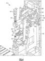
Fig. 2 is a simplified perspective view of a welding system embodiment without guarding or material handling; -
Fig. 3 is a simplified perspective view of a welding machine; -
Fig. 4 is an enlarged perspective view of the resistance welding gun incorporated in the welding machine; -
Fig. 5A is another enlarged perspective view depicting the welding gun with a fastener feeder in a feeder retracted position, a pin in a pin retracted position, and an electrode in an electrode advanced position; -
Fig. 5B is an enlarged perspective view depicting the feeder in a feeder advanced position and the electrode in the electrode advanced position; -
Fig. 5C is an enlarged perspective view depicting the pin in a pin advanced position and the fastener feeder moving from the feeder advanced position to the feeder retracted position; -
Fig. 5D is an enlarged perspective view depicting the pin in the pin advanced position and the fastener feeder in the feeder retracted position; -
Fig. 6A is a perspective view of another feeder for loading a fastener; -
Fig. 6B is a top view of the feeder for loading a fastener with components removed to show an internal queue of fasteners; -
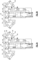
Fig. 7A is a top view of the resistance welding gun in the home position with one example homing assembly; -
Fig. 7B is a top view of the resistance welding gun positioned in a random location required to accommodate a welding position; -
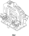
Fig. 8 is a top view of the resistance welding gun with another example homing assembly and illustrating the home position in solid lines and the random location in broken lines; -
Fig. 9 is a perspective view of the homing assembly shown inFig. 8 ; and -
Fig. 10 is a perspective view of a part conveyor with random workpiece placement. - The embodiments, examples and alternatives of the preceding paragraphs, the claims, or the following description and drawings, including any of their various aspects or respective individual features, may be taken independently or in any combination. Features described in connection with one embodiment are applicable to all embodiments, unless such features are incompatible.
- The disclosed system provides low-cost automation to weld fasteners, or secure other parts such as pins, clips, or brackets to sheet metal stampings at high speeds. The same system can be applied to other assembly processes such as rivets, self-piercing fasteners, mechanical fasteners to a variety of workpieces including those made of plastic. Thus, although the disclosed system is discussed primarily in terms of a welding system and method, it should be understood that other types of securing systems are contemplated.
- A
welding system 10 is schematically illustrated inFig. 1 . First andsecond conveyors robot 14 within awelding station 15. Therobot 14 transfers the parts from theconveyors welding machines welding machine 16a secures studs supplied by avibratory feeder bowl 17a, and theother welding machine 16b secures nuts supplied by avibratory feeder bowl 17b. The arrangement shown inFig. 1 is exemplary only and may be configured differently than illustrated. -
Fig. 2 shows oneexample welding system 10 for high-rate production in more detail that includes adrag conveyor 12, high-speed robot 14, weldingmachine 16, unloadchute 18, andcontrol system 20. Thedrag conveyor 12 provides a number of equally spaced load stations, each having a transfer pins 110 for engaging a workpiece to which a component such as a fastener will be welded. Thedrag conveyor 12 advances workpieces loaded by an operator onto transfer pins 110 at one end towards an unload end (shown in more detail inFig. 10 ). The high-speed robot 14 is positioned in close proximity to the unload end of thedrag conveyor 12 where it will grasp a workpiece and thewelding machine 16 to which it will present the workpiece for welding. Acontrol system 20 is interconnected to each of the elements of thewelding system 10 to provide functional control and coordination of the motions of the elements to minimize the operating cycle time. In one example, thewelding system 10 may be configured to weld than thirty or more different assemblies. Thecontrol system 20 maintains data for each assembly needed to manage the position and number of fasteners in each assembly, instructions for when the robot can release the assembly, error recovery protocols, weld signatures, and other information for automating the welding of the assembly. - With continuing reference to
Fig. 2 , thewelding system 10 is configured to accept a workpiece W (Fig. 10 ) such as a sheet metal stamping and weld a component part to it, such as a fastener F (e.g.,Figs. 5A-6B ), in the shortest time possible. The individual stations of adrag conveyor 12 include atransfer pin 110 which engages in a hole in the workpiece to pull the workpiece W from the loading point to an unloading point. The geometry and mass of the workpiece W will determine its attitude when resting on thedrag conveyor 12 and engaged with thetransfer pin 110. Friction between the bed of thedrag conveyor 12 and the workpiece W is sufficient to urge all of the workpieces into a sufficiently consistent orientation as they are moved towards the unload position. - The number and spacing of the transfer pins 110 will determine the length and width of the
drag conveyor 12. The diameter of the transfer pins 110 is selected to engage the hole in the range of workpieces to be welded, have sufficient strength to minimize bending, and to provide some clearance between the hole and workpiece W so the high-speed robot 14 can reliably remove the workpiece W. The length of thetransfer pin 110 is based on the height above thedrag conveyor 12 where the workpiece engages thetransfer pin 110. The height of thedrag conveyor 12 depends on whether it is to be manually loaded at a convenient height for an operator, or by automation directly from the stamping equipment used in production of the workpiece. - The
welding system 10 shown inFig. 2 is includes adrag conveyor 12 having three rows of twenty four stations. The number of rows and stations depends on a number of factors such as permissible floorspace, workpiece loading time, welding sequence time, buffer inventory requirement, and interaction between workpieces in adjacent stations. - The high-
speed robot 14 is programmed to properly grasp the workpiece W from a station at the unload end of thedrag conveyor 12 and transition it to an attitude and position necessary to engage with thewelding machine 16. Since the tooling uses asimple transfer pin 110, there is no requirement beyond programming, for tooling or tool set-up to accommodate different workpieces. - The high-
speed robot 14 and thewelding machine 16 are coordinated by acontrol system 20 to engage the workpiece W with thewelding machine 16 as quickly as possible so the welding process can be completed and the completed assembly discharged from thewelding system 10. Thewelding machine 16 includes provisions, such as the float assemblies illustrated inFigs. 7A-9 , for accommodating some misalignment of the workpiece due to variation of the attitude of the workpiece on thedrag conveyor 12 and positioning error of the high-speed robot 14 plus any positioning error due to variations in the workpiece W, or movement of the workpiece W in the gripping device of the high-speed robot 14 during the workpiece transfer. - In further detail, with continuing reference to
Fig. 2 , the size and configuration of the welding system are suited to the range of assemblies to be welded. Thewelding machine 16 capability, including its physical size, welding current or power capability, and electrode force range are determined by the workpiece characteristics and the requirements of the welding process. The configuration and height of the unloadchute 18 is based on the type of container in which the completed weldment is discharging. - The
welding machine 16 shown inFig. 2 is a resistance welding machine configured for welding projection weld nuts. It could also be configured to weld projection weld studs, to weld by other means such as laser welding, or to perform other processes such as assembly. The versatility of thewelding system 10 can be expanded by incorporatingmultiple welding machines 16 that weld different sized fasteners F (e.g.,Figs. 5A-6B ) or different types of operations. These either can be located within easy reach of the high-speed robot, manually repositioned, or supplied with automation to index one ormore welding machines 16 to the active position within the reach of the high-speed robot 14. - The
welding machine 16 as shown inFig. 3 includes awelding machine frame 30 supporting a resistance welding gun 32 and afeeder 34 for delivering a fastener F to be welded to a workpiece W. Thewelding machine frame 30 maintains the alignment and orientation of the components and includes provisions for leveling to ensure the desired function. The resistance welding gun 32 supports aresistance welding transformer 36 to produce the required welding current and awelding actuator 38 for achieving the required coordinated motion of the welding electrodes and the necessary electrode force for welding. The resistance welding transformer can be of any type, such as alternating current or inverter. The resistance welding gun is oriented to exploit gravity to maintain engagement with the fastener F delivered by afeeder 34 as it is moved to the welding position. Thefeeder 34 dispenses one fastener F to be welded to the workpiece at a time onto themovable welding electrode 44. - The
feeder 34 shown is for feeding projection weld nuts. The design of thefeeder 34 will be based on the requirements of the fastener F to be welded and may for example be a stud, pin, or bracket; or other process such as feeding of a rivet, screw, clinch nut, mechanical clip, or other mechanical fastener. Thus, thewelding machine 16 can employ a process other than resistance welding or a process that does not involve such mechanical fastening involving riveting, self-piercing fastener, bolting, or the like. - The
welding machine frame 30 is rigid enough to ensure consistency of the resistance welding gun 32 position when the mass of the gun is shifting and when it is subjected to external forces. When a welding cycle is requested, the welding actuator 32 extends to a position that is aligned with thefeeder 34 when it advances to deliver a component to be welded. When thefeeder 34 retracts to its home or feeder retracted position, the welding actuator 32 extends fully to close the electrodes and press the fastener F to be welded against the workpiece W positioned by the high-speed welding robot 14. During the welding sequence, welding current delivered by theresistance welding transformer 36 creates the heat for welding. At the completion of the weld, the output of thewelding actuator 38 is retracted to return themoveable welding electrode 44 to its home or electrode retracted position. - The
welding machine frame 30 ofFig. 3 holds the resistance welding gun 32 at the required working height determined in large part by the required height of the unloadchute 18 or by clearance necessary to ensure there is no interference with the operation of the resistance welding gun 32. The resistance welding gun 32 is sized to accommodate the physical size of the workpiece W or workpieces, and the required electrode force and welding current. The stroke of thewelding actuator 38 is determined by the required resistance welding gun 32 opening and that in turn determines the length of thewelding actuator 38. - The configuration of the
welding machine frame 30 illustrated inFig. 3 is a generic design for illustration purposes. Thewelding machine frame 30 can be a standardized version or a custom design created for a specific application. Thewelding machine frame 30 can stand alone, it can be mounted to a frame that supports the other components of thewelding system 10, or it can be incorporated into a larger piece of equipment providing multiple functions. The C-type resistance welding gun 32 shown employs awelding actuator 38 that moves the electrode in a linear motion towards an opposing stationary welding electrode 48 (Fig. 4 ). Linear motion is desirable for projection welding because it is most effective for providing consistent force on each projection and to follow the projection collapse during the weld. - The resistance welding gun 32 can be of any design, construction or material that achieves the requirements for the particular project scope. The welding actuator illustrated is an electric servo type but it could also be a pneumatic cylinder with an intermediate stroke position, such as a retract cylinder or other similar device.
-
Fig. 4 shows elements of thewelding machine 16 in more detail. The resistance welding gun 32 includes two spaced apart welding gun side frames 40 and 42 that provide the main structure to hold the components of the gun, contain the welding force, and provide a means for mounting within thewelding machine 16. Amoveable welding electrode 44, containing a fastenerrough locating pin 46, is connected to the output shaft of thewelding actuator 38. Astationary welding electrode 48 containing afastener locating pin 50, opposes themoveable welding electrode 44. Thefastener locating pin 50 is actuated by a locatingpin cylinder 52 and its position is sensed by a locatingpin position sensor 53. - Examples relating to suitable pin position sensing can be found in
USPN 6,576,859, entitled "Resistance Welding Fastener Electrode," issued June 10, 2003 and PCT International Application No.PCT/CA2014/050896, entitled "Welder with Indirect Sensing of Weld Fastener Position", filed September 18, 2014 - The sensor(s) can be used to track the electrode and welding pin movement to monitor situations that might generate an error leading to a defective part or a fault in the
welding system 10. For example, if the pin locating the fastener is depressed when the welding gun closes on the workpiece presented by the robot, the workpiece may not have a clearance hole, or the workpiece may have slipped in the robot gripper too far for the floating action of the welding unit to accommodate (discussed in more detail below). Thecontrol system 20 in this case can instruct therobot 14 to deliver the workpiece to a containment area and pick up a new workpiece from thedrag conveyor 12. In another example, if the electrode is not closed to the expected height, there may be an improper workpiece, fastener, or perhaps two fasteners. In this scenario, the system may first try to eject the fastener and reload. If the same error occurs, the workpiece is replaced as above. - The
stationary welding electrode 48 andfastener locating pin 50 are specifically designed to suit the thickness of the workpiece W plus the clearance hole and fastener F locating diameter. Thefastener locating pin 50 needs to be designed with gentle and smoothly transitioned curves to help urge the resistance welding gun 32 into the correct position. Excessive roughness, sharp angles, or steps on thefastener locating pin 50 may cause the pin to hang up on the workpiece, thereby inhibiting the locatingpin cylinder 52 from advancing thefastener locating pin 50 to its fully extended position. Significant deviation of the workpiece W hole location can be accommodated by this arrangement. The maximum deviation would be in the range of 40% of the fastener thread being gaged. Our demonstration system is somewhat higher - providing a 5 mm window of compensation for a fastener having an 8 mm thread. - The stroke and force capability of the locating
pin cylinder 52 needs to be sufficient to overcome the force applied to the fastenerrough locating pin 46 in themovable welding electrode 44. - The resistance welding gun 32 is connected to the
machine frame 30 by one ormore float assemblies 59 which permit motion within a plane. For simplicity, the description of one mechanism will be described althoughFig. 4 shows there is one such mechanism located on opposing sides of the resistance welding gun 32. The planar alignment ofbracket 54 on frame with thebracket 56 on welding unit is provided bylink 58 to frame and link 60 to welding unit. Pins and bearings are provided at the attachment points between the components of this mechanism to enable welding gun 32 to float freely relative to theframe 30. A homingassembly 61 includes a homingactuator 66 that engages guide pins 62 and 64 to urge the resistance welding gun to a fixed home position that is the nominal position of thefastener locating pin 50 where the high-speed robot 14 has been programmed to position the clearance hole for thefastener locating pin 50. Thefloat assembly 59 and homingassembly 61 illustrated inFig. 4 are shown in more detail inFigs. 7A-7B . Alternative configurations are illustrated inFigs. 8-9 . - The resistance welding gun 32 of
Fig. 4 provides clearance between the welding gun side frames 40 and 42 to accommodate thefeeder 34. Like the welding gun side frames 40 and 42, thefeeder 34 represents a potential point of interference between the resistance welding gun 32 and the workpiece or high-speed welding robot gripper so it is desirable to keep it out of the way and this is accomplished by putting it in the throat of the resistance welding gun 32. Thefeeder 34 is commonly provided with components, such as fasteners, from an automatic feeding system by way of a tube, track, or carrier (e.g.,vibratory feeder bowls Fig. 1 ). The feed path required to accommodate this apparatus can be quite long and it can be provided for and accommodated within thewelding machine frame 30. - To load the component such as a fastener, the rod of the
welding actuator 38 is advanced (with thefeeder 34 in the feeder retracted position) to raise themovable welding electrode 44 to the electrode advanced position (Fig. 5A ) necessary to interact with thefeeder 34. Thefeeder 34 advances in a linear motion to a feeder advanced position (Fig. 5B ) where the fastener is aligned with the fastenerrough locating pin 46. At this time, the fastenerrough locating pin 46 is advanced to its fully extended pin advanced position (Fig. 5C ) to capture the fastener. Then thefeeder 34 is withdrawn to its home feeder retracted position (Fig. 5D ), the action of which causes thefeeder 34 to release the fastener on the fastenerrough locating pin 46. With thefeeder 34 clear of themoveable welding electrode 44, thewelding actuator 38 is free to advance themoveable welding electrode 44, as soon as the high-speed welding robot 14 confirms it has placed a workpiece over thefastener locating pin 50 in thestationary welding electrode 48. -
Fig. 6A is a perspective view of thefeeder 34. Thefeeder mounting plate 78 is used to establish a fixed position relative to the resistance welding gun 32 orwelding machine frame 30. Aslide bar 82 engages aslide body 84 to which an escapement assembly is mounted so it can move between a returned position and an advanced position, which corresponds to feeder retracted and feeder advanced positions. The two articulatingjaws springs top plate 100 and bottom plate cooperate with thejaws rough locating pin 46.Fig. 6B is a top view of thefeeder 34 with theclamp arm 96,clamp pad 98, andtop plate 100 removed to show fastener F, retained fastener F2, and other fasteners queued for feeding to thewelding machine 16. Aclamp cylinder 94 drives aclamp arm 96 that supports aclamp pad 98 to capture retained fastener F2 which is immediately adjacent and in contact with the fastener F which will be loaded onto the fastenerrough locating pin 46. - The
feeder 34 ofFig. 6A and 6B , receives fasteners from an external system that sorts, orients and delivers fasteners. When themoveable welding electrode 44 is in position to receive a fastener F, a signal is given by thecontrol system 20 to actuate theadvance cylinder 80. Theslide body 84 moves along theslide bar 82 to advance the escapement mechanism into the position where the hole in fastener F will align with the fastenerrough locating pin 46. Thecontrol system 20 provides a signal to operateclamp cylinder 94 which drives clamparm 96 to pressclamp pad 98 against retained fastener F2. When the advanced position has been reached, thecontrol system 20 provides a signal to advance the fastenerrough locating pin 46 to its fully extended position at which it engages the fastener F. At this point in the sequence, theadvance cylinder 80 retracts. The engagement of the fastenerrough locating pin 46 with fastener F prevents fastener F from moving. The force of fastener F transferred tojaws springs feeder 34 therefore returns to a position clear of themoveable welding electrode 44, after having deposited fastener F on the fastenerrough locating pin 46.Advance cylinder 80 retracts to release theclamp pad 98 to release retained fastener F2 so that it can advance to the position of fastener F. - The size and configuration of
feeder 34 must be appropriate for the dimensions and requirements of a specific fastener F. Such fasteners are widely varied in thread type, size, and length; and other attributes such as pilot diameters, stepped faces, number and type of projections. The shape of thejaws jaws advance cylinder 80 retracts. The size of theclamp pad 98 and the length ofclamp arm 96 will depend largely on the diameter or effective size of the fasteners F and F2 so that fastener F2 is properly retained and there is no interference with fastener F that impairs the reliability of its ejection and placement. For suitable operating life, the components of thefeeder 34 in contact with the fasteners need to be made of hardened materials that resist wear from impact and sliding friction. The cycle time of this feeding operation is very fast - typically 0.3 seconds or less. - While
Fig. 6A and 6B illustrate a fastener F that is a projection weld nut for resistance welding, the component could be any of a variety including a pin, stud, or bracket. The shape of thejaws clamp pad 98 would be similarly changed to match the requirements to secure the retained fastener F2. This may involve for example, a pin to engage the hole in retained fastener F2 or a barrier to impede the travel of fastener F2 or provide separation between the retained fastener F2 and fastener F. - In another example, the
clamp cylinder 94,clamp arm 96 andclamp pad 98 may be eliminated (as shown inFigs. 5A-5D ). In this case, gravity urges the fasteners F to the end of thefeeder 34. Thecontrol system 20 tracks the number of fasteners F inside thefeeder 34, which is determined by the fastener size, to ensure a sufficient urging force. Since the releasing operation happens so fast, with theclamp jaws - While waiting to receive the workpiece from the high-
speed robot 14, the resistance welding gun is locked into a fixed position by the homingactuator 66 advancing over guide pins 62 and 64, as shown inFigs. 4 and7A-7B . This fixed position provides the high-speed robot with a target to align the fastener clearance hole in the workpiece W with thefastener locating pin 50 in thestationary welding electrode 48. Once the high-speed robot 14 has completed the transit to the load position, the workpiece W will be in close proximity or resting against thestationary welding electrode 48. The homingactuator 66 is then retracted to permit the resistance welding gun 32 to move freely in the plane of the weld. When the locatingpin cylinder 52 advances thefastener locating pin 50 through workpiece W, any misalignment between thefastener locating pin 50 and the hole in the workpiece W will cause a force on one side of the locatingpin 50. This force will urge the resistance welding gun 32 to move in the plane of the weld into a compliant position where thefastener locating pin 50 is centered in the hole in the workpiece W and engaged with the fastener F on the other side. To fully extend, thefastener locating pin 50 must push the fastenerrough locating pin 46 out of the fastener F and back into themoveable welding electrode 44. The locatingpin position sensor 53 verifies that thefastener locating pin 50 has reached the desired stroke extension and the displacement conforms with expectations. - To move the resistance welding gun 32 relative to the fixed
welding machine frame 30, the distance between thebracket 54 on frame andbracket 56 on welding unit will change. The change in the mounting bracket distance is easily accommodated by changing the angle between thelink 58 to frame and link 60 to welding unit. The link towelding unit 60 incorporates provisions for adjusting the tension against the link to frame to ensure there is not excessive binding or looseness that impairs the function of thefloat assembly 59. - For small assemblies, where the mass of the part is unlikely to affect the welding process, when the electrodes are closed on the workpiece W and fastener, the high-
speed robot 14 may release the workpiece W to return to thedrag conveyor 12 for another workpiece W. If there is an additional fastener F or fasteners to be welded, or the mass of the weldment is too much, the high-speed robot 14 will continue to hold the workpiece W. Then the welding process is completed to secure the fastener W to the workpiece W. If the assembly weldment was released, the action of opening the resistance welding gun 32 by retracting thewelding actuator 38 will free the welded assembly to fall onto the unloadchute 18 to be discharged from the machine. - If there is a requirement to weld additional fasteners the
feeder 34 operating sequence and welding sequence can be repeated as soon as themoveable welding electrode 44 has returned to thefeeder 34 cycling position. If the welding is complete, the high-speed robot 14 can move the assembly to the position where it can be released. - The force and stroke of the homing
actuator 66 needs to be sufficient to engage the guide pins 62 and 64 urge the resistance welding gun 32 back to its home position. The travel speed of the homingactuator 66 and the shape of the guide pins 62 and 64 determine the rate at which the resistance welding gun 32 moves. - The mechanism for enabling the resistance welding gun 32 to move in the plane of the weld could be an air bearing or low-friction X-Y slide assembly. Other means for placing the fastener on the movable electrode can be used such as conventional spear type fastener loader. The homing
actuator 66 and arrangement of guide pins 62 and 64 represents one way to guide the resistance welding gun 32 back to its home position. Tapered pins, wedges and expanding arbors or guides are examples of other devices for centering two items that are displaced from one another in one plane. - When the position of the hole provided in the workpiece W for access to the fastener F thread is not sufficiently accurate to be used for establishing the welding position of the fastener F, such as when the hole is cut by a laser slightly out of position, the principles of
Fig. 4 can be applied to an external device which accomplishes the same function of urging the resistance welding gun 32 to a desired location, using a different hole or attribute of the workpiece W as a reference. In this case, another supplemental pin, performing the location function of thefastener locating pin 50 can be attached and driven by a supplemental actuator so that it can engage a hole or attribute of the workpiece that is desired for establishing the position of the fastener F in relation to the workpiece W. The supplemental actuator would advance the supplemental pin to engage the workpiece W. The shape of the pin would be selected to urge the resistance welding gun into the proper position for welding when it engages the workpiece W. Relocation of this function to the supplemental actuator and pin would not affect the ability of thefastener locating pin 50 to provide the function of monitoring and detecting the fastener F. -
Fig. 7A is a top view of the resistance welding gun 32 in its home position with the guide pins 62 and 64 engaged in the homing guides 68 and 70 respectively. Each of the homing guides 68 and 70 provides a cylindrical hole corresponding to a 2-dimensional position within the plane of movement. The two homing guides 68 and 70 work together to fix the position of thefastener locating pin 50 which the high-speed robot 14 will target for workpiece placement in thenext welding machine 16 operating cycle. -
Fig. 7B is a top view of the resistance welding gun 32 in a position where the guide pins 62 and 64 are no longer engaged or aligned with the homing guides 68 and 70 respectively. This position is achieved when the homingactuator 66 retracts the guide pins 62 and 64 from the homing guides 68 and 70 and force applied on thefastener locating pin 50 urges the resistance welding gun 32 into such an alignment. The difference in position of the resistance welding gun 32 inFigure 7A and Figure 7B is not visible in these figures. - When the homing
actuator 66 is activated to return the resistance welding gun 32 to its home position, the homing guides 68 and 70 will be forced against and over the guide pins 62 and 64 respectively. In the position where the homingactuator 66 is fully advanced, the guide pins 62 and 64 will be securely contained by the homing guides 68 and 70, as inFig. 7A . - The homing guides 68 and 70 provide a cylindrical hole to establish a 2-dimensional position within the plane of movement and the two cooperate together to establish the home position of the resistance welding gun 32. The diameter of the cylindrical holes is determined by the diameter of the guide pins 62 and 64 with a minor amount of clearance necessary to ensure a slip fit. The guide pins 62 and 64 need to have a diameter sufficient to resist bending and a length accommodating the desired rate transition from the small diameter tip to the full diameter. The small diameter of the tip determines the maximum guide pin displacement at which the guide pins 62 and 64 can enter the homing guides 68 and 70. In most cases, the guide pins 62 and 64 and homing guides 68 and 70 should be hardened and have a low friction coating to prevent galling and binding. The spacing and position of the homing guides 68 and 70 is a function of the resistance welding gun 32 and the distance from the center of the homing guides 68 and 70 to the center of the
fastener locating pin 50. The homingactuator 66 must have a force and travel speed sufficient to realign the guide pins 62 and 64 and homing guides 68 and 70 quickly and without excessive shock. - The hardware used to fix the position the resistance welding gun 32 can involve other approaches than described. For example, wedges or cams could be used in place of guide pins 62 and 64. The homing guides 68 and 70 could also be split lengthwise to close onto the guide pins 62 and 64 to reduce friction. Using such an approach, the solid guide pins 62 and 64 could be surrounded or replaced with rollers to further reduce friction during repositioning.
- Another homing
assembly 161 is shown inFigs. 8 and9 . The homingassembly 161 uses a pair of homing guides 168, 170 that respectively cooperate with guide pins 162, 164 to locate the welding unit to the home position. In the example, afirst homing actuator 166 actuates a pair ofarms 169 into engagement with opposing sides of theguide pin 162 to clamp theguide pin 162 and locate one side of the welding unit in a first direction within the horizontal plane. Asecond homing actuator 167 actuates a pair ofarms 171, which includenotches 173, into engagement with opposing sides of theguide pin 164 to clamp theguide pin 164 and locate the other side of the welding unit in both first and second directions within the plane. The first andsecond actuators arms -
Fig. 10 is a perspective view of thedrag conveyor 12 with the addition of a number of workpieces W. The workpieces W are engaged on number of evenly spaced transfer pins 110 are affixed toconveyor chains 112. Threesuch conveyor chains 112 are supported and driven by a sprocket assembly at each end of thedrag conveyor 12. Theconveyor chains 112 are aligned with spaces provided between adjacent friction bars 116 to permit the travel of the transfer pins 110 and thereby the workpieces W. - The workpiece W shown in
Fig. 10 is used to illustrate the principles of operation and is not representative of the range and size of permissible workpieces W. While not defined in the hardware, a number of zones are illustrated inFig. 10 to explain the operation of thedrag conveyor 12. An operator loading zone A, is within easy reach of an operator who will manually sort, orient, and place a workpiece W so the selected attribute of the workpiece W, such as a specific hole, engages atransfer pin 110. Within zone A, the orientation of the workpiece W is not required to be precise and the number of occupied transfer pins 110, as well as the sequence in which they are loaded is not important. Thesprocket assembly 114 drives theconveyor chains 112 to advance the transfer pins 110 towards the unloading zone C. Along the length of the drag conveyor there is a workpiece orientation zone B in which the friction of the workpiece W acting against thefriction bar 116 urges the workpiece W into a generally consistent orientation. Also illustrated is an empty zone B1 which corresponds to a time when the operator was unable to load a workpiece W. This could be for any number of reasons such as when convenient access to workpieces W is not possible. This could occur when there is an interruption of the supply of workpieces, such as might occur when the container holding them is empty and requires replacement. In the oriented part zone B2 the workpieces are progressively oriented such that when leaving this zone and entering the unloading zone C, they are in a position identifiable by the high-speed robot 14. - In the unloading zone C, a detection method would be employed so the
control system 20 can communicate the workpiece W location to the high-speed robot 14. The detection method could be an inductive proximity switch, photo switch, laser, or imaging system. The detection method could detect and verify the workpiece W in the unloading zone C each of the transfer path, or it could be incorporated into the high-speed robot 14 tooling that is used to capture the workpiece W for loading into the welding machine. Thedrag conveyor 12 would be advanced to position at least one workpiece W in the unloading zone C within reach of the robot. The high-speed robot 14 could wait until a workpiece W has reached a fixed unloading position, or it could capture the workpiece while it is moving within the unloading zone C if thedrag conveyor 12 and high-speed robot 14 are operated in coordinated motion. - The detection method employed to detect and verify the workpiece W is within the unloading zone C can also be used to verify an attribute of the workpiece W so that a misaligned or incorrect workpiece W can be discharged from the
drag conveyor 12 simply by moving it past the point at which the workpiece W remains engaged with the friction bars 116 andtransfer pin 110. - The
conveyor frame 118 shown inFig. 10 is illustrative only. It can be a freestanding unit as shown or integrated with the frame supporting other components of thewelding system 10. The number and length ofconveyor chains 112 is dependent on the number and spacing of transfer pins 110 required to support thewelding system 10 operating requirements. The transfer pins 100 may not have a circular cross section and of any length required to engage the workpiece W while it is resting on a surface. The length and definition of the illustrateddrag conveyor 12 zones is a function of thewelding system 10 operating requirements and other factors such as machine guarding, and the duration of friction application required to ensure the workpieces W are consistently oriented. Thefriction bar 116 would commonly be made of sheet or plate steel with a width, length, and thickness suited to the size of the workpiece W. Instead of changing the length of transfer pins 110 to suit different workpieces W, provision can be made to change the spacing between thefriction bar 116 andconveyor chain 112. - The
drag conveyor 12 shown inFig. 10 is an example configuration. The transfer path does not need to be linear as illustrated. The transfer path could be circular as a rotary table, a serpentine shape, or have transitions to different shapes along the length of travel. The transfer path also does not need to be in one plane or in a plane parallel to the floor. Theconveyor chain 112 can be driven by any number of means such as the high-speed robot 14 controller to provide for coordinated motion, a speed-controlled motor, or a ratcheting drive connected to a pneumatic cylinder. The friction bars 116 can be made of any number of metal, other material such as self-healing polymer, or a combination of materials. The friction bars 116 may also be supplemented with risers or guides if, for example, they are beneficial to speed up workpiece W orientation, reduce the chance the workpiece W will lock on thetransfer pin 110, or prevent motion that would cause interference between adjacent workpieces W. The space between friction bars could be occupied withconveyor chain 112 link, accessory, or cover that prevents the workpiece W from engaging with the gap between adjacent friction bars 116 if the such engagement would prevent the workpiece W from moving to the desired alignment. - An example operating sequence of each of the
principle welding system 10 components is as follows. The equipment operator or automation will load workpieces on thedrag conveyor 12 whenever there is an available station within reach. Thedrag conveyor 12 will advance workpieces W towards the unloading zone C whenever there are no workpieces W properly oriented for pick-up within the unloading zone C. The high-speed robot 14 will move to position to engage a workpiece W when it is free to begin the transfer sequence and a workpiece W has been detected in an orientation conducive to engagement. When the resistance welding gun 32 is opened sufficiently to accept the high-speed robot 14 to load a workpiece W, the high-speed robot 14 will move the workpiece W to a position in alignment with thestationary welding electrode 48. Independently, or simultaneously with the operation of the high-speed robot 14, when themoveable welding electrode 44 has been moved by thewelding actuator 38 to the position to receive the fastener F from thefeeder 34, thefeeder 34 will advance to the location in which the fastener F is aligned withmovable welding electrode 44. The fastenerrough locating pin 50 is then advanced to engage with the fastener F while theclamp arm 96 advances to bring theclamp pad 98 into contact with the retained fastener F2. Thefeeder 34 is then retracted to its rest position, the action of which causes thejaws feeder 34 has retracted, the fastener F will be raised towards the workpiece W by themovable welding electrode 44 on which it is resting. When thewelding actuator 38 reaches the travel distance at which the workpiece W and fastener F should be in contact between themoveable welding electrode 44 andstationary welding electrode 48, homing guide pins 62 and 64 will be released from the homing guides 68 and 70. Thefastener locating pin 50 will then advance to monitor and verify the part position as well as to bring the parts to be welded, if present, into alignment by urging the resistance welding gun 32 to move. Thewelding machine 16 will perform the welding operation. When the workpiece W does not require an additional fastener F and can be supported by the welding electrodes, the high-speed robot 14 will disengage from the workpiece W and move to retrieve another workpiece W from thedrag conveyor 14. Otherwise, it will continue to hold and support the workpiece W until themoveable electrode 44 has retracted sufficiently to either permit the high-speed robot 14 to index the subassembly to the next welding position, or to release the completed assembly so it can exit thewelding system 10. Thewelding actuator 38 will return themoveable welding electrode 44 to its fully lowered position to begin the fastener feeding and welding cycle over again. - The disclosed welding system welds fasteners at high speeds to maximize labor productivity while reducing complexity to minimize downtime and capital cost. Both the equipment and operator productivity are improved by freeing the operator from having to load components synchronously with the welding machine cycle. When the operator can grab a number of workpieces from the storage bin and load them into the equipment at a higher rate than the equipment cycle time, the time required for the operator to get more workpieces from the bin can be buried in the system cycle time so the welding process can proceed at the maximum production rate of the welding machine.
- Maximizing the production rate allows the capital cost of the welding machine or assembly processes to be amortized over more assemblies. In addition to the labor savings that comes from increasing the rate of production welding, increased production volume provides an opportunity to amortize the cost of any supplemental error avoidance systems over more assemblies.
- The system provides sufficient speed, versatility, and reliability to be located in the stamping bay where the stampings are produced or where injection molding occurs to eliminate storage of inventory and extra material handling.
- It should also be understood that although a particular component arrangement is disclosed in the illustrated embodiments, other arrangements will benefit herefrom. Although particular step sequences are shown, described, and claimed, it should be understood that steps may be performed in any order, separated or combined unless otherwise indicated.
- Although the different examples have specific components shown in the illustrations, embodiments of this invention are not limited to those particular combinations. It is possible to use some of the components or features from one of the examples in combination with features or components from another one of the examples.
- Although an example embodiment has been disclosed, a worker of ordinary skill in this art would recognize that certain modifications would come within the scope of the appended claims.
Claims (15)
- A securing system comprising:a robot (14) configured to transfer a workpiece (W) to a home position;a securing station includes:a frame (30);a gun (32) supported on the frame (30), the gun (32) includes a stationary welding electrode (48) and a moveable welding electrode (44), the moveable welding electrode (44) opposing the stationary welding electrode (48), the gun (32) is suitable to secure a component to the workpiece (W) in a securing position during a securing operation; anda float assembly (59) interconnects the gun (32) to the frame (30), the float assembly (59) suitable to permit the gun (32) to glide relative to the frame (30) between the home position and the securing position, wherein the stationary welding electrode (48) comprises a locating pin (50) and a locating pin cylinder (52), and wherein, in use, when the locating pin cylinder (52) advances the fastener locating pin (50) through the workpiece (W), any misalignment between the fastener locating pin (50) and a hole in the workpiece (W) will cause a force on one side of the locating pin (50), which will urge the resistance welding gun (32) to move in a plane of the weld into a compliant position where the fastener locating pin (50) is centered in the hole in the workpiece (W) and engaged with the fastener (F) on the other side;a homing assembly (61, 161) includes a homing guide (68, 70) suitable to release the gun (32) from the home position during the securing operation and a homing actuator (66) which, when retracted, permits the resistance welding gun (32) to move freely in the plane of the weld.
- The system according to claim 1, wherein the securing station is a welding station (15) that includes a feeder (34) supported by the frame (30), the feeder configured to slide relative to the home position between feeder advanced and feeder retracted positions, the component is arranged over the second electrode in the feeder advanced position.
- The system according to claim 2, wherein the feeder (34) is configured to provide the component to the gun (32) with the moveable welding electrode (44) in an electrode advanced position, and the component is a fastener.
- The system according to claim 3, wherein the moveable welding electrode (44) is movable between electrode retracted and electrode advanced positions.
- The system according to claim 4, wherein the stationary welding electrode (48) includes a fastener rough locating pin (46) movable between pin advanced and pin retracted positions with the moveable welding electrode (44) in the electrode advanced position.
- The system according to claim 5, wherein the fastener rough locating pin (46) is configured to engage a component with the feeder (34) in the feeder advanced position and the fastener rough locating pin (46) in the pin advanced position, and optionally
wherein the feeder (34) is configured to move from the feeder advanced position to the feeder retracted position with the component loaded on the pin (46), the system comprising a release mechanism wherein, the component is configured to be released by the release mechanism when moving to the feeder retracted position. - The system according to claim 6, wherein the feeder (34) includes opposing jaws (86, 88) biased to a component retaining position by springs (90, 92), wherein the jaws (86, 88) are configured to release the component and overcome the springs (90, 92) as the feeder (34) moves from the feeder advanced position to the feeder retracted position, and optionally
wherein the feeder (34) includes a clamp (96) configured to retain a second component behind a first component, the first component is loaded on the fastener rough locating pin (46), the clamp (96) is configured to cycle and permit the second component to advance to the jaws (86, 88) for subsequent loading onto the fastener rough locating pin (46). - The system according to claim 1, wherein the float assembly (59) includes links (58, 60) that interconnect the gun (32) to the frame (30), the links (58, 60) configured to permit the gun (32) to move in a horizontal plane, orwherein the homing assembly (61, 161) includes a pin (62, 162) that selectively cooperates with a guide (68, 168) to retain the gun (32) in the home position, and optionallywherein the guide (161) includes arms (169) that selectively engage the pin (168) to locate the gun (32) within a horizontal plane.
- The system according to claim 1, comprising a control system (20), wherein the control system (20) is configured to evaluate a position of the moveable welding electrode (44) and a pin (46) to identify, contain, and remediate workpiece and operating fault conditions, and optionally
wherein the control system (20) contains a schedule of parameters corresponding to a number of assembly configurations. - A method of manufacturing an assembly using a securing system according to any preceding claim, the method comprising the steps of:loading a workpiece (W) into an assembly station (10);permitting the assembly station (10) to float in two directions relative to the workpiece (W); andsecuring a component to the workpiece (W) at the assembly station (10) while performing the permitting step.
- The method according to claim 10, wherein the component is a fastener (F), the assembly station is a welding station (10), and the securing step includes welding the fastener (F) to the workpiece (W).
- The method according to claim 10, wherein the loading step includes the step of robotically transferring the workpiece (W) to the assembly station (10) with the assembly station (10) in a home position, and the permitting step includes releasing the assembly station from the home position subsequent to performing the step of robotically transferring the workpiece (W).
- The method according to claim 12, comprising the step of loading the component onto the moveable welding electrode (44) with a feeder (34), and retracting the feeder (34) subsequent to the component loading step, the feeder retracting step performed prior to the permitting step.
- The method according to claim 13, comprising at least one of:the step of advancing the moveable welding electrode (44) to engage the workpiece (W) during the permitting step; orwherein the component is a first component, and comprising the step of clamping a second component in the feeder (34), and releasing the first component during the feeder retracting step, and performing the step of unclamping the second component, orwherein the feeder retracting step includes overcoming spring biased jaws (86, 88) in the feeder (34).
- The method according to claim 12, comprising the step of picking up the workpiece (W) off of a drag conveyor (12) prior to the workpiece loading step.
Applications Claiming Priority (2)
| Application Number | Priority Date | Filing Date | Title |
|---|---|---|---|
| US201462020064P | 2014-07-02 | 2014-07-02 | |
| PCT/CA2015/050614 WO2016000077A1 (en) | 2014-07-02 | 2015-07-02 | System and method with floating welder for high rate production welding |
Publications (4)
| Publication Number | Publication Date |
|---|---|
| EP3164241A1 EP3164241A1 (en) | 2017-05-10 |
| EP3164241A4 EP3164241A4 (en) | 2018-04-11 |
| EP3164241B1 true EP3164241B1 (en) | 2025-01-15 |
| EP3164241C0 EP3164241C0 (en) | 2025-01-15 |
Family
ID=55018190
Family Applications (2)
| Application Number | Title | Priority Date | Filing Date |
|---|---|---|---|
| EP15814446.9A Active EP3164346B1 (en) | 2014-07-02 | 2015-07-02 | System and method with drag conveyor for high rate production welding |
| EP15815660.4A Active EP3164241B1 (en) | 2014-07-02 | 2015-07-02 | System and method with floating welder for high rate production welding |
Family Applications Before (1)
| Application Number | Title | Priority Date | Filing Date |
|---|---|---|---|
| EP15814446.9A Active EP3164346B1 (en) | 2014-07-02 | 2015-07-02 | System and method with drag conveyor for high rate production welding |
Country Status (7)
| Country | Link |
|---|---|
| US (4) | US9895775B2 (en) |
| EP (2) | EP3164346B1 (en) |
| CN (4) | CN110883414B (en) |
| BR (2) | BR112017000033B1 (en) |
| CA (2) | CA2932033A1 (en) |
| MX (2) | MX378657B (en) |
| WO (2) | WO2016000076A1 (en) |
Families Citing this family (45)
| Publication number | Priority date | Publication date | Assignee | Title |
|---|---|---|---|---|
| US9666465B2 (en) * | 2013-12-12 | 2017-05-30 | Seagate Technology Llc | Positioning apparatus |
| US10120364B2 (en) * | 2015-03-27 | 2018-11-06 | GM Global Technology Operations LLC | Self-corrective nut running for robotic applications |
| EP3199288B8 (en) | 2016-01-28 | 2024-05-29 | Böllhoff Verbindungstechnik GmbH | Element supply device of a setting welding device, a setting welding device as well as a connection method in the form of a mechanical thermal setting welding process |
| CN106735813B (en) * | 2016-12-26 | 2020-10-02 | 宁波宏协承汽车部件有限公司 | Spot welder base mechanism |
| CN106914693A (en) * | 2017-03-10 | 2017-07-04 | 清远诺巴特智能设备有限公司 | A kind of welding handgrip of highly automated regulation |
| CN107239650A (en) * | 2017-04-12 | 2017-10-10 | 同济大学 | Mixed flow is welded system complexity computational algorithm and complexity identifing source diagnostic method |
| DE102017004095A1 (en) * | 2017-04-28 | 2018-10-31 | Iwk Verpackungstechnik Gmbh | Tube transfer device in a tube filling machine and method for its control |
| US10807148B2 (en) * | 2017-06-20 | 2020-10-20 | Fca Us Llc | Upset protrusion joining and forging gun therefor |
| JP7116901B2 (en) * | 2017-08-01 | 2022-08-12 | オムロン株式会社 | ROBOT CONTROL DEVICE, ROBOT CONTROL METHOD AND ROBOT CONTROL PROGRAM |
| CN107253206B (en) * | 2017-08-03 | 2023-05-23 | 长春理工大学 | Industrial robot fixed resistance spot welding pliers electrode cap milling and replacement system |
| CN109896297B (en) * | 2017-12-08 | 2021-03-16 | 泰科电子(上海)有限公司 | Automatic feeding system |
| MX2020012338A (en) | 2018-06-06 | 2021-01-29 | Doben Ltd | Magnetic workpiece conveyor for robotic welding cell. |
| CN108857007A (en) * | 2018-09-10 | 2018-11-23 | 成都众凯汽车零部件制造有限公司 | A kind of groove workpiece automatic soldering device |
| US11654517B2 (en) | 2018-09-11 | 2023-05-23 | Jr Automation Technologies, Llc | Fastener welding apparatus |
| JP7275276B2 (en) * | 2018-12-13 | 2023-05-17 | ハウメット エアロスペース インコーポレイテッド | Rivet distribution system and method of use |
| WO2020160675A1 (en) | 2019-02-08 | 2020-08-13 | Miralis Inc. | Robotic systems and methods for assembling furniture |
| CN110412942A (en) * | 2019-07-17 | 2019-11-05 | 华域汽车车身零件(上海)有限公司 | One kind switching automatic error system for white body flexible frock |
| CN110421245A (en) * | 2019-08-22 | 2019-11-08 | 上海兰盈智能科技有限公司 | Multistation quick-changing type projection welding part fixture mounting structure and automatic welding mode |
| CN110524214B (en) * | 2019-09-10 | 2023-11-17 | 芜湖全程智能科技有限公司 | Device and method for mounting lower electrode plate of automobile PTC water heater |
| CN110560953B (en) * | 2019-09-24 | 2024-01-26 | 杭州中久自控系统有限公司 | Automatic welding equipment for liquid accumulator |
| US20230047883A1 (en) * | 2020-02-04 | 2023-02-16 | Magna Exteriors Inc. | Flexible punch and weld system |
| CN111590308B (en) * | 2020-05-29 | 2021-10-08 | 成都优博创通信技术有限公司 | Processing table |
| CN111890030B (en) * | 2020-06-29 | 2022-03-29 | 中山市易恩自动化科技有限公司 | Full-automatic heating member equipment |
| CN112122853B (en) * | 2020-09-24 | 2024-10-01 | 辽宁忠旺特种车辆制造有限公司 | Framework vehicle suspension support assembly welding tool and machining system and method |
| KR102297520B1 (en) * | 2020-10-12 | 2021-09-02 | (주)삼성텍 | Welding automation system using heterogeneous nut of metal product for electric and combustion vehicle |
| CN112719547A (en) * | 2020-12-19 | 2021-04-30 | 河南中车重型装备有限公司 | Automatic positioning welding platform of resistance welding machine |
| CN112719710B (en) * | 2020-12-29 | 2022-11-01 | 泉州芸台科技有限公司 | Automatic welding bench of material loading |
| CN112850101B (en) * | 2021-01-22 | 2022-03-29 | 龙光电子集团有限公司 | an assembly system |
| CN113042948B (en) * | 2021-03-20 | 2022-10-14 | 寰宇东方国际集装箱(宁波)有限公司 | Container side plate production line |
| US12138772B2 (en) * | 2021-04-30 | 2024-11-12 | Divergent Technologies, Inc. | Mobile parts table |
| DE102021120555A1 (en) * | 2021-08-06 | 2023-02-09 | Eckold Gmbh & Co. Kg | Joining head for attaching a fastener to the surface of a component |
| CN113562435B (en) * | 2021-09-24 | 2021-12-07 | 四川大学 | High-efficient collator of medicinal bottle plug |
| CN113579623B (en) * | 2021-09-26 | 2021-11-30 | 江苏力腾机械有限公司 | Rapid positioning welding equipment for hardware accessories |
| CN113909721B (en) * | 2021-09-29 | 2022-12-02 | 长沙中创海通智能科技有限公司 | Device for welding closing plates of building templates |
| US20230135381A1 (en) * | 2021-11-01 | 2023-05-04 | Legacy Industries | Floating system and method for a tool |
| CN114193055B (en) * | 2021-12-17 | 2023-05-05 | 北京石油化工学院 | Multi-gun automatic welding device for precast concrete reinforced bars and welding system thereof |
| CN115156683B (en) * | 2022-08-22 | 2024-04-09 | 广州松兴电气股份有限公司 | Automatic feeding system for white car body projection welding production line |
| US12521787B2 (en) | 2022-11-15 | 2026-01-13 | Doben Limited | Self-piercing clinch fastener installation press |
| US12290890B2 (en) | 2023-02-16 | 2025-05-06 | Doben Limited | Automated floating insertion tool for push-in fasteners |
| CN116475640B (en) * | 2023-05-19 | 2024-01-05 | 广州中益机械有限公司 | Automatic welding robot's of auto parts device of going up |
| CN116713580A (en) * | 2023-06-01 | 2023-09-08 | 上海骏腾发智能设备有限公司 | Double head nut welding equipment |
| CN117066631B (en) * | 2023-10-13 | 2024-01-05 | 湖南凌特科技有限公司 | Continuous equipment of lamp pearl |
| CN117463937B (en) * | 2023-12-28 | 2024-04-05 | 山东固而美金属制品有限公司 | Automatic press riveting system |
| CN117697664A (en) * | 2024-01-02 | 2024-03-15 | 重庆长安汽车股份有限公司 | Locking device and positioning fixture |
| US12234853B1 (en) | 2024-07-19 | 2025-02-25 | Doben Limited | Nut feeder and installation machine |
Citations (5)
| Publication number | Priority date | Publication date | Assignee | Title |
|---|---|---|---|---|
| JPS5953275A (en) * | 1982-09-22 | 1984-03-27 | Nissan Motor Co Ltd | Method and device for automatic fixing of car parts |
| JPH0924474A (en) * | 1995-07-11 | 1997-01-28 | Nissan Motor Co Ltd | Spot welding equipment |
| US6720517B2 (en) * | 2001-07-23 | 2004-04-13 | Sumitomo Wiring Systems, Ltd. | Resistance welding head and resistance welding apparatus and method using the head |
| JP2007181848A (en) * | 2006-01-05 | 2007-07-19 | Shiroyama Kogyo Kk | Joining device |
| CN102873448A (en) * | 2011-07-12 | 2013-01-16 | 上海梅达焊接设备有限公司 | Self-adaption floatation pressure device for spot welding machine |
Family Cites Families (63)
| Publication number | Priority date | Publication date | Assignee | Title |
|---|---|---|---|---|
| US2685018A (en) | 1951-06-29 | 1954-07-27 | Gen Motors Corp | Automatic nut loading machine |
| US2843166A (en) | 1955-07-25 | 1958-07-15 | Gen Motors Corp | Stud transfer and holding means for a stud driving tool |
| US2905803A (en) | 1958-01-13 | 1959-09-22 | Gen Motors Corp | Nut loading and welding machine |
| US3233752A (en) | 1964-06-29 | 1966-02-08 | Western Electric Co | Automatic positioning and orienting apparatus |
| US3415350A (en) * | 1966-10-24 | 1968-12-10 | Fmc Corp | Article orienting apparatus |
| JPS5413073B2 (en) * | 1974-03-28 | 1979-05-28 | ||
| US4020316A (en) * | 1975-08-22 | 1977-04-26 | Fastener Industries Inc. | Method and apparatus for positioning nuts to be welded to a base |
| NL7705670A (en) * | 1977-05-24 | 1978-11-28 | Iwema Techniek B V | Conveyor moving crates along treatment stations - rotates crates through 90 degrees by stop in path between stations |
| US4215262A (en) | 1978-03-06 | 1980-07-29 | Conceptual Engineering | Automatic percussion welding apparatus with stud feed |
| CA1071566A (en) * | 1978-03-08 | 1980-02-12 | John W. Hoehn | Apparatus for orienting objects |
| JPS5656396A (en) | 1979-10-12 | 1981-05-18 | Hiroshi Makino | Robot for assembly |
| FR2557537B1 (en) * | 1984-01-03 | 1986-09-19 | Socomo La Chatelaine | APPARATUS FOR HANDLING BAGS OF FOOD PRODUCTS, ESPECIALLY BEVERAGES, FOR PACKAGING AFTER PASTEURIZATION |
| US4678073A (en) * | 1985-04-04 | 1987-07-07 | American Telephone And Telegraph Company, At&T Technologies, Inc. | Apparatus and methods for handling bulk arrays of articles |
| JPS6231616A (en) * | 1985-07-30 | 1987-02-10 | Nichiden Mach Ltd | Rodform work conveying method |
| JPS62286683A (en) * | 1986-06-05 | 1987-12-12 | Toyota Motor Corp | Projection welding equipment |
| GB2192572B (en) | 1986-07-17 | 1990-04-04 | Metal Box Plc | Method and apparatus for orientating can ends |
| US4789768A (en) | 1986-12-09 | 1988-12-06 | Toyota Jidosha Kabushiki Kaisha | Projection welder |
| JPS6444392A (en) * | 1987-08-10 | 1989-02-16 | Honda Motor Co Ltd | Assembly equipment for parts for lower section of car |
| US4929146A (en) | 1987-11-13 | 1990-05-29 | U.S. Philips Corporation | Manipulator |
| JPH0622553Y2 (en) * | 1989-12-19 | 1994-06-15 | トヨタ自動車株式会社 | Automatic welding equipment feeder |
| JP2509103B2 (en) * | 1991-02-23 | 1996-06-19 | 好高 青山 | Parts feeder |
| DE4142824C2 (en) | 1991-12-23 | 2000-06-29 | Windmoeller & Hoelscher | Device for turning workpieces lying flat and moving forward |
| JPH0677978U (en) | 1992-04-21 | 1994-11-01 | 株式会社三五 | Nut misalignment detection device in resistance welding machine |
| JPH06156721A (en) * | 1992-11-19 | 1994-06-03 | Fuji Electric Co Ltd | Plate swivel device |
| KR0151438B1 (en) * | 1992-12-04 | 1998-10-15 | 긴바라 요시로 | Automatic assembly device |
| JPH06183542A (en) * | 1992-12-15 | 1994-07-05 | Kao Corp | Method and device for position aligning bottle circumferential direction |
| JPH0712546B2 (en) | 1993-02-25 | 1995-02-15 | 矢島技研株式会社 | Resistance welder |
| FR2716874B1 (en) | 1994-03-03 | 1996-06-21 | Materiel Arboriculture | Conveying device for products, especially fruit, suitable for sorting said products according to predetermined selection criteria. |
| JP3392210B2 (en) * | 1994-04-18 | 2003-03-31 | 富士写真フイルム株式会社 | Component aligning device and component assembling device using the same |
| US5530218A (en) * | 1994-05-30 | 1996-06-25 | Amada Metrecs Company, Limited | Spot welding apparatus |
| JP2807725B2 (en) * | 1994-05-30 | 1998-10-08 | 株式会社アマダメトレックス | Electrode holding device for spot welding machine |
| GB9502930D0 (en) * | 1995-02-15 | 1995-04-05 | Starpoint Electrics Ltd | Vending machine |
| JP3094151B2 (en) | 1996-05-08 | 2000-10-03 | 矢島技研株式会社 | Resistance welding machine |
| US6163004A (en) | 1996-08-10 | 2000-12-19 | Yoshitaka Aoyama | Method of welding projection nut and apparatus therefor |
| NL1008841C2 (en) | 1998-04-08 | 1999-10-11 | Tno | Orientation mechanism. |
| US6283272B1 (en) * | 1998-12-14 | 2001-09-04 | Texas Instruments Incorporated | Automatic tube orientation apparatus |
| JP2000317644A (en) * | 1999-05-08 | 2000-11-21 | Yoshitaka Aoyama | Method for feeding parts to composite welding machine |
| US6481560B2 (en) * | 2000-06-08 | 2002-11-19 | Christopher L. Kearney | Robotic feeding system |
| CN1262385C (en) | 2000-12-13 | 2006-07-05 | 株式会社Smk | Welding devices for nuts or bolts |
| EP1400301A4 (en) | 2001-06-28 | 2007-01-24 | Yoshitaka Aoyama | Method and device for welding projection bolt |
| US6576859B2 (en) * | 2001-07-10 | 2003-06-10 | Doben Limited | Resistance welding fastener electrode |
| US7564005B2 (en) * | 2001-07-10 | 2009-07-21 | Doben Limited | Resistance welding fastener electrode and monitor and method of using same |
| US6965383B2 (en) | 2001-12-11 | 2005-11-15 | Lecroy Corporation | Scaling persistence data with interpolation |
| EP1346792A1 (en) * | 2002-03-21 | 2003-09-24 | H.A. Schlatter Ag | Welding unit |
| JP3684480B2 (en) * | 2002-05-08 | 2005-08-17 | 矢島技研株式会社 | Parts supply device |
| DE102004057814B4 (en) * | 2004-11-30 | 2014-02-06 | Daimler Ag | Method for controlling the position of workpiece and tool with a robot in a processing machine |
| DE102005044367A1 (en) * | 2005-09-09 | 2007-03-15 | Newfrey Llc, Newark | Joining system head, joining system and method for feeding and joining elements |
| JP4186167B2 (en) * | 2005-10-24 | 2008-11-26 | 好高 青山 | Welding equipment for shaft-shaped parts |
| CN100363141C (en) * | 2005-12-09 | 2008-01-23 | 新兴铸管股份有限公司 | Steel grating welding machine |
| WO2007074561A1 (en) | 2005-12-27 | 2007-07-05 | Yajima Giken, Inc. | Automatic nut supply device |
| EP2027045A2 (en) * | 2006-06-15 | 2009-02-25 | Laitram, L.L.C. | Article-rotating belt conveyor |
| US8338738B2 (en) | 2007-03-02 | 2012-12-25 | Yoshitaka Aoyama | Method of welding projection bolt and welding apparatus |
| ES2391424T3 (en) * | 2007-09-11 | 2012-11-26 | Fps Food Processing Systems B.V. | Apparatus for treating elongated products such as cucumbers |
| US7819234B2 (en) * | 2008-10-31 | 2010-10-26 | Herzog Kenneth J | Bottle orienting device |
| US8294064B1 (en) * | 2010-03-18 | 2012-10-23 | Honda Motor Co., Ltd. | Floating electrode assembly and automated system and method for welding projection weld nuts |
| JP4590021B1 (en) * | 2010-05-14 | 2010-12-01 | 昭和電工株式会社 | Transport system, transport device, article, and inspection system |
| CH703561A1 (en) | 2010-08-06 | 2012-02-15 | Ferag Ag | Apparatus for aligning a sheet-like product. |
| DE102011013390A1 (en) * | 2011-03-09 | 2011-11-10 | Daimler Ag | Workpiece processing method, involves continuously moving workpiece by industrial robot, and moving tool to processing location relative to workpiece after machining operation, where tool is used as spot welding tool and mounted on platform |
| FR2976571B1 (en) * | 2011-06-17 | 2014-04-04 | Arjowiggins Security | BOTTLE ORIENTATION INSTALLATION |
| DE202011108531U1 (en) * | 2011-12-01 | 2012-01-17 | Tünkers Iberica S.L. | Accumulation conveyor |
| US8973733B2 (en) * | 2012-01-04 | 2015-03-10 | Douglas Machine Inc. | Article orienter and attendant orientation operations |
| JP5852742B2 (en) * | 2012-08-24 | 2016-02-03 | Ykk株式会社 | Button or button mounting device |
| JP7012546B2 (en) | 2018-02-01 | 2022-02-14 | サンコール株式会社 | Torque limiter |
-
2015
- 2015-07-02 WO PCT/CA2015/050613 patent/WO2016000076A1/en not_active Ceased
- 2015-07-02 CN CN201911254635.3A patent/CN110883414B/en active Active
- 2015-07-02 US US15/120,930 patent/US9895775B2/en active Active
- 2015-07-02 BR BR112017000033-4A patent/BR112017000033B1/en active IP Right Grant
- 2015-07-02 CA CA2932033A patent/CA2932033A1/en not_active Abandoned
- 2015-07-02 MX MX2016007919A patent/MX378657B/en unknown
- 2015-07-02 EP EP15814446.9A patent/EP3164346B1/en active Active
- 2015-07-02 CN CN201910127697.1A patent/CN109650012A/en active Pending
- 2015-07-02 WO PCT/CA2015/050614 patent/WO2016000077A1/en not_active Ceased
- 2015-07-02 EP EP15815660.4A patent/EP3164241B1/en active Active
- 2015-07-02 CN CN201580004669.0A patent/CN105916624B/en active Active
- 2015-07-02 US US15/120,901 patent/US10471549B2/en active Active
- 2015-07-02 CA CA2933577A patent/CA2933577C/en active Active
- 2015-07-02 CN CN201580004007.3A patent/CN106687398B/en active Active
- 2015-07-02 MX MX2016007918A patent/MX2016007918A/en unknown
- 2015-07-02 BR BR112017000032-6A patent/BR112017000032B1/en active IP Right Grant
-
2019
- 2019-10-31 US US16/670,136 patent/US11883908B2/en active Active
-
2023
- 2023-12-18 US US18/543,383 patent/US12472589B2/en active Active
Patent Citations (5)
| Publication number | Priority date | Publication date | Assignee | Title |
|---|---|---|---|---|
| JPS5953275A (en) * | 1982-09-22 | 1984-03-27 | Nissan Motor Co Ltd | Method and device for automatic fixing of car parts |
| JPH0924474A (en) * | 1995-07-11 | 1997-01-28 | Nissan Motor Co Ltd | Spot welding equipment |
| US6720517B2 (en) * | 2001-07-23 | 2004-04-13 | Sumitomo Wiring Systems, Ltd. | Resistance welding head and resistance welding apparatus and method using the head |
| JP2007181848A (en) * | 2006-01-05 | 2007-07-19 | Shiroyama Kogyo Kk | Joining device |
| CN102873448A (en) * | 2011-07-12 | 2013-01-16 | 上海梅达焊接设备有限公司 | Self-adaption floatation pressure device for spot welding machine |
Also Published As
Similar Documents
| Publication | Publication Date | Title |
|---|---|---|
| US12472589B2 (en) | System and method with floating welder for high rate production welding | |
| US10207879B2 (en) | Method and apparatus for honing a workpiece | |
| US11590602B2 (en) | Apparatus for replacing welding tip of welder and apparatus for supplying same | |
| CN110625239A (en) | Automatic projection welding process method of robot | |
| KR910008198B1 (en) | Parts supply | |
| US20140223712A1 (en) | Fastener driving device | |
| CN116060941B (en) | Spring Coil Assembly Machine | |
| KR102827288B1 (en) | Welding And Inspection Process Automation System For Workpieces Of Various Shapes | |
| CN118951712A (en) | Workpiece automated assembly system | |
| KR101555336B1 (en) | Part feeding device for vehicle | |
| EP3894125B1 (en) | Rivet dispenser reloading systems and methods of use thereof | |
| US20230173604A1 (en) | Automated fastener feeder and securing system | |
| CN114212487A (en) | Door plate lock catch welding system | |
| KR102103717B1 (en) | Apparatus for assembling fastener to door trim | |
| CN115026622A (en) | Universal automatic machining system for complex parts | |
| JPH0523764A (en) | Coupling device for plate |
Legal Events
| Date | Code | Title | Description |
|---|---|---|---|
| STAA | Information on the status of an ep patent application or granted ep patent |
Free format text: STATUS: THE INTERNATIONAL PUBLICATION HAS BEEN MADE |
|
| PUAI | Public reference made under article 153(3) epc to a published international application that has entered the european phase |
Free format text: ORIGINAL CODE: 0009012 |
|
| STAA | Information on the status of an ep patent application or granted ep patent |
Free format text: STATUS: REQUEST FOR EXAMINATION WAS MADE |
|
| 17P | Request for examination filed |
Effective date: 20160525 |
|
| AK | Designated contracting states |
Kind code of ref document: A1 Designated state(s): AL AT BE BG CH CY CZ DE DK EE ES FI FR GB GR HR HU IE IS IT LI LT LU LV MC MK MT NL NO PL PT RO RS SE SI SK SM TR |
|
| AX | Request for extension of the european patent |
Extension state: BA ME |
|
| DAV | Request for validation of the european patent (deleted) | ||
| DAX | Request for extension of the european patent (deleted) | ||
| A4 | Supplementary search report drawn up and despatched |
Effective date: 20180309 |
|
| RIC1 | Information provided on ipc code assigned before grant |
Ipc: B23K 37/047 20060101ALI20180306BHEP Ipc: B23K 11/00 20060101AFI20180306BHEP |
|
| STAA | Information on the status of an ep patent application or granted ep patent |
Free format text: STATUS: EXAMINATION IS IN PROGRESS |
|
| 17Q | First examination report despatched |
Effective date: 20200812 |
|
| REG | Reference to a national code |
Ref country code: DE Ref legal event code: R079 Free format text: PREVIOUS MAIN CLASS: B23K0011300000 Ipc: B23K0011110000 Ref country code: DE Ref legal event code: R079 Ref document number: 602015090865 Country of ref document: DE Free format text: PREVIOUS MAIN CLASS: B23K0011300000 Ipc: B23K0011110000 |
|
| RIC1 | Information provided on ipc code assigned before grant |
Ipc: B23K 37/047 20060101ALI20240408BHEP Ipc: B23K 11/00 20060101ALI20240408BHEP Ipc: B65G 47/244 20060101ALI20240408BHEP Ipc: B65G 19/02 20060101ALI20240408BHEP Ipc: B23P 19/00 20060101ALI20240408BHEP Ipc: B21J 15/32 20060101ALI20240408BHEP Ipc: B21J 15/10 20060101ALI20240408BHEP Ipc: B65G 47/24 20060101ALI20240408BHEP Ipc: B23P 19/04 20060101ALI20240408BHEP Ipc: B23K 37/04 20060101ALI20240408BHEP Ipc: B23K 11/11 20060101AFI20240408BHEP |
|
| GRAP | Despatch of communication of intention to grant a patent |
Free format text: ORIGINAL CODE: EPIDOSNIGR1 |
|
| STAA | Information on the status of an ep patent application or granted ep patent |
Free format text: STATUS: GRANT OF PATENT IS INTENDED |
|
| INTG | Intention to grant announced |
Effective date: 20240523 |
|
| GRAJ | Information related to disapproval of communication of intention to grant by the applicant or resumption of examination proceedings by the epo deleted |
Free format text: ORIGINAL CODE: EPIDOSDIGR1 |
|
| STAA | Information on the status of an ep patent application or granted ep patent |
Free format text: STATUS: EXAMINATION IS IN PROGRESS |
|
| INTC | Intention to grant announced (deleted) | ||
| GRAP | Despatch of communication of intention to grant a patent |
Free format text: ORIGINAL CODE: EPIDOSNIGR1 |
|
| STAA | Information on the status of an ep patent application or granted ep patent |
Free format text: STATUS: GRANT OF PATENT IS INTENDED |
|
| INTG | Intention to grant announced |
Effective date: 20240821 |
|
| GRAS | Grant fee paid |
Free format text: ORIGINAL CODE: EPIDOSNIGR3 |
|
| GRAA | (expected) grant |
Free format text: ORIGINAL CODE: 0009210 |
|
| STAA | Information on the status of an ep patent application or granted ep patent |
Free format text: STATUS: THE PATENT HAS BEEN GRANTED |
|
| AK | Designated contracting states |
Kind code of ref document: B1 Designated state(s): AL AT BE BG CH CY CZ DE DK EE ES FI FR GB GR HR HU IE IS IT LI LT LU LV MC MK MT NL NO PL PT RO RS SE SI SK SM TR |
|
| REG | Reference to a national code |
Ref country code: CH Ref legal event code: EP Ref country code: GB Ref legal event code: FG4D |
|
| REG | Reference to a national code |
Ref country code: IE Ref legal event code: FG4D |
|
| REG | Reference to a national code |
Ref country code: DE Ref legal event code: R096 Ref document number: 602015090865 Country of ref document: DE |
|
| U01 | Request for unitary effect filed |
Effective date: 20250206 |
|
| U07 | Unitary effect registered |
Designated state(s): AT BE BG DE DK EE FI FR IT LT LU LV MT NL PT RO SE SI Effective date: 20250213 |
|
| PG25 | Lapsed in a contracting state [announced via postgrant information from national office to epo] |
Ref country code: RS Free format text: LAPSE BECAUSE OF FAILURE TO SUBMIT A TRANSLATION OF THE DESCRIPTION OR TO PAY THE FEE WITHIN THE PRESCRIBED TIME-LIMIT Effective date: 20250415 |
|
| PG25 | Lapsed in a contracting state [announced via postgrant information from national office to epo] |
Ref country code: PL Free format text: LAPSE BECAUSE OF FAILURE TO SUBMIT A TRANSLATION OF THE DESCRIPTION OR TO PAY THE FEE WITHIN THE PRESCRIBED TIME-LIMIT Effective date: 20250115 |
|
| PG25 | Lapsed in a contracting state [announced via postgrant information from national office to epo] |
Ref country code: ES Free format text: LAPSE BECAUSE OF FAILURE TO SUBMIT A TRANSLATION OF THE DESCRIPTION OR TO PAY THE FEE WITHIN THE PRESCRIBED TIME-LIMIT Effective date: 20250115 |
|
| PG25 | Lapsed in a contracting state [announced via postgrant information from national office to epo] |
Ref country code: IS Free format text: LAPSE BECAUSE OF FAILURE TO SUBMIT A TRANSLATION OF THE DESCRIPTION OR TO PAY THE FEE WITHIN THE PRESCRIBED TIME-LIMIT Effective date: 20250515 Ref country code: NO Free format text: LAPSE BECAUSE OF FAILURE TO SUBMIT A TRANSLATION OF THE DESCRIPTION OR TO PAY THE FEE WITHIN THE PRESCRIBED TIME-LIMIT Effective date: 20250415 |
|
| PG25 | Lapsed in a contracting state [announced via postgrant information from national office to epo] |
Ref country code: HR Free format text: LAPSE BECAUSE OF FAILURE TO SUBMIT A TRANSLATION OF THE DESCRIPTION OR TO PAY THE FEE WITHIN THE PRESCRIBED TIME-LIMIT Effective date: 20250115 |
|
| PG25 | Lapsed in a contracting state [announced via postgrant information from national office to epo] |
Ref country code: GR Free format text: LAPSE BECAUSE OF FAILURE TO SUBMIT A TRANSLATION OF THE DESCRIPTION OR TO PAY THE FEE WITHIN THE PRESCRIBED TIME-LIMIT Effective date: 20250416 |
|
| U20 | Renewal fee for the european patent with unitary effect paid |
Year of fee payment: 11 Effective date: 20250621 |
|
| PG25 | Lapsed in a contracting state [announced via postgrant information from national office to epo] |
Ref country code: SM Free format text: LAPSE BECAUSE OF FAILURE TO SUBMIT A TRANSLATION OF THE DESCRIPTION OR TO PAY THE FEE WITHIN THE PRESCRIBED TIME-LIMIT Effective date: 20250115 |
|
| PG25 | Lapsed in a contracting state [announced via postgrant information from national office to epo] |
Ref country code: CZ Free format text: LAPSE BECAUSE OF FAILURE TO SUBMIT A TRANSLATION OF THE DESCRIPTION OR TO PAY THE FEE WITHIN THE PRESCRIBED TIME-LIMIT Effective date: 20250115 |
|
| PG25 | Lapsed in a contracting state [announced via postgrant information from national office to epo] |
Ref country code: SK Free format text: LAPSE BECAUSE OF FAILURE TO SUBMIT A TRANSLATION OF THE DESCRIPTION OR TO PAY THE FEE WITHIN THE PRESCRIBED TIME-LIMIT Effective date: 20250115 |
|
| PLBE | No opposition filed within time limit |
Free format text: ORIGINAL CODE: 0009261 |
|
| STAA | Information on the status of an ep patent application or granted ep patent |
Free format text: STATUS: NO OPPOSITION FILED WITHIN TIME LIMIT |
|
| REG | Reference to a national code |
Ref country code: CH Ref legal event code: L10 Free format text: ST27 STATUS EVENT CODE: U-0-0-L10-L00 (AS PROVIDED BY THE NATIONAL OFFICE) Effective date: 20251126 |
|
| 26N | No opposition filed |
Effective date: 20251016 |
|
| REG | Reference to a national code |
Ref country code: CH Ref legal event code: H13 Free format text: ST27 STATUS EVENT CODE: U-0-0-H10-H13 (AS PROVIDED BY THE NATIONAL OFFICE) Effective date: 20260224 |
|
| GBPC | Gb: european patent ceased through non-payment of renewal fee |
Effective date: 20250702 |
|
| PG25 | Lapsed in a contracting state [announced via postgrant information from national office to epo] |
Ref country code: GB Free format text: LAPSE BECAUSE OF NON-PAYMENT OF DUE FEES Effective date: 20250702 |
|
| PG25 | Lapsed in a contracting state [announced via postgrant information from national office to epo] |
Ref country code: CH Free format text: LAPSE BECAUSE OF NON-PAYMENT OF DUE FEES Effective date: 20250731 |
|
| U1N | Appointed representative for the unitary patent procedure changed after the registration of the unitary effect |
Representative=s name: MARKS & CLERK LLP; GB |