EP3163110A1 - Bremsbacke - Google Patents
Bremsbacke Download PDFInfo
- Publication number
- EP3163110A1 EP3163110A1 EP16195308.8A EP16195308A EP3163110A1 EP 3163110 A1 EP3163110 A1 EP 3163110A1 EP 16195308 A EP16195308 A EP 16195308A EP 3163110 A1 EP3163110 A1 EP 3163110A1
- Authority
- EP
- European Patent Office
- Prior art keywords
- web
- brake shoe
- web unit
- unit
- brake
- Prior art date
- Legal status (The legal status is an assumption and is not a legal conclusion. Google has not performed a legal analysis and makes no representation as to the accuracy of the status listed.)
- Withdrawn
Links
- 239000000463 material Substances 0.000 description 9
- 238000003825 pressing Methods 0.000 description 5
- 238000004519 manufacturing process Methods 0.000 description 4
- 238000005452 bending Methods 0.000 description 3
- 229910000831 Steel Inorganic materials 0.000 description 2
- 239000011248 coating agent Substances 0.000 description 2
- 238000000576 coating method Methods 0.000 description 2
- 238000010276 construction Methods 0.000 description 2
- 230000007423 decrease Effects 0.000 description 2
- 238000009826 distribution Methods 0.000 description 2
- 238000005242 forging Methods 0.000 description 2
- 230000017525 heat dissipation Effects 0.000 description 2
- 239000010959 steel Substances 0.000 description 2
- 239000013585 weight reducing agent Substances 0.000 description 2
- 239000004809 Teflon Substances 0.000 description 1
- 229920006362 Teflon® Polymers 0.000 description 1
- 238000005299 abrasion Methods 0.000 description 1
- 230000003247 decreasing effect Effects 0.000 description 1
- 230000001419 dependent effect Effects 0.000 description 1
- 239000002184 metal Substances 0.000 description 1
- 239000004033 plastic Substances 0.000 description 1
- 238000003466 welding Methods 0.000 description 1
Images


Classifications
-
- F—MECHANICAL ENGINEERING; LIGHTING; HEATING; WEAPONS; BLASTING
- F16—ENGINEERING ELEMENTS AND UNITS; GENERAL MEASURES FOR PRODUCING AND MAINTAINING EFFECTIVE FUNCTIONING OF MACHINES OR INSTALLATIONS; THERMAL INSULATION IN GENERAL
- F16D—COUPLINGS FOR TRANSMITTING ROTATION; CLUTCHES; BRAKES
- F16D65/00—Parts or details
- F16D65/02—Braking members; Mounting thereof
- F16D65/04—Bands, shoes or pads; Pivots or supporting members therefor
- F16D65/08—Bands, shoes or pads; Pivots or supporting members therefor for internally-engaging brakes
-
- F—MECHANICAL ENGINEERING; LIGHTING; HEATING; WEAPONS; BLASTING
- F16—ENGINEERING ELEMENTS AND UNITS; GENERAL MEASURES FOR PRODUCING AND MAINTAINING EFFECTIVE FUNCTIONING OF MACHINES OR INSTALLATIONS; THERMAL INSULATION IN GENERAL
- F16D—COUPLINGS FOR TRANSMITTING ROTATION; CLUTCHES; BRAKES
- F16D51/00—Brakes with outwardly-movable braking members co-operating with the inner surface of a drum or the like
- F16D51/16—Brakes with outwardly-movable braking members co-operating with the inner surface of a drum or the like shaped as brake-shoes pivoted on a fixed or nearly-fixed axis
- F16D51/18—Brakes with outwardly-movable braking members co-operating with the inner surface of a drum or the like shaped as brake-shoes pivoted on a fixed or nearly-fixed axis with two brake-shoes
- F16D51/20—Brakes with outwardly-movable braking members co-operating with the inner surface of a drum or the like shaped as brake-shoes pivoted on a fixed or nearly-fixed axis with two brake-shoes extending in opposite directions from their pivots
- F16D51/22—Brakes with outwardly-movable braking members co-operating with the inner surface of a drum or the like shaped as brake-shoes pivoted on a fixed or nearly-fixed axis with two brake-shoes extending in opposite directions from their pivots mechanically actuated
-
- F—MECHANICAL ENGINEERING; LIGHTING; HEATING; WEAPONS; BLASTING
- F16—ENGINEERING ELEMENTS AND UNITS; GENERAL MEASURES FOR PRODUCING AND MAINTAINING EFFECTIVE FUNCTIONING OF MACHINES OR INSTALLATIONS; THERMAL INSULATION IN GENERAL
- F16D—COUPLINGS FOR TRANSMITTING ROTATION; CLUTCHES; BRAKES
- F16D51/00—Brakes with outwardly-movable braking members co-operating with the inner surface of a drum or the like
- F16D51/16—Brakes with outwardly-movable braking members co-operating with the inner surface of a drum or the like shaped as brake-shoes pivoted on a fixed or nearly-fixed axis
- F16D51/18—Brakes with outwardly-movable braking members co-operating with the inner surface of a drum or the like shaped as brake-shoes pivoted on a fixed or nearly-fixed axis with two brake-shoes
- F16D51/26—Brakes with outwardly-movable braking members co-operating with the inner surface of a drum or the like shaped as brake-shoes pivoted on a fixed or nearly-fixed axis with two brake-shoes both extending in the same direction from their pivots
- F16D51/28—Brakes with outwardly-movable braking members co-operating with the inner surface of a drum or the like shaped as brake-shoes pivoted on a fixed or nearly-fixed axis with two brake-shoes both extending in the same direction from their pivots mechanically actuated
-
- F—MECHANICAL ENGINEERING; LIGHTING; HEATING; WEAPONS; BLASTING
- F16—ENGINEERING ELEMENTS AND UNITS; GENERAL MEASURES FOR PRODUCING AND MAINTAINING EFFECTIVE FUNCTIONING OF MACHINES OR INSTALLATIONS; THERMAL INSULATION IN GENERAL
- F16D—COUPLINGS FOR TRANSMITTING ROTATION; CLUTCHES; BRAKES
- F16D65/00—Parts or details
- F16D65/14—Actuating mechanisms for brakes; Means for initiating operation at a predetermined position
- F16D65/16—Actuating mechanisms for brakes; Means for initiating operation at a predetermined position arranged in or on the brake
- F16D65/22—Actuating mechanisms for brakes; Means for initiating operation at a predetermined position arranged in or on the brake adapted for pressing members apart, e.g. for drum brakes
-
- F—MECHANICAL ENGINEERING; LIGHTING; HEATING; WEAPONS; BLASTING
- F16—ENGINEERING ELEMENTS AND UNITS; GENERAL MEASURES FOR PRODUCING AND MAINTAINING EFFECTIVE FUNCTIONING OF MACHINES OR INSTALLATIONS; THERMAL INSULATION IN GENERAL
- F16D—COUPLINGS FOR TRANSMITTING ROTATION; CLUTCHES; BRAKES
- F16D65/00—Parts or details
- F16D65/02—Braking members; Mounting thereof
- F16D2065/13—Parts or details of discs or drums
- F16D2065/1304—Structure
- F16D2065/132—Structure layered
-
- F—MECHANICAL ENGINEERING; LIGHTING; HEATING; WEAPONS; BLASTING
- F16—ENGINEERING ELEMENTS AND UNITS; GENERAL MEASURES FOR PRODUCING AND MAINTAINING EFFECTIVE FUNCTIONING OF MACHINES OR INSTALLATIONS; THERMAL INSULATION IN GENERAL
- F16D—COUPLINGS FOR TRANSMITTING ROTATION; CLUTCHES; BRAKES
- F16D65/00—Parts or details
- F16D65/02—Braking members; Mounting thereof
- F16D2065/13—Parts or details of discs or drums
- F16D2065/134—Connection
- F16D2065/1344—Connection permanent, e.g. by casting
-
- F—MECHANICAL ENGINEERING; LIGHTING; HEATING; WEAPONS; BLASTING
- F16—ENGINEERING ELEMENTS AND UNITS; GENERAL MEASURES FOR PRODUCING AND MAINTAINING EFFECTIVE FUNCTIONING OF MACHINES OR INSTALLATIONS; THERMAL INSULATION IN GENERAL
- F16D—COUPLINGS FOR TRANSMITTING ROTATION; CLUTCHES; BRAKES
- F16D2125/00—Components of actuators
- F16D2125/18—Mechanical mechanisms
- F16D2125/20—Mechanical mechanisms converting rotation to linear movement or vice versa
- F16D2125/22—Mechanical mechanisms converting rotation to linear movement or vice versa acting transversely to the axis of rotation
- F16D2125/28—Cams; Levers with cams
- F16D2125/30—Cams; Levers with cams acting on two or more cam followers, e.g. S-cams
-
- F—MECHANICAL ENGINEERING; LIGHTING; HEATING; WEAPONS; BLASTING
- F16—ENGINEERING ELEMENTS AND UNITS; GENERAL MEASURES FOR PRODUCING AND MAINTAINING EFFECTIVE FUNCTIONING OF MACHINES OR INSTALLATIONS; THERMAL INSULATION IN GENERAL
- F16D—COUPLINGS FOR TRANSMITTING ROTATION; CLUTCHES; BRAKES
- F16D2250/00—Manufacturing; Assembly
- F16D2250/0038—Surface treatment
- F16D2250/0046—Coating
-
- F—MECHANICAL ENGINEERING; LIGHTING; HEATING; WEAPONS; BLASTING
- F16—ENGINEERING ELEMENTS AND UNITS; GENERAL MEASURES FOR PRODUCING AND MAINTAINING EFFECTIVE FUNCTIONING OF MACHINES OR INSTALLATIONS; THERMAL INSULATION IN GENERAL
- F16D—COUPLINGS FOR TRANSMITTING ROTATION; CLUTCHES; BRAKES
- F16D2250/00—Manufacturing; Assembly
- F16D2250/0061—Joining
- F16D2250/0076—Welding, brazing
Definitions
- the present invention relates to a brake shoe, in particular a drum brake for commercial vehicles, a web unit for a brake shoe and a drum brake.
- Drum brakes are still the preferred brake type in the commercial vehicle segment and for trailers.
- the basic structure consists of a rotating brake drum on which two movably mounted brake shoes are pressed by a corresponding device from the inside, whereby the braking force is generated.
- Known brake shoes usually consist of several parts, the z. B. are joined together by welding and pressing: the pad plate, two webs, which are secured to the back of the pad plate, and corresponding bearings or bearings, which serve to support the brake shoe.
- the manufacturing and handling effort in the production of the brake shoes is correspondingly high.
- due to the relatively high number of components inaccuracies quickly arise during assembly, in particular as a result of the added tolerances.
- a brake shoe in particular a drum brake for commercial vehicles, comprises a lining plate and a web unit, wherein the web unit is formed as a one-piece body with at least two web plates.
- the drum brake comprises a brake drum, to which from the inside two, z. B. on a brake carrier or a brake anchor plate, movably mounted brake shoes are pressed by a corresponding device.
- the mounting of the brake shoe and the introduction of force via the web plates which advantageously give the whole arrangement the necessary rigidity.
- the pressing of the brake shoes can be done directly mechanically via a camshaft, an expanding wedge or a wheel brake cylinder.
- a corresponding brake lining is arranged on the lining plate of the brake shoe, in particular riveted, for example.
- two mutually independent flanges or webs are welded to the back of the pad plate. These must be positioned relative to the pad plate and each other exactly because, as already mentioned, via the webs or web plates, the bearing of the brake shoe and the force is applied.
- the brake shoe now has the web unit, which is formed as a one-piece or one-piece body comprising the at least two web plates. This configuration eliminates tolerances that would result from the assembly of the individual components. Since the bridge unit consists of one piece, the coordination during assembly requires less effort. Manufacturing and assembly steps can thus be omitted over the prior art.
- the web unit can be attached as a unit back on the pad sheet form and / or force and / or material fit. It is preferably z. B. welded.
- the web unit is formed of a homogeneous material.
- the web unit z. B. a deep-drawn part, wherein the web unit and the pad plate are preferably connected via the welded joint.
- the web unit may be formed from a plurality of, preferably two, deep-drawn sheets, which are glued together and / or welded.
- the web unit may have a sandwich-like structure.
- the web unit can also be made by forging, bending, denleging, hydroforming or pressing.
- the web unit can also be folded.
- the web unit can also be designed as a one-piece welded construction, which is then attached as a unit to the lining sheet.
- the term unit or the one-piece construction is to be understood in particular as meaning that the web unit is preferably formed (continuously) from a homogeneous structure or material. Depending on the embodiment is not excluded that this structure may be affected by z. B. a weld is interrupted. Rather, it is important that the web unit, if it is not arranged on the lining carrier, is a (single) component, comprising at least two web plates, which are usually connected either via a cross plate or a connecting plate.
- the web unit has at least one connecting plate which connects the two web surfaces.
- the connecting plate is oriented substantially parallel to the lining plate or forms its orientation.
- the connecting plate is expediently arranged on an edge of the web plates facing away from the lining plate.
- a maximum distance of the connecting plate to a back side of the lining plate is in preferred embodiments about 40-100 mm, preferably about 50-90 mm. The distance is highest in the middle region of the lining carrier, since the highest forces are to be absorbed here. Conveniently, the distance of the connecting plate to the back of the lining carrier in the middle of the brake shoe at the highest and falls along the web unit, ie along a circumferential direction of the brake drum, on both sides.
- the Connecting plate or the connecting plates extend substantially along the circumferential direction. Transversely to the web unit is connected according to an embodiment by at least one cross plate, which represents, so to speak, one end of the web unit in the circumferential direction. According to one embodiment, the web unit is thus completely closed. Web plates and cross plates form a circumferential arrangement surface, via which the arrangement on the back of the lining plate, so the side facing away from the friction lining takes place. This closed structure is extremely stiff and can be made accordingly thin-walled and lightweight. Basically, it should be mentioned at this point that the material of the web unit, as well as for the pad plate, preferably a steel material.
- a wall thickness of the web unit is in preferred embodiments at about 1-8 mm, more preferably at about 2-6 mm.
- the connecting plate has or forms at least one opening or a recess. This also allows a further weight reduction and can also be used for heat removal from the integrally formed web unit.
- the opening can be formed as a bore, in particular as a round or circular bore. However, an elongated opening, which extends at least in sections along the circumferential direction, is also preferred.
- the width of the opening is dimensioned such that still remain parts of the connecting plate. This allows straight in the longitudinal / circumferential direction high rigidity with low material usage.
- a ratio of a width of the connecting plate to a width of the opening is in a range of about 0.1-0.9, preferably about 0.2-0.8.
- the connecting plate in general advantageously allows an increase in the stiffness of the web unit and improved heat dissipation as well as heat distribution.
- heat differences and temperature peaks can be easily compensated via the connecting plate from one web plate to the other.
- the temperature distribution can be adjusted individually.
- Particularly useful is in the connecting plate by two adjacent to each other lying opening (for example, round opening and slot) a web portion is formed, which forms an engagement portion for suspending a return spring.
- the web plates are substantially arc-shaped, in particular convex, relative to a center plane of the lining plate.
- the median plane is the plane which runs centrally and perpendicular to the lining plate along its longitudinal direction or along the circumferential direction. As a rule, the median plane is also the plane of symmetry.
- the arch shape can be seen in particular in a plan view of the back of the brake shoe.
- a width of the web unit in the middle is therefore greater than at their respective ends.
- a ratio of minimum width to maximum width is about 0.05-0.8, preferably about 0.08-0.7. This configuration allows for optimal strength and rigidity of the brake shoe with minimum material usage.
- the heat dissipation from the lining plate is accomplished in the best possible way by the course of the web plates on the back of the lining plate.
- the web plates in the plan view also run straight, but are still aligned so that they are inclined relative to the center plane. Starting from the respective ends of the web unit describe the web plates so an angle towards the center, which z. B. in a range of about 2 ° -30 °, preferably about 4 ° -25 °, and more preferably 10 ° -20 °.
- the web unit is symmetrical with respect to the median plane, in particular axially symmetrical.
- the web plates are also inclined to a median plane of the lining plate.
- An angle of the web plate (measured on the outside of the web unit) measured relative to the back of the lining plate is according to one embodiment, for. B. in a range of about 90 ° -130 °, preferably at about 92 ° -105 °.
- the web plates at their the lining plate facing sides or edges further spaced apart from each other than at their side facing away from the lining sheet or edges.
- the web unit is designed such that a stiffness of the web unit increases towards the middle of the brake shoe. This means towards the center in particular "seen in the circumferential direction" towards the center.
- a height of the web plates in the middle region is greater than to the corresponding end regions, where the brake shoe is stored or where the force is applied.
- the height reduction can be done steadily or even stepped or in steps.
- a minimum height of the web plates which is measured in the region of the functional areas at the edge, to a maximum height of the web plates in the middle in a range of 0.2 to 0.8, preferably in a range of 0.3-0, 7th
- the height of the web plates is measured perpendicular to the lining carrier. Incidentally, this also applies to the distance of the or the connecting plates.
- the brake shoe comprises two web units, which are connected to each other along a parting plane, in particular welded, are.
- the dividing plane in this case runs essentially transversely to a longitudinal direction or circumferential direction of the brake drum or of the brake shoe.
- the dividing plane is also substantially transverse to the median plane (but also an angle not equal to 90 ° is possible).
- Such a configuration may be advantageous in particular with regard to the production of the web unit, since this results in further possibilities, such as folding or pressing / bending / dengeln from a piece of sheet metal.
- the web unit forms at least one functional area, in particular a bearing section, which in particular is of spherical or cylindrical design.
- a functional area can also be a force introduction area.
- the force introduction region is designed for example via a cam roller, which is attached to the webs (rotatable).
- this function is due to the cylindrical configuration the functional area directly and directly provided by the web unit.
- the mounting of the brake shoe takes place in the prior art z. B. via a ball which is attached to the webs via a corresponding bearing shell / ball socket.
- this function is provided directly and directly by the spherical design of the functional area.
- the explicit design of the functional area - spherical, spherical, cylindrical or possibly also another geometry - is not decisive. It is essential that the web unit itself forms this geometry or shape, so this is also made by deep drawing, forging, bending, denlegs, hydroforming, pressing, etc. Both functional areas can be the same or different.
- the functional area is thus preferably formed together with the web unit and advantageously forms a unit with it.
- the bearing portion can also be attached as a separate component to the web unit in a positive and / or non-positive or cohesive manner or z. B. are welded.
- a needle bearing is arranged or provided on the functional area or bearing section.
- the needle bearing on a corresponding bearing cage, in order to be able to be positioned relative to the web unit and to be able to adapt to the course of a cam contour.
- the bearing cage in turn, is expediently fastened or arranged rotatably on the functional area of the web unit.
- the invention also relates to a web unit which has the aforementioned advantages and features.
- a web unit is claimed, which is formed as a one-piece body comprising at least two web plates.
- the web unit also includes at least one functional area, which is also part of the aforementioned one-piece body.
- the invention also relates to a drum brake comprising at least one brake shoe according to one of the preceding claims, as well as a cam element for actuating the at least one brake shoe, wherein a friction-reducing layer is provided on a contact surface of the cam element.
- This layer can be made for example of an abrasion-resistant plastic material, a wear-resistant bonded coating or a Teflon coating.
- the friction-reducing layer is particularly adapted to the (steel) material used for the web unit, since the web unit yes directly and directly preferred also the functional area, for. B. the bearing section and / or the force introduction area, trains.
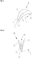
- Fig. 1 shows in a perspective view of a web unit 40 comprising two web plates 42, which are connected via cross plates 45.
- the web unit 40 extends along a longitudinal direction L (or along a circumferential direction of the brake drum) and forms respective functional regions 60 at their respective ends, one (rear) being spherical, in particular spherical, and the front rather cylindrical.
- L longitudinal direction
- the web unit 40 forms a circumferential arrangement surface 41, via which the arrangement or attachment to a pad, not shown here, for example via a welded joint.
- the great advantage of the web unit 40 becomes clear that in fact only one component has to be “traded”.
- FIG. 2 shows the off FIG. 1 known web unit 40 along the longitudinal direction L or in the circumferential direction.
- a center plane M is substantially symmetrical or axisymmetric configuration of Web unit 40.
- the connection of the two web plates 42 on the cross plate 45 is shown.
- the functional area 60 extends downwards.
- the sketched section AA is in FIG. 3 shown.
- Fig. 3 shows the section AA, as in FIG. 2 outlined.
- the course of the arrangement surface 41 as well as the lateral contour of the two functional areas 60 can be seen in particular. It can also be seen that a height of the web unit 40 decreases toward its ends.
- the sketched section BB is in FIG. 4 shown.
- the trapezoidal shape results from the position and orientation of the web plates 42 relative to the connecting plate 44.
- a width b40 of the web unit and a width b44 of the connecting plate 44 wherein an advantageous Ratio hereby in a range of about 1.0 to 2.0, preferably 1.3 to 1.7.
- Dashed lines indicate the orientation of a lining sheet.
- an angle ⁇ is measured, which in preferred embodiments is, for example, in a range of approximately 90 ° to 130 °, preferably 92 ° to 105 °.
- Fig. 5 shows the in FIG. 3 to be seen web unit folded down.
- the course of the web plates 42 which can be essentially referred to as convex, becomes clear.
- the web plates 42 form an angle ⁇ , which z. B. in a range of about 2 ° to 30 °, preferably 4 ° to 25 ° or 10 ° to 20 °.
- the width ratios of the web unit 40 wherein a maximum width b max in a central region of the web unit is about 100 mm to 120 mm, while a minimum width b min in a range of about 40 mm to 50 mm is clear. The minimum width is measured approximately in the area of the functional areas 60.
- Fig. 6 shows a brake shoe 10, comprising a pad plate 20, to which two web units 40 are attached via a welded joint.
- the two bridge units 40 are welded together along a weld joint 50 along a dividing plane T.
- the web units 40 include side web plates 42 and transverse plates 45.
- the web plates 42 are connected by connecting plates 44, which extend to the pad plate 20 such that the connecting plates 44 have a larger radius of curvature than the pad plate 20.
- the connecting plate 44 forms an elongated opening 46.
- the web units 40 each include a functional area 60, both of which are spherical or spherical.
- Fig. 7 shows a similar configuration of a brake shoe 10 as shown FIG. 6 known. The difference here is that only one web unit 40 is provided here. Moreover, here a right functional area 60 is cylindrical.
- Fig. 8 shows a cam member 80, which is the operation of two brake shoes 10, which are only partially shown here used. The introduction of force takes place at the corresponding functional areas 60 of the brake shoes 10 or the web unit 40.
- a friction-reducing layer 86 is indicated, which is arranged on the cam element 80 and which improves the friction behavior between the cam element 80 and the functional areas 60.
- Fig. 9 essentially shows the FIG. 8 known configuration, in which case a needle bearing 62 is arranged on a functional area 60 of a brake shoe 10. Again, the cam member 80 is provided with a friction-reducing layer 86.
- Fig. 10 shows the needle bearing 62 in a detailed view.
- a bearing cage 63 which can be rotatably attached to a functional area 60 of the web unit 40, can be seen.
- a corresponding axis of rotation D is indicated, via which ultimately the (rotatable) arrangement takes place at the corresponding functional area of the web unit.
- Fig. 11 shows the arrangement of a needle bearing 62 with its bearing cage 63 on a web unit 40 and its functional area 60. About a rotational axis D, a corresponding mobility is provided.
Landscapes
- Engineering & Computer Science (AREA)
- General Engineering & Computer Science (AREA)
- Mechanical Engineering (AREA)
- Braking Arrangements (AREA)
Abstract
Description
- Die vorliegende Erfindung betrifft eine Bremsbacke, insbesondere einer Trommelbremse für Nutzfahrzeuge, eine Stegeinheit für eine Bremsbacke sowie eine Trommelbremse.
- Trommelbremsen sind im Nutzfahrzeugsegment sowie für Anhänger immer noch der bevorzugte Bremsentyp. Der Grundaufbau besteht dabei aus einer sich drehenden Bremstrommel, an welcher von innen zwei beweglich gelagerte Bremsbacken durch eine entsprechende Vorrichtung angepresst werden, wodurch die Bremskraft erzeugt wird. Bekannte Bremsbacken bestehen meist aus mehreren Teilen, die z. B. durch Schweißen und Pressen zusammengefügt werden: dem Belagblech, zwei Stegen, welche rückseitig an dem Belagblech befestigt sind, und entsprechenden Lagerstellen oder Lagerschalen, welche der Lagerung der Bremsbacke dienen. Der Fertigungs- und Handlingaufwand bei der Herstellung der Bremsbacken ist entsprechend hoch. Außerdem entstehen beim Zusammenfügen aufgrund der relativ hohen Anzahl von Bauteilen schnell Ungenauigkeiten, insbesondere als Folge der sich addierenden Toleranzen.
- Es ist daher Aufgabe der vorliegenden Erfindung, eine Bremsbacke, eine Stegeinheit einer Bremsbacke sowie eine Trommelbremse anzugeben, welche schneller, einfacher und dabei noch genauer und kostengünstiger herzustellen sind.
- Diese Aufgabe wird durch eine Bremsbacke gemäß Anspruch 1, eine Stegeinheit gemäß Anspruch 12 sowie durch eine Trommelbremse gemäß Anspruch 14 gelöst. Weitere Vorteile und Merkmale ergeben sich aus den Unteransprüchen sowie der Beschreibung und den beigefügten Figuren.
- Erfindungsgemäß umfasst eine Bremsbacke, insbesondere einer Trommelbremse für Nutzfahrzeuge, ein Belagblech und eine Stegeinheit, wobei die Stegeinheit als einteiliger Körper mit zumindest zwei Stegblechen ausgebildet ist. Typischerweise umfasst die Trommelbremse eine Bremstrommel, an welche von innen zwei, z. B. auf einem Bremsträger bzw. einer Bremsankerplatte, beweglich gelagerte Bremsbacken durch eine entsprechende Vorrichtung angepresst werden. Die Lagerung der Bremsbacke sowie die Krafteinleitung erfolgt über die Stegbleche, welche vorteilhafterweise der ganzen Anordnung die nötige Steifigkeit verleihen. Das Anpressen der Bremsbacken kann direkt mechanisch über eine Nockenwelle, einen Spreizkeil oder über einen Radbremszylinder erfolgen. Zum Bereitstellen der eigentlichen Bremswirkung ist auf dem Belagblech der Bremsbacke ein entsprechender Bremsbelag angeordnet, insbesondere beispielsweise genietet. Im Stand der Technik sind rückseitig am Belagblech zwei voneinander unabhängige Flansche oder auch Stege angeschweißt. Diese müssen relativ zum Belagblech sowie zueinander exakt positioniert werden, da, wie bereits erwähnt, über die Stege oder Stegbleche die Lagerung der Bremsbacke sowie die Krafteinleitung erfolgt. Mit Vorteil weist nun die Bremsbacke die Stegeinheit auf, welche als einteiliger bzw. einstückiger Körper umfassend die zumindest zwei Stegbleche ausgebildet ist. Diese Konfiguration lässt Toleranzen entfallen, die durch das Zusammensetzen der einzelnen Bauteile entstehen würden. Da die Stegeinheit aus einem Stück besteht, erfordert die Koordinierung bei der Montage weniger Aufwand. Fertigungs- und Montageschritte können damit gegenüber dem Stand der Technik entfallen. Die Stegeinheit kann als Einheit rückseitig auf dem Belagblech form- und/oder kraft- und/oder stoffschlüssig befestigt werden. Bevorzugt ist sie z. B. angeschweißt. Vorteilhafterweise ist die Stegeinheit aus einem homogenen Material ausgebildet.
- Gemäß einer Ausführungsform ist die Stegeinheit z. B. ein Tiefziehteil, wobei die Stegeinheit und das Belagblech bevorzugt über die Schweißverbindung verbunden sind. Auch kann die Stegeinheit aus einer Vielzahl von, vorzugsweise zwei, tiefgezogenen Blechen ausgebildet sein, welche miteinander verklebt und/oder verschweißt sind. So kann die Stegeinheit einen sandwich-artigen Aufbau aufweisen. Alternativ kann die Stegeinheit auch durch Schmieden, Biegen, Dengeln, Hydroformen oder Drücken hergestellt werden. Die Stegeinheit kann auch gefaltet sein. Alternativ kann die Stegeinheit auch als einteilige Schweißkonstruktion ausgebildet sein, welche dann als eine Einheit am Belagblech befestigt wird. Der Begriff Einheit bzw. die Einteiligkeit ist insbesondere dahingehend zu verstehen, dass die Stegeinheit bevorzugt (durchgehend) aus einem homogenen Gefüge oder Material gebildet ist. Je nach Ausführungsform ist dabei aber nicht ausgeschlossen, dass dieses Gefüge ggf. durch z. B. eine Schweißnaht unterbrochen wird. Wichtig ist vielmehr, dass die Stegeinheit, wenn sie nicht am Belagträger angeordnet ist, ein (einziges) Bauteil ist, umfassend zumindest zwei Stegbleche, welche in der Regel entweder über ein Querblech oder über ein Verbindungsblech verbunden sind.
- Gemäß einer Ausführungsform weist die Stegeinheit zumindest ein Verbindungsblech auf, welches die zwei Stegflächen verbindet. Gemäß einer Ausführungsform ist das Verbindungsblech im Wesentlichen parallel zum Belagblech orientiert bzw. bildet dessen Orientierung nach. Zweckmäßigerweise ist das Verbindungsblech an einer dem Belagblech abgewandten Kante der Stegbleche angeordnet. Ein maximaler Abstand des Verbindungsblechs zu einer Rückseite des Belagblechs beträgt in bevorzugten Ausführungsformen etwa 40-100 mm, bevorzugt etwa 50-90 mm. Der Abstand ist dabei im Mittelbereich des Belagträgers am höchsten, da hier die höchsten Kräfte aufzunehmen sind. Zweckmäßigerweise ist der Abstand des Verbindungsblechs zur Rückseite des Belagträgers in der Mitte der Bremsbacke am höchsten und fällt entlang der Stegeinheit, also entlang einer Umfangsrichtung der Bremstrommel, zu beiden Seiten ab. Damit kann mit Vorteil eine Gewichtsreduktion erreicht werden. Der vorgenannte Abstand entspricht im Wesentlichen der Höhe der Stegbleche, welche im Folgenden noch erwähnt wird. Das Verbindungsblech oder die Verbindungsbleche erstrecken sich im Wesentlichen entlang der Umfangsrichtung. Quer dazu ist die Stegeinheit gemäß einer Ausführungsform durch zumindest ein Querblech verbunden, welches sozusagen ein Ende der Stegeinheit in Umfangsrichtung darstellt. Gemäß einer Ausführungsform ist die Stegeinheit damit vollumfänglich geschlossen. Stegbleche und Querbleche formen eine umlaufende Anordnungsfläche, über welche die Anordnung an der Rückseite des Belagblechs, also der dem Reibbelag abgewandten Seite, erfolgt. Diese geschlossene Struktur ist extrem steif und kann entsprechend dünnwandig und leicht ausgeführt werden. Grundsätzlich sei an dieser Stelle erwähnt, dass der Werkstoff der Stegeinheit, wie auch für das Belagblech, bevorzugt ein Stahlwerkstoff ist. Eine Wandstärke der Stegeinheit liegt in bevorzugten Ausführungsformen bei etwa 1-8 mm, besonders bevorzugt bei etwa 2-6 mm.
- Gemäß einer Ausführungsform weist das Verbindungsblech zumindest eine Öffnung oder eine Ausnehmung auf bzw. formt diese. Dies ermöglicht ebenfalls eine weitere Gewichtsreduktion und kann außerdem für eine Wärmeabfuhr aus der einteilig gebildeten Stegeinheit verwendet werden. Die Öffnung kann als Bohrung, insbesondere als runde oder kreisrunde Bohrung ausgebildet sind. Bevorzugt ist aber auch eine längliche Öffnung, welche sich zumindest abschnittsweise entlang der Umfangsrichtung erstreckt. Die Breite der Öffnung ist dabei derart bemessen, dass noch Teile des Verbindungsblechs stehen bleiben. Dies ermöglicht gerade in Längsrichtung/Umfangsrichtung eine hohe Steifigkeit bei geringem Materialeinsatz. Gemäß einer Ausführungsform liegt ein Verhältnis einer Breite des Verbindungsblechs zu einer Breite der Öffnung in einem Bereich von etwa 0,1-0,9, bevorzugt bei etwa 0,2-0,8. Das Verbindungsblech im Allgemeinen ermöglicht vorteilhafterweise eine Erhöhung der Steifigkeit der Stegeinheit sowie eine verbesserte Wärmeabfuhr wie auch Wärmeverteilung. So können über das Verbindungsblech von einem Stegblech zum anderen leicht Wärmeunterschiede und Temperaturspitzen ausgeglichen werden. Über die Anordnungen von Öffnungen/Ausnehmungen in dem oder den Verbindungsblechen oder ggf. auch in den Stegblechen selbst, kann die Temperaturverteilung individuell angepasst werden. Besonders zweckmäßig ist im Verbindungsblech durch zwei benachbart zueinander liegende Öffnung (bspw. runde Öffnung und Langloch) ein Stegbereich ausgebildet, welcher einen Eingriffsbereich zum Einhängen einer Rückzugsfeder bildet.
- Gemäß einer Ausführungsform verlaufen die Stegbleche bezogen auf eine Mittelebene des Belagblechs im Wesentlichen bogenförmig, insbesondere konvex. Die Mittelebene ist diejenige Ebene, die mittig und senkrecht zum Belagblech entlang dessen Längsrichtung bzw. entlang der Umfangsrichtung verläuft. In der Regel ist die Mittelebene auch die Symmetrieebene. Die Bogenform ist insbesondere in einer Draufsicht auf die Rückseite der Bremsbacke zu erkennen. Zweckmäßigerweise ist eine Breite der Stegeinheit in der Mitte also größer als an ihren jeweiligen Enden. Zweckmäßigerweise liegt ein Verhältnis einer minimalen Breite zu einer maximalen Breite bei etwa 0,05-0,8, bevorzugt bei etwa 0,08-0,7. Diese Konfiguration ermöglicht eine optimale Festigkeit bzw. Steifigkeit der Bremsbacke bei minimalem Materialeinsatz. Zudem wird durch den Verlauf der Stegbleche auf die Rückseite des Belagblechs die Wärmeabfuhr aus dem Belagblech bestmöglich bewerkstelligt. Gemäß einer Ausführungsform verlaufen die Stegbleche in der Draufsicht auch gerade, sind aber trotzdem so ausgerichtet, dass sie bezogen auf die Mittelebene schräg verlaufen. Ausgehend von den jeweiligen Enden der Stegeinheit beschreiben die Stegbleche also einen Winkel zu Mitte hin, welcher z. B. in einem Bereich von etwa 2°-30°, bevorzugt etwa 4°-25°, und besonders bevorzugt 10°-20° liegt. Zweckmäßigerweise ist die Stegeinheit bezogen auf die Mittelebene symmetrisch, insbesondere achsensymmetrisch, ausgebildet.
- Gemäß einer Ausführungsform sind die Stegbleche auch zu einer Mittelebene des Belagblechs hin geneigt. In Kombination mit dem Verbindungsblech ergibt sich also zweckmäßigerweise eine Trapezform, eine Geometrie welche den entstehenden Kräften äußerst gut entgegenwirkt. Ein Winkel des Stegblechs (außen an der Stegeinheit gemessen) relativ zur Rückseite des Belagblechs gemessen liegt gemäß einer Ausführungsform z. B. in einem Bereich von ca. 90°-130°, bevorzugt bei etwa 92°-105°. Insbesondere können die Stegbleche an ihren dem Belagblech zugewandten Seiten bzw. Kanten weiter vonenander beabstandet sein als bei ihren dem Belagblech abgewandten Seiten bzw. Kanten.
- Gemäß einer Ausführungsform ist die Stegeinheit derart ausgelegt, dass eine Steifigkeit der Stegeinheit zur Mitte der Bremsbacke hin zunimmt. Dabei bedeutet zur Mitte hin insbesondere "in Umfangsrichtung gesehen" zur Mitte hin. So ist beispielsweise eine Höhe der Stegbleche im mittleren Bereich größer als zu den entsprechenden Endbereichen hin, wo die Bremsbacke gelagert wird oder wo die Krafteinleitung erfolgt. Die Höhenabnahme kann stetig erfolgen oder auch gestuft bzw. in Schritten. Zweckmäßigerweise liegt eine minimale Höhe der Stegbleche, welche im Bereich der Funktionsbereiche am Rand gemessen wird, zu einer maximalen Höhe der Stegbleche in der Mitte in einem Bereich von 0,2 bis 0,8, bevorzugt in einem Bereich von 0,3-0,7. Dabei wird die Höhe der Stegbleche senkrecht zum Belagträger gemessen. Die gilt im Übrigen auch für den Abstand des oder der Verbindungsbleche.
- Gemäß einer Ausführungsform umfasst die Bremsbacke zwei Stegeinheiten, welche entlang einer Teilungsebene miteinander verbunden, insbesondere verschweißt, sind. Die Teilungsebene verläuft dabei im Wesentlichen quer zu einer Längsrichtung bzw. Umfangsrichtung der Bremstrommel bzw. der Bremsbacke. Insbesondere steht die Teilungsebene im Wesentlichen auch quer zu der Mittelebene (es ist aber auch ein Winkel ungleich 90° möglich). Eine derartige Konfiguration kann insbesondere im Hinblick auf die Fertigung der Stegeinheit vorteilhaft sein, da sich damit weitere Möglichkeiten ergeben, wie beispielsweise das Falten oder Drücken/Biegen/Dengeln aus einem Stück Blech.
- Gemäß einer Ausführungsform formt die Stegeinheit zumindest einen Funktionsbereich, insbesondere einen Lagerabschnitt, welcher insbesondere sphärisch oder zylindrisch ausgebildet ist. Daneben kann ein Funktionsbereich auch ein Krafteinleitungsbereich sein. Im Stand der Technik ist der Krafteinleitungsbereich beispielsweise über eine Nockenrolle gestaltet, welche an den Stegen (drehbar) befestigt ist. Mit Vorteil ist eben diese Funktion durch die zylindrische Ausgestaltung des Funktionsbereichs direkt und unmittelbar durch die Stegeinheit bereitgestellt. Die Lagerung der Bremsbacke erfolgt im Stand der Technik z. B. über eine Kugel, welche an den Stegen über eine entsprechende Lagerschale/Kugelschale befestigt ist. Mit Vorteil ist diese Funktion direkt und unmittelbar durch die sphärische Ausgestaltung des Funktionsbereichs bereitgestellt. Grundsätzlich ist die explizite Gestaltung des Funktionsbereichs - sphärisch, kugelförmig, zylindrisch oder ggf. auch eine andere Geometrie - nicht entscheidend. Wesentlich ist, dass die Stegeinheit selbst diese Geometrie oder Form ausbildet, diese also auch durch Tiefziehen, Schmieden, Biegen, Dengeln, Hydroformen, Drücken etc. hergestellt ist. Dabei können beide Funktionsbereiche gleich oder auch unterschiedlich ausgebildet sein. Der Funktionsbereich wird also bevorzugt zusammen mit der Stegeinheit ausgeformt und bildet mit dieser vorteilhafterweise eine Einheit. Alternativ kann der Lagerabschnitt auch als gesondertes Bauteil an der Stegeinheit form- und/oder kraftschlüssig bzw. stoffschlüssig befestigt bzw. z. B. angeschweißt werden.
- Gemäß einer Ausführungsform ist an dem Funktionsbereich oder Lagerabschnitt ein Nadellager angeordnet bzw. vorgesehen. Gemäß einer Ausführungsform weist das Nadellager einen entsprechenden Lagerkäfig auf, um gegenüber der Stegeinheit positioniert werden zu können und sich dem Verlauf einer Nockenkontur anpassen zu können. Der Lagerkäfig wiederum ist zweckmäßigerweise drehbar an dem Funktionsbereich der Stegeinheit befestigt oder angeordnet.
- Die Erfindung bezieht sich im Übrigen auch auf eine Stegeinheit, welche die vorgenannten Vorteile und Merkmale aufweist. Insbesondere ist eine Stegeinheit beansprucht, welche als einteiliger Körper umfassend zumindest zwei Stegbleche ausgebildet ist. Zweckmäßigerweise umfasst die Stegeinheit auch noch zumindest einen Funktionsbereich, welcher ebenfalls Teil des vorgenannten einteiligen Körpers ist.
- Die Erfindung bezieht sich auch auf eine Trommelbremse umfassend zumindest eine Bremsbacke nach einem der vorhergehenden Ansprüche, sowie ein Nockenelement zur Betätigung der zumindest einen Bremsbacke, wobei an einer Kontaktfläche des Nockenelements eine reibungsmindernde Schicht vorgesehen ist. Diese Schicht kann beispielsweise aus einem abriebfesten Kunststoffmaterial, einem verschleißfesten Gleitlack oder einer Teflonbeschichtung gefertigt sein. Die reibungsmindernde Schicht ist insbesondere auf den für die Stegeinheit verwendeten (Stahl-) Werkstoff abgestimmt, da die Stegeinheit ja direkt und unmittelbar bevorzugt auch den Funktionsbereich, z. B. den Lagerabschnitt und/oder den Krafteinleitungsbereich, ausbildet.
- Weitere Vorteile und Merkmale ergeben sich aus der nachfolgenden Beschreibung bevorzugter Ausführungsformen der erfindungsgemäßen Bremsbacke sowie der erfindungsgemäßen Trommelbremse mit Bezug auf die beigefügten Figuren. Einzelne Merkmale der einzelnen Ausführungsformen können dabei im Rahmen der Erfindung miteinander kombiniert werden.
- Es zeigen:
- Figur 1:
- eine Ausführungsform einer Stegeinheit in einer perspektivischen Darstellung;
- Figur 2:
- die aus
Figur 1 bekannte Stegeinheit entlang einer Längsrichtung/Umfangsrichtung gesehen; - Figur 3:
- den Schnitt A-A, wie in
Figur 2 skizziert; - Figur 4:
- den Schnitt B-B, wie in
Figur 3 skizziert; - Figur 5:
- eine Draufsicht auf die aus
Figur 1 bekannte Stegeinheit; - Figur 6:
- eine perspektivische Darstellung einer Ausführungsform einer Bremsbacke;
- Figur 7:
- eine weitere perspektivische Darstellung einer Ausführungsform einer Bremsbacke;
- Figur 8:
- eine Ausführungsform eines Nockenelements;
- Figur 9:
- eine weitere Ausführungsform eines Nockenelements, wobei die Bremsbacke mit Nadellagern versehen ist;
- Figur 10:
- eine Ausführungsform eines Nadellagers;
- Figur 11:
- eine Ausführungsform einer Stegeinheit mit einem daran angeordneten Nadellager.
-
Fig. 1 zeigt in einer perspektivischen Darstellung eine Stegeinheit 40 umfassend zwei Stegbleche 42, welche über Querbleche 45 verbunden sind. Die Stegeinheit 40 erstreckt sich entlang einer Längsrichtung L (bzw. entlang einer Umfangsrichtung der Bremstrommel) und formt an ihren jeweiligen Enden jeweils Funktionsbereiche 60 aus, wobei der eine (hintere) sphärisch ausgebildet ist, insbesondere kugelförmig, der vordere eher zylindrisch. Deutlich zu sehen ist die einteilige Ausgestaltung der Stegeinheit 40, umfassend die beiden Stegbleche 42, die Querbleche 45 und die Funktionsbereiche 60. Die Stegeinheit 40 bildet eine umlaufende Anordnungsfläche 41 aus, über welche die Anordnung bzw. Befestigung an einem hier nicht dargestellten Belagblech, beispielsweise über eine Schweißverbindung, erfolgt. Dabei wird der große Vorteil der Stegeinheit 40 deutlich, dass nämlich nur ein Bauteil "gehandelt" werden muss. Daneben zeigt sich deutlich die abnehmende Höhe der Stegbleche 42 hin zu den Funktionsbereichen 60. Die Höhe der Stegbleche 42 ist also in der Mitte der Stegeinheit 40 am höchsten und nimmt zu den Enden stetig bzw. kontinuierlich ab. -
Fig. 2 zeigt die ausFigur 1 bekannte Stegeinheit 40 entlang der Längsrichtung L bzw. in Umfangsrichtung gesehen. Zu sehen ist die in Bezug auf eine Mittelebene M im Wesentlichen symmetrische bzw. achsensymmetrische Ausgestaltung der Stegeinheit 40. Insbesondere ist in der hier dargestellten Ansicht die Verbindung der beiden Stegbleche 42 über das Querblech 45 dargestellt. Vom Querblech 45 weg erstreckt sich der Funktionsbereich 60 nach unten. Der skizzierte Schnitt A-A ist inFigur 3 dargestellt. -
Fig. 3 zeigt den Schnitt A-A, wie inFigur 2 skizziert. Zu sehen ist insbesondere der Verlauf der Anordnungsfläche 41 sowie die seitliche Kontur der beiden Funktionsbereiche 60. Erkennbar ist auch, das eine Höhe der Stegeinheit 40 zu Ihren Enden hin abnimmt. Der skizzierte Schnitt B-B ist inFigur 4 dargestellt. -
Fig. 4 zeigt insbesondere die im Wesentlichen trapezförmige Ausgestaltung des Querschnitts der Stegeinheit 40. Insbesondere ergibt sich die Trapezform durch die Lage und Orientierung der Stegbleche 42 relativ zum Verbindungsblech 44. Somit ergibt sich eine Breite b40 der Stegeinheit und eine Breite b44 des Verbindungsblechs 44, wobei ein vorteilhaftes Verhältnis hierbei in einem Bereich von etwa 1,0 bis 2,0, vorzugsweise 1,3 bis 1,7 liegt. Gestrichelt angedeutet ist die Orientierung eines Belagblechs. Zwischen dem Belagblech und dem Stegblech 42 bemisst sich ein Winkel α, welcher in bevorzugten Ausführungsformen beispielsweise in einem Bereich von ca. 90° bis 130°, vorzugsweise 92° bis 105° liegt. -
Fig. 5 zeigt die inFigur 3 zu sehende Stegeinheit nach unten geklappt. Deutlich wird hier insbesondere der Verlauf der Stegbleche 42, welcher im Wesentlichen als konvex bezeichnet werden kann. Hierbei schließen die Stegbleche 42 einen Winkel β ein, welcher z. B. in einem Bereich von etwa 2° bis 30°, vorzugsweise 4° bis 25° oder 10° bis 20° liegt. Deutlich werden auch die Breitenverhältnisse der Stegeinheit 40, wobei eine maximale Breite bmax in einem Mittelbereich der Stegeinheit bei etwa 100 mm bis 120 mm liegt, während eine minimale Breite bmin in einem Bereich von etwa 40 mm bis 50 mm liegt. Die minimale Breite bemisst sich dabei etwa im Bereich der Funktionsbereiche 60. -
Fig. 6 zeigt eine Bremsbacke 10, umfassend ein Belagblech 20, an welcher zwei Stegeinheiten 40 über eine Schweißverbindung befestigt sind. Die beiden Stegeinheiten 40 sind entlang einer Schweißverbindung 50 entlang einer Teilungsebene T miteinander verschweißt. Die Stegeinheiten 40 umfassen seitliche Stegbleche 42 sowie Querbleche 45. Überdies sind die Stegbleche 42 durch Verbindungsbleche 44 verbunden, welche sich derart zu dem Belagblech 20 erstrecken, dass die Verbindungsbleche 44 einen größeren Krümmungsradius als das Belagblech 20 aufweisen. Das Verbindungsblech 44 formt eine längliche Öffnung 46 aus. Die Stegeinheiten 40 umfassen jeweils einen Funktionsbereich 60, wobei hier beide sphärisch bzw. kugelförmig ausgebildet sind. -
Fig. 7 zeigt eine ähnliche Konfiguration einer Bremsbacke 10 wie ausFigur 6 bekannt. Der Unterschied liegt hier darin, dass hier nur eine Stegeinheit 40 vorgesehen ist. Überdies ist hier ein rechter Funktionsbereich 60 zylinderförmig ausgebildet. -
Fig. 8 zeigt ein Nockenelement 80, welches der Betätigung zweier Bremsbacken 10, welche hier nur ansatzweise dargestellt sind, dient. Die Krafteinleitung erfolgt an den entsprechenden Funktionsbereichen 60 der Bremsbacken 10 bzw. der Stegeinheit 40. Angedeutet ist eine reibungsmindernde Schicht 86, welche auf dem Nockenelement 80 angeordnet ist und welche das Reibverhalten zwischen dem Nockenelement 80 und den Funktionsbereichen 60 verbessert. -
Fig. 9 zeigt im Wesentlichen die ausFigur 8 bekannte Konfiguration, wobei hier ein Nadellager 62 an einem Funktionsbereich 60 einer Bremsbacke 10 angeordnet ist. Auch hier ist das Nockenelement 80 mit einer reibungsmindernden Schicht 86 versehen. -
Fig. 10 zeigt das Nadellager 62 in einer Detaildarstellung. Zu sehen ist hier insbesondere ein Lagerkäfig 63, welcher drehbar an einem Funktionsbereich 60 der Stegeinheit 40 befestigt werden kann. Angedeutet ist hierbei eine entsprechende Drehachse D, über welche letztendlich die (drehbare) Anordnung am entsprechenden Funktionsbereich der Stegeinheit erfolgt. -
Fig. 11 zeigt die Anordnung eines Nadellagers 62 mit seinem Lagerkäfig 63 an einer Stegeinheit 40 bzw. dessen Funktionsbereich 60. Um eine Drehachse D ist eine entsprechende Beweglichkeit bereitgestellt. -
- 10
- Bremsbacke
- 20
- Belagblech
- 40
- Stegeinheit
- b40
- Breite der Stegeinheit
- bmin
- minimale Breite (der Stegeinheit)
- bmax
- maximale Breite (der Stegeinheit)
- 41
- Anordnungsfläche
- 42
- Stegbleche
- 44
- Verbindungsblech
- 45
- Querblech
- 46
- Öffnung
- 50
- Schweißnaht
- 60
- Funktionsbereich, Lagerabschnitt, Krafteinleitungsbereich
- 62
- Nadellager
- 64
- Lagerkäfig
- 80
- Nockenelement
- 86
- reibungsmindernde Schicht
- M
- Mittelebene
- T
- Teilungsebene
- L
- Längsrichtung
- D
- Drehachse
- α, β
- Winkel
Claims (14)
- Bremsbacke (10), insbesondere einer Trommelbremse für Nutzfahrzeuge, umfassend ein Belagblech (20) und eine Stegeinheit (40),
wobei die Stegeinheit (40) als einteiliger Körper umfassend zumindest zwei Stegbleche (42) ausgebildet ist. - Bremsbacke (10) nach Anspruch 1,
wobei die Stegeinheit (40) ein Tiefziehteil ist, und
wobei die Stegeinheit (40) und das Belagblech (20) bevorzugt über eine Schweißverbindung verbunden sind. - Bremsbacke (10) nach einem der vorhergehenden Ansprüche,
wobei die Stegeinheit (40) ein Verbindungsblech (44) aufweist, welches die zwei Stegbleche (42) verbindet. - Bremsbacke (10) nach Anspruch 3,
wobei das Verbindungsblech (44) zumindest eine Öffnung aufweist. - Bremsbacke (10) nach einem der vorhergehenden Ansprüche,
wobei die Stegbleche (42) bezogen auf eine Mittelebene (M) des Belagblechs (20) im Wesentlichen bogenförmig verlaufen, insbesondere konvex. - Bremsbacke (10) nach einem der vorhergehenden Ansprüche,
wobei die Stegbleche (42) zu einer Mittelebene (M) des Belagblechs (20) hin geneigt sind. - Bremsbacke (10) nach einem der vorhergehenden Ansprüche,
wobei die Stegeinheit (40) derart ausgelegt ist, dass eine Steifigkeit der Stegeinheit (40) zur Mitte der Bremsbacke (20) hin zunimmt. - Bremsbacke (10) nach einem der vorhergehenden Ansprüche,
wobei die Stegeinheit (40) im Querschnitt zumindest abschnittsweise eine Trapezform aufweist. - Bremsbacke (10) nach einem der vorhergehenden Ansprüche,
umfassend zwei Stegeinheiten (40) welche entlang einer Teilungsebene (T) miteinander verbunden, insbesondere verschweißt sind. - Bremsbacke (10) nach einem der vorhergehenden Ansprüche,
wobei die Stegeinheit (40) zumindest einen Funktionsbereich, insbesondere einen Lagerabschnitt (60) beispielsweise zur Anordnung eines Nadellagers (62), formt, welcher insbesondere sphärisch oder zylindrisch ausgebildet ist. - Bremsbacke (10) nach Anspruch 10,
wobei an dem Funktionsbereich (60) ein Nadellager (62) angeordnet ist. - Stegeinheit einer Bremsbacke für Trommelbremsen, insbesondere für Nutzfahrzeuge, welche als einteiliger Körper ausgebildet ist und zwei Stegbleche (42) aufweist.
- Stegeinheit nach Anspruch 12,
weiterhin umfassend einen Funktionsbereich, der vorzugsweise Teil des einteiligen Körpers ist. - Trommelbremse, umfassend
zumindest eine Bremsbacke (10) nach einem der vorhergehenden Ansprüche, und
ein Nockenelement (80) zur Betätigung der zumindest einen Bremsbacke (10),
wobei eine Kontaktfläche des Nockenelements (80) eine reibungsmindernde Schicht (86) aufweist.
Applications Claiming Priority (1)
| Application Number | Priority Date | Filing Date | Title |
|---|---|---|---|
| DE102015118233.5A DE102015118233B4 (de) | 2015-10-26 | 2015-10-26 | Bremsbacke |
Publications (1)
| Publication Number | Publication Date |
|---|---|
| EP3163110A1 true EP3163110A1 (de) | 2017-05-03 |
Family
ID=57189943
Family Applications (1)
| Application Number | Title | Priority Date | Filing Date |
|---|---|---|---|
| EP16195308.8A Withdrawn EP3163110A1 (de) | 2015-10-26 | 2016-10-24 | Bremsbacke |
Country Status (3)
| Country | Link |
|---|---|
| US (1) | US10253830B2 (de) |
| EP (1) | EP3163110A1 (de) |
| DE (1) | DE102015118233B4 (de) |
Families Citing this family (5)
| Publication number | Priority date | Publication date | Assignee | Title |
|---|---|---|---|---|
| USD822563S1 (en) * | 2014-07-17 | 2018-07-10 | Dennis Michael Nosworthy | Disc brake caliper bracket |
| DE102015112712B4 (de) * | 2015-08-03 | 2017-05-11 | Paul Brüser Gmbh | Bremsbacke |
| CN109404441B (zh) * | 2018-12-31 | 2021-01-15 | 河北百龙汽车配件股份有限公司 | 一种防脱刹车蹄 |
| CN114082880B (zh) * | 2021-06-09 | 2025-03-21 | 衡水永信制动材料有限公司 | 一种可用于商用汽车刹车片的新型钢背 |
| DE102023207999A1 (de) | 2023-08-22 | 2025-02-27 | Robert Bosch Gesellschaft mit beschränkter Haftung | Elektromechanische Trommelbremse |
Citations (5)
| Publication number | Priority date | Publication date | Assignee | Title |
|---|---|---|---|---|
| US1794348A (en) * | 1928-03-14 | 1931-02-24 | Gen Motors Res Corp | Pressed-metal brake shoe |
| US1914997A (en) * | 1928-10-06 | 1933-06-20 | Bendix Brake Co | Manufacture of brake shoes |
| US1943836A (en) * | 1930-05-28 | 1934-01-16 | Bendix Brake Co | Brake operator |
| US1957635A (en) * | 1928-12-24 | 1934-05-08 | Edwin R Evans | Brake shoe construction |
| FR879050A (fr) * | 1942-02-04 | 1943-02-11 | Nouveau segment, ou mâchoire, de frein ou d'embrayage |
Family Cites Families (22)
| Publication number | Priority date | Publication date | Assignee | Title |
|---|---|---|---|---|
| US1537911A (en) * | 1923-12-31 | 1925-05-12 | Otto B Wunschow | Brake shoe |
| US1656607A (en) * | 1926-04-26 | 1928-01-17 | Studebaker Corp | Brake |
| US1636003A (en) | 1926-05-22 | 1927-07-19 | Bendix Brake Co | Brake shoe |
| US1652485A (en) | 1926-11-29 | 1927-12-13 | Bendix Brake Co | Brake shoe |
| US1934460A (en) * | 1927-12-15 | 1933-11-07 | Bendix Aviat Corp | Brake shoe |
| US1898310A (en) | 1930-08-02 | 1933-02-21 | Bendix Brake Co | Brake shoe |
| US1937997A (en) * | 1930-09-15 | 1933-12-05 | Gen Motors Corp | Welded brake shoe |
| US1865823A (en) * | 1931-04-13 | 1932-07-05 | Gen Motors Res Corp | Composite brake shoe |
| US2148257A (en) | 1936-08-12 | 1939-02-21 | Bendix Prod Corp | Method of making brake shoes |
| US2852106A (en) * | 1955-10-10 | 1958-09-16 | Jr Carl Cull | Double action cam and roller brake operator |
| US3677374A (en) | 1969-06-25 | 1972-07-18 | Girling Ltd | Cam actuated drum brake |
| US3891069A (en) * | 1969-11-21 | 1975-06-24 | Girling Ltd | Brake shoes |
| DE2148257A1 (de) | 1971-09-28 | 1973-04-05 | Bosch Gmbh Robert | Fluessigkeitsfilter |
| US4932505A (en) * | 1985-12-23 | 1990-06-12 | Echlin Inc. | Roller body for brake shoe actuator cam |
| JPH11270598A (ja) * | 1998-03-19 | 1999-10-05 | Nissan Diesel Motor Co Ltd | ドラムブレーキのブレーキシュー |
| US6581728B2 (en) * | 2001-02-08 | 2003-06-24 | Volvo Trucks North America, Inc. | Brake shoe proximity sensor |
| US7677369B2 (en) * | 2005-11-30 | 2010-03-16 | Gm Global Technology Operations, Inc. | Hydroformed drum brake shoe assembly for vehicles and method of making same |
| DE102010031889A1 (de) * | 2010-07-21 | 2012-01-26 | Jancer Vermögensverwaltungs Ug (Haftungsbeschränkt) & Co. Kg | Verfahren zum Herstellen eines Bremsbelagträgers |
| DE102013201111B4 (de) * | 2013-01-24 | 2015-11-05 | Saf-Holland Gmbh | Bremsbacke für eine Trommelbremse |
| DE102013201108B4 (de) * | 2013-01-24 | 2016-01-07 | Saf-Holland Gmbh | Bremsbacke für eine Trommelbremse |
| US20140246283A1 (en) * | 2013-03-04 | 2014-09-04 | Arvinmeritor Technology, Llc | Brake pad assembly having a flange |
| US20150167765A1 (en) * | 2013-12-12 | 2015-06-18 | Bendix Commercial Vehicle Systems Llc | Tri-cam brake assembly |
-
2015
- 2015-10-26 DE DE102015118233.5A patent/DE102015118233B4/de active Active
-
2016
- 2016-10-24 EP EP16195308.8A patent/EP3163110A1/de not_active Withdrawn
- 2016-10-26 US US15/334,480 patent/US10253830B2/en active Active
Patent Citations (5)
| Publication number | Priority date | Publication date | Assignee | Title |
|---|---|---|---|---|
| US1794348A (en) * | 1928-03-14 | 1931-02-24 | Gen Motors Res Corp | Pressed-metal brake shoe |
| US1914997A (en) * | 1928-10-06 | 1933-06-20 | Bendix Brake Co | Manufacture of brake shoes |
| US1957635A (en) * | 1928-12-24 | 1934-05-08 | Edwin R Evans | Brake shoe construction |
| US1943836A (en) * | 1930-05-28 | 1934-01-16 | Bendix Brake Co | Brake operator |
| FR879050A (fr) * | 1942-02-04 | 1943-02-11 | Nouveau segment, ou mâchoire, de frein ou d'embrayage |
Also Published As
| Publication number | Publication date |
|---|---|
| US20170114844A1 (en) | 2017-04-27 |
| US10253830B2 (en) | 2019-04-09 |
| DE102015118233B4 (de) | 2019-01-03 |
| DE102015118233A1 (de) | 2017-04-27 |
Similar Documents
| Publication | Publication Date | Title |
|---|---|---|
| DE102015118233B4 (de) | Bremsbacke | |
| DE1625756B2 (de) | Teilbelagscheibenbremse fuer kraftfahrzeuge | |
| DE102018114396B4 (de) | Scheibenbremse mit einer Rückstelleinrichtung und Bremsbelagsatz einer solchen Scheibenbremse | |
| DE102012103017A1 (de) | Lagerung eines eine teilzylindrische Außenfläche aufweisenden Drehhebels gegenüber einem Druckstück | |
| EP3237773B1 (de) | Scheibenbremse für ein nutzfahrzeug | |
| EP2895760B1 (de) | Pneumatisch oder elektromechanisch betätigbare scheibenbremse | |
| DE102014113370A1 (de) | Scheibenbremse für ein Nutzfahrzeug | |
| EP3310594B1 (de) | Strebe für eine radaufhängung | |
| DE202017100162U1 (de) | Lenker in Schalenbauweise für eine Radaufhängung eines Fahrzeugs | |
| EP2266817B1 (de) | Radlagerung für Fahrzeugachsen | |
| DE102013108065A1 (de) | Elastomerlager | |
| DE202007005313U1 (de) | Scheibenbremse und Lagerblock für eine Scheibenbremse | |
| EP2994325B1 (de) | Achsanbindung | |
| EP3027926B1 (de) | Scheibenbremse, insbesondere für nutzfahrzeuge, sowie bremsbelag einer solchen scheibenbremse | |
| EP3170678B1 (de) | Radnabe | |
| DE102016109184B4 (de) | Haltebock | |
| WO2007082520A2 (de) | Scheibenbremse | |
| DE102014108500B4 (de) | Zuspanneinrichtung für eine Scheibenbremse | |
| EP4217622B1 (de) | Zuspanneinrichtung einer scheibenbremse | |
| EP2772372B1 (de) | Fahrwerk für ein nutzfahrzeug und achskörper | |
| DE102016218412A1 (de) | Schwenkhebelanordnung für eine Scheibenbremse mit Flügelabschnitten | |
| DE102014115766B4 (de) | Scheibenbremse für ein Nutzfahrzeug | |
| EP2986459B1 (de) | Längslenker | |
| EP2428375B1 (de) | Verfahren zur Herstellung eines Stabilisators sowie Stabilisator | |
| EP2428695B1 (de) | Im Bremssattel einer Scheibenbremse angeordnete Zuspanneinrichtung |
Legal Events
| Date | Code | Title | Description |
|---|---|---|---|
| PUAI | Public reference made under article 153(3) epc to a published international application that has entered the european phase |
Free format text: ORIGINAL CODE: 0009012 |
|
| STAA | Information on the status of an ep patent application or granted ep patent |
Free format text: STATUS: THE APPLICATION HAS BEEN PUBLISHED |
|
| AK | Designated contracting states |
Kind code of ref document: A1 Designated state(s): AL AT BE BG CH CY CZ DE DK EE ES FI FR GB GR HR HU IE IS IT LI LT LU LV MC MK MT NL NO PL PT RO RS SE SI SK SM TR |
|
| AX | Request for extension of the european patent |
Extension state: BA ME |
|
| STAA | Information on the status of an ep patent application or granted ep patent |
Free format text: STATUS: REQUEST FOR EXAMINATION WAS MADE |
|
| 17P | Request for examination filed |
Effective date: 20170522 |
|
| RBV | Designated contracting states (corrected) |
Designated state(s): AL AT BE BG CH CY CZ DE DK EE ES FI FR GB GR HR HU IE IS IT LI LT LU LV MC MK MT NL NO PL PT RO RS SE SI SK SM TR |
|
| STAA | Information on the status of an ep patent application or granted ep patent |
Free format text: STATUS: EXAMINATION IS IN PROGRESS |
|
| 17Q | First examination report despatched |
Effective date: 20200603 |
|
| STAA | Information on the status of an ep patent application or granted ep patent |
Free format text: STATUS: THE APPLICATION IS DEEMED TO BE WITHDRAWN |
|
| 18D | Application deemed to be withdrawn |
Effective date: 20201014 |