EP3162687A2 - Vehicle - Google Patents
Vehicle Download PDFInfo
- Publication number
- EP3162687A2 EP3162687A2 EP16191392.6A EP16191392A EP3162687A2 EP 3162687 A2 EP3162687 A2 EP 3162687A2 EP 16191392 A EP16191392 A EP 16191392A EP 3162687 A2 EP3162687 A2 EP 3162687A2
- Authority
- EP
- European Patent Office
- Prior art keywords
- body frame
- vehicle
- cross member
- axis
- lower cross
- Prior art date
- Legal status (The legal status is an assumption and is not a legal conclusion. Google has not performed a legal analysis and makes no representation as to the accuracy of the status listed.)
- Granted
Links
- 230000035939 shock Effects 0.000 claims abstract description 139
- 239000006096 absorbing agent Substances 0.000 claims abstract description 112
- 239000000725 suspension Substances 0.000 claims description 143
- 230000007246 mechanism Effects 0.000 claims description 66
- 230000005540 biological transmission Effects 0.000 claims description 62
- 230000036544 posture Effects 0.000 claims description 16
- 230000002093 peripheral effect Effects 0.000 claims description 14
- 238000006073 displacement reaction Methods 0.000 claims description 13
- 230000008859 change Effects 0.000 claims description 3
- 230000014509 gene expression Effects 0.000 description 21
- 230000000694 effects Effects 0.000 description 15
- 238000011144 upstream manufacturing Methods 0.000 description 15
- 230000009467 reduction Effects 0.000 description 6
- 230000009471 action Effects 0.000 description 2
- 230000015572 biosynthetic process Effects 0.000 description 2
- 230000004048 modification Effects 0.000 description 2
- 238000012986 modification Methods 0.000 description 2
- 230000002195 synergetic effect Effects 0.000 description 2
- 230000004075 alteration Effects 0.000 description 1
- 239000000470 constituent Substances 0.000 description 1
- 238000010276 construction Methods 0.000 description 1
- 238000013016 damping Methods 0.000 description 1
- 238000012217 deletion Methods 0.000 description 1
- 230000037430 deletion Effects 0.000 description 1
- 239000002828 fuel tank Substances 0.000 description 1
- 230000006872 improvement Effects 0.000 description 1
- 230000004044 response Effects 0.000 description 1
Images


Classifications
-
- B—PERFORMING OPERATIONS; TRANSPORTING
- B62—LAND VEHICLES FOR TRAVELLING OTHERWISE THAN ON RAILS
- B62K—CYCLES; CYCLE FRAMES; CYCLE STEERING DEVICES; RIDER-OPERATED TERMINAL CONTROLS SPECIALLY ADAPTED FOR CYCLES; CYCLE AXLE SUSPENSIONS; CYCLE SIDE-CARS, FORECARS, OR THE LIKE
- B62K5/00—Cycles with handlebars, equipped with three or more main road wheels
- B62K5/10—Cycles with handlebars, equipped with three or more main road wheels with means for inwardly inclining the vehicle body on bends
-
- B—PERFORMING OPERATIONS; TRANSPORTING
- B60—VEHICLES IN GENERAL
- B60G—VEHICLE SUSPENSION ARRANGEMENTS
- B60G13/00—Resilient suspensions characterised by arrangement, location or type of vibration dampers
- B60G13/001—Arrangements for attachment of dampers
- B60G13/005—Arrangements for attachment of dampers characterised by the mounting on the axle or suspension arm of the damper unit
-
- B—PERFORMING OPERATIONS; TRANSPORTING
- B62—LAND VEHICLES FOR TRAVELLING OTHERWISE THAN ON RAILS
- B62K—CYCLES; CYCLE FRAMES; CYCLE STEERING DEVICES; RIDER-OPERATED TERMINAL CONTROLS SPECIALLY ADAPTED FOR CYCLES; CYCLE AXLE SUSPENSIONS; CYCLE SIDE-CARS, FORECARS, OR THE LIKE
- B62K21/00—Steering devices
- B62K21/18—Connections between forks and handlebars or handlebar stems
-
- B—PERFORMING OPERATIONS; TRANSPORTING
- B62—LAND VEHICLES FOR TRAVELLING OTHERWISE THAN ON RAILS
- B62K—CYCLES; CYCLE FRAMES; CYCLE STEERING DEVICES; RIDER-OPERATED TERMINAL CONTROLS SPECIALLY ADAPTED FOR CYCLES; CYCLE AXLE SUSPENSIONS; CYCLE SIDE-CARS, FORECARS, OR THE LIKE
- B62K25/00—Axle suspensions
- B62K25/04—Axle suspensions for mounting axles resiliently on cycle frame or fork
- B62K25/06—Axle suspensions for mounting axles resiliently on cycle frame or fork with telescopic fork, e.g. including auxiliary rocking arms
- B62K25/08—Axle suspensions for mounting axles resiliently on cycle frame or fork with telescopic fork, e.g. including auxiliary rocking arms for front wheel
-
- B—PERFORMING OPERATIONS; TRANSPORTING
- B62—LAND VEHICLES FOR TRAVELLING OTHERWISE THAN ON RAILS
- B62K—CYCLES; CYCLE FRAMES; CYCLE STEERING DEVICES; RIDER-OPERATED TERMINAL CONTROLS SPECIALLY ADAPTED FOR CYCLES; CYCLE AXLE SUSPENSIONS; CYCLE SIDE-CARS, FORECARS, OR THE LIKE
- B62K5/00—Cycles with handlebars, equipped with three or more main road wheels
- B62K5/02—Tricycles
- B62K5/027—Motorcycles with three wheels
-
- B—PERFORMING OPERATIONS; TRANSPORTING
- B62—LAND VEHICLES FOR TRAVELLING OTHERWISE THAN ON RAILS
- B62K—CYCLES; CYCLE FRAMES; CYCLE STEERING DEVICES; RIDER-OPERATED TERMINAL CONTROLS SPECIALLY ADAPTED FOR CYCLES; CYCLE AXLE SUSPENSIONS; CYCLE SIDE-CARS, FORECARS, OR THE LIKE
- B62K5/00—Cycles with handlebars, equipped with three or more main road wheels
- B62K5/02—Tricycles
- B62K5/05—Tricycles characterised by a single rear wheel
-
- B—PERFORMING OPERATIONS; TRANSPORTING
- B62—LAND VEHICLES FOR TRAVELLING OTHERWISE THAN ON RAILS
- B62K—CYCLES; CYCLE FRAMES; CYCLE STEERING DEVICES; RIDER-OPERATED TERMINAL CONTROLS SPECIALLY ADAPTED FOR CYCLES; CYCLE AXLE SUSPENSIONS; CYCLE SIDE-CARS, FORECARS, OR THE LIKE
- B62K5/00—Cycles with handlebars, equipped with three or more main road wheels
- B62K5/08—Cycles with handlebars, equipped with three or more main road wheels with steering devices acting on two or more wheels
-
- B—PERFORMING OPERATIONS; TRANSPORTING
- B60—VEHICLES IN GENERAL
- B60G—VEHICLE SUSPENSION ARRANGEMENTS
- B60G2300/00—Indexing codes relating to the type of vehicle
- B60G2300/12—Cycles; Motorcycles
- B60G2300/122—Trikes
-
- B—PERFORMING OPERATIONS; TRANSPORTING
- B62—LAND VEHICLES FOR TRAVELLING OTHERWISE THAN ON RAILS
- B62K—CYCLES; CYCLE FRAMES; CYCLE STEERING DEVICES; RIDER-OPERATED TERMINAL CONTROLS SPECIALLY ADAPTED FOR CYCLES; CYCLE AXLE SUSPENSIONS; CYCLE SIDE-CARS, FORECARS, OR THE LIKE
- B62K5/00—Cycles with handlebars, equipped with three or more main road wheels
- B62K2005/001—Suspension details for cycles with three or more main road wheels
Definitions
- the present disclosure relates to a vehicle equipped with a leanable body frame and two front wheels.
- a vehicle described in, for example, Patent Literature 1 comprises a body frame that leans to the left or right of the vehicle when the vehicle turns left or right and two front wheels that are arranged side by side in a left-right direction of the body frame.
- This type of vehicle is a vehicle which is able to turn with its body frame leaning from a vertical direction. More specifically, the body frame leans to the right of the vehicle when the vehicle turns to the right, while when the vehicle turns to the left, the body frame leans to the left of the vehicle.
- a distance between the two front wheels which are arranged side by side in the left-right direction of the body frame is very short, compared with a general four-wheeled vehicle. Consequently, this type of vehicle is compact in size in relation to the left-right direction of the body frame.
- the vehicle described in Patent Literature 1 comprises a so-called parallelogram type link mechanism.
- the parallelogram type link mechanism can be disposed above the two front wheels.
- a link mechanism that is known as a double wishbone type link mechanism is disposed between the two front wheels in the left-right direction of the body frame. Accordingly, the vehicle equipped with the parallelogram type link mechanism is more compact in size in relation to the left-right direction of the body frame than the vehicle equipped with the double wishbone type link mechanism.
- the parallelogram type link mechanism comprises an upper cross member, a lower cross member, a left side member and a right side member.
- the upper cross member, the lower cross member, the left side member and the right side member are connected so that the upper cross member and the lower cross member keep postures parallel to each other and the left side member and the right side member keep postures parallel to each other.
- the upper cross member and the lower cross member are supported on the body frame so as to turn about axes that extend in a front-rear direction of the body frame.
- the left side member is supported at a left portion of the upper cross member and a left portion of the lower cross member so as to turn abut axes that extend in the front-rear direction of the body frame.
- the right side member is supported at a right portion of the upper cross member and a right portion of the lower cross member so as to turn abut axes that extend in the front-rear direction of the body frame.
- the upper cross member, the lower cross member, the left side member and the right side member turn individually about the axes that extend in the front-rear direction of the body frame. Accordingly, movable ranges of the upper cross member, the lower cross member, the left side member and the right side member when the parallelogram type link mechanism operates are relatively small in relation to a front-rear direction of the vehicle.
- the vehicle described in Patent Literature 1 comprises a telescopic suspension device.
- the telescopic suspension device includes a left suspension device and a right suspension device.
- the left suspension device supports one (a left front wheel) of the two front wheels at a lower portion thereof and is supported on the left side member at an upper portion thereof.
- the left suspension device attenuates an upward displacement of the left front wheel in an up-down direction of the body frame relative to the upper portion thereof.
- the right suspension device supports the other (a right front wheel) of the two front wheels at a lower portion thereof and is supported on the right side member at an upper portion thereof.
- the right suspension device attenuates an upward displacement of the right front wheel in the up-down direction of the body frame relative to the upper portion thereof.
- the telescopic suspension device comprises an inner tube and an outer tube.
- the inner tube and the outer tube are displaced relatively along a telescopic axis that extends in the up-down direction of the body frame. Accordingly, movable ranges of the inner tube and the outer tube when the telescopic suspension device operates are relatively small in the front-rear direction of the vehicle.
- the vehicle comprises the parallelogram type link mechanism and the telescopic suspension device is compact in size in the front-rear direction.
- a maximum displacement amount (hereinafter, referred to as a stroke) of the suspension device is increased.
- the stroke can be increased accordingly.
- the vehicle is increased in size in the up-down direction.
- a maximum leaning angle (hereinafter, referred to as a maximum banking angle) of the body frame is increased.
- a maximum banking angle can be increased by increasing the space defined between the left member and the right member in the left-right direction of the body frame.
- the space defined between the left member and the right member in the left-right direction of the body frame is expanded, however, the space defined between the left side member that supports the left suspension device and the right side member that supports the right suspension device in the left-right direction of the body frame is expanded.
- This increases the size of the vehicle in the left-right direction.
- distances from the turning centers of the upper cross member and the lower cross member about which they turn relative to the body frame to the left side member and the right side member become long. Accordingly, the movable range of the link mechanism becomes wide not only in the left-right direction but also in the up-down direction of the body frame. Consequently, the vehide is also increased in size in the up-down direction.
- a vehicle comprising:
- the configuration is known in which a recess portion (a relief portion) that the left shock absorber and the right shock absorber can enter is formed in the lower cross member. According to this configuration, the enlargement in size of the vehicle in the up-down direction can be suppressed while avoiding the interference of the left shock absorber and the right shock absorber with the lower cross member when the body frame leans. However, since the displacement amount of the left shock absorber and the right shock absorber towards the lower cross member increases as the maximum banking angle increases, a deeper recess portion needs to be formed. This will be true when attempting to increase the stroke, too.
- the dimension of the lower cross member in the up-down direction of the body frame needs to be increased. As a result, it becomes difficult to suppress the enlargement in size of the vehicle in the up-down direction.
- the inventors conceived that the goal described above can be achieved by devising the arrangement of the left shock absorber and the right shock absorber in place of the conventional countermeasures in which the shape of the lower cross member is devised.
- a portion of the lower cross member where the left shock absorber and the right shock absorber could interfere with the lower cross member is a portion that is positioned between the left steering axis and the right steering axis when the vehicle in which the body frame is standing upright is viewed from the front in the front-rear direction of the body frame.
- the portion is a portion that would be relatively much related to the rigidity of the lower cross member. In other words, it can be said that the portion is a portion having a relatively low degree of freedom in selecting a shape therefor from the viewpoint of ensuring
- a portion of the lower cross member where the left shock absorber could interfere with the lower cross member is a portion that is positioned between the left steering axis and the left end of the lower cross member when the vehicle in which the body frame is standing upright is viewed from the front in the front-rear direction of the body frame.
- a portion of the lower cross member where the right shock absorber could interfere with the lower cross member is a portion that is positioned between the right steering axis and the right end of the lower cross member when the vehicle in which the body frame is standing upright is viewed from the front in the front-rear direction of the body frame.
- These portions are portions that would be relatively less related to the rigidity of the lower cross member. In other words, it can be said that these portions are portions having a relatively high degree of freedom in selecting shapes therefor from the viewpoint of ensuring the rigidity of the lower cross member.
- the inventors conceived that it would be advantageous to dispose the left shock absorber and the right shock absorber in the position where the left shock absorber and the right shock absorber could interfere with the portions that would be relatively less related to the rigidity of the lower cross member and which have relatively high degree of freedom in selecting the shapes of the portions from the viewpoint of ensuring the rigidity of the lower cross member.
- the left rear telescopic element that serves as the left shock absorber is disposed so that the left telescopic axis is positioned on the left of the left steering axis in the left-right direction of the body frame when the vehicle in which the body frame is standing upright is viewed from the front in the front-rear direction of the body frame.
- the right rear telescopic element that serves as the right shock absorber is disposed so that the right telescopic axis is positioned on the right of the right steering axis in the left-right direction of the body frame.
- the left shock absorber moves away from the portion that is positioned between the left steering axis and the left end of the lower cross member as the vehicle leans to the left.
- the right shock absorber moves towards the portion that is positions between the right steering axis and the right end of the lower cross member. Since the portion positioned on the right of the right steering axis has the high degree of freedom in utilizing the space, however, the shape and arrangement of the right suspension device can easily be so selected as to avoid the interference of both members. Accordingly, it becomes easy to shorten the distance between the right shock absorber and the lower cross member in the up-down direction of the body frame.
- the right shock absorber moves away from the portion that is positioned between the right steering axis and the right end of the lower cross member as the vehicle leans to the right.
- the left shock absorber moves towards the portion that is positions between the left steering axis and the left end of the lower cross member. Since the portion positioned on the left of the left steering axis has the high degree of freedom in utilizing the space, however, the shape and arrangement of the left suspension device can easily be so selected as to avoid the interference of both members. Accordingly, it becomes easy to shorten the distance between the left shock absorber and the lower cross member in the up-down direction of the body frame.
- a possible reduction in rigidity of the lower cross member can be kept minimum.
- a recess portion where part of the right suspension device can enter is formed in the portion that is positioned between the right steering axis and the right end of the lower cross member in order to avoid the interference of the right suspension device with the lower cross member, a possible reduction in rigidity of the lower cross member can be kept minimum.
- the above vehicle may be configured as follows.
- the lower cross member is positioned in a position that is axisymmetric with a left edge of the left suspension device relative to the left steering axis when the vehicle in which the body frame is caused to lean to the left with a maximum angle.
- the lower cross member is positioned in a position that is axisymmetric with a right edge of the right suspension device relative to the right steering axis when the vehicle in which the body frame is caused to lean to the right with a maximum angle.
- the axisymmetric position corresponds to a location where the right end of the left suspension device is positioned when the vehicle is caused to lean to the left with the maximum angle at which the left shock absorber is disposed on the right of the left steering axis in the left-right direction of the body frame.
- this case means that the lower cross member interferes with the left suspension device.
- the left suspension device that supports the left shock absorber needs to be disposed below the left suspension device, and the enlargement in size of the vehicle in the up-down direction of the body frame cannot be avoided.
- the left end portion of the lower cross member and the left shock absorber move way from each other.
- the axisymmetric position corresponds to a location where a left end of the right suspension device is positioned when the vehicle is caused to lean to the right with the maximum angle at which the right shock absorber is disposed on the left of the right steering axis in the left-right direction of the body frame.
- this case means that the lower cross member interferes with the right suspension device.
- the right suspension device that supports the right shock absorber needs to be disposed below the right suspension device, and the enlargement in size of the vehicle in the up-down direction of the body frame cannot be avoided.
- the right end portion of the lower cross member and the right shock absorber move way from each other.
- the portion positioned directly on the left of the left steering axis has the high degree of freedom in utilizing the space, it is easy to avoid the interference of the left end portion of the lower cross member with the left shock absorbing device. Consequently, it becomes easy to reduce the distance between the lower cross member and the right shock absorber in the up-down direction of the body frame.
- the above vehicle may be configured as follows.
- a left portion of the lower cross member is supported on a lower portion of the left side member such that the left portion of the lower cross member is turnable about a lower left connecting axis extending in the front-rear direction of the body frame.
- a right portion of the lower cross member is supported on a lower portion of the right side member such that the right portion of the lower cross member is turnable about a lower right connecting axis extending in the front-rear direction of the body frame.
- the lower cross member has a left recess portion at a left peripheral edge portion that is positioned on the left of the lower left connecting axis in the left-right direction of the body frame.
- the lower cross member has a right recess portion at a right peripheral edge portion that is positioned on the right of the lower right connecting axis in the left-right direction of the body frame.
- a part of the right suspension device is able to enter the right recess portion at least when the body frame is caused to lean from an upright state thereof to the left of the vehicle with a maximum angle.
- a part of the left suspension device is able to enter the left recess portion at least when the body frame is caused to lean from the upright state thereof to the right of the vehicle with a maximum angle.
- the left recess portion is formed to avoid the interference of the lower cross member with part of the left suspension device
- the right recess portion is formed to avoid the interference of the lower cross member with part of the right suspension device
- the above vehicle may be configured as follows.
- An upper end of the left recess portion and an upper end of the right recess portion in the up-down direction of the body frame is positioned above a straight line connecting the lower left connecting axis and the lower right connecting axis in the up-down direction of the body frame.
- the left recess portion is formed on the left peripheral edge portion of the lower cross member, and the right recess portion is formed on the right peripheral edge portion of the lower cross member. Accordingly, although the depth over which the left turn-restricting member and the right turn-restricting member enter is increased by setting the positions of the upper end of the left recess portion and the upper end of the right recess portion in the way described above, the influence that would reduce the rigidity of the lower cross member can be suppressed. Consequently, since large contribution to the second advantageous effect and the third advantageous effect can be obtained, the enlargement in size of the vehicle in the up-down direction can be suppressed even though the maximum banking angle and the stroke of the suspension devices are increased.
- the above vehicle may be configured so as to comprise:
- the above vehide may be configured as follows.
- the part of the left suspension device in the left recess portion is movable within the left recess portion in accordance with the turn of the left suspension device about the left steering axis.
- the left recess portion is configured such that a movable amount of the part of the left suspension device within the left recess portion is reduced as a leaning angle of the body frame to the right of the vehicle increases.
- the part of the right suspension device in the right recess portion is movable within the right recess portion in accordance with the turn of the right suspension device about the right steering axis.
- the right recess portion is configured such that a movable amount of the part of the right suspension device within the right recess portion is reduced as a leaning angle of the body frame to the left of the vehicle increases.
- the mechanism that restricts the turning angle of the steering member according to the leaning angle of the body frame is provided by making use of the portion where the degree of freedom in selecting the shape is relatively high from the viewpoint of ensuring the rigidity of the lower cross member.
- the mechanism does not have to be provided in the location positioned between the left steering axis and the right steering axis of the lower cross member, that is, the portion that is involved relatively deeply in ensuring the rigidity of the lower cross member. Consequently, even though the maximum banking angle and the stroke of the suspension devices are increased, not only can the enlargement in size of the vehicle in the up-down direction be restricted, but also a countermeasure to enhance the rigidity of the lower cross member can easily be taken.
- the above vehicle may be configured as follows.
- the lower cross member comprises:
- the left recess portion is defined by the left connecting member.
- the right recess portion is defined by the right connecting member.
- the left recess portion having the desired shape can easily be formed by the left connecting member that is individual from the front element and the rear element.
- the right recess portion having the desired shape can easily be formed by the right connecting member that is individual from the front element and the rear element. Consequently, even though the maximum banking angle and the stroke of the suspension devices are increased, not only can the enlargement in size of the vehicle in the up-down direction be restricted, but also the mechanism that restricts the turning angle of the steering member according to the leaning angle of the body frame can easily be formed.
- the above vehicle may be configured as follows.
- a left portion of the lower cross member is supported on a lower portion of the left side member such that the left portion of the lower cross member is turnable about a lower left connecting axis extending in the front-rear direction of the body frame.
- a right portion of the lower cross member is supported on a lower portion of the right side member such that the right portion of the lower cross member is turnable about a lower right connecting axis extending in the front-rear direction of the body frame.
- An upper edge of the lower cross member has a portion positioned above a lower edge of the upper cross member in a vertical direction when the body frame is caused to lean from an upright state thereof to the left or the right of the vehicle with a maximum leaning angle, and viewed from a direction following the lower left connecting axis and the lower right connecting axis.
- the enlargement in size of the link mechanism in relation to the up-down direction of the body frame can be suppressed. Consequently, even though the maximum banking angle and the stroke of the suspension devices are increased, the enlargement in size of the vehicle in the up-down direction can be further suppressed.
- the above vehicle may be configured as follows.
- a left portion of the lower cross member is supported on a lower portion of the left side member such that the left portion of the lower cross member is turnable about a lower left connecting axis extending in the front-rear direction of the body frame.
- a right portion of the lower cross member is supported on a lower portion of the right side member such that the right portion of the lower cross member is turnable about a lower right connecting axis extending in the front-rear direction of the body frame.
- a turn angle of the lower cross member about the lower left connecting axis and the lower right connecting axis is smaller than the maximum leaning angle.
- the movable range of the link mechanism in the up-down direction of the body frame can be reduced. Consequently, even though the maximum banking angle and the stroke of the suspension devices are increased, the enlargement in size of the vehicle in the up-down direction can be further suppressed.
- the above vehicle may be configured as follows.
- the left front wheel is disposed on the right of the left shock absorber in the left-right direction of the body frame.
- the right front wheel is disposed on the left of the right shock absorber in the left-right direction of the body frame.
- the left front wheel and the right front wheel are disposed between the left shock absorber and the right shock absorber. According to this configuration, even though the maximum banking angle and the stroke of the suspension devices are increased, not only can the enlargement in size of the vehicle in the up-down direction be suppressed, but also the enlargement in size of the vehicle in the left-right direction can be suppressed.
- the above vehicle may be configured as follows.
- the left front wheel is disposed on the right of the left turn-restricting portion in the left-right direction of the body frame.
- the right front wheel is disposed on the left of the right turn-restricting portion in the left-right direction of the body frame.
- the left front wheel and the right front wheel are disposed between the left shock absorber, the left turn-restricting portion, the right shock absorber and the right turn-restricting portion. According to this configuration, even though the maximum banking angle and the stroke of the suspension devices are increased, not only can the enlargement in size of the vehicle in the up-down direction be suppressed, but also the enlargement in size of the vehicle in the left-right direction can be further suppressed.
- the above vehicle may be configured to comprise:
- the above vehicle may be configured as follows.
- the steering force transmission mechanism comprises:
- At least one of a front end of the left shock absorber and a front end of the left turn-restricting portion is positioned ahead of a rear end of the connecting portion in the front-rear direction of the body frame when the steering member is turned clockwise viewed from a rider with a maximum angle.
- At least one of a front end of the right shock absorber and a front end of the right turn-restricting portion is positioned ahead of the rear end of the connecting portion in the front-rear direction of the body frame when the steering member is turned counterclockwise viewed from the rider with a maximum angle.
- the above vehicle may be configured as follows.
- a left portion of the lower cross member is supported on a lower portion of the left side member such that the left portion of the lower cross member is turnable about a lower left connecting axis extending in the front-rear direction of the body frame.
- a right portion of the lower cross member is supported on a lower portion of the right side member such that the right portion of the lower cross member is turnable about a lower right connecting axis extending in the front-rear direction of the body frame.
- a lower edge of the lower cross member that is positioned between the lower left connecting axis and the lower right connecting axis is positioned below a straight line connecting the lower left connecting axis and the lower right connecting axis in the up-down direction of the body frame when the vehicle in which the body frame is standing upright is viewed from a direction following the lower left connecting axis and the lower right connecting axis.
- an arrow F denotes a front or forward direction of a vehicle.
- An arrow B denotes a back/rear or backward/rearward direction of the vehicle.
- An arrow U denotes an up or upward direction of the vehicle.
- An arrow D denotes a down or downward direction of the vehicle.
- An arrow R denotes a right or rightward direction of the vehicle.
- An arrow L denotes a left or leftward direction of the vehicle.
- an arrow FF denotes a front or forward direction of the body frame.
- An arrow FB denotes a back/rear or backward/rearward of the body frame.
- An arrow FU denotes an up or upward direction of the body frame.
- An arrow FD denotes a down or downward direction of the body frame.
- An arrow FR denotes a right or rightward direction of the body frame.
- An arrow FL denotes a left or leftward direction of the body frame.
- a "front-rear direction of the body frame,” a “left-right direction of the body frame” and an “up-down direction of the body frame” mean a front-rear direction, a left-right direction and an up-down direction based on the body frame when viewed from a rider who rides the vehicle.
- a side of or sideways of the body frame means directly on the right or left in the left-right direction of the body frame.
- an expression "extending in the front-rear direction of the vehicle body frame” includes a fact that it extends while being inclined in relation to the front-rear direction of the vehicle body frame and means that it extends in a direction closer to the front-rear direction of the vehicle body frame than the left-right direction and up-down direction of the vehicle body frame.
- an expression "extending in the left-right direction of the vehicle body frame” includes a fact that it extends while being inclined in relation to the left-right direction of the vehicle body frame and means that it extends in a direction closer to the left-right direction of the vehicle body frame than the front-rear direction and up-down direction of the vehicle body frame.
- an expression "extending in the up-down direction of the vehicle body frame” includes a fact that it extends while being inclined in relation to the up-down direction of the vehicle body frame and means that it extends in a direction closer to the up-down direction of the vehicle body frame than the left-right direction and front-rear direction of the vehicle body frame.
- an expression reading the "vehicle is standing upright or in an upright state” or the "body frame is standing upright or in the upright state” means a state in which the vehicle is not steered at all and the up-down direction of the body frame coincides with the vertical direction.
- the directions based on the vehicle coincide with the directions based on the body frame.
- the left-right direction of the vehicle does not coincide with the left-right direction of the body frame.
- the up-down direction of the vehicle does not coincide with the up-down direction of the body frame.
- the front-rear direction of the vehicle coincides with the front-rear direction of the body frame.
- an expression reading "directly on the left of a member A in the left-right direction of the body frame” denotes a space through which the member A passes when the member A is translated to the left in the left-right direction of the body frame.
- An expression reading "directly on the right of the member A” is also defined in the same way.
- an expression reading "on the left of the member A in the left-right direction of the body frame” includes not only the space through which the member A passes when the member A is translated to the left in the left-right direction of the body frame but also a space which expands from the space in directions which are at right angles to the left-right direction of the body frame.
- An expression reading "on the right of the member A” is also defined in the same way.
- an expression reading "directly above the member A in the up-down direction of the body frame” denotes a space through which the member A passes when the member A is translated upwards in the up-down direction of the body frame.
- An expression reading "directly below the member A” is also defined in the same way.
- an expression reading "above the member A in the up-down direction of the body frame” includes not only the space through which the member A passes when the member A is translated upwards in the up-down direction of the body frame but also a space which expands from the space in directions which are at right angles to the up-down direction of the body frame.
- An expression reading "below the member A” is also defined in the same way.
- an expression reading "directly ahead of the member A in the front-rear direction of the body frame” denotes a space through which the member A passes when the member A is translated to the front in the front-rear direction of the body frame.
- An expression reading "directly behind the member A” is also defined in the same way.
- an expression reading "ahead of the member A in the front-rear direction of the body frame” includes not only the space through which the member A passes when the member A is translated to the front in the front-rear direction of the body frame but also a space which expands from the space in directions which are at right angles to the front-rear direction of the body frame.
- An expression reading "behind the member A” is also defined in the same way.
- rotation, rotating or rotated means that a member is displaced at an angle of 360 degrees or more about an axis thereof.
- turn, turning or turned means that a member is displaced at an angle less than 360 degrees about an axis thereof.
- the vehicle 1 comprises a vehicle main body 2, two front wheels 3, a rear wheel 4, a link mechanism 5 and a steering member 6.
- the vehicle 1 is a vehicle that comprises a leanable body frame and the two front wheels 3 arranged side by side in the left-right direction of the body frame.
- the vehicle main body 2 comprises a body frame 21, a body cover 22, a seat 23, an engine unit 24, and a rear arm 25.
- Fig. 1 the body frame 21 is in the upright state.
- the following description to be made while referring to Fig. 1 is based on the premise that the body frame 21 is in the upright state.
- Fig. 1 is a left side view resulting when the whole of the vehicle 1 is viewed from the left in the left-right direction of the body frame 21.
- Fig. 2 is a view resulting when a front part of the vehicle 1 is viewed from the left in the left-right direction of the body frame 21.
- the body frame 21 is in the upright state.
- the following description to be made while referring to Fig. 2 is based on the premise that the body frame 21 is in the upright state.
- the body frame 21 comprises a head pipe 211, a link supporting portion 212 and a main frame 213.
- the head pipe 211 supports the steering member 6.
- the link supporting portion 212 supports the link mechanism 5.
- the main frame 213 supports the seat 23, the engine unit 24 and the rear arm 25.
- the rear arm 25 is disposed directly behind the main frame 213 in the front-rear direction of the body frame 21.
- the rear arm 25 extends in the front-rear direction of the body frame 21.
- a front end portion of the rear arm 25 is supported by the main frame 213 and the engine unit 24 and is allowed to turn about an axis that extends in the left-to-rear direction of the body frame 21.
- a rear end portion of the rear arm 25 supports the rear wheel 4.
- the body cover 22 is a body part that covers at least part of a group of constituent parts that make up the vehicle 1.
- the body cover 22 includes a front cover 221, a pair of left and right front fenders 222 and a rear front fender 223.
- the front cover 221 is disposed directly ahead of the seat 23 in the front-rear direction of the body frame 21.
- the front cover 221 covers the link mechanism 5, the steering member 6 and at least part of a steering force transmission mechanism 9.
- the front cover 221 is disposed so as not to be movable relative to the body frame 21.
- the front cover 221 is omitted from illustration.
- At least portions of the pair of left and right front fenders 222 are individually disposed directly below the front cover 221. At least portions of the pair of left and right front fenders 222 are disposed directly above the pair of left and right front wheels 3, respectively.
- At least part of the rear wheel 4 is disposed below the seat 23 in the up-down direction of the body frame 21. At least part of the rear wheel 4 is disposed directly below the rear front fender 223 in the up-down direction of the body frame 21.
- the vehicle 1 is a vehicle on which a rider mounts in a posture of straddling the body frame 21. Namely, when riding the vehicle 1, part of the body frame 21, which is disposed ahead of the seat 23 on which the rider sits in the front-rear direction of the body frame 21, is disposed between the legs of the rider. The rider rides on the vehicle 1 in a posture of holding the main frame 213 or the front cover 221 that is positioned ahead of the seat 23 in the front-rear direction of the body frame 21 by the legs therebetween.
- the engine unit 24 When viewing the vehicle 1 from the left-right direction of the body frame 21, the engine unit 24 is disposed ahead of a front end of the rear wheel 4 in the front-rear direction of the body frame 21.
- the engine unit 24 is disposed so as not to be movable relative to the body frame 21.
- the engine unit 24 is disposed so as not to be movable relative to the main frame 213.
- the engine 24 produces power for driving the vehicle 1.
- the driving force so produced is transmitted to the rear wheel 4.
- the head pipe 211 is disposed at a front portion of the vehicle 1.
- an upper portion of the head pipe 211 is disposed behind a lower portion of the head pipe 211 in the front-rear direction of the body frame 21.
- the steering member 6 comprises a handlebar 61 and an upstream steering shaft 62.
- the upstream steering shaft 62 extends downwards from a central portion of the handlebar 61 in the left-right direction.
- the upstream steering shaft 62 is supported on the head pipe 211 so as to turn about a rear intermediate steering axis SIB.
- the link supporting portion 212 is disposed directly ahead of the head pipe 211 in the front-rear direction of the body frame 21.
- an upper portion of the link supporting portion 212 is disposed behind a lower portion of the link supporting portion 212 in the front-rear direction of the body frame 21.
- Fig. 3 is a front view of the front part of the vehicle 1 resulting when viewed from the front in the front-rear direction of the body frame 21.
- the body frame 21 is in the upright state.
- the following description to be made while referring to Fig. 3 is based on the premise that the body frame 21 is in the upright state.
- the front cover 221 is omitted from illustration.
- the two front wheels 3 include a left front wheel 31 and a right front wheel 32.
- the left front wheel 31 is disposed on the left of the head pipe 211 and the link supporting portion 212 which make up part of the body frame 21 in the left-right direction of the body frame 21.
- the right front wheel 32 is disposed on the right of the head pipe 211 and the link supporting portion 212 which make up part of the body frame 21 in the left-right direction of the body frame 21.
- the left front wheel 31 and the right front wheel 32 are arranged side by side in the left-right direction of the body frame 21.
- the link mechanism 5 adopts a four parallel joint link system (also referred to as a parallelogram link).
- the link mechanism 5 is disposed above the left front wheel 31 and the right front wheel 32 in the up-down direction of the body frame 21.
- the link mechanism 5 comprises an upper cross member 51, a lower cross member 52, a left side member 53 and a right side member 54.
- the link mechanism 5 is not interlocked with the turning of the upstream steering shaft 62 about the rear intermediate steering axis SIB which occurs in association with the operation of the handlebar 61. Namely, the link mechanism 5 does not turn about the rear intermediate steering axis SIB relative to the body frame 21.
- the link supporting portion 212 has an upper intermediate connecting portion 212a. An intermediate portion of the upper cross member 51 is supported on the link supporting portion 212 via the upper intermediate connecting portion 212a.
- the upper cross member 51 is able to turn relative to the link supporting portion 212 about an upper intermediate connecting axis CUI that passes the upper intermediate connecting portion 212a and extends in the front-rear direction of the body frame 21.
- the link supporting portion 212 has a lower intermediate connecting portion 212b. An intermediate portion of the lower cross member 52 is supported on the link supporting portion 212 via the lower intermediate connecting portion 212b.
- the lower cross member 52 is able to turn relative to the link supporting portion 212 about a lower intermediate connecting axis CDI that passes the lower intermediate connecting portion 212b and extends in the front-rear direction of the body frame 21.
- the left side member 53 has an upper left connecting portion 53a.
- a left end portion of the upper cross member 51 is connected to the left side member 53 via the upper left connecting portion 53a.
- the upper cross member 51 is able to turn relative to the left side member 53 about an upper left connecting axis CUL that passes the upper left connecting 53a and which extends in the front-rear direction of the body frame 21.
- the right side member 54 has an upper right connecting portion 54a.
- a right end portion of the upper cross member 51 is connected to the right side member 54 via the upper right connecting portion 54a.
- the upper cross member 51 is able to turn relative to the right side member 54 about an upper right connecting axis CUR that passes the upper right connecting portion 54a and which extends in the front-rear direction of the body frame 21.
- the left side member 53 has a lower left connecting portion 53b.
- a left end portion of the lower cross member 52 is connected to the left side member 53 via the lower left connecting portion 53b.
- the lower cross member 52 is able to turn relative to the left side member 53 about a lower left connecting axis CDL that passes the lower left connecting 53b and which extends in the front-rear direction of the body frame 21.
- the right side member 54 has a lower right connecting portion 54b.
- a right end portion of the lower cross member 52 is connected to the right side member 54 via the lower right connecting portion 54b.
- the lower cross member 52 is able to turn relative to the right side member 54 about a lower right connecting axis CDR that passes the lower right connecting portion 54b and which extends in the front-rear direction of the body frame 21.
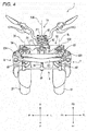
- Fig. 4 is a plan view of the front part of the vehicle 1 when viewed from the above in the up-down direction of the body frame 21.
- the body frame 21 is in the upright state.
- the following description to be made while referring to Fig. 4 is based on the premise that the body frame 21 is in the upright state.
- the front cover 221 is omitted from illustration.
- the upper cross member 51 is disposed ahead of the link supporting portion 212 in the front-rear direction of the body frame 21.
- the upper cross member 51 is a plate member that extends in the left-right direction of the body frame 21 without being curved in the front-rear direction of the body frame 21.
- the lower cross member 52 is disposed below the upper cross member 51 in the up-down direction of the body frame 21.
- the lower cross member 52 comprises a front element 521 and a rear element 522.
- the front element 521 is disposed ahead of the link supporting portion 212, the left side member 53 and the right side member 54 in the front-rear direction of the body frame 21.
- the rear element 522 is disposed behind the link supporting portion 212, the left side member 53 and the right side member 54 in the front-rear direction of the body frame 21.
- the front element 521 and the rear element 522 extend in the left-right direction of the body frame 21 without being curved in the front-rear direction of the body frame 21.
- the lower cross member 52 comprises a left connecting member 523 and a right connecting member 524.
- the left connecting member 523 connects a left end portion of the front element 521 and a left end portion of the rear element 522 together.
- the right connecting member 524 connects a right end portion of the front element 521 and a right end portion of the rear element 522.
- the left side member 53 is disposed directly on the left of the link supporting portion 212 in the left-right direction of the body frame 21.
- the left side member 53 is disposed above the left front wheel 31 in the up-down direction of the body frame 21.
- the left side member 53 extends in a direction in which the link supporting portion 212 extends.
- An upper portion of the left side member 53 is disposed behind a lower portion thereof in the front-rear direction of the body frame 21.
- the right side member 54 is disposed directly on the right of the link supporting portion 212 in the left-right direction of the body frame 21.
- the right side member 54 is disposed above the right front wheel 32 in the up-down direction of the body frame 21.
- the right side member 54 extends in the direction in which the link supporting portion 212 extends.
- An upper portion of the right side member 54 is disposed behind a lower portion thereof in the front-rear direction of the body frame 21.
- the upper cross member 51, the lower cross member 52, the left side member 53 and the right side member 54 are supported on the link supporting portion 212 so that the upper cross member 51 and the lower cross member 52 keep their postures that are parallel to each other and the left side member 53 and the right side member 54 keep their postures that are parallel to each other.
- the vehicle 1 comprises a left suspension device 7.
- the left suspension device 7 comprises a left bracket 71 and a left shock absorbing device 72.
- the left bracket 71 comprises a left turning member, not shown, that is provided at an upper portion thereof.
- the left turning member is disposed in an interior of the left side member 53 and extends in the same orientation as the direction in which the left side member 53 extends.
- the left turning member is able to turn about a left steering axis SL relative to the left side member 53.
- the left bracket 71 is connected to the left side member 53 so as to turn about the left steering axis SL.
- the left steering axis SL extends in the direction in which the left side member 53 extends.
- the left steering axis SL extends parallel to the rear intermediate steering axis SIB of the upstream steering shaft 62 in the up-down direction of the body frame 21.
- the left steering axis SL extends parallel to the rear intermediate steering axis SIB of the upstream steering shaft 62 in the up-down direction of the body frame 21.
- the left shock absorbing device 72 is a so-called telescopic shock absorbing mechanism.
- the left shock absorbing device 72 is configured so as to attenuate or absorb a displacement of the left front wheel 31 towards the link mechanism 5 in the up-down direction of the body frame 21.
- the left shock absorbing device 72 comprises a left front telescopic element 721, a left rear telescopic element 722, a left upper connecting member 723, a left lower connecting member 714 and a left axle 725.
- the left front telescopic element 721 comprises a left front outer tube 721a (an example of a left guide portion) and a left front inner tube 721 b (an example of a left guided portion).
- An outer diameter of the left front outer tube 721a is greater than an outer diameter of the left front inner tube 721 b.
- the left front outer tube 721 a is supported by the left bracket 71.
- the left front inner tube 721 b is connected to the left front outer tube 721 a so as to slide along a left telescopic axis EL.
- the left rear telescopic element 722 comprises a left rear outer tube 722a (an example of a left outer portion) and a left rear inner tube 722b (an example of a left inner portion).
- An outer diameter of the left rear outer tube 722a is greater than an outer diameter of the left rear inner tube 722b.
- the left rear outer tube 722a is disposed directly behind the left front outer tube 721 a in the front-rear direction of the body frame 21.
- the left rear outer tube 722a is supported by the left bracket 71.
- the left rear inner tube 722b is disposed directly behind the left front inner tube 721 b in the front-rear direction of the body frame 21.
- the left rear inner tube 722b is connected to the left rear outer tube 722a so as to slide along the left telescopic axis EL.
- the left upper connecting member 723 connects the left front outer tube 721a and the left rear outer tube 722a together.
- the left lower connecting member 724 connects the left front inner tube 721 b and the left rear inner tube 722b together.
- One end (a left end) of the left axle 725 is supported on the left front inner tube 721 b and the left rear inner tube 722b via the left lower connecting member 724.
- the other end (a right end) of the left axle 725 supports the left front wheel 31.
- the left shock absorbing device 72 is configured so as to attenuate or absorb a displacement of the left front wheel 31 towards the link mechanism 5 in the up-down direction of the body frame 21.
- the left rear telescopic element 722 is configured so as to serve as a left shock absorber.
- the left front telescopic element 721, the left upper connecting member 723 and the left lower connecting member 724 serve as a left turn-restricting portion and restrict the relative turning between the left rear outer tube 722a and the left rear inner tube 722b.
- the vehicle 1 comprises a right suspension device 8.
- the right suspension device 8 comprises a right bracket 81 and a right shock absorbing device 82.
- the configuration of the right suspension device 8 is symmetrical with the left suspension device 7 when the vehicle 1 is viewed from the left in the left-right direction of the body frame 21.
- the right suspension device 8 is not illustrated separately, and only reference numerals for the right suspension device 8 will be shown in Fig. 2 .
- the right bracket 81 comprises a right turning member, not shown, at an upper portion thereof.
- the right turning member is disposed in an interior of the right side member 54 and extends in the same orientation as the direction in which the right side member 54 extends.
- the right turning member is able to turn about a right steering axis SR relative to the right side member 54.
- the right bracket 81 is connected to the right side member 54 so as to turn about the right steering axis SR.
- the right steering axis SR extends in the direction in which the right side member 54 extends.
- the right steering axis SR extends parallel to the rear intermediate steering axis SIB of the upstream steering shaft 62 in the up-down direction of the body frame 21.
- the right steering axis SR extends parallel to the rear intermediate steering axis SIB of the upstream steering shaft 62 in the up-down direction of the body frame 21.
- the right shock absorbing device 82 is a so-called telescopic shock absorbing mechanism. As shown in Fig. 2 , the right shock absorbing device 82 comprises a right front telescopic element 821, a right rear telescopic element 822, a right upper connecting member 823, a right lower connecting member 824 and a right axle 825.
- the right front telescopic element 821 comprises a right front outer tube 821a (an example of a right guide portion) and a right front inner tube 821b (an example of a right guided portion).
- An outer diameter of the right front outer tube 821 a is greater than an outer diameter of the right front inner tube 821 b.
- the right front outer tube 821 a is supported by the right bracket 81.
- the right front inner tube 821b is connected to the right front outer tube 821a so as to slide along a right telescopic axis ER.
- the right rear telescopic element 822 comprises a right rear outer tube 822a (an example of a right outer portion) and a right rear inner tube 822b (an example of a right inner portion).
- An outer diameter of the right rear outer tube 822a is greater than an outer diameter of the right rear inner tube 822b.
- the right rear outer tube 822a is disposed directly behind the right front outer tube 821 a in the front-rear direction of the body frame 21.
- the right rear outer tube 822a is supported by the right bracket 81.
- the right rear inner tube 822b is disposed directly behind the right front inner tube 821b in the front-rear direction of the body frame 21.
- the right rear inner tube 822b is connected to the right rear outer tube 822a so as to slide along the right telescopic axis ER.
- the right upper connecting member 823 connects the right front outer tube 821a and the right rear outer tube 822a together.
- the right lower connecting member 824 connects the right front inner tube 821 b and the right rear inner tube 822b together.
- One end (a right end) of the right axle 825 is supported on the right front inner tube 821 b and the right rear inner tube 822b via the right lower connecting member 824.
- the other end (a left end) of the right axle 825 supports the right front wheel 32.
- the right shock absorbing device 82 is configured so as to attenuate or absorb a displacement of the right front wheel 32 towards the link mechanism 5 in the up-down direction of the body frame 21.
- the right rear telescopic element 822 is configured so as to serve as a right shock absorber.
- the right front telescopic element 821, the right upper connecting member 823 and the right lower connecting member 824 serve as a right turn-restricting portion and restrict the relative turning between the right rear outer tube 822a and the right rear inner tube 822b.
- the vehicle 1 comprises a steering force transmission mechanism 9.
- the steering force transmission mechanism 9 comprises a downstream steering shaft 91, a connecting device 92, an intermediate transmission plate 93, a left transmission plate 94, a right transmission plate 95, an intermediate joint 96, a left joint 97, a right joint 98 and a tie-rod 99.
- the downstream steering shaft 91 is supported on the link supporting portion 212 so as to turn about a front intermediate steering axis SIF.
- the front intermediate steering axis SIF extends parallel to the rear intermediate steering axis SIB about which the upstream steering shaft 62 turns.
- the connecting device 92 connects the upstream steering shaft 62 and the downstream steering shaft 91 together.
- the connecting device 92 is configured so as to be displaced in association with the turning of the upstream steering shaft 62.
- the downstream steering shaft 91 is configured so as to turn in association with the displacement of the connecting device 92.
- the connecting device 92 is configured so as to transmit a turning operation of the upstream steering shaft 62 to the downstream steering shaft 91.
- the intermediate transmission plate 93 (an example of an intermediate turning portion) is connected to a lower portion of the downstream steering shaft 91.
- the intermediate transmission plate 93 is not able to turn relative to the downstream steering shaft 91.
- the intermediate transmission plate 93 is able to turn about the front intermediate steering axis SIF relative to the link supporting portion 212.
- the left transmission plate 94 (an example of a left turning portion) is disposed directly on the left of the intermediate transmission plate 93 in the left-right direction of the body frame 21.
- the left transmission plate 94 is connected to a lower portion of the left bracket 71.
- the left transmission plate 94 is not able to turn relative to the left bracket 71.
- the left transmission plate 94 is able to turn about the left steering axis SL relative to the left side member 53.
- the right transmission plate 95 (an example of a right turning portion) is disposed directly on the right of the intermediate transmission plate 93 in the left-right direction of the body frame 21.
- the right transmission plate 95 is connected to a lower portion of the right bracket 81.
- the right transmission plate 95 is not able to turn relative to the right bracket 81.
- the right transmission plate 95 is able to turn about the right steering axis SR relative to the right side member 54.
- the intermediate joint 96 is connected to a front portion of the intermediate transmission plate 93 via a shaft portion that extends in the up-down direction of the body frame 21.
- the intermediate transmission plate 93 and the intermediate joint 96 are allowed to turn relative to each other about this shaft portion.
- the left joint 97 is disposed on the left of the intermediate joint 96 in the left-right direction of the body frame 21.
- the left joint 97 is connected to a front portion of the left transmission plate 94 via a shaft portion that extends in the up-down direction of the body frame 21.
- the left transmission plate 94 and the left joint 97 are allowed to turn relative to each other about this shaft portion.
- the right joint 98 is disposed on the right of the intermediate joint 96 in the left-right direction of the body frame 21.
- the right joint 98 is connected to a front portion of the right transmission plate 95 via a shaft portion that extends in the up-down direction of the body frame.
- the right transmission plate 95 and the right joint 98 are allowed to turn relative to each other about this shaft portion.
- a shaft portion that extends in the front-rear direction of the body frame 21 is provided at a front portion of the intermediate joint 96.
- a shaft portion that extends in the front-rear direction of the body frame 21 is provided at a front portion of the left joint 97.
- a shaft portion that extends in the front-rear direction of the body frame 21 is provided at a front portion of the right joint 98.
- the tie-rod 99 (an example of a connecting portion) extends in the left-right direction of the body frame 21.
- the tie-rod 99 is connected to the intermediate joint 96, the left joint 97 and the right joint 98 via those shaft portions.
- the tie-rod 99 and the intermediate joint 96 is able to turn relative to each other about the shaft portion that is provided at the front portion of the intermediate joint 96.
- the tie-rod 99 and the left joint 97 is able to turn relative to each other about the shaft portion that is provided at the front portion of the left joint 97.
- the tie-rod 99 and the right joint 98 is able to turn relative to each other about the shaft portion that is provided at the front portion of the right joint 98.
- the left transmission plate 94 is connected to the intermediate transmission plate 93 via the left joint 97, the tie-rod 99, and the intermediate joint 96.
- the right transmission plate 95 is connected to the intermediate transmission plate 93 via the right joint 98, the tie-rod 99 and the intermediate joint 96.
- the left transmission plate 94 and the right transmission plate 95 are connected to each other via the left joint 97, the tie-rod 99 and the right joint 98.
- the tie-rod 99 connects the intermediate transmission plate 93 to the left transmission plate 94 and the right transmission plate 95.
- FIG. 5 is a plan view of the front part of the vehicle 1 that is in such a state that the left front wheel 31 and the right front wheel 32 are turned to the left, as viewed from the above in the up-down direction of the body frame 21.
- the front cover 221 is omitted from illustration.
- the upstream steering shaft 62 When the rider operates the handlebar 61, the upstream steering shaft 62 is turned about the rear intermediate steering axis SIB relative to the head pipe 211. The turning operation of the upstream steering shaft 62 is transmitted to the downstream steering shaft 91 via the connecting device 92.
- the downstream steering shaft 91 When the turn of the upstream steering shaft 62 is so transmitted to the downstream steering shaft 91, the downstream steering shaft 91 is turned relative to the link supporting portion 212 about the front intermediate steering axis SIF.
- the steering shaft 91 In the case of the downstream steering shaft 91 being turned to the left as shown in Fig. 5 , the steering shaft 91 turns in a direction indicated by an arrow T.
- the intermediate transmission plate 93 turns in the direction indicated by the arrow T about the front intermediate steering axis SIF relative to the link supporting portion 212.
- the intermediate joint 96 turns relative to the intermediate transmission plate 93 in a direction indicated by an arrow S. This causes the tie-rod 99 to move to the left in the left-right direction of the body frame 21 and to the rear in the front-rear direction of the body frame 21 while maintaining its posture.
- the left joint 97 and the right joint 98 turn in the direction indicated by the arrow S relative to the left transmission plate 94 and the right transmission plate 95, respectively.
- This turns the left transmission plate 94 and the right transmission plate 95 in the direction indicated by the arrow T while allowing the tie-rod 99 to keep its posture.
- the left bracket 71 which is not able to turn relative to the left transmission plate 94, is turned in the direction indicated by the arrow T about the left steering axis SL relative to the left side member 53.
- the right bracket 81 which is not able to turn relative to the right transmission plate 95, is turned in the direction indicated by the arrow T about the right steering axis SR relative to the right side member 54.
- the left shock absorbing device 72 When the left bracket 71 is turned in the direction indicated by the arrow T, the left shock absorbing device 72, which is supported on the left bracket 71, is turned in the direction indicated by the arrow T about the left steering axis SL relative to the left side member 53.
- the left shock absorbing device 72 When the left shock absorbing device 72 is turned in the direction indicated by the arrow T, the left front wheel 31, which is supported on the left shock absorbing device 72, is turned in the direction indicated by the arrow T about the left steering axis SL relative to the left side member 53.
- the right shock absorbing device 82 When the right bracket 81 is turned in the direction indicated by the arrow T, the right shock absorbing device 82, which is supported on the right bracket 81, is turned in the direction indicated by the arrow T about the right steering axis SR relative to the right side member 54.
- the right shock absorbing device 82 When the right shock absorbing device 82 is turned in the direction indicated by the arrow T, the right front wheel 32, which is supported on the right shock absorbing device 82, is turned in the direction indicated by the arrow T about the right steering axis SR relative to the right side member 54.
- the steering member 6 transmits the steering force to the left front wheel 31 and the right front wheel 32 in response to the operation of the handlebar 61 by the rider.
- the left front wheel 31 and the right front wheel 32 turn about the left steering axis SL and the right steering axis SR, respectively, in the direction corresponding to the direction in which the handlebar 61 is operated by the rider.
- FIG. 6 is a front view of the front part of the vehicle 1, when viewed from the front in the front-rear direction of the body frame 21, with the body frame 21 caused to lean to the left of the vehicle 1.
- the front cover 221 is omitted from illustration.
- the link mechanism 5 when the vehicle 1 is viewed from the front of the body frame 21 that is standing upright, the link mechanism 5 exhibits a rectangular shape. As shown in Fig. 6 , when the vehicle 1 is viewed from the front of the body frame 21 that is leaning, the link mechanism 5 exhibits a parallelogram shape. The operation of the link mechanism 5 is interlocked with the leaning of the body frame 21 in the left-right direction.
- the operation of the link mechanism 5 means that the shape of the link mechanism 5 changes as a result of the upper cross member 51 and the lower cross member 52 turning relative to the link supporting portion 212 about the upper intermediate connecting axis CUI and the lower intermediate connecting axis CDI, respectively, and the upper cross member 51, the lower cross member 52, the left side member 53 and the right side member 54 turning relatively about the upper left connecting axis CUL, the upper right connecting axis CUR, the lower left connecting axis CDL and the lower right connecting axis CDR, respectively.
- the head pipe 211 and the link supporting portion 212 lean to the left from the vertical direction.
- the upper cross member 51 turns counterclockwise about the upper intermediate connecting axis CUI that passes the upper intermediate connecting portion 212a relative to the link supporting portion 212 when viewed from the front of the vehicle 1.
- the lower cross member 52 is turned counterclockwise about the lower intermediate connecting axis CDI that passes the lower intermediate connecting portion 212b relative to the head pipe 211 when viewed from the front of the vehicle 1. This causes the upper cross member 51 to move to the left in the left-right direction of the body frame 21 relative to the lower cross member 52.
- the upper cross member 51 turns counterclockwise about the upper left connecting axis CUL that passes the upper left connecting portion 53a and the upper right connecting axis CUR that passes the upper right connecting portion 54a relative to the left side member 53 and the right side member 54, respectively when viewed from the front of the vehicle 1.
- the lower cross member 52 turns counterclockwise about the lower left connecting axis CDL that passes the lower left connecting portion 53b and the lower right connecting axis CDR that passes the lower right connecting portion 54b relative to the left side member 53 and the right side member 54, respectively, when viewed from the front of the vehicle 1.
- the left side member 53 and the right side member 54 lean to the left of the vehicle 1 from the vertical direction while maintaining their postures that are parallel to the head pipe 211 and the link supporting portion 212.
- the lower cross member 52 moves to the left in the left-right direction of the body frame 21 relative to the tie-rod 99.
- the shaft portions that are provided at the respective front portions of the intermediate joint 96, the left joint 97 and the right joint 98 turn relative to the tie-rod 99. This allows the tie-rod 99 to hold a posture that is parallel to the upper cross member 51 and the lower cross member 52.
- the left bracket 71 that is supported on the left side member 53 via the left turning member leans to the left of the vehicle 1.
- the left shock absorbing device 72 that is supported on the left bracket 71 also leans to the left of the vehicle 1.
- the left front wheel 31 that is supported on the left shock absorbing device 72 leans to the left of the vehicle 1 while maintaining its posture that is parallel to the head pipe 211 and the link supporting portion 212.
- the right bracket 81 that is supported on the right side member 54 via the right turning member leans to the left of the vehicle 1.
- the right shock absorbing device 82 that is supported on the right bracket 81 also leans to the left of the vehicle 1.
- the right front wheel 32 that is supported on the right shock absorbing device 82 leans to the left of the vehicle 1 while maintaining its posture that is parallel to the head pipe 211 and the link supporting portion 212.
- the description of the leaning operations of the left front wheel 31 and the right front wheel 32 is made based on the vertical direction.
- the up-down direction of the body frame 21 is not coincident with the vertical direction.
- the left front wheel 31 and the right front wheel 32 change their relative positions in the up-down direction of the body frame 21.
- the link mechanism 5 changes the relative positions of the left front wheel 31 and the right front wheel 32 in the up-down direction of the body frame 21 to thereby cause the body frame 21 to lean to the left or right of the vehicle 1 from the vertical direction.
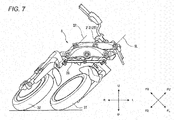
- Fig. 7 is a front view of the front part of the vehicle 1, when viewed from the front in the front-rear direction of the body frame 21, in such a state that the vehicle 1 is caused to lean and turned.
- Fig. 7 shows a state in which the vehicle 1 is steered or turned to the left while being caused to lean to the left.
- the front cover 221 is omitted from illustration.
- the left front wheel 31 When a steering operation is performed, the left front wheel 31 is turned counterclockwise about the left steering axis SL, while the right front wheel 32 is turned counterclockwise about the right steering axis SR.
- the left front wheel 31 and the right front wheel 32 lean to the left of the vehicle 1 together with the body frame 21. Namely, in this state, the link mechanism 5 exhibits the parallelogram shape.
- the tie-rod 99 moves to the left in the left-right direction of the body frame 21 and to the rear in the front-rear direction of the body frame 21 from the position where the body frame 21 is in the upright state.
- the configuration is known in which a recess portion (a relief portion) that the left shock absorber and the right shock absorber can enter is formed in the lower cross member. According to this configuration, the enlargement in size of the vehicle in the up-down direction can be suppressed while avoiding the interference of the left shock absorber and the right shock absorber with the lower cross member when the body frame leans. However, since the displacement amount of the left shock absorber and the right shock absorber towards the lower cross member increases as the maximum banking angle increases, a deeper recess portion needs to be formed. This will be true when attempting to increase the stroke, too.
- the dimension of the lower cross member in the up-down direction of the body frame needs to be increased. As a result, it becomes difficult to suppress the enlargement in size of the vehicle in the up-down direction.
- the inventors conceived that the goal described above can be achieved by devising the arrangement of the left shock absorber and the right shock absorber in place of the conventional countermeasures in which the shape of the lower cross member is devised.
- a portion of the lower cross member where the left shock absorber and the right shock absorber could interfere with the lower cross member is a portion that is positioned between the left steering axis and the right steering axis when the vehicle in which the body frame is standing upright is viewed from the front in the front-rear direction of the body frame.
- the portion is a portion that would be relatively much related to the rigidity of the lower cross member. In other words, it can be said that the portion is a portion having a relatively low degree of freedom in selecting a shape therefor from the viewpoint of ensuring
- a portion of the lower cross member where the left shock absorber could interfere with the lower cross member is a portion that is positioned between the left steering axis and the left end of the lower cross member when the vehicle in which the body frame is standing upright is viewed from the front in the front-rear direction of the body frame.
- a portion of the lower cross member where the right shock absorber could interfere with the lower cross member is a portion that is positioned between the right steering axis and the right end of the lower cross member when the vehicle in which the body frame is standing upright is viewed from the front in the front-rear direction of the body frame.
- These portions are portions that would be relatively less related to the rigidity of the lower cross member. In other words, it can be said that these portions are portions having a relatively high degree of freedom in selecting shapes therefor from the viewpoint of ensuring the rigidity of the lower cross member.
- the inventors conceived that it would be advantageous to dispose the left shock absorber and the right shock absorber in the position where the left shock absorber and the right shock absorber could interfere with the portions that would be relatively less related to the rigidity of the lower cross member and which have relatively high degree of freedom in selecting the shapes of the portions from the viewpoint of ensuring the rigidity of the lower cross member.
- Fig. 8 is a front view of the front part of the vehicle 1 resulting when viewed from the front in the front-rear direction of the body frame 21.
- the body frame 21 is in the upright state.
- the following description to be made while referring to Fig. 8 is based on the premise that the body frame 21 is in the upright state.
- the front cover 221 is omitted from illustration.
- Fig. 9 is a front view of the front part of the vehicle 1, when viewed from the front in the front-rear direction of the body frame 21, in which the body frame 21 is caused to lean to the left with the maximum angle.
- the front cover 221 is omitted from illustration.
- a distance LL between the left steering axis SL and a left end LCL of the lower cross member 52 in the left-right direction of the body frame 21 is shorter than a distance LI between the left steering axis SL and the right steering axis SR in the left-right direction of the body frame 21 when the vehicle 1 in which the body frame 21 is standing upright is viewed from the front in the front-rear direction of the body frame 21.
- a distance LR between the right steering axis SR and a right end LCR of the lower cross member 52 in the left-right direction of the body frame 21 is shorter than the distance LI between the left steering axis SL and the right steering axis SR in the left-right direction of the body frame 21 when the vehicle 1 in which the body frame 21 is standing upright is viewed from the front in the front-rear direction of the body frame 21.
- the left rear telescopic element 722 that serves as the left shock absorber is disposed so that the left telescopic axis EL is positioned on the left of the left steering axis SL in the left-right direction of the body frame when the vehicle 1 in which the body frame 21 is standing upright is viewed from the front in the front-rear direction of the body frame 21.
- the right rear telescopic element 822 that serves as the right shock absorber is disposed so that the right telescopic axis ER is positioned on the right of the right steering axis SR in the left-right direction of the body frame.
- the left shock absorber (the left rear telescopic element 722) moves away from the portion that is positioned between the left steering axis SL and the left end LCL of the lower cross member 52 as the vehicle 1 leans to the left.
- the right shock absorber (the right rear telescopic element 822) moves towards the portion that is positions between the right steering axis SR and the right end LCR of the lower cross member 52. Since the portion positioned on the right of the right steering axis SR has the high degree of freedom in utilizing the space, however, the shape and arrangement of the right suspension device 8 can easily be so selected as to avoid the interference of both members.
- the right shock absorber (the right rear telescopic element 822) and the lower cross member 52 in the up-down direction of the body frame 21.
- the right shock absorber (the right rear telescopic element 822) moves away from the portion that is positioned between the right steering axis SR and the right end LCR of the lower cross member 52 as the vehicle 1 leans to the right.
- the left shock absorber (the left rear telescopic element 722) moves towards the portion that is positions between the left steering axis SL and the left end LCL of the lower cross member 52.
- the shape and arrangement of the left suspension device 7 can easily be so selected as to avoid the interference of both members. Accordingly, it becomes easy to shorten the distance between the left shock absorber (the left rear telescopic element 722) and the lower cross member 52 in the up-down direction of the body frame 21.
- the shape and arrangement of the left suspension device 7 are selected so that the lower cross member 52 is positioned in a position 71a' that is axisymmetric with a left end 71 a of the left bracket 71 with respect to the left steering axis SL when the vehicle 1 in which the body frame 21 is caused to lean to the left with the maximum angle is viewed from the front in the front-rear direction of the body frame 21.
- the left end 71a of the left bracket 71 is an example of a point where a left edge of the left suspension device 7 is defined when the vehicle 1 in which the body frame 21 is caused to lean to the left with the maximum angle is viewed from the front in the front-rear direction of the body frame 21.
- the axisymmetric position 71 a' corresponds to a location where a right end of the left bracket 71 is positioned when the vehicle 1 is caused to lean to the left with the maximum angle at which the left rear telescopic element 722 is disposed on the right of the left steering axis SL in the left-right direction of the body frame 21.
- this case means that the lower cross member 52 interferes with the left bracket 71.
- the left bracket 71 that supports the left shock absorber (the left rear telescopic element 722) needs to be disposed below the left bracket 71, and the enlargement in size of the vehicle 1 in the up-down direction of the body frame 21 cannot be avoided.
- the left end portion of the lower cross member 52 and the left shock absorber (the left rear telescopic element 722) move way from each other.
- the portion positioned directly on the right of the right steering axis SR has the high degree of freedom in utilizing the space, it is easy to avoid the interference of the right end portion of the lower cross member 52 with the right shock absorbing device 82. Consequently, it becomes easy to reduce the distance between the lower cross member 52 and the left shock absorber (the left rear telescopic element 722) in the up-down direction of the body frame 21.
- the shape and arrangement of the right suspension device 8 are selected so that the lower cross member 52 is positioned in a position that is axisymmetric with a right end 81 a of the right bracket 81 with respect to the right steering axis SR when the vehicle 1 in which the body frame 21 is caused to lean to the right with the maximum angle is viewed from the front in the front-rear direction of the body frame 21, .
- the right end 81a of the right bracket 81 is an example of a point where a right edge of the right suspension device 8 is defined when the vehicle 1 in which the body frame 21 is caused to lean to the right with the maximum angle is viewed from the front in the front-rear direction of the body frame 21.
- the axisymmetric position corresponds to a location where a left end of the right bracket 81 is positioned when the vehicle 1 is caused to lean to the right with the maximum angle at which the right rear telescopic element 822 is disposed on the left of the right steering axis SR in the left-right direction of the body frame 21.
- this case means that the lower cross member 52 interferes with the right bracket 81.
- the right bracket 81 that supports the right shock absorber (the right rear telescopic element 822) needs to be disposed below the right bracket 81, and the enlargement in size of the vehicle 1 in the up-down direction of the body frame cannot be avoided.
- the right end portion of the lower cross member 52 and the right shock absorber (the right rear telescopic element 822) move way from each other.
- the portion positioned directly on the left of the left steering axis SL has the high degree of freedom in utilizing the space, it is easy to avoid the interference of the left end portion of the lower cross member 52 with the left shock absorbing device 72. Consequently, it becomes easy to reduce the distance between the lower cross member 52 and the right shock absorber (the right rear telescopic element 822) in the up-down direction of the body frame 21.
- a possible reduction in rigidity of the lower cross member 52 can be kept minimum.
- a recess portion where part of the right suspension device 8 can enter is formed in the portion that is positioned between the right steering axis SR and the right end LCR of the lower cross member 52 in order to avoid the interference of the right suspension device 8 with the lower cross member 52, a possible reduction in rigidity of the lower cross member 52 can be kept minimum.
- Fig. 10 is a plan view of the front part of the vehicle 1 viewed from the above in the up-down direction of the body frame 21 under a condition that the left front wheel 31 and the right front wheel 32 are turned to the left.
- the front cover 221 is omitted from illustration.
- a left portion of the front element 521 and a left portion of the rear element 522 of the lower cross member 52 are connected together by the left connecting member 523.
- a right portion of the front element 521 and a right portion of the rear element 522 of the lower cross member 52 are connected together by the right connecting member 524.
- the left portion of the front element 521, the left portion of the rear element 522 and the left connecting member 523 define a left recess portion 525 on a left peripheral edge portion of the lower cross member 52.
- the left peripheral edge portion of the lower cross member 52 is a portion that is positioned on the left of the lower left connecting axis CDL in the left-right direction of the body frame 21.
- the right portion of the front element 521, the right portion of the rear element 522 and the right connecting member 524 define a right recess portion 526 on a right peripheral edge portion of the lower cross member 52.
- the right peripheral edge portion of the lower cross member 52 represents a portion that is positioned on the right of the lower right connecting axis CDR in the left-right direction of the body frame 21.
- the left suspension device 7 comprises a left turn-restricting member 73.
- the left turn-restricting member 73 is a pin-shaped member that extends upwards from an upper portion of the left bracket 71 in the up-down direction of the body frame 21. When the vehicle 1 is standing upright, the left turn-restricting member 73 faces the left recess portion 525 of the lower cross member 52 with a certain space defined therebetween.
- the right suspension device 8 comprises a right turn-restricting member 83.
- the right turn-restricting member 83 is a pin-shaped member that extends upwards from an upper portion of the right bracket 81 in the up-down direction of the body frame 21. When the vehicle 1 is standing upright, the right turn-restricting member 83 faces the right recess portion 526 of the lower cross member 52 with a certain space defined therebetween.
- the right turn-restricting member 83 (an example of part of the right suspension device) enters the right recess portion 526 of the lower cross member 52.
- the left turn-restricting member 73 (an example of part of the left suspension device) enters the left recess portion 525 of the lower cross member 52.
- the left recess portion 525 is formed to avoid the interference of the lower cross member 52 with part of the left suspension device 7 and the right recess portion 526 is formed to avoid the interference of the lower cross member 52 with part of the right suspension device 8
- the influence that would reduce the rigidity of the lower cross member 52 can be suppressed. Consequently, since large contribution to the second advantageous effect and the third advantageous effect can be obtained, the enlargement in size of the vehicle 1 in the up-down direction can be suppressed even though the maximum banking angle and the stroke of the suspension devices are increased.
- an upper end LUE of the left recess portion 525 and an upper end RUE of the right recess portion 526 in the up-down direction of the body frame 21 are positioned above a straight line CDC that connects the lower left connecting axis CDL and the lower right connecting axis CDR in the up-down direction of the body frame 21.
- the left recess portion 525 is formed on the left peripheral edge portion of the lower cross member 52
- the right recess portion 526 is formed on the right peripheral edge portion of the lower cross member 52. Accordingly, although the depth over which the left turn-restricting member 73 and the right turn-restricting member 83 enter is increased by setting the positions of the upper end LUE of the left recess portion 525 and the upper end RUE of the right recess portion 526 in the way described above, the influence that would reduce the rigidity of the lower cross member 52 can be suppressed. Consequently, since large contribution to the second advantageous effect and the third advantageous effect can be obtained, the enlargement in size of the vehicle 1 in the up-down direction can be suppressed even though the maximum banking angle and the stroke of the suspension devices are increased.
- FIG. 11 shows schematically a positional relationship among the right side member 54, the right turn-restricting member 83 and the right connecting member 524 as viewed from the below in the up-down direction of the body frame 21.
- the right connecting member 524 has a right front wall 524a, a right side wall 524b and a right rear wall 524c.
- the right front wall 524a, the right side wall 524b and the right rear wall 524c define the right recess portion 526.
- the right connecting member 524 has a shape in which a space between the right front wall 524a and the right rear wall 524c becomes narrower as it moves to the right in the left-right direction of the body frame 21.
- the right connecting member 524 has a shape in which a space between the right front wall 524a and the right rear wall 524c becomes narrower as it moves upwards in the up-down direction of the body frame 21.
- the right turn-restricting member 83 enters the right recess portion 526 of the lower cross member 52.
- the left bracket 71 turns about the left steering axis SL
- the right bracket 81 turns about the right steering axis SR.
- the right turn-restricting member 83 provided on the right bracket 81 can move within the right recess portion 526 of the lower cross member 52.
- FIG. 11A shows a state in which the leaning angle of the body frame 21 to the left of the vehicle 1 is relatively small.
- the right bracket 81 not shown, turns clockwise in the figure about the right steering axis SR.
- the turning angle reaches ⁇ 1
- the right turn-restricting member 83 is brought into abutment with the right front wall 524a of the right connecting member 524, whereby the right bracket 81 is restricted from further turning.
- Fig. 11B shows a state in which the leaning angle of the body frame 21 to the left of the vehicle 1 is relatively great.
- the right bracket 81 turns clockwise in the figure about the right steering axis SR.
- the turning angle ⁇ 2 is smaller than the turning angle ⁇ 1.
- the left connecting member 523 has a left front wall, a left side wall and a left rear wall.
- the left front wall, the left side wall and the left rear wall define the left recess portion 525.
- the left connecting member 523 has a shape in which a space between the left front wall and the left rear wall becomes narrower toward the left in the left-right direction of the body frame 21.
- the left connecting member 523 has a shape in which a space between the left front wall and the left rear wall becomes narrower toward the above in the up-down direction of the body frame 21.
- the left turn-restricting member 73 enters the left recess portion 525 of the lower cross member 52.
- the left bracket 71 turns about the left steering axis SL
- the right bracket 81 turns about the right steering axis SR.
- the left turn-restricting member 73 provided on the left bracket 71 can move within the left recess portion 525 of the lower cross member 52.
- the left recess portion 525 that is defined by the left connecting member 523 has the shape described above, as the leaning angle of the body frame 21 to the right of the vehicle 1 increases, the movable amount of the left turn-restricting member73 within the left recess portion 52 is reduced. Consequently, as the leaning angle of the body frame 21 to the right of the vehicle 1 increases, the turnable angle of the steering member 6 for turning the vehicle 1 to the right is reduced.
- the mechanism that restricts the turning angle of the steering member 6 according to the leaning angle of the body frame 21 is provided by making use of the portion where the degree of freedom in selecting the shape is relatively high from the viewpoint of ensuring the rigidity of the lower cross member 52.
- the mechanism does not have to be provided in the location positioned between the left steering axis SL and the right steering axis SR of the lower cross member 52, that is, the portion that is involved relatively deeply in ensuring the rigidity of the lower cross member 52. Consequently, even though the maximum banking angle and the stroke of the suspension devices are increased, not only can the enlargement in size of the vehicle 1 in the up-down direction be restricted, but also a countermeasure to enhance the rigidity of the lower cross member 52 can easily be taken.
- the lower cross member 52 comprises the front element 521 and the rear element 522.
- the left end portion of the front element 521 and the left end portion of the rear element 522 are connected together by the left connecting member 523.
- the left recess portion 525 is defined by this left connecting member 523.
- the right end portion of the front element 521 and the right end portion of the rear element 522 are connected together by the right connecting member 524.
- the right recess portion 526 is defined by this right connecting member 524.
- the left recess portion 525 having the desired shape can easily be formed by the left connecting member 523 that is individual from the front element 521 and the rear element 522.
- the right recess portion 526 having the desired shape can easily be formed by the right connecting member 524 that is individual from the front element 521 and the rear element 522. Consequently, even though the maximum banking angle and the stroke of the suspension devices are increased, not only can the enlargement in size of the vehicle 1 in the up-down direction be restricted, but also the mechanism that restricts the turning angle of the steering member 6 according to the leaning angle of the body frame 21 can easily be formed.
- Fig. 9 shows a state in which the body frame 21 is caused to lean to the left of the vehicle 1 with the maximum angle.
- an upper edge 52a of the lower cross member 52 has a portion that is positioned above a lower edge 51a of the upper cross member 51 in the vertical direction. Accordingly, part of the lower cross member 52 seems to overlap the upper cross member 51.
- the enlargement in size of the link mechanism 5 in relation to the up-down direction of the body frame 21 can be suppressed. Consequently, even though the maximum banking angle and the stroke of the suspension devices are increased, the enlargement in size of the vehicle 1 in the up-down direction can be further suppressed.
- the left front wheel 31 is disposed on the left rear telescopic element 722 that serves as the left shock absorber in the left-right direction of the body frame 21.
- the right front wheel 32 is disposed on the left of the right rear telescopic element 822 that serves as the right shock absorber in the left-right direction of the body frame 21.
- the left front wheel 31 and the right front wheel 32 are disposed between the left shock absorber and the right shock absorber. According to this configuration, even though the maximum banking angle and the stroke of the suspension devices are increased, not only can the enlargement in size of the vehicle 1 in the up-down direction be suppressed, but also the enlargement in size of the vehicle 1 in the left-right direction can be suppressed.
- the left front wheel 31 is disposed on the right of the left front telescopic element 721 that serves as the left turn-restricting portion in the left-right direction of the body frame 21.
- the right front wheel 32 is disposed on the left of the right front telescopic element 821 that serves as the right turn-restricting portion in the left-right direction of the body frame 21.
- the left front wheel 31 and the right front wheel 32 are disposed between the left shock absorber, the left turn-restricting portion, the right shock absorber and the right turn-restricting portion. According to this configuration, even though the maximum banking angle and the stroke of the suspension devices are increased, not only can the enlargement in size of the vehicle 1 in the up-down direction be suppressed, but also the enlargement in size of the vehicle 1 in the left-right direction can be further suppressed.
- Fig.10 shows a state in which the steering member 6 is turned to the maximum turning angle to turn the vehicle 1 to the left.
- Fig. 10 shows a state in which the steering member 6 is turned to the maximum turning angle in the counterclockwise direction as viewed from the rider.
- a front end 821c of the right front telescopic element 821 that serves as the right turn-restricting portion and a front end 822c of the right rear telescopic element 822 that serves as the right shock absorber are disposed ahead of a rear end 99a of the tie-rod 99 in the front-rear direction of the body frame 21.
- the front end of the right front telescopic element 821 that serves as the right turn-restricting member and the front end of the right rear telescopic element 822 that serves as the right shock absorber are disposed ahead of the rear end 99a of the tie-rod 99 in the front-rear direction of the body frame 21.
- a lower edge 52b of the lower cross member 52 that is positioned between the lower left connecting axis CDL and the lower right connecting axis CDR is positioned below the straight line CDC that connects the lower left connecting axis CDL and the lower right connecting axis CDR in the up-down direction of the body frame 21 when the vehicle 1 in which the body frame 21 is standing upright is viewed from the direction that follows the lower left connecting axis CDL and the lower right connecting axis CDR.
- the left steering axis SL coincides with the center line of the left front wheel 31 in the left-right direction of the body frame 21
- the right steering axis SR coincides with the center line of the right front wheel 32 in the left-right direction of the body frame 21.
- a configuration shown in Fig. 12 can be adopted.
- a center line 31C of the left front wheel 31 in the left-right direction of the body frame 21 is positioned on the right of the left steering axis SL in the left-right direction of the body frame 21.
- a center line 32C of the right front wheel 32 in the left-right direction of the body frame 21 is positioned on the left of the right steering axis SR in the left-right direction of the body frame 21.
- the straight line CDC that connects the lower left connecting axis CDL and the lower right connecting axis CDR together is inclined relative to a line H that is parallel to the road surface.
- the lower right connecting axis CDR is positioned above the lower left connecting axis CDL. Consequently, a turning angle ⁇ 1 of the lower cross member 52 about the lower intermediate connecting axis CDI becomes smaller than a leaning angle ⁇ 2 at which the body frame 21 is caused to lean to the left of the vehicle 1 from the upright state.
- the turning angle ⁇ 1 is defined as an angle that is formed by the straight line CDC and a straight line FLR that is parallel to the left-right direction of the body frame 21.
- the leaning angle ⁇ 2 is defined as an angle that is formed by a line V orthogonal to the road surface and the front intermediate steering axis SIF or the rear intermediate steering axis SIB.
- the movable range of the link mechanism 5 in the up-down direction of the body frame 21 can be reduced. Consequently, even though the maximum banking angle and the stroke of the suspension devices are increased, the enlargement in size of the vehicle 1 in the up-down direction can be further suppressed.
- the lower cross member 52 comprises the front element 521 and the rear element 522.
- the left recess portion 525 of the lower cross member 52 is defined by the left connecting member 523 that connects the left end portion of the front element 521 and the left end portion of the rear element 522 together.
- the right recess portion 526 of the lower cross member 52 is defined by the right connecting member 524 that connects the right end portion of the front element 521 and the right end portion of the rear element 522 together.
- the left recess portion 525 can be formed directly on the left peripheral edge portion of the lower cross member 52 without using the left connecting member 523 that is an individual member.
- the right recess portion 526 can be formed directly on the right peripheral edge portion of the lower cross member 52 without forming the right connecting member 524 that is an individual member.
- the left rear telescopic element 722 of the left suspension device 7 serves as the left shock absorber
- the left front telescopic element 721, the left upper connecting member 723 and the left lower connecting member 724 serve as the left turn-restricting portion.
- the left front telescopic element 721 serves as the left shock absorber
- the left rear telescopic element 722 the left upper connecting member 723 and the left lower connecting member 724 serve as the left turn-restricting portion.
- the right rear telescopic element 822 of the right suspension device 8 serves as the right shock absorber
- the right front telescopic element 821, the right upper connecting member 823 and the right lower connecting member 824 serve as the right turn-restricting portion.
- the right front telescopic element 821 serves as the right shock absorber
- the right rear telescopic element 822, the right upper connecting member 823 and the right lower connecting member 824 serve as the right turn-restricting portion.
- both the telescopic element of the left suspension device 7 that serves as the left shock absorber and the telescopic element thereof that serves as the left turn-restricting portion are disposed directly on the left of the left front wheel 31 in the left-right direction of the body frame 21.
- the telescopic element that serves as the left turn-restricting portion can be disposed directly on the right of the left front wheel 31 in the left-right direction of the body frame 21.
- both the telescopic element of the right suspension device 8 that serves as the right shock absorber and the telescopic element thereof that serves as the right turn-restricting portion are disposed directly on the right of the right front wheel 32 in the left-right direction of the body frame 21.
- the telescopic element that serves as the right turn-restricting portion can be disposed directly on the left of the right front wheel 32 in the left-right direction of the body frame 21.
- both the front end of the telescopic element that serves as the right turn-restricting portion and the front end of the telescopic element that serves as the right shock absorber are disposed ahead of the rear end 99a of the tie-rod 99 in the front-rear direction of the body frame 21.
- a configuration can be adopted in which of the front end of the telescopic element that serves as the right turn-restricting portion and the front end of the telescopic element that serves as the right shock absorber, only the one that is disposed ahead of the other is disposed ahead of the rear end 99a of the tie-rod 99 in the front-rear direction of the body frame 21 in the same state.
- both the front end of the telescopic element that serves as the left turn-restricting portion and the front end of the telescopic element that serves as the left shock absorber are disposed ahead of the rear end 99a of the tie-rod 99 in the front-rear direction of the body frame 21.
- a configuration can be adopted in which of the front end of the telescopic element that serves as the left turn-restricting portion and the front end of the telescopic element that serves as the left shock absorber, only the one that is disposed ahead of the other is disposed ahead of the rear end 99a of the tie-rod 99 in the front-rear direction of the body frame 21 in the same state.
- the left front outer tube 721 a and the left rear outer tube 722a are supported on the left bracket 71.
- a configuration can be adopted in which the left front inner tube 721 b and the left rear inner tube 722b are supported on the left bracket 71.
- the right front outer tube 821a and the right rear outer tube 822a are supported on the right bracket 81.
- a configuration can be adopted in which the right front inner tube 821 b and the right rear inner tube 822b are supported on the right bracket 81.
- a left lower space 527 that is recessed upwards with a slight extent is formed on a lower portion of the lower cross member 52 that is positioned between the lower left connecting portion 53b and the lower intermediate connecting portion 211b.
- the left lower space 527 may be used as a relief portion where part of the left suspension device 7 enters when the vehicle 1 is caused to lean to the left of the vehicle 1.
- a right lower space 528 that is recessed upwards with a slight extent is formed on a lower portion of the lower cross member 52 that is positioned between the lower right connecting portion 54b and the lower intermediate connecting portion 211b.
- the right lower space 528 may be used as a relief portion where part of the right suspension device 8 enters when the vehicle 1 is caused to lean to the right of the vehide 1.
- the vehicle 1 comprises the single rear wheel 4.
- the vehicle 1 may comprise a plurality of rear wheels.
- the upper cross member 51 is the single plate member, while the lower cross member 52 comprises the front element 521 and the rear element 522.
- the upper cross member 51 also comprises a front element and a rear element.
- a configuration can be adopted in which at least one of the upper cross member 51 and the lower cross member 52 comprises a left plate member that is supported on the link supporting portion 212 and the left side member 53 and a right plate member that is supported on the link supporting portion 212 and the right side member 54.
- the handlebar 61 is made up of the single member that extends in the left-right direction of the body frame.
- the handlebar 61 is made up of a left handlebar portion configured to be operated by the left hand of the rider and a right handlebar portion configured to be operated by the right hand of the rider that are provided as individual members, as long as steering force to turn the left front wheel 31 and the right front wheel 32 can be inputted through the handlebar 61.
- the steering force transmission mechanism 9 comprises the intermediate transmission plate 93, the left transmission plate 94, the right transmission plate 95, the intermediate joint 96, the left joint 97, the right joint 98, and the tie-rod 99.
- the intermediate transmission plate 93, the left transmission plate 94, the right transmission plate 95, the intermediate joint 96, the left joint 97, and the right joint 98 can be replaced by appropriate mechanisms such as universal joints as required, as long as the steering force inputted from the handlebar 61 can be transmitted to the left suspension device 7 and the right suspension device 8 by way of the tie-rod 99.
- the word “parallel” means that two straight lines which do not intersect each other as members while they are inclined at an angle falling within the range of ⁇ 40 degrees are comprised therein.
- the expression reading "along a certain direction” means that a case where something inclines at an angle falling within the range of ⁇ 40 degrees relative to the certain direction is comprised therein.
- the expression reading "something extends in a certain direction” means that a case where something extends while being inclined at an angle falling within the range of ⁇ 40 degrees relative to the certain direction is comprised therein.
- the expression “so as not to be movable relative to the body frame 21” means that a certain part or member is caused to lean in the left-right direction of the vehicle 1 together with the body frame 21 when the body frame 21 is caused to lean in the left-right direction of the vehicle 1.
- the expression “so as not to be movable relative to the body frame 21” may comprehend not only a case where a certain part or member is directly fixed to the body frame but also a case where the certain part of member is fixed to a vehicle component (a fuel tank, a bracket, the power unit 24, etc.) which is fixed on the body frame 21.
- the term “fixed” may comprehend a case that a certain part or member is fixed by way of a damping member or the like.
- the invention can be implemented with many different embodiments. This description should be understood to provide a principle embodiment of the invention. The preferred embodiment which is at least described or illustrated in this description is so described or illustrated based on the understanding that the embodiment is not intended to limit the invention.
- the invention comprehends every embodiment which comprises an equivalent element, a modification, a deletion, a combination (for example, a combination of characteristics of various embodiments), an improvement and an alteration which can be recognized by those skilled in the art to which the invention pertains based on the embodiment disclosed in this description.
- the limitative matters of claims should be construed widely based on terms used in the claims and hence should not be limited by the embodiment described in this specification or the prosecution of this patent application.
- Those embodiments should be construed as non-exclusive.
- the terms "preferable” and “may” should be construed as being non-exclusive, and those terms mean, respectively, that it is “preferable but not limited thereto” and that it “may be acceptable but not limited thereto.”
Landscapes
- Engineering & Computer Science (AREA)
- Mechanical Engineering (AREA)
- Automatic Cycles, And Cycles In General (AREA)
- Axle Suspensions And Sidecars For Cycles (AREA)
- Vehicle Body Suspensions (AREA)
Abstract
Description
- The present disclosure relates to a vehicle equipped with a leanable body frame and two front wheels.
- A vehicle described in, for example,
Patent Literature 1 comprises a body frame that leans to the left or right of the vehicle when the vehicle turns left or right and two front wheels that are arranged side by side in a left-right direction of the body frame. This type of vehicle is a vehicle which is able to turn with its body frame leaning from a vertical direction. More specifically, the body frame leans to the right of the vehicle when the vehicle turns to the right, while when the vehicle turns to the left, the body frame leans to the left of the vehicle. In this type of vehicle, a distance between the two front wheels which are arranged side by side in the left-right direction of the body frame is very short, compared with a general four-wheeled vehicle. Consequently, this type of vehicle is compact in size in relation to the left-right direction of the body frame. - The vehicle described in
Patent Literature 1 comprises a so-called parallelogram type link mechanism. The parallelogram type link mechanism can be disposed above the two front wheels. On the other hand, a link mechanism that is known as a double wishbone type link mechanism is disposed between the two front wheels in the left-right direction of the body frame. Accordingly, the vehicle equipped with the parallelogram type link mechanism is more compact in size in relation to the left-right direction of the body frame than the vehicle equipped with the double wishbone type link mechanism. - The parallelogram type link mechanism comprises an upper cross member, a lower cross member, a left side member and a right side member. The upper cross member, the lower cross member, the left side member and the right side member are connected so that the upper cross member and the lower cross member keep postures parallel to each other and the left side member and the right side member keep postures parallel to each other. The upper cross member and the lower cross member are supported on the body frame so as to turn about axes that extend in a front-rear direction of the body frame. The left side member is supported at a left portion of the upper cross member and a left portion of the lower cross member so as to turn abut axes that extend in the front-rear direction of the body frame. The right side member is supported at a right portion of the upper cross member and a right portion of the lower cross member so as to turn abut axes that extend in the front-rear direction of the body frame. Namely, the upper cross member, the lower cross member, the left side member and the right side member turn individually about the axes that extend in the front-rear direction of the body frame. Accordingly, movable ranges of the upper cross member, the lower cross member, the left side member and the right side member when the parallelogram type link mechanism operates are relatively small in relation to a front-rear direction of the vehicle.
- The vehicle described in
Patent Literature 1 comprises a telescopic suspension device. The telescopic suspension device includes a left suspension device and a right suspension device. The left suspension device supports one (a left front wheel) of the two front wheels at a lower portion thereof and is supported on the left side member at an upper portion thereof. The left suspension device attenuates an upward displacement of the left front wheel in an up-down direction of the body frame relative to the upper portion thereof. The right suspension device supports the other (a right front wheel) of the two front wheels at a lower portion thereof and is supported on the right side member at an upper portion thereof. The right suspension device attenuates an upward displacement of the right front wheel in the up-down direction of the body frame relative to the upper portion thereof. The telescopic suspension device comprises an inner tube and an outer tube. The inner tube and the outer tube are displaced relatively along a telescopic axis that extends in the up-down direction of the body frame. Accordingly, movable ranges of the inner tube and the outer tube when the telescopic suspension device operates are relatively small in the front-rear direction of the vehicle. - Consequently, the vehicle comprises the parallelogram type link mechanism and the telescopic suspension device is compact in size in the front-rear direction.
-
- [Patent Literature 1] International Patent Publication No.
2014/065396 - In the vehicle described above, it is desired that a maximum displacement amount (hereinafter, referred to as a stroke) of the suspension device is increased. In a case where the inner tube and the outer tube are made long in the up-down direction of the body frame, the stroke can be increased accordingly. However, the vehicle is increased in size in the up-down direction.
- Additionally, it is desired that a maximum leaning angle (hereinafter, referred to as a maximum banking angle) of the body frame is increased. In a case where a space defined between a left member that includes the left suspension device and the left front wheel and a right member that includes the right suspension device and the right front wheel in the left-right direction of the body frame is increased, it becomes difficult for the left member and the right member to interfere with each other even when the body frame is caused to lean. In other words, the maximum banking angle can be increased by increasing the space defined between the left member and the right member in the left-right direction of the body frame. In a case where the space defined between the left member and the right member in the left-right direction of the body frame is expanded, however, the space defined between the left side member that supports the left suspension device and the right side member that supports the right suspension device in the left-right direction of the body frame is expanded. This increases the size of the vehicle in the left-right direction. In addition, distances from the turning centers of the upper cross member and the lower cross member about which they turn relative to the body frame to the left side member and the right side member become long. Accordingly, the movable range of the link mechanism becomes wide not only in the left-right direction but also in the up-down direction of the body frame. Consequently, the vehide is also increased in size in the up-down direction.
- Thus, there is a goal to increase the maximum banking angle and the stroke of the suspension device while suppressing the enlargement of the vehicle in the up-down direction.
- It is therefore one aspect for achieving the goal is a vehicle comprising:
- a body frame;
- a left front wheel and a right front wheel that are arranged side by side in a left-right direction of the body frame;
- a link mechanism disposed above the left front wheel and the right front wheel in an up-down direction of the body frame, and configured to change positions of the left front wheel and the right front wheel relative to the body frame to cause the body frame to lean to left or right of the vehicle;
- a left suspension device of a telescopic type supporting the left front wheel and configured to attenuate or absorb a displacement of the left front wheel toward the link mechanism in the up-down direction of the body frame; and
- a right suspension device of a telescopic type supporting the right front wheel and configured to attenuate or absorb a displacement of the right front wheel toward the link mechanism in the up-down direction of the body frame,
- an upper cross member;
- a lower cross member disposed below the upper cross member in the up-down direction of the body frame;
- a left side member disposed above the left front wheel in the up-down direction of the body frame and supporting the left suspension device such that the left suspension device is turnable about a left steering axis extending in the up-down direction of the body frame;
- a right side member disposed above the right front wheel in the up-down direction of the body frame and supporting the right suspension device such that the right suspension device is turnable about a right steering axis extending in the up-down direction of the body frame;
- a left shock absorber including a left inner portion and a left outer portion that are movable relative to each other in a left telescopic axis extending in the up-down direction of the body frame; and
- a left turn-restricting portion including a left guide portion and a left guided portion that are movable relative to each other in a direction parallel to the left telescopic axis and configured to restrict relative turning of the left inner portion and the left outer portion;
- a right shock absorber including a right inner portion and a right outer portion that are movable relative to each other in a right telescopic axis extending in the up-down direction of the body frame; and
- a right turn-restricting portion including a right guide portion and a right guided portion that are movable relative to each other in a direction parallel to the right telescopic axis and configured to restrict relative turning of the right inner portion and the right outer portion;
- The configuration is known in which a recess portion (a relief portion) that the left shock absorber and the right shock absorber can enter is formed in the lower cross member. According to this configuration, the enlargement in size of the vehicle in the up-down direction can be suppressed while avoiding the interference of the left shock absorber and the right shock absorber with the lower cross member when the body frame leans. However, since the displacement amount of the left shock absorber and the right shock absorber towards the lower cross member increases as the maximum banking angle increases, a deeper recess portion needs to be formed. This will be true when attempting to increase the stroke, too. In order to avoid a reduction in rigidity that would be caused by the formation of the recess portion, the dimension of the lower cross member in the up-down direction of the body frame needs to be increased. As a result, it becomes difficult to suppress the enlargement in size of the vehicle in the up-down direction.
- The inventors conceived that the goal described above can be achieved by devising the arrangement of the left shock absorber and the right shock absorber in place of the conventional countermeasures in which the shape of the lower cross member is devised.
- In a case where the left shock absorber is disposed so that the left telescopic axis is positioned on the right of the left steering axis in the left-right direction of the body frame and the right shock absorber is disposed so that the right telescopic axis is positioned on the left of the right steering axis in the left-right direction of the body frame when the vehicle in which the body frame is standing upright is viewed from the front in the front-rear direction of the body frame, a portion of the lower cross member where the left shock absorber and the right shock absorber could interfere with the lower cross member is a portion that is positioned between the left steering axis and the right steering axis when the vehicle in which the body frame is standing upright is viewed from the front in the front-rear direction of the body frame. The portion is a portion that would be relatively much related to the rigidity of the lower cross member. In other words, it can be said that the portion is a portion having a relatively low degree of freedom in selecting a shape therefor from the viewpoint of ensuring the rigidity.
- On the other hand, in a case where the left shock absorber is disposed so that the left telescopic axis is positioned on the left of the left steering axis in the left-right direction of the body frame when the vehicle in which the body frame is standing upright is viewed from the front in the front-rear direction of the body frame, a portion of the lower cross member where the left shock absorber could interfere with the lower cross member is a portion that is positioned between the left steering axis and the left end of the lower cross member when the vehicle in which the body frame is standing upright is viewed from the front in the front-rear direction of the body frame. Similarly, in a case where the right shock absorber is disposed so that the right telescopic axis is positioned on the right of the right steering axis in the left-right direction of the body frame when the vehicle in which the body frame is standing upright is viewed from the front in the front-rear direction of the body frame, a portion of the lower cross member where the right shock absorber could interfere with the lower cross member is a portion that is positioned between the right steering axis and the right end of the lower cross member when the vehicle in which the body frame is standing upright is viewed from the front in the front-rear direction of the body frame. These portions are portions that would be relatively less related to the rigidity of the lower cross member. In other words, it can be said that these portions are portions having a relatively high degree of freedom in selecting shapes therefor from the viewpoint of ensuring the rigidity of the lower cross member.
- The inventors conceived that it would be advantageous to dispose the left shock absorber and the right shock absorber in the position where the left shock absorber and the right shock absorber could interfere with the portions that would be relatively less related to the rigidity of the lower cross member and which have relatively high degree of freedom in selecting the shapes of the portions from the viewpoint of ensuring the rigidity of the lower cross member.
- Based on the conceiving described above, the left rear telescopic element that serves as the left shock absorber is disposed so that the left telescopic axis is positioned on the left of the left steering axis in the left-right direction of the body frame when the vehicle in which the body frame is standing upright is viewed from the front in the front-rear direction of the body frame. On the other hand, the right rear telescopic element that serves as the right shock absorber is disposed so that the right telescopic axis is positioned on the right of the right steering axis in the left-right direction of the body frame. This configuration is advantageous in the following points.
- Firstly, the left shock absorber moves away from the portion that is positioned between the left steering axis and the left end of the lower cross member as the vehicle leans to the left. On the other hand, the right shock absorber moves towards the portion that is positions between the right steering axis and the right end of the lower cross member. Since the portion positioned on the right of the right steering axis has the high degree of freedom in utilizing the space, however, the shape and arrangement of the right suspension device can easily be so selected as to avoid the interference of both members. Accordingly, it becomes easy to shorten the distance between the right shock absorber and the lower cross member in the up-down direction of the body frame. Similarly, the right shock absorber moves away from the portion that is positioned between the right steering axis and the right end of the lower cross member as the vehicle leans to the right. On the other hand, the left shock absorber moves towards the portion that is positions between the left steering axis and the left end of the lower cross member. Since the portion positioned on the left of the left steering axis has the high degree of freedom in utilizing the space, however, the shape and arrangement of the left suspension device can easily be so selected as to avoid the interference of both members. Accordingly, it becomes easy to shorten the distance between the left shock absorber and the lower cross member in the up-down direction of the body frame.
- Secondly, even though a recess portion where part of the left suspension device can enter is formed in the portion that is positioned between the left steering axis and the left end of the lower cross member in order to avoid the interference of the left suspension device with the lower cross member, a possible reduction in rigidity of the lower cross member can be kept minimum. Similarly, even though a recess portion where part of the right suspension device can enter is formed in the portion that is positioned between the right steering axis and the right end of the lower cross member in order to avoid the interference of the right suspension device with the lower cross member, a possible reduction in rigidity of the lower cross member can be kept minimum.
- Thirdly, since the dimension of the lower cross member in the up-down direction of the body frame does not have to be increased, a distance between the upper cross member and the lower cross member in the up-down direction of the body frame that could avoid the interference therebetween can be shortened.
- Even though the maximum banking angle and the stroke of the suspension devices are increased, the enlargement in size of the vehicle in the up-down direction can be suppressed by the synergetic action of the first advantageous effect, the second advantageous effect and the third advantageous effect.
- In connection with the first advantageous effect, the above vehicle may be configured as follows.
- The lower cross member is positioned in a position that is axisymmetric with a left edge of the left suspension device relative to the left steering axis when the vehicle in which the body frame is caused to lean to the left with a maximum angle.
- The lower cross member is positioned in a position that is axisymmetric with a right edge of the right suspension device relative to the right steering axis when the vehicle in which the body frame is caused to lean to the right with a maximum angle.
- The axisymmetric position corresponds to a location where the right end of the left suspension device is positioned when the vehicle is caused to lean to the left with the maximum angle at which the left shock absorber is disposed on the right of the left steering axis in the left-right direction of the body frame. Namely, this case means that the lower cross member interferes with the left suspension device. To avoid the interference, the left suspension device that supports the left shock absorber needs to be disposed below the left suspension device, and the enlargement in size of the vehicle in the up-down direction of the body frame cannot be avoided. According to the configuration of this embodiment, when the vehicle leans to the left, the left end portion of the lower cross member and the left shock absorber move way from each other. On the other hand, since the portion positioned directly on the right of the right steering axis has the high degree of freedom in utilizing the space, it is easy to avoid the interference of the right end portion of the lower cross member with the right shock absorbing device. Consequently, it becomes easy to reduce the distance between the lower cross member and the left shock absorber in the up-down direction of the body frame.
- The axisymmetric position corresponds to a location where a left end of the right suspension device is positioned when the vehicle is caused to lean to the right with the maximum angle at which the right shock absorber is disposed on the left of the right steering axis in the left-right direction of the body frame. Namely, this case means that the lower cross member interferes with the right suspension device. To avoid the interference, the right suspension device that supports the right shock absorber needs to be disposed below the right suspension device, and the enlargement in size of the vehicle in the up-down direction of the body frame cannot be avoided. According to the configuration of this embodiment, when the vehicle leans to the right, the right end portion of the lower cross member and the right shock absorber move way from each other. On the other hand, since the portion positioned directly on the left of the left steering axis has the high degree of freedom in utilizing the space, it is easy to avoid the interference of the left end portion of the lower cross member with the left shock absorbing device. Consequently, it becomes easy to reduce the distance between the lower cross member and the right shock absorber in the up-down direction of the body frame.
- The above vehicle may be configured as follows.
- A left portion of the lower cross member is supported on a lower portion of the left side member such that the left portion of the lower cross member is turnable about a lower left connecting axis extending in the front-rear direction of the body frame.
- A right portion of the lower cross member is supported on a lower portion of the right side member such that the right portion of the lower cross member is turnable about a lower right connecting axis extending in the front-rear direction of the body frame.
- The lower cross member has a left recess portion at a left peripheral edge portion that is positioned on the left of the lower left connecting axis in the left-right direction of the body frame.
- The lower cross member has a right recess portion at a right peripheral edge portion that is positioned on the right of the lower right connecting axis in the left-right direction of the body frame.
- A part of the right suspension device is able to enter the right recess portion at least when the body frame is caused to lean from an upright state thereof to the left of the vehicle with a maximum angle.
- A part of the left suspension device is able to enter the left recess portion at least when the body frame is caused to lean from the upright state thereof to the right of the vehicle with a maximum angle.
- According to the configuration described above, even though the left recess portion is formed to avoid the interference of the lower cross member with part of the left suspension device, and the right recess portion is formed to avoid the interference of the lower cross member with part of the right suspension device, the influence that would reduce the rigidity of the lower cross member can be suppressed. Consequently, since large contribution to the second advantageous effect and the third advantageous effect can be obtained, the enlargement in size of the vehicle in the up-down direction can be suppressed even though the maximum banking angle and the stroke of the suspension devices are increased.
- In this case, the above vehicle may be configured as follows.
- An upper end of the left recess portion and an upper end of the right recess portion in the up-down direction of the body frame is positioned above a straight line connecting the lower left connecting axis and the lower right connecting axis in the up-down direction of the body frame.
- The left recess portion is formed on the left peripheral edge portion of the lower cross member, and the right recess portion is formed on the right peripheral edge portion of the lower cross member. Accordingly, although the depth over which the left turn-restricting member and the right turn-restricting member enter is increased by setting the positions of the upper end of the left recess portion and the upper end of the right recess portion in the way described above, the influence that would reduce the rigidity of the lower cross member can be suppressed. Consequently, since large contribution to the second advantageous effect and the third advantageous effect can be obtained, the enlargement in size of the vehicle in the up-down direction can be suppressed even though the maximum banking angle and the stroke of the suspension devices are increased.
- The above vehicle may be configured so as to comprise:
- a steering member being turnable about a turn axis relative to the body frame; and
- a steering force transmission mechanism configured to cause the left suspension device and the right suspension device to turn in a direction that the steering member is turned.
- The above vehide may be configured as follows.
- The part of the left suspension device in the left recess portion is movable within the left recess portion in accordance with the turn of the left suspension device about the left steering axis.
- The left recess portion is configured such that a movable amount of the part of the left suspension device within the left recess portion is reduced as a leaning angle of the body frame to the right of the vehicle increases.
- The part of the right suspension device in the right recess portion is movable within the right recess portion in accordance with the turn of the right suspension device about the right steering axis.
- The right recess portion is configured such that a movable amount of the part of the right suspension device within the right recess portion is reduced as a leaning angle of the body frame to the left of the vehicle increases.
- Namely, the mechanism that restricts the turning angle of the steering member according to the leaning angle of the body frame is provided by making use of the portion where the degree of freedom in selecting the shape is relatively high from the viewpoint of ensuring the rigidity of the lower cross member. In other words, the mechanism does not have to be provided in the location positioned between the left steering axis and the right steering axis of the lower cross member, that is, the portion that is involved relatively deeply in ensuring the rigidity of the lower cross member. Consequently, even though the maximum banking angle and the stroke of the suspension devices are increased, not only can the enlargement in size of the vehicle in the up-down direction be restricted, but also a countermeasure to enhance the rigidity of the lower cross member can easily be taken.
- In this case, the above vehicle may be configured as follows.
- The lower cross member comprises:
- a front element disposed ahead of the left side member and the right side member in the front-rear direction of the body frame;
- a rear element disposed behind of the left side member and the right side member in the front-rear direction of the body frame;
- a left connecting member connecting a left end portion of the front element and a left end portion of the rear element; and
- a right connecting member connecting a right end portion of the front element and a right end portion of the rear element.
- The left recess portion is defined by the left connecting member.
- The right recess portion is defined by the right connecting member.
- According to the configuration described above, the left recess portion having the desired shape can easily be formed by the left connecting member that is individual from the front element and the rear element. Similarly, the right recess portion having the desired shape can easily be formed by the right connecting member that is individual from the front element and the rear element. Consequently, even though the maximum banking angle and the stroke of the suspension devices are increased, not only can the enlargement in size of the vehicle in the up-down direction be restricted, but also the mechanism that restricts the turning angle of the steering member according to the leaning angle of the body frame can easily be formed.
- The above vehicle may be configured as follows.
- A left portion of the lower cross member is supported on a lower portion of the left side member such that the left portion of the lower cross member is turnable about a lower left connecting axis extending in the front-rear direction of the body frame.
- A right portion of the lower cross member is supported on a lower portion of the right side member such that the right portion of the lower cross member is turnable about a lower right connecting axis extending in the front-rear direction of the body frame.
- An upper edge of the lower cross member has a portion positioned above a lower edge of the upper cross member in a vertical direction when the body frame is caused to lean from an upright state thereof to the left or the right of the vehicle with a maximum leaning angle, and viewed from a direction following the lower left connecting axis and the lower right connecting axis.
- By defining the positional relationship between the upper edge of the lower cross member and the lower edge of the upper cross member in the way described above, the enlargement in size of the link mechanism in relation to the up-down direction of the body frame can be suppressed. Consequently, even though the maximum banking angle and the stroke of the suspension devices are increased, the enlargement in size of the vehicle in the up-down direction can be further suppressed.
- The above vehicle may be configured as follows.
- A left portion of the lower cross member is supported on a lower portion of the left side member such that the left portion of the lower cross member is turnable about a lower left connecting axis extending in the front-rear direction of the body frame.
- A right portion of the lower cross member is supported on a lower portion of the right side member such that the right portion of the lower cross member is turnable about a lower right connecting axis extending in the front-rear direction of the body frame.
- When the body frame is caused to lean from an upright state thereof to the left or the right of the vehicle with a maximum leaning angle, a turn angle of the lower cross member about the lower left connecting axis and the lower right connecting axis is smaller than the maximum leaning angle.
- According to this confguration, the movable range of the link mechanism in the up-down direction of the body frame can be reduced. Consequently, even though the maximum banking angle and the stroke of the suspension devices are increased, the enlargement in size of the vehicle in the up-down direction can be further suppressed.
- The above vehicle may be configured as follows.
- The left front wheel is disposed on the right of the left shock absorber in the left-right direction of the body frame.
- The right front wheel is disposed on the left of the right shock absorber in the left-right direction of the body frame.
- Namely, the left front wheel and the right front wheel are disposed between the left shock absorber and the right shock absorber. According to this configuration, even though the maximum banking angle and the stroke of the suspension devices are increased, not only can the enlargement in size of the vehicle in the up-down direction be suppressed, but also the enlargement in size of the vehicle in the left-right direction can be suppressed.
- In this case, the above vehicle may be configured as follows.
- The left front wheel is disposed on the right of the left turn-restricting portion in the left-right direction of the body frame.
- The right front wheel is disposed on the left of the right turn-restricting portion in the left-right direction of the body frame.
- Namely, the left front wheel and the right front wheel are disposed between the left shock absorber, the left turn-restricting portion, the right shock absorber and the right turn-restricting portion. According to this configuration, even though the maximum banking angle and the stroke of the suspension devices are increased, not only can the enlargement in size of the vehicle in the up-down direction be suppressed, but also the enlargement in size of the vehicle in the left-right direction can be further suppressed.
- The above vehicle may be configured to comprise:
- a steering member being turnable about a turn axis relative to the body frame; and
- a steering force transmission mechanism configured to cause the left suspension device and the right suspension device to turn in a direction that the steering member is turned.
- The above vehicle may be configured as follows.
- The steering force transmission mechanism comprises:
- an intermediate turning portion being turnable about an intermediate steering axis in accordance with the turn of the steering member;
- a left turning portion disposed directly on the left of the intermediate turning portion in the left-right direction of the body frame, and connected to the left suspension device so as to be turnable about the left steering axis;
- a right turning portion disposed directly on the right of the intermediate turning portion in the left-right direction of the body frame, and connected to the right suspension device so as to be turnable about the right steering axis; and
- a connecting portion connecting the intermediate turning portion with the left turning portion and the right turning portion.
- At least one of a front end of the left shock absorber and a front end of the left turn-restricting portion is positioned ahead of a rear end of the connecting portion in the front-rear direction of the body frame when the steering member is turned clockwise viewed from a rider with a maximum angle.
- At least one of a front end of the right shock absorber and a front end of the right turn-restricting portion is positioned ahead of the rear end of the connecting portion in the front-rear direction of the body frame when the steering member is turned counterclockwise viewed from the rider with a maximum angle.
- According to this configuration, since the necessity of considering the avoidance of the interference of the lower cross member with the left suspension device and the right suspension device is reduced, it is possible to suppress the enlargement in size of the steering force transmission mechanism in relation to the front-rear direction of the body frame. Even though the maximum banking angle and the stroke of the suspension devices are increased, not only can the enlargement in size of the vehicle in the up-down direction be suppressed, but also the enlargement in size of the vehicle in the front-rear direction can be suppressed.
- The above vehicle may be configured as follows.
- A left portion of the lower cross member is supported on a lower portion of the left side member such that the left portion of the lower cross member is turnable about a lower left connecting axis extending in the front-rear direction of the body frame.
- A right portion of the lower cross member is supported on a lower portion of the right side member such that the right portion of the lower cross member is turnable about a lower right connecting axis extending in the front-rear direction of the body frame.
- A lower edge of the lower cross member that is positioned between the lower left connecting axis and the lower right connecting axis is positioned below a straight line connecting the lower left connecting axis and the lower right connecting axis in the up-down direction of the body frame when the vehicle in which the body frame is standing upright is viewed from a direction following the lower left connecting axis and the lower right connecting axis.
- According to this configuration, even though a relief portion where the lower edge of the lower cross member is recessed upwards with a large extent is not formed between the lower left connecting axis and the lower right connecting axis, it is possible to avoid the interference of the lower cross member with part of the left suspension device and part of the right suspension device. By adopting this configuration, the rigidity of the lower cross portion can be enhanced. In other words, the dimension of the lower cross member in the up-down direction of the body frame does not have to be increased in order to ensure the rigidity thereof. Consequently, even though the maximum banking angle and the stroke of the suspension devices are increased, the enlargement in size of the vehicle in the up-down direction can be suppressed.
-
-
Fig. 1 is a left side view entirely showing a vehicle according to one embodiment. -
Fig. 2 is a left side view showing a front portion of the vehicle ofFig. 1 in an enlarged manner. -
Fig. 3 is a front view showing the front portion of the vehicle ofFig. 1 . -
Fig. 4 is a plan view showing the front portion of the vehicle ofFig. 1 . -
Fig. 5 is a plan view showing the front portion of the vehicle ofFig. 1 when steering is performed. -
Fig. 6 is a front view showing the front portion of the vehicle ofFig. 1 when leaning is performed. -
Fig. 7 is a front view showing the front portion of the vehicle ofFig. 1 when steering and leaning are performed. -
Fig. 8 is a front view showing the front portion of the vehicle ofFig. 1 . -
Fig. 9 is a front view showing the front portion of the vehicle ofFig. 1 when leaning is performed. -
Fig. 10 is a plan view showing the front portion of the vehicle ofFig. 1 when steering is performed. -
Figs. 11A and 11B are schematic views for explaining mechanism for restricting a steering angle. -
Fig. 12 is a front view showing a front portion of the vehicle according to a modified example. - Referring to the accompanying drawings, an exemplary embodiment will be described in detail below.
- In the accompanying drawings, an arrow F denotes a front or forward direction of a vehicle. An arrow B denotes a back/rear or backward/rearward direction of the vehicle. An arrow U denotes an up or upward direction of the vehicle. An arrow D denotes a down or downward direction of the vehicle. An arrow R denotes a right or rightward direction of the vehicle. An arrow L denotes a left or leftward direction of the vehicle.
- A vehicle turns with a body frame being caused to lean to the left or right of the vehicle from a vertical direction. Then, in addition to the directions based on the vehicle, directions based on the body frame will be defined. In the accompanying drawings, an arrow FF denotes a front or forward direction of the body frame. An arrow FB denotes a back/rear or backward/rearward of the body frame. An arrow FU denotes an up or upward direction of the body frame. An arrow FD denotes a down or downward direction of the body frame. An arrow FR denotes a right or rightward direction of the body frame. An arrow FL denotes a left or leftward direction of the body frame.
- In this description, a "front-rear direction of the body frame," a "left-right direction of the body frame" and an "up-down direction of the body frame" mean a front-rear direction, a left-right direction and an up-down direction based on the body frame when viewed from a rider who rides the vehicle. "A side of or sideways of the body frame" means directly on the right or left in the left-right direction of the body frame.
- In this description, an expression "extending in the front-rear direction of the vehicle body frame" includes a fact that it extends while being inclined in relation to the front-rear direction of the vehicle body frame and means that it extends in a direction closer to the front-rear direction of the vehicle body frame than the left-right direction and up-down direction of the vehicle body frame.
- In this description, an expression "extending in the left-right direction of the vehicle body frame" includes a fact that it extends while being inclined in relation to the left-right direction of the vehicle body frame and means that it extends in a direction closer to the left-right direction of the vehicle body frame than the front-rear direction and up-down direction of the vehicle body frame.
- In this description, an expression "extending in the up-down direction of the vehicle body frame" includes a fact that it extends while being inclined in relation to the up-down direction of the vehicle body frame and means that it extends in a direction closer to the up-down direction of the vehicle body frame than the left-right direction and front-rear direction of the vehicle body frame.
- In this description, an expression reading the "vehicle is standing upright or in an upright state" or the "body frame is standing upright or in the upright state" means a state in which the vehicle is not steered at all and the up-down direction of the body frame coincides with the vertical direction. In this state, the directions based on the vehicle coincide with the directions based on the body frame. When the vehicle is turning with the body frame caused to lean to the left or right from the vertical direction, the left-right direction of the vehicle does not coincide with the left-right direction of the body frame. Similarly, the up-down direction of the vehicle does not coincide with the up-down direction of the body frame. However, the front-rear direction of the vehicle coincides with the front-rear direction of the body frame.
- In this description, an expression reading "directly on the left of a member A in the left-right direction of the body frame" denotes a space through which the member A passes when the member A is translated to the left in the left-right direction of the body frame. An expression reading "directly on the right of the member A" is also defined in the same way.
- In this description, an expression reading "on the left of the member A in the left-right direction of the body frame" includes not only the space through which the member A passes when the member A is translated to the left in the left-right direction of the body frame but also a space which expands from the space in directions which are at right angles to the left-right direction of the body frame. An expression reading "on the right of the member A" is also defined in the same way.
- In this description, an expression reading "directly above the member A in the up-down direction of the body frame" denotes a space through which the member A passes when the member A is translated upwards in the up-down direction of the body frame. An expression reading "directly below the member A" is also defined in the same way.
- In this description, an expression reading "above the member A in the up-down direction of the body frame" includes not only the space through which the member A passes when the member A is translated upwards in the up-down direction of the body frame but also a space which expands from the space in directions which are at right angles to the up-down direction of the body frame. An expression reading "below the member A" is also defined in the same way.
- In this description, an expression reading "directly ahead of the member A in the front-rear direction of the body frame" denotes a space through which the member A passes when the member A is translated to the front in the front-rear direction of the body frame. An expression reading "directly behind the member A" is also defined in the same way.
- In this description, an expression reading "ahead of the member A in the front-rear direction of the body frame" includes not only the space through which the member A passes when the member A is translated to the front in the front-rear direction of the body frame but also a space which expands from the space in directions which are at right angles to the front-rear direction of the body frame. An expression reading "behind the member A" is also defined in the same way.
- In this description, "rotation, rotating or rotated" means that a member is displaced at an angle of 360 degrees or more about an axis thereof. In this description, "turn, turning or turned" means that a member is displaced at an angle less than 360 degrees about an axis thereof.
- Referring to
Figs. 1 to 12 , avehicle 1 according to an embodiment will be described. As shown inFig. 1 , thevehicle 1 comprises a vehiclemain body 2, twofront wheels 3, arear wheel 4, alink mechanism 5 and asteering member 6. Thevehicle 1 is a vehicle that comprises a leanable body frame and the twofront wheels 3 arranged side by side in the left-right direction of the body frame. - The vehicle
main body 2 comprises abody frame 21, abody cover 22, aseat 23, anengine unit 24, and arear arm 25. - In
Fig. 1 , thebody frame 21 is in the upright state. The following description to be made while referring toFig. 1 is based on the premise that thebody frame 21 is in the upright state.Fig. 1 is a left side view resulting when the whole of thevehicle 1 is viewed from the left in the left-right direction of thebody frame 21. -
Fig. 2 is a view resulting when a front part of thevehicle 1 is viewed from the left in the left-right direction of thebody frame 21. InFig. 2 , thebody frame 21 is in the upright state. The following description to be made while referring toFig. 2 is based on the premise that thebody frame 21 is in the upright state. - The
body frame 21 comprises ahead pipe 211, alink supporting portion 212 and amain frame 213. Thehead pipe 211 supports the steeringmember 6. Thelink supporting portion 212 supports thelink mechanism 5. Themain frame 213 supports theseat 23, theengine unit 24 and therear arm 25. - The
rear arm 25 is disposed directly behind themain frame 213 in the front-rear direction of thebody frame 21. Therear arm 25 extends in the front-rear direction of thebody frame 21. A front end portion of therear arm 25 is supported by themain frame 213 and theengine unit 24 and is allowed to turn about an axis that extends in the left-to-rear direction of thebody frame 21. A rear end portion of therear arm 25 supports therear wheel 4. - The body cover 22 is a body part that covers at least part of a group of constituent parts that make up the
vehicle 1. The body cover 22 includes afront cover 221, a pair of left and rightfront fenders 222 and arear front fender 223. - As shown in
Fig. 1 , thefront cover 221 is disposed directly ahead of theseat 23 in the front-rear direction of thebody frame 21. Thefront cover 221 covers thelink mechanism 5, the steeringmember 6 and at least part of a steeringforce transmission mechanism 9. Thefront cover 221 is disposed so as not to be movable relative to thebody frame 21. InFig. 2 , thefront cover 221 is omitted from illustration. - At least portions of the pair of left and right
front fenders 222 are individually disposed directly below thefront cover 221. At least portions of the pair of left and rightfront fenders 222 are disposed directly above the pair of left and rightfront wheels 3, respectively. - At least part of the
rear wheel 4 is disposed below theseat 23 in the up-down direction of thebody frame 21. At least part of therear wheel 4 is disposed directly below therear front fender 223 in the up-down direction of thebody frame 21. - The
vehicle 1 according to the embodiment is a vehicle on which a rider mounts in a posture of straddling thebody frame 21. Namely, when riding thevehicle 1, part of thebody frame 21, which is disposed ahead of theseat 23 on which the rider sits in the front-rear direction of thebody frame 21, is disposed between the legs of the rider. The rider rides on thevehicle 1 in a posture of holding themain frame 213 or thefront cover 221 that is positioned ahead of theseat 23 in the front-rear direction of thebody frame 21 by the legs therebetween. - When viewing the
vehicle 1 from the left-right direction of thebody frame 21, theengine unit 24 is disposed ahead of a front end of therear wheel 4 in the front-rear direction of thebody frame 21. Theengine unit 24 is disposed so as not to be movable relative to thebody frame 21. Theengine unit 24 is disposed so as not to be movable relative to themain frame 213. Theengine 24 produces power for driving thevehicle 1. The driving force so produced is transmitted to therear wheel 4. - The
head pipe 211 is disposed at a front portion of thevehicle 1. When viewing thevehicle 1 from the left in the left-right direction of thebody frame 21, an upper portion of thehead pipe 211 is disposed behind a lower portion of thehead pipe 211 in the front-rear direction of thebody frame 21. - The steering
member 6 comprises ahandlebar 61 and anupstream steering shaft 62. Theupstream steering shaft 62 extends downwards from a central portion of thehandlebar 61 in the left-right direction. Theupstream steering shaft 62 is supported on thehead pipe 211 so as to turn about a rear intermediate steering axis SIB. - The
link supporting portion 212 is disposed directly ahead of thehead pipe 211 in the front-rear direction of thebody frame 21. When viewing thevehicle 1 from the left in the left-right direction of thebody frame 21, an upper portion of thelink supporting portion 212 is disposed behind a lower portion of thelink supporting portion 212 in the front-rear direction of thebody frame 21. -
Fig. 3 is a front view of the front part of thevehicle 1 resulting when viewed from the front in the front-rear direction of thebody frame 21. InFig. 3 , thebody frame 21 is in the upright state. The following description to be made while referring toFig. 3 is based on the premise that thebody frame 21 is in the upright state. InFig. 3 , thefront cover 221 is omitted from illustration. - The two
front wheels 3 include aleft front wheel 31 and a rightfront wheel 32. Theleft front wheel 31 is disposed on the left of thehead pipe 211 and thelink supporting portion 212 which make up part of thebody frame 21 in the left-right direction of thebody frame 21. Theright front wheel 32 is disposed on the right of thehead pipe 211 and thelink supporting portion 212 which make up part of thebody frame 21 in the left-right direction of thebody frame 21. Theleft front wheel 31 and theright front wheel 32 are arranged side by side in the left-right direction of thebody frame 21. - In the
vehicle 1 according to this embodiment, thelink mechanism 5 adopts a four parallel joint link system (also referred to as a parallelogram link). - The
link mechanism 5 is disposed above theleft front wheel 31 and theright front wheel 32 in the up-down direction of thebody frame 21. Thelink mechanism 5 comprises anupper cross member 51, alower cross member 52, aleft side member 53 and aright side member 54. Thelink mechanism 5 is not interlocked with the turning of theupstream steering shaft 62 about the rear intermediate steering axis SIB which occurs in association with the operation of thehandlebar 61. Namely, thelink mechanism 5 does not turn about the rear intermediate steering axis SIB relative to thebody frame 21. - The
link supporting portion 212 has an upper intermediate connectingportion 212a. An intermediate portion of theupper cross member 51 is supported on thelink supporting portion 212 via the upper intermediate connectingportion 212a. Theupper cross member 51 is able to turn relative to thelink supporting portion 212 about an upper intermediate connecting axis CUI that passes the upper intermediate connectingportion 212a and extends in the front-rear direction of thebody frame 21. - The
link supporting portion 212 has a lower intermediate connectingportion 212b. An intermediate portion of thelower cross member 52 is supported on thelink supporting portion 212 via the lower intermediate connectingportion 212b. Thelower cross member 52 is able to turn relative to thelink supporting portion 212 about a lower intermediate connecting axis CDI that passes the lower intermediate connectingportion 212b and extends in the front-rear direction of thebody frame 21. - The
left side member 53 has an upperleft connecting portion 53a. A left end portion of theupper cross member 51 is connected to theleft side member 53 via the upperleft connecting portion 53a. Theupper cross member 51 is able to turn relative to theleft side member 53 about an upper left connecting axis CUL that passes the upper left connecting 53a and which extends in the front-rear direction of thebody frame 21. - The
right side member 54 has an upperright connecting portion 54a. A right end portion of theupper cross member 51 is connected to theright side member 54 via the upperright connecting portion 54a. Theupper cross member 51 is able to turn relative to theright side member 54 about an upper right connecting axis CUR that passes the upperright connecting portion 54a and which extends in the front-rear direction of thebody frame 21. - The
left side member 53 has a lowerleft connecting portion 53b. A left end portion of thelower cross member 52 is connected to theleft side member 53 via the lowerleft connecting portion 53b. Thelower cross member 52 is able to turn relative to theleft side member 53 about a lower left connecting axis CDL that passes the lower left connecting 53b and which extends in the front-rear direction of thebody frame 21. - The
right side member 54 has a lowerright connecting portion 54b. A right end portion of thelower cross member 52 is connected to theright side member 54 via the lowerright connecting portion 54b. Thelower cross member 52 is able to turn relative to theright side member 54 about a lower right connecting axis CDR that passes the lowerright connecting portion 54b and which extends in the front-rear direction of thebody frame 21. -
Fig. 4 is a plan view of the front part of thevehicle 1 when viewed from the above in the up-down direction of thebody frame 21. InFig. 4 , thebody frame 21 is in the upright state. The following description to be made while referring toFig. 4 is based on the premise that thebody frame 21 is in the upright state. InFig. 4 , thefront cover 221 is omitted from illustration. - The
upper cross member 51 is disposed ahead of thelink supporting portion 212 in the front-rear direction of thebody frame 21. Theupper cross member 51 is a plate member that extends in the left-right direction of thebody frame 21 without being curved in the front-rear direction of thebody frame 21. - As shown in
Figs. 2 and4 , thelower cross member 52 is disposed below theupper cross member 51 in the up-down direction of thebody frame 21. Thelower cross member 52 comprises afront element 521 and arear element 522. Thefront element 521 is disposed ahead of thelink supporting portion 212, theleft side member 53 and theright side member 54 in the front-rear direction of thebody frame 21. Therear element 522 is disposed behind thelink supporting portion 212, theleft side member 53 and theright side member 54 in the front-rear direction of thebody frame 21. Thefront element 521 and therear element 522 extend in the left-right direction of thebody frame 21 without being curved in the front-rear direction of thebody frame 21. - As shown in
Fig. 4 , thelower cross member 52 comprises a left connectingmember 523 and aright connecting member 524. Theleft connecting member 523 connects a left end portion of thefront element 521 and a left end portion of therear element 522 together. Theright connecting member 524 connects a right end portion of thefront element 521 and a right end portion of therear element 522. - As shown in
Figs. 3 and4 , theleft side member 53 is disposed directly on the left of thelink supporting portion 212 in the left-right direction of thebody frame 21. Theleft side member 53 is disposed above theleft front wheel 31 in the up-down direction of thebody frame 21. Theleft side member 53 extends in a direction in which thelink supporting portion 212 extends. An upper portion of theleft side member 53 is disposed behind a lower portion thereof in the front-rear direction of thebody frame 21. - As shown in
Figs. 3 and4 , theright side member 54 is disposed directly on the right of thelink supporting portion 212 in the left-right direction of thebody frame 21. Theright side member 54 is disposed above theright front wheel 32 in the up-down direction of thebody frame 21. Theright side member 54 extends in the direction in which thelink supporting portion 212 extends. An upper portion of theright side member 54 is disposed behind a lower portion thereof in the front-rear direction of thebody frame 21. - The
upper cross member 51, thelower cross member 52, theleft side member 53 and theright side member 54 are supported on thelink supporting portion 212 so that theupper cross member 51 and thelower cross member 52 keep their postures that are parallel to each other and theleft side member 53 and theright side member 54 keep their postures that are parallel to each other. - As shown in
Figs. 2 to 4 , thevehicle 1 comprises aleft suspension device 7. Theleft suspension device 7 comprises aleft bracket 71 and a leftshock absorbing device 72. - The
left bracket 71 comprises a left turning member, not shown, that is provided at an upper portion thereof. The left turning member is disposed in an interior of theleft side member 53 and extends in the same orientation as the direction in which theleft side member 53 extends. The left turning member is able to turn about a left steering axis SL relative to theleft side member 53. Namely, theleft bracket 71 is connected to theleft side member 53 so as to turn about the left steering axis SL. The left steering axis SL extends in the direction in which theleft side member 53 extends. As shown inFig. 3 , the left steering axis SL extends parallel to the rear intermediate steering axis SIB of theupstream steering shaft 62 in the up-down direction of thebody frame 21. As shown inFig. 4 , the left steering axis SL extends parallel to the rear intermediate steering axis SIB of theupstream steering shaft 62 in the up-down direction of thebody frame 21. - The left
shock absorbing device 72 is a so-called telescopic shock absorbing mechanism. The leftshock absorbing device 72 is configured so as to attenuate or absorb a displacement of theleft front wheel 31 towards thelink mechanism 5 in the up-down direction of thebody frame 21. As shown inFig. 2 , the leftshock absorbing device 72 comprises a left fronttelescopic element 721, a left reartelescopic element 722, a leftupper connecting member 723, a left lower connecting member 714 and aleft axle 725. - The left front
telescopic element 721 comprises a left frontouter tube 721a (an example of a left guide portion) and a left frontinner tube 721 b (an example of a left guided portion). An outer diameter of the left frontouter tube 721a is greater than an outer diameter of the left frontinner tube 721 b. The left frontouter tube 721 a is supported by theleft bracket 71. The left frontinner tube 721 b is connected to the left frontouter tube 721 a so as to slide along a left telescopic axis EL. - The left rear
telescopic element 722 comprises a left rearouter tube 722a (an example of a left outer portion) and a left rearinner tube 722b (an example of a left inner portion). An outer diameter of the left rearouter tube 722a is greater than an outer diameter of the left rearinner tube 722b. The left rearouter tube 722a is disposed directly behind the left frontouter tube 721 a in the front-rear direction of thebody frame 21. The left rearouter tube 722a is supported by theleft bracket 71. The left rearinner tube 722b is disposed directly behind the left frontinner tube 721 b in the front-rear direction of thebody frame 21. The left rearinner tube 722b is connected to the left rearouter tube 722a so as to slide along the left telescopic axis EL. - The left
upper connecting member 723 connects the left frontouter tube 721a and the left rearouter tube 722a together. - The left lower connecting
member 724 connects the left frontinner tube 721 b and the left rearinner tube 722b together. - One end (a left end) of the
left axle 725 is supported on the left frontinner tube 721 b and the left rearinner tube 722b via the left lower connectingmember 724. The other end (a right end) of theleft axle 725 supports theleft front wheel 31. - The left
shock absorbing device 72 is configured so as to attenuate or absorb a displacement of theleft front wheel 31 towards thelink mechanism 5 in the up-down direction of thebody frame 21. In particular, the left reartelescopic element 722 is configured so as to serve as a left shock absorber. The left fronttelescopic element 721, the leftupper connecting member 723 and the left lower connectingmember 724 serve as a left turn-restricting portion and restrict the relative turning between the left rearouter tube 722a and the left rearinner tube 722b. - As shown in
Figs. 2 to 4 , thevehicle 1 comprises aright suspension device 8. Theright suspension device 8 comprises aright bracket 81 and a rightshock absorbing device 82. The configuration of theright suspension device 8 is symmetrical with theleft suspension device 7 when thevehicle 1 is viewed from the left in the left-right direction of thebody frame 21. Thus, theright suspension device 8 is not illustrated separately, and only reference numerals for theright suspension device 8 will be shown inFig. 2 . - The
right bracket 81 comprises a right turning member, not shown, at an upper portion thereof. The right turning member is disposed in an interior of theright side member 54 and extends in the same orientation as the direction in which theright side member 54 extends. The right turning member is able to turn about a right steering axis SR relative to theright side member 54. Namely, theright bracket 81 is connected to theright side member 54 so as to turn about the right steering axis SR. The right steering axis SR extends in the direction in which theright side member 54 extends. As shown inFig. 3 , the right steering axis SR extends parallel to the rear intermediate steering axis SIB of theupstream steering shaft 62 in the up-down direction of thebody frame 21. As shown inFig. 4 , the right steering axis SR extends parallel to the rear intermediate steering axis SIB of theupstream steering shaft 62 in the up-down direction of thebody frame 21. - The right
shock absorbing device 82 is a so-called telescopic shock absorbing mechanism. As shown inFig. 2 , the rightshock absorbing device 82 comprises a right fronttelescopic element 821, a right reartelescopic element 822, a rightupper connecting member 823, a right lower connectingmember 824 and aright axle 825. - The right front
telescopic element 821 comprises a right frontouter tube 821a (an example of a right guide portion) and a right frontinner tube 821b (an example of a right guided portion). An outer diameter of the right frontouter tube 821 a is greater than an outer diameter of the right frontinner tube 821 b. The right frontouter tube 821 a is supported by theright bracket 81. The right frontinner tube 821b is connected to the right frontouter tube 821a so as to slide along a right telescopic axis ER. - The right rear
telescopic element 822 comprises a right rearouter tube 822a (an example of a right outer portion) and a right rearinner tube 822b (an example of a right inner portion). An outer diameter of the right rearouter tube 822a is greater than an outer diameter of the right rearinner tube 822b. The right rearouter tube 822a is disposed directly behind the right frontouter tube 821 a in the front-rear direction of thebody frame 21. The right rearouter tube 822a is supported by theright bracket 81. The right rearinner tube 822b is disposed directly behind the right frontinner tube 821b in the front-rear direction of thebody frame 21. The right rearinner tube 822b is connected to the right rearouter tube 822a so as to slide along the right telescopic axis ER. - The right
upper connecting member 823 connects the right frontouter tube 821a and the right rearouter tube 822a together. - The right lower connecting
member 824 connects the right frontinner tube 821 b and the right rearinner tube 822b together. - One end (a right end) of the
right axle 825 is supported on the right frontinner tube 821 b and the right rearinner tube 822b via the right lower connectingmember 824. The other end (a left end) of theright axle 825 supports theright front wheel 32. - The right
shock absorbing device 82 is configured so as to attenuate or absorb a displacement of theright front wheel 32 towards thelink mechanism 5 in the up-down direction of thebody frame 21. In particular, the right reartelescopic element 822 is configured so as to serve as a right shock absorber. The right fronttelescopic element 821, the rightupper connecting member 823 and the right lower connectingmember 824 serve as a right turn-restricting portion and restrict the relative turning between the right rearouter tube 822a and the right rearinner tube 822b. - As shown in
Figs. 2 to 4 , thevehicle 1 comprises a steeringforce transmission mechanism 9. The steeringforce transmission mechanism 9 comprises adownstream steering shaft 91, a connectingdevice 92, anintermediate transmission plate 93, aleft transmission plate 94, aright transmission plate 95, an intermediate joint 96, a left joint 97, a right joint 98 and a tie-rod 99. - The
downstream steering shaft 91 is supported on thelink supporting portion 212 so as to turn about a front intermediate steering axis SIF. The front intermediate steering axis SIF extends parallel to the rear intermediate steering axis SIB about which theupstream steering shaft 62 turns. - The connecting
device 92 connects theupstream steering shaft 62 and thedownstream steering shaft 91 together. The connectingdevice 92 is configured so as to be displaced in association with the turning of theupstream steering shaft 62. Thedownstream steering shaft 91 is configured so as to turn in association with the displacement of the connectingdevice 92. Namely, the connectingdevice 92 is configured so as to transmit a turning operation of theupstream steering shaft 62 to thedownstream steering shaft 91. - The intermediate transmission plate 93 (an example of an intermediate turning portion) is connected to a lower portion of the
downstream steering shaft 91. Theintermediate transmission plate 93 is not able to turn relative to thedownstream steering shaft 91. Theintermediate transmission plate 93 is able to turn about the front intermediate steering axis SIF relative to thelink supporting portion 212. - The left transmission plate 94 (an example of a left turning portion) is disposed directly on the left of the
intermediate transmission plate 93 in the left-right direction of thebody frame 21. Theleft transmission plate 94 is connected to a lower portion of theleft bracket 71. Theleft transmission plate 94 is not able to turn relative to theleft bracket 71. Theleft transmission plate 94 is able to turn about the left steering axis SL relative to theleft side member 53. - The right transmission plate 95 (an example of a right turning portion) is disposed directly on the right of the
intermediate transmission plate 93 in the left-right direction of thebody frame 21. Theright transmission plate 95 is connected to a lower portion of theright bracket 81. Theright transmission plate 95 is not able to turn relative to theright bracket 81. Theright transmission plate 95 is able to turn about the right steering axis SR relative to theright side member 54. - As shown in
Fig. 4 , the intermediate joint 96 is connected to a front portion of theintermediate transmission plate 93 via a shaft portion that extends in the up-down direction of thebody frame 21. Theintermediate transmission plate 93 and the intermediate joint 96 are allowed to turn relative to each other about this shaft portion. - The left joint 97 is disposed on the left of the intermediate joint 96 in the left-right direction of the
body frame 21. The left joint 97 is connected to a front portion of theleft transmission plate 94 via a shaft portion that extends in the up-down direction of thebody frame 21. Theleft transmission plate 94 and the left joint 97 are allowed to turn relative to each other about this shaft portion. - The right joint 98 is disposed on the right of the intermediate joint 96 in the left-right direction of the
body frame 21. The right joint 98 is connected to a front portion of theright transmission plate 95 via a shaft portion that extends in the up-down direction of the body frame. Theright transmission plate 95 and the right joint 98 are allowed to turn relative to each other about this shaft portion. - A shaft portion that extends in the front-rear direction of the
body frame 21 is provided at a front portion of the intermediate joint 96. A shaft portion that extends in the front-rear direction of thebody frame 21 is provided at a front portion of the left joint 97. A shaft portion that extends in the front-rear direction of thebody frame 21 is provided at a front portion of the right joint 98. - The tie-rod 99 (an example of a connecting portion) extends in the left-right direction of the
body frame 21. The tie-rod 99 is connected to the intermediate joint 96, the left joint 97 and the right joint 98 via those shaft portions. The tie-rod 99 and the intermediate joint 96 is able to turn relative to each other about the shaft portion that is provided at the front portion of the intermediate joint 96. The tie-rod 99 and the left joint 97 is able to turn relative to each other about the shaft portion that is provided at the front portion of the left joint 97. The tie-rod 99 and the right joint 98 is able to turn relative to each other about the shaft portion that is provided at the front portion of the right joint 98. - The
left transmission plate 94 is connected to theintermediate transmission plate 93 via the left joint 97, the tie-rod 99, and the intermediate joint 96. Theright transmission plate 95 is connected to theintermediate transmission plate 93 via the right joint 98, the tie-rod 99 and the intermediate joint 96. Theleft transmission plate 94 and theright transmission plate 95 are connected to each other via the left joint 97, the tie-rod 99 and the right joint 98. In other words, the tie-rod 99 connects theintermediate transmission plate 93 to theleft transmission plate 94 and theright transmission plate 95. - Next, referring to
Figs. 4 and5 , a steering operation of thevehicle 1 will be described.Fig. 5 is a plan view of the front part of thevehicle 1 that is in such a state that theleft front wheel 31 and theright front wheel 32 are turned to the left, as viewed from the above in the up-down direction of thebody frame 21. InFig. 5 , thefront cover 221 is omitted from illustration. - When the rider operates the
handlebar 61, theupstream steering shaft 62 is turned about the rear intermediate steering axis SIB relative to thehead pipe 211. The turning operation of theupstream steering shaft 62 is transmitted to thedownstream steering shaft 91 via the connectingdevice 92. When the turn of theupstream steering shaft 62 is so transmitted to thedownstream steering shaft 91, thedownstream steering shaft 91 is turned relative to thelink supporting portion 212 about the front intermediate steering axis SIF. In the case of thedownstream steering shaft 91 being turned to the left as shown inFig. 5 , the steeringshaft 91 turns in a direction indicated by an arrow T. In association with the turn of thedownstream steering shaft 91, theintermediate transmission plate 93 turns in the direction indicated by the arrow T about the front intermediate steering axis SIF relative to thelink supporting portion 212. - In association with the turning of the
intermediate transmission plate 93 in the direction indicated by the arrow T, the intermediate joint 96 turns relative to theintermediate transmission plate 93 in a direction indicated by an arrow S. This causes the tie-rod 99 to move to the left in the left-right direction of thebody frame 21 and to the rear in the front-rear direction of thebody frame 21 while maintaining its posture. - In association with the movement of the tie-
rod 99, the left joint 97 and the right joint 98 turn in the direction indicated by the arrow S relative to theleft transmission plate 94 and theright transmission plate 95, respectively. This turns theleft transmission plate 94 and theright transmission plate 95 in the direction indicated by the arrow T while allowing the tie-rod 99 to keep its posture. - When the
left transmission plate 94 turns in the direction indicated by the arrow T, theleft bracket 71, which is not able to turn relative to theleft transmission plate 94, is turned in the direction indicated by the arrow T about the left steering axis SL relative to theleft side member 53. - When the
right transmission plate 95 turns in the direction indicated by the arrow T, theright bracket 81, which is not able to turn relative to theright transmission plate 95, is turned in the direction indicated by the arrow T about the right steering axis SR relative to theright side member 54. - When the
left bracket 71 is turned in the direction indicated by the arrow T, the leftshock absorbing device 72, which is supported on theleft bracket 71, is turned in the direction indicated by the arrow T about the left steering axis SL relative to theleft side member 53. When the leftshock absorbing device 72 is turned in the direction indicated by the arrow T, theleft front wheel 31, which is supported on the leftshock absorbing device 72, is turned in the direction indicated by the arrow T about the left steering axis SL relative to theleft side member 53. - When the
right bracket 81 is turned in the direction indicated by the arrow T, the rightshock absorbing device 82, which is supported on theright bracket 81, is turned in the direction indicated by the arrow T about the right steering axis SR relative to theright side member 54. When the rightshock absorbing device 82 is turned in the direction indicated by the arrow T, theright front wheel 32, which is supported on the rightshock absorbing device 82, is turned in the direction indicated by the arrow T about the right steering axis SR relative to theright side member 54. - When the rider operates the
handlebar 61 so as to turn to the right, the elements described above turn in opposite directions to the directions in which they turn when the vehicle turns to the left. Since the elements merely move the other way around in relation to the left-right direction, the detailed description thereof will be omitted here. - Thus, as has been described heretofore, the steering
member 6 transmits the steering force to theleft front wheel 31 and theright front wheel 32 in response to the operation of thehandlebar 61 by the rider. Theleft front wheel 31 and theright front wheel 32 turn about the left steering axis SL and the right steering axis SR, respectively, in the direction corresponding to the direction in which thehandlebar 61 is operated by the rider. - Next, referring to
Figs. 3 and6 , a leaning operation of thevehicle 1 will be described.Fig. 6 is a front view of the front part of thevehicle 1, when viewed from the front in the front-rear direction of thebody frame 21, with thebody frame 21 caused to lean to the left of thevehicle 1. InFig. 6 , thefront cover 221 is omitted from illustration. - As shown in
Fig. 3 , when thevehicle 1 is viewed from the front of thebody frame 21 that is standing upright, thelink mechanism 5 exhibits a rectangular shape. As shown inFig. 6 , when thevehicle 1 is viewed from the front of thebody frame 21 that is leaning, thelink mechanism 5 exhibits a parallelogram shape. The operation of thelink mechanism 5 is interlocked with the leaning of thebody frame 21 in the left-right direction. The operation of thelink mechanism 5 means that the shape of thelink mechanism 5 changes as a result of theupper cross member 51 and thelower cross member 52 turning relative to thelink supporting portion 212 about the upper intermediate connecting axis CUI and the lower intermediate connecting axis CDI, respectively, and theupper cross member 51, thelower cross member 52, theleft side member 53 and theright side member 54 turning relatively about the upper left connecting axis CUL, the upper right connecting axis CUR, the lower left connecting axis CDL and the lower right connecting axis CDR, respectively. - For example, as shown in
Fig. 6 , when the rider causes thevehicle 1 to lean to the left, thehead pipe 211 and thelink supporting portion 212 lean to the left from the vertical direction. When thehead pipe 211 and thelink supporting portion 212 lean, theupper cross member 51 turns counterclockwise about the upper intermediate connecting axis CUI that passes the upper intermediate connectingportion 212a relative to thelink supporting portion 212 when viewed from the front of thevehicle 1. Similarly, thelower cross member 52 is turned counterclockwise about the lower intermediate connecting axis CDI that passes the lower intermediate connectingportion 212b relative to thehead pipe 211 when viewed from the front of thevehicle 1. This causes theupper cross member 51 to move to the left in the left-right direction of thebody frame 21 relative to thelower cross member 52. - By moving in the way described above, the
upper cross member 51 turns counterclockwise about the upper left connecting axis CUL that passes the upperleft connecting portion 53a and the upper right connecting axis CUR that passes the upperright connecting portion 54a relative to theleft side member 53 and theright side member 54, respectively when viewed from the front of thevehicle 1. Similarly, thelower cross member 52 turns counterclockwise about the lower left connecting axis CDL that passes the lowerleft connecting portion 53b and the lower right connecting axis CDR that passes the lowerright connecting portion 54b relative to theleft side member 53 and theright side member 54, respectively, when viewed from the front of thevehicle 1. By moving in the way described above, theleft side member 53 and theright side member 54 lean to the left of thevehicle 1 from the vertical direction while maintaining their postures that are parallel to thehead pipe 211 and thelink supporting portion 212. - As this occurs, the
lower cross member 52 moves to the left in the left-right direction of thebody frame 21 relative to the tie-rod 99. As a result of thelower cross member 52 moving in the way described above, the shaft portions that are provided at the respective front portions of the intermediate joint 96, the left joint 97 and the right joint 98 turn relative to the tie-rod 99. This allows the tie-rod 99 to hold a posture that is parallel to theupper cross member 51 and thelower cross member 52. - As the
left side member 53 leans to the left of thevehicle 1, theleft bracket 71 that is supported on theleft side member 53 via the left turning member leans to the left of thevehicle 1. In association with the leftward leaning of theleft bracket 71, the leftshock absorbing device 72 that is supported on theleft bracket 71 also leans to the left of thevehicle 1. As a result of the leftshock absorbing device 72 leaning in the way described above, theleft front wheel 31 that is supported on the leftshock absorbing device 72 leans to the left of thevehicle 1 while maintaining its posture that is parallel to thehead pipe 211 and thelink supporting portion 212. - As the
right side member 54 leans to the left of thevehicle 1, theright bracket 81 that is supported on theright side member 54 via the right turning member leans to the left of thevehicle 1. In association with the leftward leaning of theright bracket 81, the rightshock absorbing device 82 that is supported on theright bracket 81 also leans to the left of thevehicle 1. As a result of the rightshock absorbing device 82 leaning in the way described above, theright front wheel 32 that is supported on the rightshock absorbing device 82 leans to the left of thevehicle 1 while maintaining its posture that is parallel to thehead pipe 211 and thelink supporting portion 212. - The description of the leaning operations of the
left front wheel 31 and theright front wheel 32 is made based on the vertical direction. However, when thevehicle 1 leans (when thelink mechanism 5 is actuated to operate), the up-down direction of thebody frame 21 is not coincident with the vertical direction. In the event of this being described based on the up-down direction of thebody frame 21, when thelink mechanism 5 is actuated to operate, theleft front wheel 31 and theright front wheel 32 change their relative positions in the up-down direction of thebody frame 21. In other words, thelink mechanism 5 changes the relative positions of theleft front wheel 31 and theright front wheel 32 in the up-down direction of thebody frame 21 to thereby cause thebody frame 21 to lean to the left or right of thevehicle 1 from the vertical direction. - When the rider causes the
vehicle 1 to lean to the right, the elements lean to the right. Since the elements merely move the other way around in relation to the left-right direction, the detailed description thereof will be omitted here. -
Fig. 7 is a front view of the front part of thevehicle 1, when viewed from the front in the front-rear direction of thebody frame 21, in such a state that thevehicle 1 is caused to lean and turned.Fig. 7 shows a state in which thevehicle 1 is steered or turned to the left while being caused to lean to the left. InFig. 7 , thefront cover 221 is omitted from illustration. - When a steering operation is performed, the
left front wheel 31 is turned counterclockwise about the left steering axis SL, while theright front wheel 32 is turned counterclockwise about the right steering axis SR. When a leaning operation is performed, theleft front wheel 31 and theright front wheel 32 lean to the left of thevehicle 1 together with thebody frame 21. Namely, in this state, thelink mechanism 5 exhibits the parallelogram shape. The tie-rod 99 moves to the left in the left-right direction of thebody frame 21 and to the rear in the front-rear direction of thebody frame 21 from the position where thebody frame 21 is in the upright state. - The configuration is known in which a recess portion (a relief portion) that the left shock absorber and the right shock absorber can enter is formed in the lower cross member. According to this configuration, the enlargement in size of the vehicle in the up-down direction can be suppressed while avoiding the interference of the left shock absorber and the right shock absorber with the lower cross member when the body frame leans. However, since the displacement amount of the left shock absorber and the right shock absorber towards the lower cross member increases as the maximum banking angle increases, a deeper recess portion needs to be formed. This will be true when attempting to increase the stroke, too. In order to avoid a reduction in rigidity that would be caused by the formation of the recess portion, the dimension of the lower cross member in the up-down direction of the body frame needs to be increased. As a result, it becomes difficult to suppress the enlargement in size of the vehicle in the up-down direction.
- The inventors conceived that the goal described above can be achieved by devising the arrangement of the left shock absorber and the right shock absorber in place of the conventional countermeasures in which the shape of the lower cross member is devised.
- In a case where the left shock absorber is disposed so that the left telescopic axis is positioned on the right of the left steering axis in the left-right direction of the body frame and the right shock absorber is disposed so that the right telescopic axis is positioned on the left of the right steering axis in the left-right direction of the body frame when the vehicle in which the body frame is standing upright is viewed from the front in the front-rear direction of the body frame, a portion of the lower cross member where the left shock absorber and the right shock absorber could interfere with the lower cross member is a portion that is positioned between the left steering axis and the right steering axis when the vehicle in which the body frame is standing upright is viewed from the front in the front-rear direction of the body frame. The portion is a portion that would be relatively much related to the rigidity of the lower cross member. In other words, it can be said that the portion is a portion having a relatively low degree of freedom in selecting a shape therefor from the viewpoint of ensuring the rigidity.
- On the other hand, in a case where the left shock absorber is disposed so that the left telescopic axis is positioned on the left of the left steering axis in the left-right direction of the body frame when the vehicle in which the body frame is standing upright is viewed from the front in the front-rear direction of the body frame, a portion of the lower cross member where the left shock absorber could interfere with the lower cross member is a portion that is positioned between the left steering axis and the left end of the lower cross member when the vehicle in which the body frame is standing upright is viewed from the front in the front-rear direction of the body frame. Similarly, in a case where the right shock absorber is disposed so that the right telescopic axis is positioned on the right of the right steering axis in the left-right direction of the body frame when the vehicle in which the body frame is standing upright is viewed from the front in the front-rear direction of the body frame, a portion of the lower cross member where the right shock absorber could interfere with the lower cross member is a portion that is positioned between the right steering axis and the right end of the lower cross member when the vehicle in which the body frame is standing upright is viewed from the front in the front-rear direction of the body frame. These portions are portions that would be relatively less related to the rigidity of the lower cross member. In other words, it can be said that these portions are portions having a relatively high degree of freedom in selecting shapes therefor from the viewpoint of ensuring the rigidity of the lower cross member.
- The inventors conceived that it would be advantageous to dispose the left shock absorber and the right shock absorber in the position where the left shock absorber and the right shock absorber could interfere with the portions that would be relatively less related to the rigidity of the lower cross member and which have relatively high degree of freedom in selecting the shapes of the portions from the viewpoint of ensuring the rigidity of the lower cross member.
-
Fig. 8 is a front view of the front part of thevehicle 1 resulting when viewed from the front in the front-rear direction of thebody frame 21. InFig. 8 , thebody frame 21 is in the upright state. The following description to be made while referring toFig. 8 is based on the premise that thebody frame 21 is in the upright state. InFig. 8 , thefront cover 221 is omitted from illustration. -
Fig. 9 is a front view of the front part of thevehicle 1, when viewed from the front in the front-rear direction of thebody frame 21, in which thebody frame 21 is caused to lean to the left with the maximum angle. InFig. 9 , thefront cover 221 is omitted from illustration. - As shown in
Fig. 8 , in thevehicle 1 according to this embodiment, a distance LL between the left steering axis SL and a left end LCL of thelower cross member 52 in the left-right direction of thebody frame 21 is shorter than a distance LI between the left steering axis SL and the right steering axis SR in the left-right direction of thebody frame 21 when thevehicle 1 in which thebody frame 21 is standing upright is viewed from the front in the front-rear direction of thebody frame 21. On the other hand, a distance LR between the right steering axis SR and a right end LCR of thelower cross member 52 in the left-right direction of thebody frame 21 is shorter than the distance LI between the left steering axis SL and the right steering axis SR in the left-right direction of thebody frame 21 when thevehicle 1 in which thebody frame 21 is standing upright is viewed from the front in the front-rear direction of thebody frame 21. - Further, in the
vehicle 1 according to this embodiment, based on the conceiving described above, the left reartelescopic element 722 that serves as the left shock absorber is disposed so that the left telescopic axis EL is positioned on the left of the left steering axis SL in the left-right direction of the body frame when thevehicle 1 in which thebody frame 21 is standing upright is viewed from the front in the front-rear direction of thebody frame 21. On the other hand, the right reartelescopic element 822 that serves as the right shock absorber is disposed so that the right telescopic axis ER is positioned on the right of the right steering axis SR in the left-right direction of the body frame. This confguration is advantageous in the following points. - Firstly, the left shock absorber (the left rear telescopic element 722) moves away from the portion that is positioned between the left steering axis SL and the left end LCL of the
lower cross member 52 as thevehicle 1 leans to the left. On the other hand, the right shock absorber (the right rear telescopic element 822) moves towards the portion that is positions between the right steering axis SR and the right end LCR of thelower cross member 52. Since the portion positioned on the right of the right steering axis SR has the high degree of freedom in utilizing the space, however, the shape and arrangement of theright suspension device 8 can easily be so selected as to avoid the interference of both members. Accordingly, it becomes easy to shorten the distance between the right shock absorber (the right rear telescopic element 822) and thelower cross member 52 in the up-down direction of thebody frame 21. Similarly, the right shock absorber (the right rear telescopic element 822) moves away from the portion that is positioned between the right steering axis SR and the right end LCR of thelower cross member 52 as thevehicle 1 leans to the right. On the other hand, the left shock absorber (the left rear telescopic element 722) moves towards the portion that is positions between the left steering axis SL and the left end LCL of thelower cross member 52. Since the portion positioned on the left of the left steering axis SL has the high degree of freedom in utilizing the space, however, the shape and arrangement of theleft suspension device 7 can easily be so selected as to avoid the interference of both members. Accordingly, it becomes easy to shorten the distance between the left shock absorber (the left rear telescopic element 722) and thelower cross member 52 in the up-down direction of thebody frame 21. - Specifically, as shown in
Fig. 9 , the shape and arrangement of theleft suspension device 7 are selected so that thelower cross member 52 is positioned in aposition 71a' that is axisymmetric with aleft end 71 a of theleft bracket 71 with respect to the left steering axis SL when thevehicle 1 in which thebody frame 21 is caused to lean to the left with the maximum angle is viewed from the front in the front-rear direction of thebody frame 21. Theleft end 71a of theleft bracket 71 is an example of a point where a left edge of theleft suspension device 7 is defined when thevehicle 1 in which thebody frame 21 is caused to lean to the left with the maximum angle is viewed from the front in the front-rear direction of thebody frame 21. - The
axisymmetric position 71 a' corresponds to a location where a right end of theleft bracket 71 is positioned when thevehicle 1 is caused to lean to the left with the maximum angle at which the left reartelescopic element 722 is disposed on the right of the left steering axis SL in the left-right direction of thebody frame 21. Namely, this case means that thelower cross member 52 interferes with theleft bracket 71. To avoid the interference, theleft bracket 71 that supports the left shock absorber (the left rear telescopic element 722) needs to be disposed below theleft bracket 71, and the enlargement in size of thevehicle 1 in the up-down direction of thebody frame 21 cannot be avoided. According to the configuration of this embodiment, when thevehicle 1 leans to the left, the left end portion of thelower cross member 52 and the left shock absorber (the left rear telescopic element 722) move way from each other. On the other hand, since the portion positioned directly on the right of the right steering axis SR has the high degree of freedom in utilizing the space, it is easy to avoid the interference of the right end portion of thelower cross member 52 with the rightshock absorbing device 82. Consequently, it becomes easy to reduce the distance between thelower cross member 52 and the left shock absorber (the left rear telescopic element 722) in the up-down direction of thebody frame 21. - Although the illustration is omitted due to the configuration being symmetrical relative to the left-right direction, the shape and arrangement of the
right suspension device 8 are selected so that thelower cross member 52 is positioned in a position that is axisymmetric with aright end 81 a of theright bracket 81 with respect to the right steering axis SR when thevehicle 1 in which thebody frame 21 is caused to lean to the right with the maximum angle is viewed from the front in the front-rear direction of thebody frame 21, . Theright end 81a of theright bracket 81 is an example of a point where a right edge of theright suspension device 8 is defined when thevehicle 1 in which thebody frame 21 is caused to lean to the right with the maximum angle is viewed from the front in the front-rear direction of thebody frame 21. - The axisymmetric position corresponds to a location where a left end of the
right bracket 81 is positioned when thevehicle 1 is caused to lean to the right with the maximum angle at which the right reartelescopic element 822 is disposed on the left of the right steering axis SR in the left-right direction of thebody frame 21. Namely, this case means that thelower cross member 52 interferes with theright bracket 81. To avoid the interference, theright bracket 81 that supports the right shock absorber (the right rear telescopic element 822) needs to be disposed below theright bracket 81, and the enlargement in size of thevehicle 1 in the up-down direction of the body frame cannot be avoided. According to the configuration of this embodiment, when thevehicle 1 leans to the right, the right end portion of thelower cross member 52 and the right shock absorber (the right rear telescopic element 822) move way from each other. On the other hand, since the portion positioned directly on the left of the left steering axis SL has the high degree of freedom in utilizing the space, it is easy to avoid the interference of the left end portion of thelower cross member 52 with the leftshock absorbing device 72. Consequently, it becomes easy to reduce the distance between thelower cross member 52 and the right shock absorber (the right rear telescopic element 822) in the up-down direction of thebody frame 21. - Secondly, even though a recess portion where part of the
left suspension device 7 can enter is formed in the portion that is positioned between the left steering axis SL and the left end LCL of thelower cross member 52 in order to avoid the interference of theleft suspension device 7 with thelower cross member 52, a possible reduction in rigidity of thelower cross member 52 can be kept minimum. Similarly, even though a recess portion where part of theright suspension device 8 can enter is formed in the portion that is positioned between the right steering axis SR and the right end LCR of thelower cross member 52 in order to avoid the interference of theright suspension device 8 with thelower cross member 52, a possible reduction in rigidity of thelower cross member 52 can be kept minimum. - Thirdly, since the dimension of the
lower cross member 52 in the up-down direction of thebody frame 21 does not have to be increased, a distance between theupper cross member 51 and thelower cross member 52 in the up-down direction of thebody frame 21 that could avoid the interference therebetween can be shortened. - Even though the maximum banking angle and the stroke of the suspension devices are increased, the enlargement in size of the
vehicle 1 in the up-down direction can be suppressed by the synergetic action of the first advantageous effect, the second advantageous effect and the third advantageous effect. -
Fig. 10 is a plan view of the front part of thevehicle 1 viewed from the above in the up-down direction of thebody frame 21 under a condition that theleft front wheel 31 and theright front wheel 32 are turned to the left. InFig. 10 , thefront cover 221 is omitted from illustration. - As shown in
Figs. 8 and10 , a left portion of thefront element 521 and a left portion of therear element 522 of thelower cross member 52 are connected together by theleft connecting member 523. A right portion of thefront element 521 and a right portion of therear element 522 of thelower cross member 52 are connected together by theright connecting member 524. - The left portion of the
front element 521, the left portion of therear element 522 and theleft connecting member 523 define aleft recess portion 525 on a left peripheral edge portion of thelower cross member 52. The left peripheral edge portion of thelower cross member 52 is a portion that is positioned on the left of the lower left connecting axis CDL in the left-right direction of thebody frame 21. - The right portion of the
front element 521, the right portion of therear element 522 and theright connecting member 524 define aright recess portion 526 on a right peripheral edge portion of thelower cross member 52. The right peripheral edge portion of thelower cross member 52 represents a portion that is positioned on the right of the lower right connecting axis CDR in the left-right direction of thebody frame 21. - As shown in
Fig. 8 , theleft suspension device 7 comprises a left turn-restrictingmember 73. The left turn-restrictingmember 73 is a pin-shaped member that extends upwards from an upper portion of theleft bracket 71 in the up-down direction of thebody frame 21. When thevehicle 1 is standing upright, the left turn-restrictingmember 73 faces theleft recess portion 525 of thelower cross member 52 with a certain space defined therebetween. - On the other hand, the
right suspension device 8 comprises a right turn-restrictingmember 83. The right turn-restrictingmember 83 is a pin-shaped member that extends upwards from an upper portion of theright bracket 81 in the up-down direction of thebody frame 21. When thevehicle 1 is standing upright, the right turn-restrictingmember 83 faces theright recess portion 526 of thelower cross member 52 with a certain space defined therebetween. - As shown in
Fig. 9 , when thebody frame 21 leans from the upright state to the left of thevehide 1 at a predetermined angle or greater, the right turn-restricting member 83 (an example of part of the right suspension device) enters theright recess portion 526 of thelower cross member 52. On the other hand, when thebody frame 21 leans from the upright state to the right of thevehicle 1 at a predetermined angle or greater, the left turn-restricting member 73 (an example of part of the left suspension device) enters theleft recess portion 525 of thelower cross member 52. - According to the configuration described above, even though the
left recess portion 525 is formed to avoid the interference of thelower cross member 52 with part of theleft suspension device 7 and theright recess portion 526 is formed to avoid the interference of thelower cross member 52 with part of theright suspension device 8, the influence that would reduce the rigidity of thelower cross member 52 can be suppressed. Consequently, since large contribution to the second advantageous effect and the third advantageous effect can be obtained, the enlargement in size of thevehicle 1 in the up-down direction can be suppressed even though the maximum banking angle and the stroke of the suspension devices are increased. - As shown in
Fig. 8 , an upper end LUE of theleft recess portion 525 and an upper end RUE of theright recess portion 526 in the up-down direction of thebody frame 21 are positioned above a straight line CDC that connects the lower left connecting axis CDL and the lower right connecting axis CDR in the up-down direction of thebody frame 21. - As described above, the
left recess portion 525 is formed on the left peripheral edge portion of thelower cross member 52, and theright recess portion 526 is formed on the right peripheral edge portion of thelower cross member 52. Accordingly, although the depth over which the left turn-restrictingmember 73 and the right turn-restrictingmember 83 enter is increased by setting the positions of the upper end LUE of theleft recess portion 525 and the upper end RUE of theright recess portion 526 in the way described above, the influence that would reduce the rigidity of thelower cross member 52 can be suppressed. Consequently, since large contribution to the second advantageous effect and the third advantageous effect can be obtained, the enlargement in size of thevehicle 1 in the up-down direction can be suppressed even though the maximum banking angle and the stroke of the suspension devices are increased. - Next, referring to
Fig. 11 , the function of the left turn-restrictingmember 73 and the right turn-restrictingmember 83 will be described.Fig. 11 shows schematically a positional relationship among theright side member 54, the right turn-restrictingmember 83 and theright connecting member 524 as viewed from the below in the up-down direction of thebody frame 21. - The
right connecting member 524 has a rightfront wall 524a, aright side wall 524b and a rightrear wall 524c. The rightfront wall 524a, theright side wall 524b and the rightrear wall 524c define theright recess portion 526. Theright connecting member 524 has a shape in which a space between the rightfront wall 524a and the rightrear wall 524c becomes narrower as it moves to the right in the left-right direction of thebody frame 21. Theright connecting member 524 has a shape in which a space between the rightfront wall 524a and the rightrear wall 524c becomes narrower as it moves upwards in the up-down direction of thebody frame 21. - As described while referring to
Fig. 9 , when thebody frame 21 leans from the upright state to the left of thevehicle 1 at the predetermined angle or greater, the right turn-restrictingmember 83 enters theright recess portion 526 of thelower cross member 52. When thevehicle 1 is turned to the left in this state, by the action of the steeringforce transmission mechanism 9 described above, theleft bracket 71 turns about the left steering axis SL, and theright bracket 81 turns about the right steering axis SR. Here, the right turn-restrictingmember 83 provided on theright bracket 81 can move within theright recess portion 526 of thelower cross member 52. - Since the
right recess portion 526 that is defined by theright connecting member 524 has the shape described above, as the leaning angle of thebody frame 21 to the left of thevehicle 1 increases, the movable amount of the right turn-restrictingmember 83 within theright recess portion 526 is reduced. For example,Fig. 11A shows a state in which the leaning angle of thebody frame 21 to the left of thevehicle 1 is relatively small. When thevehicle 1 is turned to the left in this state, theright bracket 81, not shown, turns clockwise in the figure about the right steering axis SR. When the turning angle reaches β1, the right turn-restrictingmember 83 is brought into abutment with the rightfront wall 524a of theright connecting member 524, whereby theright bracket 81 is restricted from further turning. -
Fig. 11B shows a state in which the leaning angle of thebody frame 21 to the left of thevehicle 1 is relatively great. When thevehicle 1 is turned to the left in this state, theright bracket 81, not shown, turns clockwise in the figure about the right steering axis SR. When the turning angle reaches β2, the right turn-restrictingmember 83 is brought into abutment with the rightfront wall 524a of theright connecting member 524, whereby theright bracket 81 is restricted from further turning. The turning angle β2 is smaller than the turning angle β1. - Consequently, as the leaning angle of the
body frame 21 to the left of thevehicle 1 increases, the turnable angle of the steeringmember 6 for turning thevehicle 1 to the left is reduced. - Although the illustration of the
left connecting member 523 is omitted since the construction thereof is symmetrical with theright connecting member 524 relative to the left-right direction, theleft connecting member 523 has a left front wall, a left side wall and a left rear wall. The left front wall, the left side wall and the left rear wall define theleft recess portion 525. Theleft connecting member 523 has a shape in which a space between the left front wall and the left rear wall becomes narrower toward the left in the left-right direction of thebody frame 21. Theleft connecting member 523 has a shape in which a space between the left front wall and the left rear wall becomes narrower toward the above in the up-down direction of thebody frame 21. - When the
body frame 21 leans from the upright state to the right of thevehicle 1 at the predetermined angle or greater, the left turn-restrictingmember 73 enters theleft recess portion 525 of thelower cross member 52. When thevehicle 1 is turned to the right in this state, by the action of the steeringforce transmission mechanism 9 described above, theleft bracket 71 turns about the left steering axis SL, and theright bracket 81 turns about the right steering axis SR. As this occurs, the left turn-restrictingmember 73 provided on theleft bracket 71 can move within theleft recess portion 525 of thelower cross member 52. - Since the
left recess portion 525 that is defined by theleft connecting member 523 has the shape described above, as the leaning angle of thebody frame 21 to the right of thevehicle 1 increases, the movable amount of the left turn-restricting member73 within theleft recess portion 52 is reduced. Consequently, as the leaning angle of thebody frame 21 to the right of thevehicle 1 increases, the turnable angle of the steeringmember 6 for turning thevehicle 1 to the right is reduced. - Namely, the mechanism that restricts the turning angle of the steering
member 6 according to the leaning angle of thebody frame 21 is provided by making use of the portion where the degree of freedom in selecting the shape is relatively high from the viewpoint of ensuring the rigidity of thelower cross member 52. In other words, the mechanism does not have to be provided in the location positioned between the left steering axis SL and the right steering axis SR of thelower cross member 52, that is, the portion that is involved relatively deeply in ensuring the rigidity of thelower cross member 52. Consequently, even though the maximum banking angle and the stroke of the suspension devices are increased, not only can the enlargement in size of thevehicle 1 in the up-down direction be restricted, but also a countermeasure to enhance the rigidity of thelower cross member 52 can easily be taken. - Further, in this embodiment, the
lower cross member 52 comprises thefront element 521 and therear element 522. The left end portion of thefront element 521 and the left end portion of therear element 522 are connected together by theleft connecting member 523. Theleft recess portion 525 is defined by thisleft connecting member 523. On the other hand, the right end portion of thefront element 521 and the right end portion of therear element 522 are connected together by theright connecting member 524. Theright recess portion 526 is defined by thisright connecting member 524. - According to the configuration described above, the
left recess portion 525 having the desired shape can easily be formed by theleft connecting member 523 that is individual from thefront element 521 and therear element 522. Similarly, theright recess portion 526 having the desired shape can easily be formed by theright connecting member 524 that is individual from thefront element 521 and therear element 522. Consequently, even though the maximum banking angle and the stroke of the suspension devices are increased, not only can the enlargement in size of thevehicle 1 in the up-down direction be restricted, but also the mechanism that restricts the turning angle of the steeringmember 6 according to the leaning angle of thebody frame 21 can easily be formed. -
Fig. 9 shows a state in which thebody frame 21 is caused to lean to the left of thevehicle 1 with the maximum angle. When thevehicle 1 in this state is viewed from a direction that follows the lower left connecting axis CDL and the lower right connecting axis CDR, anupper edge 52a of thelower cross member 52 has a portion that is positioned above alower edge 51a of theupper cross member 51 in the vertical direction. Accordingly, part of thelower cross member 52 seems to overlap theupper cross member 51. - Although the illustration thereof is omitted, this will be true with a state in which the
body frame 21 is caused to lean to the right of thevehicle 1 from the upright state thereof with the maximum angle. - By defining the positional relationship between the
upper edge 52a of thelower cross member 52 and thelower edge 51a of theupper cross member 51 in the way described above, the enlargement in size of thelink mechanism 5 in relation to the up-down direction of thebody frame 21 can be suppressed. Consequently, even though the maximum banking angle and the stroke of the suspension devices are increased, the enlargement in size of thevehicle 1 in the up-down direction can be further suppressed. - As shown in
Fig. 8 , theleft front wheel 31 is disposed on the left reartelescopic element 722 that serves as the left shock absorber in the left-right direction of thebody frame 21. On the other hand, theright front wheel 32 is disposed on the left of the right reartelescopic element 822 that serves as the right shock absorber in the left-right direction of thebody frame 21. - Namely, the
left front wheel 31 and theright front wheel 32 are disposed between the left shock absorber and the right shock absorber. According to this configuration, even though the maximum banking angle and the stroke of the suspension devices are increased, not only can the enlargement in size of thevehicle 1 in the up-down direction be suppressed, but also the enlargement in size of thevehicle 1 in the left-right direction can be suppressed. - Further, the
left front wheel 31 is disposed on the right of the left fronttelescopic element 721 that serves as the left turn-restricting portion in the left-right direction of thebody frame 21. On the other hand, theright front wheel 32 is disposed on the left of the right fronttelescopic element 821 that serves as the right turn-restricting portion in the left-right direction of thebody frame 21. - Namely, the
left front wheel 31 and theright front wheel 32 are disposed between the left shock absorber, the left turn-restricting portion, the right shock absorber and the right turn-restricting portion. According to this configuration, even though the maximum banking angle and the stroke of the suspension devices are increased, not only can the enlargement in size of thevehicle 1 in the up-down direction be suppressed, but also the enlargement in size of thevehicle 1 in the left-right direction can be further suppressed. -
Fig.10 shows a state in which thesteering member 6 is turned to the maximum turning angle to turn thevehicle 1 to the left. In other words,Fig. 10 shows a state in which thesteering member 6 is turned to the maximum turning angle in the counterclockwise direction as viewed from the rider. In this state, afront end 821c of the right fronttelescopic element 821 that serves as the right turn-restricting portion and afront end 822c of the right reartelescopic element 822 that serves as the right shock absorber are disposed ahead of arear end 99a of the tie-rod 99 in the front-rear direction of thebody frame 21. - Although the illustration thereof is omitted, in such a state that the steering
member 6 is turned to the maximum turning angle to turn thevehicle 1 to the right, in other words, in such a state that the steeringmember 6 is turned to the maximum turning angle in the clockwise direction as viewed from the rider, the front end of the right fronttelescopic element 821 that serves as the right turn-restricting member and the front end of the right reartelescopic element 822 that serves as the right shock absorber are disposed ahead of therear end 99a of the tie-rod 99 in the front-rear direction of thebody frame 21. - According to this configuration, since the necessity of considering the avoidance of the interference of the
lower cross member 52 with theleft suspension device 7 and theright suspension device 8 is reduced, it is possible to suppress the enlargement in size of the steeringforce transmission mechanism 9 in relation to the front-rear direction of thebody frame 21. Even though the maximum banking angle and the stroke of the suspension devices are increased, not only can the enlargement in size of thevehicle 1 in the up-down direction be suppressed, but also the enlargement in size of thevehicle 1 in the front-rear direction can be suppressed. - As shown in
Fig. 8 , alower edge 52b of thelower cross member 52 that is positioned between the lower left connecting axis CDL and the lower right connecting axis CDR is positioned below the straight line CDC that connects the lower left connecting axis CDL and the lower right connecting axis CDR in the up-down direction of thebody frame 21 when thevehicle 1 in which thebody frame 21 is standing upright is viewed from the direction that follows the lower left connecting axis CDL and the lower right connecting axis CDR. - According to this configuration, even though a relief portion where the
lower edge 52b of thelower cross member 52 is recessed upwards with a large extent is not formed between the lower left connecting axis CDL and the lower right connecting axis CDR, it is possible to avoid the interference of thelower cross member 52 with part of theleft suspension device 7 and part of theright suspension device 8. By adopting this configuration, the rigidity of thelower cross portion 52 can be enhanced. In other words, the dimension of thelower cross member 52 in the up-down direction of thebody frame 21 does not have to be increased in order to ensure the rigidity thereof. Consequently, even though the maximum banking angle and the stroke of the suspension devices are increased, the enlargement in size of thevehicle 1 in the up-down direction can be suppressed. - The embodiment that has been described heretofore is intended to facilitate the understanding of the invention and is not intended to limit the invention. It is obvious that the invention can be modified without departing from the scope thereof and that their equivalents can also be included in the invention.
- In the above embodiment, the left steering axis SL coincides with the center line of the
left front wheel 31 in the left-right direction of thebody frame 21, and the right steering axis SR coincides with the center line of theright front wheel 32 in the left-right direction of thebody frame 21. However, a configuration shown inFig. 12 can be adopted. In avehicle 1A according to a modified example, a center line 31C of theleft front wheel 31 in the left-right direction of thebody frame 21 is positioned on the right of the left steering axis SL in the left-right direction of thebody frame 21. On the other hand, acenter line 32C of theright front wheel 32 in the left-right direction of thebody frame 21 is positioned on the left of the right steering axis SR in the left-right direction of thebody frame 21. - According to this configuration, when the
body frame 21 leans to the left of thevehicle 1A, the straight line CDC that connects the lower left connecting axis CDL and the lower right connecting axis CDR together is inclined relative to a line H that is parallel to the road surface. Specifically, the lower right connecting axis CDR is positioned above the lower left connecting axis CDL. Consequently, a turning angle α1 of thelower cross member 52 about the lower intermediate connecting axis CDI becomes smaller than a leaning angle α2 at which thebody frame 21 is caused to lean to the left of thevehicle 1 from the upright state. The turning angle α1 is defined as an angle that is formed by the straight line CDC and a straight line FLR that is parallel to the left-right direction of thebody frame 21. The leaning angle α2 is defined as an angle that is formed by a line V orthogonal to the road surface and the front intermediate steering axis SIF or the rear intermediate steering axis SIB. - Although the illustration is omitted due to the configuration being symmetrical relative to the left-right direction, when the
body frame 21 leans to the right of thevehicle 1A, the straight line CDC that connects the lower left connecting axis CDL and the lower right connecting axis CDR together is inclined relative to the line H that is parallel to the road surface so that the lower left connecting axis CDL is positioned above the lowerer right connecting axis CDR. Consequently, a turning angle of thelower cross member 52 about the lower intermediate connecting axis CDI becomes smaller than the leaning angle of thebody frame 21 to the right of thevehicle 1 from the upright state thereof. - According to this configuration, the movable range of the
link mechanism 5 in the up-down direction of thebody frame 21 can be reduced. Consequently, even though the maximum banking angle and the stroke of the suspension devices are increased, the enlargement in size of thevehicle 1 in the up-down direction can be further suppressed. - In the above embodiment, the
lower cross member 52 comprises thefront element 521 and therear element 522. Theleft recess portion 525 of thelower cross member 52 is defined by theleft connecting member 523 that connects the left end portion of thefront element 521 and the left end portion of therear element 522 together. Theright recess portion 526 of thelower cross member 52 is defined by theright connecting member 524 that connects the right end portion of thefront element 521 and the right end portion of therear element 522 together. However, theleft recess portion 525 can be formed directly on the left peripheral edge portion of thelower cross member 52 without using theleft connecting member 523 that is an individual member. Similarly, theright recess portion 526 can be formed directly on the right peripheral edge portion of thelower cross member 52 without forming theright connecting member 524 that is an individual member. - In the above embodiment, the left rear
telescopic element 722 of theleft suspension device 7 serves as the left shock absorber, and the left fronttelescopic element 721, the leftupper connecting member 723 and the left lower connectingmember 724 serve as the left turn-restricting portion. However, a configuration can be adopted in which the left fronttelescopic element 721 serves as the left shock absorber, and the left reartelescopic element 722, the leftupper connecting member 723 and the left lower connectingmember 724 serve as the left turn-restricting portion. - In the above embodiment, the right rear
telescopic element 822 of theright suspension device 8 serves as the right shock absorber, and the right fronttelescopic element 821, the rightupper connecting member 823 and the right lower connectingmember 824 serve as the right turn-restricting portion. However, a configuration can be adopted in which the right fronttelescopic element 821 serves as the right shock absorber, and the right reartelescopic element 822, the rightupper connecting member 823 and the right lower connectingmember 824 serve as the right turn-restricting portion. - In the above embodiment, both the telescopic element of the
left suspension device 7 that serves as the left shock absorber and the telescopic element thereof that serves as the left turn-restricting portion are disposed directly on the left of theleft front wheel 31 in the left-right direction of thebody frame 21. However, the telescopic element that serves as the left turn-restricting portion can be disposed directly on the right of theleft front wheel 31 in the left-right direction of thebody frame 21. - In the above embodiment, both the telescopic element of the
right suspension device 8 that serves as the right shock absorber and the telescopic element thereof that serves as the right turn-restricting portion are disposed directly on the right of theright front wheel 32 in the left-right direction of thebody frame 21. However, the telescopic element that serves as the right turn-restricting portion can be disposed directly on the left of theright front wheel 32 in the left-right direction of thebody frame 21. - In the above embodiment, in such a state that the steering
member 6 is turned in the counterclockwise direction as viewed from the rider to the maximum turning angle, both the front end of the telescopic element that serves as the right turn-restricting portion and the front end of the telescopic element that serves as the right shock absorber are disposed ahead of therear end 99a of the tie-rod 99 in the front-rear direction of thebody frame 21. However, a configuration can be adopted in which of the front end of the telescopic element that serves as the right turn-restricting portion and the front end of the telescopic element that serves as the right shock absorber, only the one that is disposed ahead of the other is disposed ahead of therear end 99a of the tie-rod 99 in the front-rear direction of thebody frame 21 in the same state. - In the above embodiment, in such a state that the steering
member 6 is turned in the clockwise direction as viewed from the rider to the maximum turning angle, both the front end of the telescopic element that serves as the left turn-restricting portion and the front end of the telescopic element that serves as the left shock absorber are disposed ahead of therear end 99a of the tie-rod 99 in the front-rear direction of thebody frame 21. However, a configuration can be adopted in which of the front end of the telescopic element that serves as the left turn-restricting portion and the front end of the telescopic element that serves as the left shock absorber, only the one that is disposed ahead of the other is disposed ahead of therear end 99a of the tie-rod 99 in the front-rear direction of thebody frame 21 in the same state. - In the above embodiment, the left front
outer tube 721 a and the left rearouter tube 722a are supported on theleft bracket 71. However, a configuration can be adopted in which the left frontinner tube 721 b and the left rearinner tube 722b are supported on theleft bracket 71. - In the above embodiment, the right front
outer tube 821a and the right rearouter tube 822a are supported on theright bracket 81. However, a configuration can be adopted in which the right frontinner tube 821 b and the right rearinner tube 822b are supported on theright bracket 81. - As shown in
Fig. 8 , a leftlower space 527 that is recessed upwards with a slight extent is formed on a lower portion of thelower cross member 52 that is positioned between the lowerleft connecting portion 53b and the lower intermediate connecting portion 211b. The leftlower space 527 may be used as a relief portion where part of theleft suspension device 7 enters when thevehicle 1 is caused to lean to the left of thevehicle 1. - On the other hand, a right
lower space 528 that is recessed upwards with a slight extent is formed on a lower portion of thelower cross member 52 that is positioned between the lowerright connecting portion 54b and the lower intermediate connecting portion 211b. The rightlower space 528 may be used as a relief portion where part of theright suspension device 8 enters when thevehicle 1 is caused to lean to the right of thevehide 1. - In the above embodiment, the
vehicle 1 comprises the singlerear wheel 4. However, thevehicle 1 may comprise a plurality of rear wheels. - In this embodiment, the
upper cross member 51 is the single plate member, while thelower cross member 52 comprises thefront element 521 and therear element 522. However, a configuration can be adopted in which theupper cross member 51 also comprises a front element and a rear element. A configuration can be adopted in which at least one of theupper cross member 51 and thelower cross member 52 comprises a left plate member that is supported on thelink supporting portion 212 and theleft side member 53 and a right plate member that is supported on thelink supporting portion 212 and theright side member 54. - In the above embodiment, the
handlebar 61 is made up of the single member that extends in the left-right direction of the body frame. However, a configuration can be adopted in which thehandlebar 61 is made up of a left handlebar portion configured to be operated by the left hand of the rider and a right handlebar portion configured to be operated by the right hand of the rider that are provided as individual members, as long as steering force to turn theleft front wheel 31 and theright front wheel 32 can be inputted through thehandlebar 61. - In the above embodiment, the steering
force transmission mechanism 9 comprises theintermediate transmission plate 93, theleft transmission plate 94, theright transmission plate 95, the intermediate joint 96, the left joint 97, the right joint 98, and the tie-rod 99. However, theintermediate transmission plate 93, theleft transmission plate 94, theright transmission plate 95, the intermediate joint 96, the left joint 97, and the right joint 98 can be replaced by appropriate mechanisms such as universal joints as required, as long as the steering force inputted from thehandlebar 61 can be transmitted to theleft suspension device 7 and theright suspension device 8 by way of the tie-rod 99. - The terms and expressions that are used in this description are used to describe the embodiment of the invention and hence should not be construed as limiting the scope of the invention. It should be understood that any equivalents to the characteristic matters that are shown and described in this description should not be excluded and that various modifications made within the scope of claims to be made later are permitted.
- When used in this description, the word "parallel" means that two straight lines which do not intersect each other as members while they are inclined at an angle falling within the range of ± 40 degrees are comprised therein. When used in this description to depict directions and members, the expression reading "along a certain direction" means that a case where something inclines at an angle falling within the range of ± 40 degrees relative to the certain direction is comprised therein. When used in this description, the expression reading "something extends in a certain direction" means that a case where something extends while being inclined at an angle falling within the range of ± 40 degrees relative to the certain direction is comprised therein.
- When used in this description, the expression "so as not to be movable relative to the
body frame 21" means that a certain part or member is caused to lean in the left-right direction of thevehicle 1 together with thebody frame 21 when thebody frame 21 is caused to lean in the left-right direction of thevehicle 1. When used in this description, the expression "so as not to be movable relative to thebody frame 21" may comprehend not only a case where a certain part or member is directly fixed to the body frame but also a case where the certain part of member is fixed to a vehicle component (a fuel tank, a bracket, thepower unit 24, etc.) which is fixed on thebody frame 21. Here the term "fixed" may comprehend a case that a certain part or member is fixed by way of a damping member or the like. - The invention can be implemented with many different embodiments. This description should be understood to provide a principle embodiment of the invention. The preferred embodiment which is at least described or illustrated in this description is so described or illustrated based on the understanding that the embodiment is not intended to limit the invention.
- The invention comprehends every embodiment which comprises an equivalent element, a modification, a deletion, a combination (for example, a combination of characteristics of various embodiments), an improvement and an alteration which can be recognized by those skilled in the art to which the invention pertains based on the embodiment disclosed in this description. The limitative matters of claims should be construed widely based on terms used in the claims and hence should not be limited by the embodiment described in this specification or the prosecution of this patent application. Those embodiments should be construed as non-exclusive. For example, in this description, the terms "preferable" and "may" should be construed as being non-exclusive, and those terms mean, respectively, that it is "preferable but not limited thereto" and that it "may be acceptable but not limited thereto."
wherein the left suspension device comprises:
wherein the other one of the left inner portion and the left outer portion is supported by the left side member;
wherein one of the left guide portion and the left guided portion is connected to the left inner portion;
wherein the other one of the left guide portion and the left guided portion is connected to the left outer portion;
wherein the right suspension device comprises:
wherein the other one of the right inner portion and the right outer portion is supported by the right side member;
wherein one of the right guide portion and the right guided portion is connected to the right inner portion;
wherein the other one of the right guide portion and the right guided portion is connected to the right outer portion;
wherein a distance between the left steering axis and a left end of the lower cross member in the left-right direction of the body frame is shorter than a distance between the left steering axis and the right steering axis in the left-right direction of the body frame when the vehicle in which the body frame is standing upright is viewed from front in a front-rear direction of the body frame;
wherein a distance between the right steering axis and a right end of the lower cross member in the right-right direction of the body frame is shorter than a distance between the left steering axis and the right steering axis in the right-right direction of the body frame when the vehicle in which the body frame is standing upright is viewed from the front in the front-rear direction of the body frame;
wherein the left shock absorber is disposed such that the left telescopic axis is positioned on the left of the left steering axis in the left-right direction of the body frame when the vehicle in which the body frame is standing upright is viewed from the front in the front-rear direction of the body frame; and
wherein the right shock absorber is disposed such that the right telescopic axis is positioned on the right of the right steering axis in the left-right direction of the body frame when the vehicle in which the body frame is standing upright is viewed from the front in the front-rear direction of the body frame.
Claims (12)
- A vehicle (1) comprising:a body frame (21);a left front wheel (31) and a right front wheel (32) that are arranged side by side in a left-right direction of the body frame (21);a link mechanism (5) disposed above the left front wheel (31) and the right front wheel (32) in an up-down direction of the body frame (21), and configured to change positions of the left front wheel (31) and the right front wheel (32) relative to the body frame (21) to cause the body frame (21) to lean to left or right of the vehicle (1);a left suspension device (7) of a telescopic type supporting the left front wheel (31) and configured to attenuate or absorb a displacement of the left front wheel (31) toward the link mechanism (5) in the up-down direction of the body frame (21); anda right suspension device (8) of a telescopic type supporting the right front wheel (32) and configured to attenuate or absorb a displacement of the right front wheel (32) toward the link mechanism (5) in the up-down direction of the body frame (21),wherein the link mechanism (5) comprises:an upper cross member (51);a lower cross member (52) disposed below the upper cross member (51) in the up-down direction of the body frame (21);a left side member (53) disposed above the left front wheel (31) in the up-down direction of the body frame (21) and supporting the left suspension device (7) such that the left suspension device (7) is turnable about a left steering axis (SL) extending in the up-down direction of the body frame (21);a right side member (54) disposed above the right front wheel (32) in the up-down direction of the body frame (21) and supporting the right suspension device (8) such that the right suspension device (8) is turnable about a right steering axis (SR) extending in the up-down direction of the body frame (21);wherein the upper cross member (51), the lower cross member (52), the left side member (53) and the right side member (54) are connected such that the upper cross member (51) and the lower cross member (52) keep their postures that are parallel to each other, and such that the left side member (53) and the right side member (54) keep their postures that are parallel to each other;wherein the left suspension device (7) comprises:a left shock absorber (722) including a left inner portion (722b) and a left outer portion (722a) that are movable relative to each other in a left telescopic axis (EL) extending in the up-down direction of the body frame (21); anda left turn-restricting portion (721, 723, 724) including a left guide portion (721a) and a left guided portion (721 b) that are movable relative to each other in a direction parallel to the left telescopic axis (EL) and configured to restrict relative turning of the left inner portion (722b) and the left outer portion (722a);wherein one of the left inner portion (722b) and the left outer portion (722a) supports the left front wheel (31);wherein the other one of the left inner portion (722b) and the left outer portion (722a) is supported by the left side member (53);wherein one of the left guide portion (721a) and the left guided portion (721b) is connected to the left inner portion (722b);wherein the other one of the left guide portion (721 a) and the left guided portion (721b) is connected to the left outer portion (722a);wherein the right suspension device (8) comprises:a right shock absorber (822) including a right inner portion (822b) and a right outer portion (822a) that are movable relative to each other in a right telescopic axis (ER) extending in the up-down direction of the body frame (21); anda right turn-restricting portion (821, 823, 824) including a right guide portion (821a) and a right guided portion (821b) that are movable relative to each other in a direction parallel to the right telescopic axis (ER) and configured to restrict relative turning of the right inner portion (822b) and the right outer portion (822a);wherein one of the right inner portion (822b) and the right outer portion (822a) supports the right front wheel (32);wherein the other one of the right inner portion (822b) and the right outer portion (822a) is supported by the right side member (54);wherein one of the right guide portion (821a) and the right guided portion (821b) is connected to the right inner portion (822b);wherein the other one of the right guide portion (821 a) and the right guided portion (821 b) is connected to the right outer portion (822a);wherein a distance (LL) between the left steering axis (SL) and a left end (LCL) of the lower cross member (52) in the left-right direction of the body frame (21) is shorter than a distance (LI) between the left steering axis (SL) and the right steering axis (SR) in the left-right direction of the body frame (21) when the vehicle (1) in which the body frame (21) is standing upright is viewed from front in a front-rear direction of the body frame (21);wherein a distance (LR) between the right steering axis (SR) and a right end (LCR) of the lower cross member (52) in the right-right direction of the body frame (21) is shorter than a distance (LI) between the left steering axis (SL) and the right steering axis (SR) in the right-right direction of the body frame (21) when the vehicle (1) in which the body frame (21) is standing upright is viewed from the front in the front-rear direction of the body frame (21);wherein the left shock absorber (722) is disposed such that the left telescopic axis (EL) is positioned on the left of the left steering axis (SL) in the left-right direction of the body frame when the vehicle (1) in which the body frame (21) is standing upright is viewed from the front in the front-rear direction of the body frame (21); andwherein the right shock absorber (822) is disposed such that the right telescopic axis (ER) is positioned on the right of the right steering axis (SR) in the left-right direction of the body frame (21) when the vehicle (1) in which the body frame (21) is standing upright is viewed from the front in the front-rear direction of the body frame (21).
- The vehicle (1) according to claim 1,
wherein the lower cross member (52) is positioned in a position (71a') that is axisymmetric with a left edge (71 a) of the left suspension device (7) relative to the left steering axis (SL) when the vehicle (1) in which the body frame (21) is caused to lean to the left with a maximum angle; and
wherein the lower cross member (52) is positioned in a position (81 a') that is axisymmetric with a right edge (81a) of the right suspension device (8) relative to the right steering axis (SR) when the vehicle (1) in which the body frame (21) is caused to lean to the right with a maximum angle. - The vehicle (1) according to claim 1 or 2,
wherein a left portion of the lower cross member (52) is supported on a lower portion of the left side member (53) such that the left portion of the lower cross member (52) is turnable about a lower left connecting axis (CDL) extending in the front-rear direction of the body frame (21);
wherein a right portion of the lower cross member (52) is supported on a lower portion of the right side member (54) such that the right portion of the lower cross member (52) is turnable about a lower right connecting axis (CDR) extending in the front-rear direction of the body frame (21);
wherein the lower cross member (52) has a left recess portion (525) at a left peripheral edge portion that is positioned on the left of the lower left connecting axis (CDL) in the left-right direction of the body frame (21);
wherein the lower cross member (52) has a right recess portion (526) at a right peripheral edge portion that is positioned on the right of the lower right connecting axis (CDR) in the left-right direction of the body frame (21);
wherein a part of the right suspension device (8) is able to enter the right recess portion (526) at least when the body frame (21) is caused to lean from an upright state thereof to the left of the vehicle (1) with a maximum angle; and
wherein a part of the left suspension device (7) is able to enter the left recess portion (525) at least when the body frame (21) is caused to lean from the upright state thereof to the right of the vehicle (1) with a maximum angle. - The vehicle (1) according to claim 3,
wherein an upper end (LUE) of the left recess portion (525) and an upper end (RUE) of the right recess portion (526) in the up-down direction of the body frame (21) is positioned above a straight line (CDC) connecting the lower left connecting axis (CDL) and the lower right connecting axis (CDR) in the up-down direction of the body frame (21). - The vehicle (1) according to claim 3 or 4, comprising:a steering member (6) being turnable about a turn axis relative to the body frame (21); anda steering force transmission mechanism (9) configured to cause the left suspension device (7) and the right suspension device (8) to turn in a direction that the steering member (6) is turned,wherein the part of the left suspension device (7) in the left recess portion (525) is movable within the left recess portion (525) in accordance with the turn of the left suspension device (7) about the left steering axis (SL);
wherein the left recess portion (525) is configured such that a movable amount of the part of the left suspension device (7) within the left recess portion (525) is reduced as a leaning angle of the body frame (21) to the right of the vehicle (1) increases;
wherein the part of the right suspension device (8) in the right recess portion (526) is movable within the right recess portion (526) in accordance with the turn of the right suspension device (8) about the right steering axis (SR); and
wherein the right recess portion (526) is configured such that a movable amount of the part of the right suspension device (8) within the right recess portion (526) is reduced as a leaning angle of the body frame (21) to the left of the vehide (1) increases. - The vehicle (1) according to claim 5,
wherein the lower cross member (52) comprises:a front element (521) disposed ahead of the left side member (53) and the right side member (54) in the front-rear direction of the body frame (21);a rear element (522) disposed behind of the left side member (53) and the right side member (54) in the front-rear direction of the body frame (21);a left connecting member (523) connecting a left end portion of the front element (521) and a left end portion of the rear element (522); anda right connecting member (524) connecting a right end portion of the front element (521) and a right end portion of the rear element (522);wherein the left recess portion (525) is defined by the left connecting member (523); and
wherein the right recess portion (526) is defined by the right connecting member (524). - The vehicle (1) according to any one of claims 1 to 6,
wherein a left portion of the lower cross member (52) is supported on a lower portion of the left side member (53) such that the left portion of the lower cross member (52) is turnable about a lower left connecting axis (CDL) extending in the front-rear direction of the body frame (21);
wherein a right portion of the lower cross member (52) is supported on a lower portion of the right side member (54) such that the right portion of the lower cross member (52) is turnable about a lower right connecting axis (CDR) extending in the front-rear direction of the body frame (21); and
wherein an upper edge of the lower cross member (52) has a portion positioned above a lower edge of the upper cross member (51) in a vertical direction when the body frame (21) is caused to lean from an upright state thereof to the left or the right of the vehicle (1) with a maximum leaning angle, and viewed from a direction following the lower left connecting axis (CDL) and the lower right connecting axis (CDR). - The vehicle (1) according to any one of claims 1 to 7,
wherein a left portion of the lower cross member (52) is supported on a lower portion of the left side member (53) such that the left portion of the lower cross member (52) is turnable about a lower left connecting axis (CDL) extending in the front-rear direction of the body frame (21);
wherein a right portion of the lower cross member (51) is supported on a lower portion of the right side member (54) such that the right portion of the lower cross member (52) is turnable about a lower right connecting axis (CDR) extending in the front-rear direction of the body frame (21); and
wherein when the body frame (21) is caused to lean from an upright state thereof to the left or the right of the vehicle (1) with a maximum leaning angle, a turn angle of the lower cross member (52) about the lower left connecting axis (CDL) and the lower right connecting axis (CDR) is smaller than the maximum leaning angle. - The vehicle (1) according to any one of claims 1 to 8,
wherein the left front wheel (31) is disposed on the right of the left shock absorber (722) in the left-right direction of the body frame (21); and
wherein the right front wheel (32) is disposed on the left of the right shock absorber (822) in the left-right direction of the body frame (21). - The vehicle (1) according to claim 9,
wherein the left front wheel (31) is disposed on the right of the left turn-restricting portion (721, 723, 724) in the left-right direction of the body frame (21); and
wherein the right front wheel (32) is disposed on the left of the right turn-restricting portion (821, 823, 824)in the left-right direction of the body frame (21). - The vehicle (1) according to any one of claims 1 to 10, comprising:a steering member (6) being turnable about a turn axis relative to the body frame (21); anda steering force transmission mechanism (9) configured to cause the left suspension device (7) and the right suspension device (8) to turn in a direction that the steering member (6) is turned,wherein the steering force transmission mechanism (9) comprises:an intermediate turning portion (93) being turnable about an intermediate steering axis in accordance with the turn of the steering member (6);a left turning portion (94) disposed directly on the left of the intermediate turning portion (93) in the left-right direction of the body frame (21), and connected to the left suspension device (7) so as to be turnable about the left steering axis (SL);a right turning portion (95) disposed directly on the right of the intermediate turning portion (93) in the left-right direction of the body frame (21), and connected to the right suspension device (8) so as to be turnable about the right steering axis (SR); anda connecting portion (99) connecting the intermediate turning portion (93) with the left turning portion (94) and the right turning portion (95);wherein at least one of a front end of the left shock absorber (722) and a front end of the left turn-restricting portion (721, 723, 724) is positioned ahead of a rear end of the connecting portion (99) in the front-rear direction of the body frame (21) when the steering member (6) is turned clockwise viewed from a rider with a maximum angle; and
wherein at least one of a front end of the right shock absorber (822) and a front end of the right turn-restricting portion (821, 823, 824)is positioned ahead of the rear end of the connecting portion (99) in the front-rear direction of the body frame (21) when the steering member (6) is turned counterclockwise viewed from the rider with a maximum angle. - The vehicle (1) according to any one of claims 1 to 11,
wherein a left portion of the lower cross member (52) is supported on a lower portion of the left side member (53) such that the left portion of the lower cross member (52) is turnable about a lower left connecting axis (CDL) extending in the front-rear direction of the body frame (21);
wherein a right portion of the lower cross member (52) is supported on a lower portion of the right side member (54) such that the right portion of the lower cross member (52) is turnable about a lower right connecting axis extending (CDR) in the front-rear direction of the body frame (21); and
wherein a lower edge of the lower cross member (52) that is positioned between the lower left connecting axis (CDL) and the lower right connecting axis (CDR) is positioned below a straight line (CDC) connecting the lower left connecting axis (CDL) and the lower right connecting axis (CDR) in the up-down direction of the body frame when the vehicle (1) in which the body frame (21) is standing upright is viewed from a direction following the lower left connecting axis (CDL) and the lower right connecting axis (CDR).
Applications Claiming Priority (1)
| Application Number | Priority Date | Filing Date | Title |
|---|---|---|---|
| JP2015194218A JP2017065534A (en) | 2015-09-30 | 2015-09-30 | vehicle |
Publications (3)
| Publication Number | Publication Date |
|---|---|
| EP3162687A2 true EP3162687A2 (en) | 2017-05-03 |
| EP3162687A3 EP3162687A3 (en) | 2017-06-21 |
| EP3162687B1 EP3162687B1 (en) | 2020-03-11 |
Family
ID=57042741
Family Applications (1)
| Application Number | Title | Priority Date | Filing Date |
|---|---|---|---|
| EP16191392.6A Active EP3162687B1 (en) | 2015-09-30 | 2016-09-29 | Vehicle |
Country Status (5)
| Country | Link |
|---|---|
| US (1) | US9862448B2 (en) |
| EP (1) | EP3162687B1 (en) |
| JP (1) | JP2017065534A (en) |
| CA (1) | CA2943832C (en) |
| ES (1) | ES2787000T3 (en) |
Families Citing this family (6)
| Publication number | Priority date | Publication date | Assignee | Title |
|---|---|---|---|---|
| ES2914152T3 (en) * | 2014-03-24 | 2022-06-07 | Yamaha Motor Co Ltd | saddle type vehicle |
| JP2017094906A (en) * | 2015-11-24 | 2017-06-01 | ヤマハ発動機株式会社 | vehicle |
| JP2018144698A (en) * | 2017-03-07 | 2018-09-20 | ヤマハ発動機株式会社 | vehicle |
| JP2018144697A (en) * | 2017-03-07 | 2018-09-20 | ヤマハ発動機株式会社 | vehicle |
| US10800476B1 (en) | 2017-12-17 | 2020-10-13 | John Suratana Thienphrapa | Motorized cycle |
| US11383792B1 (en) | 2021-08-27 | 2022-07-12 | John Suratana Thienphrapa | Motorized cycle |
Citations (1)
| Publication number | Priority date | Publication date | Assignee | Title |
|---|---|---|---|---|
| WO2014065396A1 (en) | 2012-10-25 | 2014-05-01 | ヤマハ発動機株式会社 | Suspension device |
Family Cites Families (21)
| Publication number | Priority date | Publication date | Assignee | Title |
|---|---|---|---|---|
| DE808191C (en) * | 1950-05-20 | 1951-07-12 | Ernst Heinkel A G | Front wheel support arm for scooters and similar vehicles with double telescopic suspension |
| JPH0369979A (en) * | 1989-08-09 | 1991-03-26 | Konica Corp | Color image forming device |
| JP3069979B2 (en) * | 1991-11-15 | 2000-07-24 | 鐘淵化学工業株式会社 | Curable composition |
| ITMI20040172A1 (en) | 2004-02-04 | 2004-05-04 | Piaggio & C Spa | VEHICLE SUSPENSION STOPPING DEVICE |
| ITMI20040171A1 (en) * | 2004-02-04 | 2004-05-04 | Piaggio & C Spa | ANTI-ROLL DEVICE FOR VEHICLES |
| ITMI20042340A1 (en) | 2004-12-06 | 2005-03-06 | Piaggio & C Spa | METHOD OF REPLACEMENT OF THE FRONT WHEELS OF A THREE-WHEEL VEHICLE |
| JP5130731B2 (en) * | 2007-02-05 | 2013-01-30 | 富士ゼロックス株式会社 | OPTICAL MODULE, OPTICAL TRANSMISSION DEVICE, AND OPTICAL MODULE MANUFACTURING METHOD |
| US7850180B2 (en) * | 2007-10-24 | 2010-12-14 | Joseph Wilcox | Hub assembly for a tilting vehicle suspension |
| JP2009292350A (en) * | 2008-06-06 | 2009-12-17 | Yamaha Motor Co Ltd | Vehicle |
| CN101774414B (en) | 2010-02-06 | 2012-11-28 | 韩国极速摩托有限公司 | Link mechanism of double front wheels of motorcycle |
| US8262111B2 (en) * | 2010-10-26 | 2012-09-11 | Lucas Steven W | Leaning vehicle suspension |
| CN104487333B (en) * | 2012-09-24 | 2018-01-23 | 雅马哈发动机株式会社 | Vehicle |
| MX342132B (en) * | 2012-12-18 | 2016-09-14 | Yamaha Motor Co Ltd | Vehicle. |
| MX365919B (en) * | 2012-12-19 | 2019-06-20 | Yamaha Motor Co Ltd | Vehicle. |
| US8814186B1 (en) * | 2013-06-26 | 2014-08-26 | Adiva Co., Ltd. | Mechanism for causing leaning of a motorized reverse tricycle in the direction of turning |
| US9828056B2 (en) * | 2013-07-01 | 2017-11-28 | Yamaha Hatsudoki Kabushiki Kaisha | Vehicle provided with leaning-capable vehicle-body frame and two front wheels |
| JP6096616B2 (en) * | 2013-07-24 | 2017-03-15 | ヤンマー株式会社 | Tractor |
| ES2621334T3 (en) * | 2013-10-31 | 2017-07-03 | Yamaha Hatsudoki Kabushiki Kaisha | Brake and vehicle system |
| AP2015008940A0 (en) * | 2014-01-31 | 2015-12-31 | Yamaha Motor Co Ltd | Vehicle |
| JP6238926B2 (en) * | 2015-02-25 | 2017-11-29 | 本田技研工業株式会社 | Rear structure of saddle-ride type vehicle |
| JP6030174B2 (en) * | 2015-03-18 | 2016-11-24 | 本田技研工業株式会社 | Swing type vehicle |
-
2015
- 2015-09-30 JP JP2015194218A patent/JP2017065534A/en active Pending
-
2016
- 2016-09-29 EP EP16191392.6A patent/EP3162687B1/en active Active
- 2016-09-29 ES ES16191392T patent/ES2787000T3/en active Active
- 2016-09-29 US US15/279,751 patent/US9862448B2/en active Active
- 2016-09-30 CA CA2943832A patent/CA2943832C/en active Active
Patent Citations (1)
| Publication number | Priority date | Publication date | Assignee | Title |
|---|---|---|---|---|
| WO2014065396A1 (en) | 2012-10-25 | 2014-05-01 | ヤマハ発動機株式会社 | Suspension device |
Also Published As
| Publication number | Publication date |
|---|---|
| ES2787000T3 (en) | 2020-10-14 |
| US9862448B2 (en) | 2018-01-09 |
| CA2943832C (en) | 2018-11-06 |
| EP3162687A3 (en) | 2017-06-21 |
| US20170088220A1 (en) | 2017-03-30 |
| JP2017065534A (en) | 2017-04-06 |
| CA2943832A1 (en) | 2017-03-30 |
| EP3162687B1 (en) | 2020-03-11 |
Similar Documents
| Publication | Publication Date | Title |
|---|---|---|
| EP3162687B1 (en) | Vehicle | |
| CA2943755C (en) | Vehicle with two front wheels and associated parallel joint link system | |
| US9630675B2 (en) | Vehicle | |
| EP3153389B1 (en) | Vehicle | |
| CA2943800C (en) | Vehicle with two front wheels and associated covers | |
| EP3202650B1 (en) | Vehicle | |
| US9776680B2 (en) | Vehicle | |
| EP3162683B1 (en) | Vehicle | |
| EP3372479B1 (en) | Leaning vehicle | |
| EP3162680B1 (en) | Vehicle | |
| EP3002197B1 (en) | Vehicle | |
| EP3257732B1 (en) | Vehicle | |
| OA17612A (en) | Vehicle |
Legal Events
| Date | Code | Title | Description |
|---|---|---|---|
| PUAI | Public reference made under article 153(3) epc to a published international application that has entered the european phase |
Free format text: ORIGINAL CODE: 0009012 |
|
| STAA | Information on the status of an ep patent application or granted ep patent |
Free format text: STATUS: THE APPLICATION HAS BEEN PUBLISHED |
|
| AK | Designated contracting states |
Kind code of ref document: A2 Designated state(s): AL AT BE BG CH CY CZ DE DK EE ES FI FR GB GR HR HU IE IS IT LI LT LU LV MC MK MT NL NO PL PT RO RS SE SI SK SM TR |
|
| AX | Request for extension of the european patent |
Extension state: BA ME |
|
| PUAL | Search report despatched |
Free format text: ORIGINAL CODE: 0009013 |
|
| AK | Designated contracting states |
Kind code of ref document: A3 Designated state(s): AL AT BE BG CH CY CZ DE DK EE ES FI FR GB GR HR HU IE IS IT LI LT LU LV MC MK MT NL NO PL PT RO RS SE SI SK SM TR |
|
| AX | Request for extension of the european patent |
Extension state: BA ME |
|
| RIC1 | Information provided on ipc code assigned before grant |
Ipc: B62K 5/05 20130101ALI20170515BHEP Ipc: B62K 25/08 20060101ALI20170515BHEP Ipc: B62K 21/18 20060101AFI20170515BHEP Ipc: B62K 5/10 20130101ALI20170515BHEP Ipc: B62K 5/08 20060101ALI20170515BHEP Ipc: B62K 5/027 20130101ALI20170515BHEP |
|
| STAA | Information on the status of an ep patent application or granted ep patent |
Free format text: STATUS: REQUEST FOR EXAMINATION WAS MADE |
|
| 17P | Request for examination filed |
Effective date: 20171221 |
|
| RBV | Designated contracting states (corrected) |
Designated state(s): AL AT BE BG CH CY CZ DE DK EE ES FI FR GB GR HR HU IE IS IT LI LT LU LV MC MK MT NL NO PL PT RO RS SE SI SK SM TR |
|
| STAA | Information on the status of an ep patent application or granted ep patent |
Free format text: STATUS: EXAMINATION IS IN PROGRESS |
|
| 17Q | First examination report despatched |
Effective date: 20180511 |
|
| GRAP | Despatch of communication of intention to grant a patent |
Free format text: ORIGINAL CODE: EPIDOSNIGR1 |
|
| STAA | Information on the status of an ep patent application or granted ep patent |
Free format text: STATUS: GRANT OF PATENT IS INTENDED |
|
| INTG | Intention to grant announced |
Effective date: 20191106 |
|
| GRAS | Grant fee paid |
Free format text: ORIGINAL CODE: EPIDOSNIGR3 |
|
| GRAA | (expected) grant |
Free format text: ORIGINAL CODE: 0009210 |
|
| STAA | Information on the status of an ep patent application or granted ep patent |
Free format text: STATUS: THE PATENT HAS BEEN GRANTED |
|
| AK | Designated contracting states |
Kind code of ref document: B1 Designated state(s): AL AT BE BG CH CY CZ DE DK EE ES FI FR GB GR HR HU IE IS IT LI LT LU LV MC MK MT NL NO PL PT RO RS SE SI SK SM TR |
|
| REG | Reference to a national code |
Ref country code: GB Ref legal event code: FG4D |
|
| REG | Reference to a national code |
Ref country code: CH Ref legal event code: EP |
|
| REG | Reference to a national code |
Ref country code: AT Ref legal event code: REF Ref document number: 1242825 Country of ref document: AT Kind code of ref document: T Effective date: 20200315 |
|
| REG | Reference to a national code |
Ref country code: DE Ref legal event code: R096 Ref document number: 602016031402 Country of ref document: DE |
|
| REG | Reference to a national code |
Ref country code: IE Ref legal event code: FG4D |
|
| PG25 | Lapsed in a contracting state [announced via postgrant information from national office to epo] |
Ref country code: FI Free format text: LAPSE BECAUSE OF FAILURE TO SUBMIT A TRANSLATION OF THE DESCRIPTION OR TO PAY THE FEE WITHIN THE PRESCRIBED TIME-LIMIT Effective date: 20200311 Ref country code: NO Free format text: LAPSE BECAUSE OF FAILURE TO SUBMIT A TRANSLATION OF THE DESCRIPTION OR TO PAY THE FEE WITHIN THE PRESCRIBED TIME-LIMIT Effective date: 20200611 Ref country code: RS Free format text: LAPSE BECAUSE OF FAILURE TO SUBMIT A TRANSLATION OF THE DESCRIPTION OR TO PAY THE FEE WITHIN THE PRESCRIBED TIME-LIMIT Effective date: 20200311 |
|
| REG | Reference to a national code |
Ref country code: NL Ref legal event code: MP Effective date: 20200311 |
|
| PG25 | Lapsed in a contracting state [announced via postgrant information from national office to epo] |
Ref country code: GR Free format text: LAPSE BECAUSE OF FAILURE TO SUBMIT A TRANSLATION OF THE DESCRIPTION OR TO PAY THE FEE WITHIN THE PRESCRIBED TIME-LIMIT Effective date: 20200612 Ref country code: BG Free format text: LAPSE BECAUSE OF FAILURE TO SUBMIT A TRANSLATION OF THE DESCRIPTION OR TO PAY THE FEE WITHIN THE PRESCRIBED TIME-LIMIT Effective date: 20200611 Ref country code: HR Free format text: LAPSE BECAUSE OF FAILURE TO SUBMIT A TRANSLATION OF THE DESCRIPTION OR TO PAY THE FEE WITHIN THE PRESCRIBED TIME-LIMIT Effective date: 20200311 Ref country code: LV Free format text: LAPSE BECAUSE OF FAILURE TO SUBMIT A TRANSLATION OF THE DESCRIPTION OR TO PAY THE FEE WITHIN THE PRESCRIBED TIME-LIMIT Effective date: 20200311 Ref country code: SE Free format text: LAPSE BECAUSE OF FAILURE TO SUBMIT A TRANSLATION OF THE DESCRIPTION OR TO PAY THE FEE WITHIN THE PRESCRIBED TIME-LIMIT Effective date: 20200311 |
|
| REG | Reference to a national code |
Ref country code: LT Ref legal event code: MG4D |
|
| PG25 | Lapsed in a contracting state [announced via postgrant information from national office to epo] |
Ref country code: NL Free format text: LAPSE BECAUSE OF FAILURE TO SUBMIT A TRANSLATION OF THE DESCRIPTION OR TO PAY THE FEE WITHIN THE PRESCRIBED TIME-LIMIT Effective date: 20200311 |
|
| REG | Reference to a national code |
Ref country code: ES Ref legal event code: FG2A Ref document number: 2787000 Country of ref document: ES Kind code of ref document: T3 Effective date: 20201014 |
|
| PG25 | Lapsed in a contracting state [announced via postgrant information from national office to epo] |
Ref country code: CZ Free format text: LAPSE BECAUSE OF FAILURE TO SUBMIT A TRANSLATION OF THE DESCRIPTION OR TO PAY THE FEE WITHIN THE PRESCRIBED TIME-LIMIT Effective date: 20200311 Ref country code: PT Free format text: LAPSE BECAUSE OF FAILURE TO SUBMIT A TRANSLATION OF THE DESCRIPTION OR TO PAY THE FEE WITHIN THE PRESCRIBED TIME-LIMIT Effective date: 20200805 Ref country code: IS Free format text: LAPSE BECAUSE OF FAILURE TO SUBMIT A TRANSLATION OF THE DESCRIPTION OR TO PAY THE FEE WITHIN THE PRESCRIBED TIME-LIMIT Effective date: 20200711 Ref country code: RO Free format text: LAPSE BECAUSE OF FAILURE TO SUBMIT A TRANSLATION OF THE DESCRIPTION OR TO PAY THE FEE WITHIN THE PRESCRIBED TIME-LIMIT Effective date: 20200311 Ref country code: SM Free format text: LAPSE BECAUSE OF FAILURE TO SUBMIT A TRANSLATION OF THE DESCRIPTION OR TO PAY THE FEE WITHIN THE PRESCRIBED TIME-LIMIT Effective date: 20200311 Ref country code: LT Free format text: LAPSE BECAUSE OF FAILURE TO SUBMIT A TRANSLATION OF THE DESCRIPTION OR TO PAY THE FEE WITHIN THE PRESCRIBED TIME-LIMIT Effective date: 20200311 Ref country code: EE Free format text: LAPSE BECAUSE OF FAILURE TO SUBMIT A TRANSLATION OF THE DESCRIPTION OR TO PAY THE FEE WITHIN THE PRESCRIBED TIME-LIMIT Effective date: 20200311 Ref country code: SK Free format text: LAPSE BECAUSE OF FAILURE TO SUBMIT A TRANSLATION OF THE DESCRIPTION OR TO PAY THE FEE WITHIN THE PRESCRIBED TIME-LIMIT Effective date: 20200311 |
|
| REG | Reference to a national code |
Ref country code: AT Ref legal event code: MK05 Ref document number: 1242825 Country of ref document: AT Kind code of ref document: T Effective date: 20200311 |
|
| REG | Reference to a national code |
Ref country code: DE Ref legal event code: R097 Ref document number: 602016031402 Country of ref document: DE |
|
| PLBE | No opposition filed within time limit |
Free format text: ORIGINAL CODE: 0009261 |
|
| STAA | Information on the status of an ep patent application or granted ep patent |
Free format text: STATUS: NO OPPOSITION FILED WITHIN TIME LIMIT |
|
| PG25 | Lapsed in a contracting state [announced via postgrant information from national office to epo] |
Ref country code: DK Free format text: LAPSE BECAUSE OF FAILURE TO SUBMIT A TRANSLATION OF THE DESCRIPTION OR TO PAY THE FEE WITHIN THE PRESCRIBED TIME-LIMIT Effective date: 20200311 Ref country code: AT Free format text: LAPSE BECAUSE OF FAILURE TO SUBMIT A TRANSLATION OF THE DESCRIPTION OR TO PAY THE FEE WITHIN THE PRESCRIBED TIME-LIMIT Effective date: 20200311 |
|
| 26N | No opposition filed |
Effective date: 20201214 |
|
| PG25 | Lapsed in a contracting state [announced via postgrant information from national office to epo] |
Ref country code: PL Free format text: LAPSE BECAUSE OF FAILURE TO SUBMIT A TRANSLATION OF THE DESCRIPTION OR TO PAY THE FEE WITHIN THE PRESCRIBED TIME-LIMIT Effective date: 20200311 Ref country code: SI Free format text: LAPSE BECAUSE OF FAILURE TO SUBMIT A TRANSLATION OF THE DESCRIPTION OR TO PAY THE FEE WITHIN THE PRESCRIBED TIME-LIMIT Effective date: 20200311 |
|
| PG25 | Lapsed in a contracting state [announced via postgrant information from national office to epo] |
Ref country code: MC Free format text: LAPSE BECAUSE OF FAILURE TO SUBMIT A TRANSLATION OF THE DESCRIPTION OR TO PAY THE FEE WITHIN THE PRESCRIBED TIME-LIMIT Effective date: 20200311 |
|
| REG | Reference to a national code |
Ref country code: CH Ref legal event code: PL |
|
| REG | Reference to a national code |
Ref country code: BE Ref legal event code: MM Effective date: 20200930 |
|
| PG25 | Lapsed in a contracting state [announced via postgrant information from national office to epo] |
Ref country code: LU Free format text: LAPSE BECAUSE OF NON-PAYMENT OF DUE FEES Effective date: 20200929 |
|
| PG25 | Lapsed in a contracting state [announced via postgrant information from national office to epo] |
Ref country code: BE Free format text: LAPSE BECAUSE OF NON-PAYMENT OF DUE FEES Effective date: 20200930 Ref country code: CH Free format text: LAPSE BECAUSE OF NON-PAYMENT OF DUE FEES Effective date: 20200930 Ref country code: LI Free format text: LAPSE BECAUSE OF NON-PAYMENT OF DUE FEES Effective date: 20200930 Ref country code: IE Free format text: LAPSE BECAUSE OF NON-PAYMENT OF DUE FEES Effective date: 20200929 |
|
| PG25 | Lapsed in a contracting state [announced via postgrant information from national office to epo] |
Ref country code: TR Free format text: LAPSE BECAUSE OF FAILURE TO SUBMIT A TRANSLATION OF THE DESCRIPTION OR TO PAY THE FEE WITHIN THE PRESCRIBED TIME-LIMIT Effective date: 20200311 Ref country code: MT Free format text: LAPSE BECAUSE OF FAILURE TO SUBMIT A TRANSLATION OF THE DESCRIPTION OR TO PAY THE FEE WITHIN THE PRESCRIBED TIME-LIMIT Effective date: 20200311 Ref country code: CY Free format text: LAPSE BECAUSE OF FAILURE TO SUBMIT A TRANSLATION OF THE DESCRIPTION OR TO PAY THE FEE WITHIN THE PRESCRIBED TIME-LIMIT Effective date: 20200311 |
|
| PG25 | Lapsed in a contracting state [announced via postgrant information from national office to epo] |
Ref country code: MK Free format text: LAPSE BECAUSE OF FAILURE TO SUBMIT A TRANSLATION OF THE DESCRIPTION OR TO PAY THE FEE WITHIN THE PRESCRIBED TIME-LIMIT Effective date: 20200311 Ref country code: AL Free format text: LAPSE BECAUSE OF FAILURE TO SUBMIT A TRANSLATION OF THE DESCRIPTION OR TO PAY THE FEE WITHIN THE PRESCRIBED TIME-LIMIT Effective date: 20200311 |
|
| P01 | Opt-out of the competence of the unified patent court (upc) registered |
Effective date: 20230527 |
|
| PGFP | Annual fee paid to national office [announced via postgrant information from national office to epo] |
Ref country code: GB Payment date: 20230920 Year of fee payment: 8 |
|
| PGFP | Annual fee paid to national office [announced via postgrant information from national office to epo] |
Ref country code: FR Payment date: 20230928 Year of fee payment: 8 Ref country code: DE Payment date: 20230920 Year of fee payment: 8 |
|
| PGFP | Annual fee paid to national office [announced via postgrant information from national office to epo] |
Ref country code: ES Payment date: 20231124 Year of fee payment: 8 |
|
| PGFP | Annual fee paid to national office [announced via postgrant information from national office to epo] |
Ref country code: IT Payment date: 20230927 Year of fee payment: 8 |