EP3161951B1 - Convertisseur de tension comprenant un circuit convertisseur dc/dc isole - Google Patents
Convertisseur de tension comprenant un circuit convertisseur dc/dc isole Download PDFInfo
- Publication number
- EP3161951B1 EP3161951B1 EP15742360.9A EP15742360A EP3161951B1 EP 3161951 B1 EP3161951 B1 EP 3161951B1 EP 15742360 A EP15742360 A EP 15742360A EP 3161951 B1 EP3161951 B1 EP 3161951B1
- Authority
- EP
- European Patent Office
- Prior art keywords
- isolated
- converter
- circuit
- transformer
- converter circuit
- Prior art date
- Legal status (The legal status is an assumption and is not a legal conclusion. Google has not performed a legal analysis and makes no representation as to the accuracy of the status listed.)
- Active
Links
Images



Classifications
-
- H—ELECTRICITY
- H02—GENERATION; CONVERSION OR DISTRIBUTION OF ELECTRIC POWER
- H02M—APPARATUS FOR CONVERSION BETWEEN AC AND AC, BETWEEN AC AND DC, OR BETWEEN DC AND DC, AND FOR USE WITH MAINS OR SIMILAR POWER SUPPLY SYSTEMS; CONVERSION OF DC OR AC INPUT POWER INTO SURGE OUTPUT POWER; CONTROL OR REGULATION THEREOF
- H02M3/00—Conversion of DC power input into DC power output
- H02M3/22—Conversion of DC power input into DC power output with intermediate conversion into AC
- H02M3/24—Conversion of DC power input into DC power output with intermediate conversion into AC by static converters
- H02M3/28—Conversion of DC power input into DC power output with intermediate conversion into AC by static converters using discharge tubes with control electrode or semiconductor devices with control electrode to produce the intermediate AC
- H02M3/325—Conversion of DC power input into DC power output with intermediate conversion into AC by static converters using discharge tubes with control electrode or semiconductor devices with control electrode to produce the intermediate AC using devices of a triode or a transistor type requiring continuous application of a control signal
- H02M3/335—Conversion of DC power input into DC power output with intermediate conversion into AC by static converters using discharge tubes with control electrode or semiconductor devices with control electrode to produce the intermediate AC using devices of a triode or a transistor type requiring continuous application of a control signal using semiconductor devices only
- H02M3/33538—Conversion of DC power input into DC power output with intermediate conversion into AC by static converters using discharge tubes with control electrode or semiconductor devices with control electrode to produce the intermediate AC using devices of a triode or a transistor type requiring continuous application of a control signal using semiconductor devices only of the forward type
- H02M3/33546—Conversion of DC power input into DC power output with intermediate conversion into AC by static converters using discharge tubes with control electrode or semiconductor devices with control electrode to produce the intermediate AC using devices of a triode or a transistor type requiring continuous application of a control signal using semiconductor devices only of the forward type with automatic control of the output voltage or current
-
- H—ELECTRICITY
- H02—GENERATION; CONVERSION OR DISTRIBUTION OF ELECTRIC POWER
- H02M—APPARATUS FOR CONVERSION BETWEEN AC AND AC, BETWEEN AC AND DC, OR BETWEEN DC AND DC, AND FOR USE WITH MAINS OR SIMILAR POWER SUPPLY SYSTEMS; CONVERSION OF DC OR AC INPUT POWER INTO SURGE OUTPUT POWER; CONTROL OR REGULATION THEREOF
- H02M3/00—Conversion of DC power input into DC power output
- H02M3/02—Conversion of DC power input into DC power output without intermediate conversion into AC
- H02M3/04—Conversion of DC power input into DC power output without intermediate conversion into AC by static converters
- H02M3/10—Conversion of DC power input into DC power output without intermediate conversion into AC by static converters using discharge tubes with control electrode or semiconductor devices with control electrode
- H02M3/145—Conversion of DC power input into DC power output without intermediate conversion into AC by static converters using discharge tubes with control electrode or semiconductor devices with control electrode using devices of a triode or transistor type requiring continuous application of a control signal
- H02M3/155—Conversion of DC power input into DC power output without intermediate conversion into AC by static converters using discharge tubes with control electrode or semiconductor devices with control electrode using devices of a triode or transistor type requiring continuous application of a control signal using semiconductor devices only
- H02M3/156—Conversion of DC power input into DC power output without intermediate conversion into AC by static converters using discharge tubes with control electrode or semiconductor devices with control electrode using devices of a triode or transistor type requiring continuous application of a control signal using semiconductor devices only with automatic control of output voltage or current, e.g. switching regulators
-
- H—ELECTRICITY
- H02—GENERATION; CONVERSION OR DISTRIBUTION OF ELECTRIC POWER
- H02M—APPARATUS FOR CONVERSION BETWEEN AC AND AC, BETWEEN AC AND DC, OR BETWEEN DC AND DC, AND FOR USE WITH MAINS OR SIMILAR POWER SUPPLY SYSTEMS; CONVERSION OF DC OR AC INPUT POWER INTO SURGE OUTPUT POWER; CONTROL OR REGULATION THEREOF
- H02M1/00—Details of apparatus for conversion
- H02M1/08—Circuits specially adapted for the generation of control voltages for semiconductor devices incorporated in static converters
-
- H—ELECTRICITY
- H02—GENERATION; CONVERSION OR DISTRIBUTION OF ELECTRIC POWER
- H02M—APPARATUS FOR CONVERSION BETWEEN AC AND AC, BETWEEN AC AND DC, OR BETWEEN DC AND DC, AND FOR USE WITH MAINS OR SIMILAR POWER SUPPLY SYSTEMS; CONVERSION OF DC OR AC INPUT POWER INTO SURGE OUTPUT POWER; CONTROL OR REGULATION THEREOF
- H02M1/00—Details of apparatus for conversion
- H02M1/14—Arrangements for reducing ripples from DC input or output
-
- H—ELECTRICITY
- H02—GENERATION; CONVERSION OR DISTRIBUTION OF ELECTRIC POWER
- H02M—APPARATUS FOR CONVERSION BETWEEN AC AND AC, BETWEEN AC AND DC, OR BETWEEN DC AND DC, AND FOR USE WITH MAINS OR SIMILAR POWER SUPPLY SYSTEMS; CONVERSION OF DC OR AC INPUT POWER INTO SURGE OUTPUT POWER; CONTROL OR REGULATION THEREOF
- H02M3/00—Conversion of DC power input into DC power output
- H02M3/22—Conversion of DC power input into DC power output with intermediate conversion into AC
- H02M3/24—Conversion of DC power input into DC power output with intermediate conversion into AC by static converters
- H02M3/28—Conversion of DC power input into DC power output with intermediate conversion into AC by static converters using discharge tubes with control electrode or semiconductor devices with control electrode to produce the intermediate AC
- H02M3/325—Conversion of DC power input into DC power output with intermediate conversion into AC by static converters using discharge tubes with control electrode or semiconductor devices with control electrode to produce the intermediate AC using devices of a triode or a transistor type requiring continuous application of a control signal
- H02M3/335—Conversion of DC power input into DC power output with intermediate conversion into AC by static converters using discharge tubes with control electrode or semiconductor devices with control electrode to produce the intermediate AC using devices of a triode or a transistor type requiring continuous application of a control signal using semiconductor devices only
- H02M3/33569—Conversion of DC power input into DC power output with intermediate conversion into AC by static converters using discharge tubes with control electrode or semiconductor devices with control electrode to produce the intermediate AC using devices of a triode or a transistor type requiring continuous application of a control signal using semiconductor devices only having several active switching elements
- H02M3/33576—Conversion of DC power input into DC power output with intermediate conversion into AC by static converters using discharge tubes with control electrode or semiconductor devices with control electrode to produce the intermediate AC using devices of a triode or a transistor type requiring continuous application of a control signal using semiconductor devices only having several active switching elements having at least one active switching element at the secondary side of an isolation transformer
- H02M3/33592—Conversion of DC power input into DC power output with intermediate conversion into AC by static converters using discharge tubes with control electrode or semiconductor devices with control electrode to produce the intermediate AC using devices of a triode or a transistor type requiring continuous application of a control signal using semiconductor devices only having several active switching elements having at least one active switching element at the secondary side of an isolation transformer having a synchronous rectifier circuit or a synchronous freewheeling circuit at the secondary side of an isolation transformer
-
- H—ELECTRICITY
- H02—GENERATION; CONVERSION OR DISTRIBUTION OF ELECTRIC POWER
- H02M—APPARATUS FOR CONVERSION BETWEEN AC AND AC, BETWEEN AC AND DC, OR BETWEEN DC AND DC, AND FOR USE WITH MAINS OR SIMILAR POWER SUPPLY SYSTEMS; CONVERSION OF DC OR AC INPUT POWER INTO SURGE OUTPUT POWER; CONTROL OR REGULATION THEREOF
- H02M3/00—Conversion of DC power input into DC power output
- H02M3/22—Conversion of DC power input into DC power output with intermediate conversion into AC
- H02M3/24—Conversion of DC power input into DC power output with intermediate conversion into AC by static converters
- H02M3/28—Conversion of DC power input into DC power output with intermediate conversion into AC by static converters using discharge tubes with control electrode or semiconductor devices with control electrode to produce the intermediate AC
- H02M3/325—Conversion of DC power input into DC power output with intermediate conversion into AC by static converters using discharge tubes with control electrode or semiconductor devices with control electrode to produce the intermediate AC using devices of a triode or a transistor type requiring continuous application of a control signal
- H02M3/335—Conversion of DC power input into DC power output with intermediate conversion into AC by static converters using discharge tubes with control electrode or semiconductor devices with control electrode to produce the intermediate AC using devices of a triode or a transistor type requiring continuous application of a control signal using semiconductor devices only
- H02M3/337—Conversion of DC power input into DC power output with intermediate conversion into AC by static converters using discharge tubes with control electrode or semiconductor devices with control electrode to produce the intermediate AC using devices of a triode or a transistor type requiring continuous application of a control signal using semiconductor devices only in push-pull configuration
- H02M3/3376—Conversion of DC power input into DC power output with intermediate conversion into AC by static converters using discharge tubes with control electrode or semiconductor devices with control electrode to produce the intermediate AC using devices of a triode or a transistor type requiring continuous application of a control signal using semiconductor devices only in push-pull configuration with automatic control of output voltage or current
-
- H—ELECTRICITY
- H02—GENERATION; CONVERSION OR DISTRIBUTION OF ELECTRIC POWER
- H02M—APPARATUS FOR CONVERSION BETWEEN AC AND AC, BETWEEN AC AND DC, OR BETWEEN DC AND DC, AND FOR USE WITH MAINS OR SIMILAR POWER SUPPLY SYSTEMS; CONVERSION OF DC OR AC INPUT POWER INTO SURGE OUTPUT POWER; CONTROL OR REGULATION THEREOF
- H02M1/00—Details of apparatus for conversion
- H02M1/0003—Details of control, feedback or regulation circuits
- H02M1/0009—Devices or circuits for detecting current in a converter
-
- H—ELECTRICITY
- H02—GENERATION; CONVERSION OR DISTRIBUTION OF ELECTRIC POWER
- H02M—APPARATUS FOR CONVERSION BETWEEN AC AND AC, BETWEEN AC AND DC, OR BETWEEN DC AND DC, AND FOR USE WITH MAINS OR SIMILAR POWER SUPPLY SYSTEMS; CONVERSION OF DC OR AC INPUT POWER INTO SURGE OUTPUT POWER; CONTROL OR REGULATION THEREOF
- H02M1/00—Details of apparatus for conversion
- H02M1/0048—Circuits or arrangements for reducing losses
-
- H—ELECTRICITY
- H02—GENERATION; CONVERSION OR DISTRIBUTION OF ELECTRIC POWER
- H02M—APPARATUS FOR CONVERSION BETWEEN AC AND AC, BETWEEN AC AND DC, OR BETWEEN DC AND DC, AND FOR USE WITH MAINS OR SIMILAR POWER SUPPLY SYSTEMS; CONVERSION OF DC OR AC INPUT POWER INTO SURGE OUTPUT POWER; CONTROL OR REGULATION THEREOF
- H02M1/00—Details of apparatus for conversion
- H02M1/0048—Circuits or arrangements for reducing losses
- H02M1/0054—Transistor switching losses
- H02M1/0058—Transistor switching losses by employing soft switching techniques, i.e. commutation of transistors when applied voltage is zero or when current flow is zero
-
- H—ELECTRICITY
- H02—GENERATION; CONVERSION OR DISTRIBUTION OF ELECTRIC POWER
- H02M—APPARATUS FOR CONVERSION BETWEEN AC AND AC, BETWEEN AC AND DC, OR BETWEEN DC AND DC, AND FOR USE WITH MAINS OR SIMILAR POWER SUPPLY SYSTEMS; CONVERSION OF DC OR AC INPUT POWER INTO SURGE OUTPUT POWER; CONTROL OR REGULATION THEREOF
- H02M1/00—Details of apparatus for conversion
- H02M1/0067—Converter structures employing plural converter units, other than for parallel operation of the units on a single load
- H02M1/007—Plural converter units in cascade
-
- H—ELECTRICITY
- H02—GENERATION; CONVERSION OR DISTRIBUTION OF ELECTRIC POWER
- H02M—APPARATUS FOR CONVERSION BETWEEN AC AND AC, BETWEEN AC AND DC, OR BETWEEN DC AND DC, AND FOR USE WITH MAINS OR SIMILAR POWER SUPPLY SYSTEMS; CONVERSION OF DC OR AC INPUT POWER INTO SURGE OUTPUT POWER; CONTROL OR REGULATION THEREOF
- H02M3/00—Conversion of DC power input into DC power output
- H02M3/02—Conversion of DC power input into DC power output without intermediate conversion into AC
- H02M3/04—Conversion of DC power input into DC power output without intermediate conversion into AC by static converters
- H02M3/10—Conversion of DC power input into DC power output without intermediate conversion into AC by static converters using discharge tubes with control electrode or semiconductor devices with control electrode
- H02M3/145—Conversion of DC power input into DC power output without intermediate conversion into AC by static converters using discharge tubes with control electrode or semiconductor devices with control electrode using devices of a triode or transistor type requiring continuous application of a control signal
- H02M3/155—Conversion of DC power input into DC power output without intermediate conversion into AC by static converters using discharge tubes with control electrode or semiconductor devices with control electrode using devices of a triode or transistor type requiring continuous application of a control signal using semiconductor devices only
- H02M3/156—Conversion of DC power input into DC power output without intermediate conversion into AC by static converters using discharge tubes with control electrode or semiconductor devices with control electrode using devices of a triode or transistor type requiring continuous application of a control signal using semiconductor devices only with automatic control of output voltage or current, e.g. switching regulators
- H02M3/158—Conversion of DC power input into DC power output without intermediate conversion into AC by static converters using discharge tubes with control electrode or semiconductor devices with control electrode using devices of a triode or transistor type requiring continuous application of a control signal using semiconductor devices only with automatic control of output voltage or current, e.g. switching regulators including plural semiconductor devices as final control devices for a single load
- H02M3/1584—Conversion of DC power input into DC power output without intermediate conversion into AC by static converters using discharge tubes with control electrode or semiconductor devices with control electrode using devices of a triode or transistor type requiring continuous application of a control signal using semiconductor devices only with automatic control of output voltage or current, e.g. switching regulators including plural semiconductor devices as final control devices for a single load with a plurality of power processing stages connected in parallel
- H02M3/1586—Conversion of DC power input into DC power output without intermediate conversion into AC by static converters using discharge tubes with control electrode or semiconductor devices with control electrode using devices of a triode or transistor type requiring continuous application of a control signal using semiconductor devices only with automatic control of output voltage or current, e.g. switching regulators including plural semiconductor devices as final control devices for a single load with a plurality of power processing stages connected in parallel switched with a phase shift, i.e. interleaved
-
- H—ELECTRICITY
- H02—GENERATION; CONVERSION OR DISTRIBUTION OF ELECTRIC POWER
- H02M—APPARATUS FOR CONVERSION BETWEEN AC AND AC, BETWEEN AC AND DC, OR BETWEEN DC AND DC, AND FOR USE WITH MAINS OR SIMILAR POWER SUPPLY SYSTEMS; CONVERSION OF DC OR AC INPUT POWER INTO SURGE OUTPUT POWER; CONTROL OR REGULATION THEREOF
- H02M3/00—Conversion of DC power input into DC power output
- H02M3/02—Conversion of DC power input into DC power output without intermediate conversion into AC
- H02M3/04—Conversion of DC power input into DC power output without intermediate conversion into AC by static converters
- H02M3/10—Conversion of DC power input into DC power output without intermediate conversion into AC by static converters using discharge tubes with control electrode or semiconductor devices with control electrode
- H02M3/145—Conversion of DC power input into DC power output without intermediate conversion into AC by static converters using discharge tubes with control electrode or semiconductor devices with control electrode using devices of a triode or transistor type requiring continuous application of a control signal
- H02M3/155—Conversion of DC power input into DC power output without intermediate conversion into AC by static converters using discharge tubes with control electrode or semiconductor devices with control electrode using devices of a triode or transistor type requiring continuous application of a control signal using semiconductor devices only
- H02M3/156—Conversion of DC power input into DC power output without intermediate conversion into AC by static converters using discharge tubes with control electrode or semiconductor devices with control electrode using devices of a triode or transistor type requiring continuous application of a control signal using semiconductor devices only with automatic control of output voltage or current, e.g. switching regulators
- H02M3/158—Conversion of DC power input into DC power output without intermediate conversion into AC by static converters using discharge tubes with control electrode or semiconductor devices with control electrode using devices of a triode or transistor type requiring continuous application of a control signal using semiconductor devices only with automatic control of output voltage or current, e.g. switching regulators including plural semiconductor devices as final control devices for a single load
- H02M3/1588—Conversion of DC power input into DC power output without intermediate conversion into AC by static converters using discharge tubes with control electrode or semiconductor devices with control electrode using devices of a triode or transistor type requiring continuous application of a control signal using semiconductor devices only with automatic control of output voltage or current, e.g. switching regulators including plural semiconductor devices as final control devices for a single load comprising at least one synchronous rectifier element
-
- H—ELECTRICITY
- H02—GENERATION; CONVERSION OR DISTRIBUTION OF ELECTRIC POWER
- H02M—APPARATUS FOR CONVERSION BETWEEN AC AND AC, BETWEEN AC AND DC, OR BETWEEN DC AND DC, AND FOR USE WITH MAINS OR SIMILAR POWER SUPPLY SYSTEMS; CONVERSION OF DC OR AC INPUT POWER INTO SURGE OUTPUT POWER; CONTROL OR REGULATION THEREOF
- H02M3/00—Conversion of DC power input into DC power output
- H02M3/22—Conversion of DC power input into DC power output with intermediate conversion into AC
- H02M3/24—Conversion of DC power input into DC power output with intermediate conversion into AC by static converters
- H02M3/28—Conversion of DC power input into DC power output with intermediate conversion into AC by static converters using discharge tubes with control electrode or semiconductor devices with control electrode to produce the intermediate AC
- H02M3/285—Single converters with a plurality of output stages connected in parallel
-
- Y—GENERAL TAGGING OF NEW TECHNOLOGICAL DEVELOPMENTS; GENERAL TAGGING OF CROSS-SECTIONAL TECHNOLOGIES SPANNING OVER SEVERAL SECTIONS OF THE IPC; TECHNICAL SUBJECTS COVERED BY FORMER USPC CROSS-REFERENCE ART COLLECTIONS [XRACs] AND DIGESTS
- Y02—TECHNOLOGIES OR APPLICATIONS FOR MITIGATION OR ADAPTATION AGAINST CLIMATE CHANGE
- Y02B—CLIMATE CHANGE MITIGATION TECHNOLOGIES RELATED TO BUILDINGS, e.g. HOUSING, HOUSE APPLIANCES OR RELATED END-USER APPLICATIONS
- Y02B70/00—Technologies for an efficient end-user side electric power management and consumption
- Y02B70/10—Technologies improving the efficiency by using switched-mode power supplies [SMPS], i.e. efficient power electronics conversion e.g. power factor correction or reduction of losses in power supplies or efficient standby modes
Definitions
- the present invention relates to a voltage converter comprising an isolated DC / DC converter circuit, a voltage conversion device comprising an interleaving of converters according to the invention, as well as a voltage conversion method implemented with the converter according to the invention. 'invention.
- the isolated DC / DC converters (for "direct current / direct current” in English) can present switching at zero voltage or ZVS (for "zero voltage switching” in English) or switching at zero current or ZCS (for " zero current switching ”) which reduce switching losses during voltage conversion. These converters are therefore particularly advantageous in an automobile application where the energy resource is limited.
- a voltage converter can be used to adapt voltage levels between several electrical networks of the vehicle or to convert a voltage between an energy source and an electrical consumer on board the vehicle.
- a converter is known according to the preamble of claim 1 of the patent. US5274539 .
- the converter comprises two switches, arranged in a half-bridge, which are connected at their midpoint to a branch which comprises two transformers in series.
- the switches control the transmission of energy through the transformers to achieve a conversion of an input voltage from the converter into an output voltage. Diodes connected to the secondaries of the transformers make it possible to rectify the output signal.
- the output voltage is obtained by controlling the duty cycle of the switches. By changing the duty cycle to reach a target output voltage value, the converter gain is adjusted to meet the target output voltage value.
- it is known to vary the duty cycle of the switches of the isolated DC / DC converter to regulate its output voltage that is to say to maintain its output voltage to a desired value.
- the voltage stress of the rectifier diodes is a function of the duty cycle of the switches of the converter. This stress can become significant when the duty cycle becomes close to 0% or 100%.
- respective transformation ratios which are different are provided for the two transformers. But this complicates the design of the converter because the transformers cannot be identical and the current at the secondary has discontinuities.
- the output current ripples can vary greatly causing a variation in the efficiency of the converter.
- the duty cycle must be little variable.
- the voltage of an energy source such as a battery, can vary greatly depending on the energy available.
- Such a variation at the input of the converter involves varying the duty cycle correspondingly, which limits the use of the isolated DC / DC converter in a vehicle.
- a solution is therefore sought for improving the performance of an isolated DC / DC converter so as to allow its use in a motor vehicle.
- the invention relates to a converter according to claim 1.
- a desired voltage value at the output of the isolated DC / DC converter circuit is obtained by adjusting the voltage applied to the isolated DC / DC converter circuit.
- Each voltage value desired at the output of the isolated DC / DC converter circuit corresponds to a voltage value applied to the isolated DC / DC converter circuit.
- a desired output voltage value is obtained without changing the duty cycle of the isolated DC / DC converter circuit. The duty cycle can therefore be set at a value which allows maximum efficiency.
- the regulation circuit allows operation of the isolated DC / DC converter circuit with a constant duty cycle for any input voltage, in particular within an operating range of the Isolated DC / DC converter circuit.
- the difference between the minimum value and the maximum value of the input voltage of the converter is between 150 and 500V; for example, the minimum value of the input voltage is between 150 and 200 V; and the maximum value of the input voltage is between 400 and 500V, or even between 400 and 650V.
- the duty cycle of the switches of the isolated DC / DC converter circuit therefore remains constant except for one uncertainty.
- the regulation circuit comprises switches and is such that its duty cycle is adjusted to obtain a voltage value at the output of the regulation circuit. This voltage value is adjusted to obtain a desired voltage value at the output of the isolated DC / DC converter circuit.
- the regulation circuit delivers its output signal to the isolated DC / DC converter circuit.
- the regulation circuit is configured to deliver a voltage to the DC / DC converter circuit isolated from, directly or indirectly, an input voltage of the voltage converter.
- the voltage converter may be a DC to DC converter configured to convert a DC input voltage to a DC output voltage.
- the voltage converter may be an AC-to-DC converter configured to convert an AC voltage to a DC voltage.
- the voltage converter then comprises an AC-DC converter circuit upstream of the regulation circuit or a DC-AC converter circuit downstream of the isolated DC / DC converter circuit.
- the voltage converter can be an AC-AC converter.
- the isolated DC / DC converter circuit is configured so that its duty cycle is substantially equal to 50%.
- the output current of the isolated DC / DC converter circuit has ripples which are small because the ripples of the currents in magnetizing inductors of the isolated DC / DC converter circuit are compensated for. .
- the regulation circuit and the isolated DC / DC converter circuit are in a single module.
- the regulation circuit and the isolated DC / DC converter circuit are in the same box of an electronic module or on the same electronic card of the module.
- the converter comprises a circuit intended to implement a first loop so as to enslave a setpoint of an electrical parameter of a signal of the regulation circuit to a difference between the value of the output voltage of the converter circuit.
- the converter comprises a circuit intended to implement a second loop so as to slav the electrical parameter of the signal of the regulation circuit to a difference between the value of the electrical parameter and the setpoint of the electrical parameter.
- the signal from the regulation circuit is the signal delivered by the regulation circuit, or a signal circulating in the regulation circuit.
- the electrical parameter of the signal is its current or its voltage.
- the circuit is intended to implement the first loop so as to slave the current delivered by the regulation circuit, or a current flowing in the regulation circuit, to a difference between the value of the output voltage of the isolated DC / DC converter circuit and an output voltage setpoint of the isolated DC / DC converter circuit.
- the circuit of the first loop and / or of the second loop slaved the electrical parameter by slaving the switches included in the regulation circuit, in particular by slaving a cyclic opening or closing ratio of the switches.
- the regulation circuit is a DC / DC converter of the sepic type (for the English “Single Ended Primary Inductor Converter"), ⁇ uk, step-down (“buck” in English), step-up (“boost” in English). English) or buck-boost.
- the isolated DC / DC converter circuit comprises at least a first and a second isolation transformers in series, the switches making it possible to transmit energy through the isolated DC / DC converter via the transformers.
- a magnetizing inductance of at least one transformer is configured so that said duty cycle a magnetizing current flowing in the transformer allows smooth switching of the switches of the isolated DC / DC converter.
- the output of the regulation circuit is connected to a branch of the isolated DC / DC converter circuit comprising said transformers.
- the switches and the primaries of the isolated DC / DC converter circuit form a half-bridge structure.
- the switches and the primaries of the isolated DC / DC converter circuit form a full bridge structure, or have any other configuration allowing operation of the isolated DC / DC converter circuit.
- At least one of the switches comprises a capacitor in parallel.
- the duty cycle of the isolated DC / DC converter circuit is substantially equal to 50%.
- the control of the output voltage of the isolated DC / DC converter circuit comprises a first loop slaving the setpoint of an electrical parameter of a signal of the regulation circuit to a difference between the value of the voltage of output of the isolated DC / DC converter circuit and an output voltage setpoint of the isolated DC / DC converter circuit, the setpoint of the electrical parameter being such that the isolated DC / DC converter circuit receives a voltage having a value corresponding to a respective value of output voltage of the isolated DC / DC converter circuit.
- the control of the output voltage of the isolated DC / DC converter circuit comprises the modification of a voltage delivered by the regulation circuit at the level of a branch of the isolated DC / DC converter circuit comprising the transformers of the isolated DC / DC converter circuit .
- control of the output voltage of the isolated DC / DC circuits is carried out with the same setpoint delivered by a single regulation circuit.
- the method according to this invention can comprise any one of the steps described above and which are compatible with it.
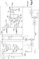
- the voltage converter will be better understood by referring to the figure 2 .
- the converter 1 comprises an isolated DC / DC converter circuit 3 and a circuit 2 for regulating the input voltage of the isolated DC / DC converter circuit 3.
- the circuits 2, 3 include switches M21, M22, M31, M32, one of which succession of openings and closings make it possible to control the output signal of these circuits. These switches can be transistors, such as MOSFETs, IGBTs, or others.
- the circuits 2, 3 can be made from a semiconductor material such as silicon (Si), gallium nitride (GaN), silicon carbide (SiC), or any other semiconductor material.
- the regulation circuit 2 is a step-down DC / DC converter, however it could be of another type of DC / DC converter as illustrated in figures 3 and 4 .
- the regulation circuit 2 comprises two switches M21, M22 in series.
- Switch M21 called the high side switch, is connected to the high terminal of a voltage source (not shown).
- Switch M22 called a low side switch, is connected to the low terminal of the voltage source. This low terminal corresponds in particular to a first ground GND1 of the converter 1.
- Each switch M21, M22 can comprise a transistor in parallel with a freewheeling diode.
- Each switch M21, M22 comprises a capacitor C21, C22 in parallel. These capacitors C21, C22 are used to make a zero voltage switching or ZVS (for “Zero Voltage Switching” in English) when the switches are opened. During the opening of a switch M21, M22, the energy stored in an inductor is recovered to discharge and recharge the capacitor C21, C22 which is at the terminals of the switch. Once the voltage is close to 0V, the switch is commanded and thus switching is carried out under voltage zero, which greatly reduces switching losses.
- ZVS Zero Voltage Switching
- An inductor L2 has a first terminal connected to the midpoint of the two switches M21, M22, and a second terminal connected to the input of the isolated DC / DC converter circuit 3.
- a capacitor C1 is connected between the second terminal of the inductor L2 and the first ground GND1 of the converter 1. This capacitor C1 makes it possible for example to form the interface between the circuits 2, 3.
- the isolated DC / DC converter circuit 3 comprises two switches M31, M32 in series, preferably identical.
- Switches M31, M32 include diodes and capacitors C31, C32 similar to diodes and capacitors C21, C22 described above for switches M21, M22.
- the midpoint between the two switches M31, M32 is connected to a branch which includes two isolation transformers T1, T2 in series.
- Each transformer T1, T2 comprises a primary L11, L21 and a secondary L12, L22.
- the primaries L11, L21 and the secondaries L12, L22 are respectively in series.
- the midpoint of switches M31, M32 is connected to primaries L11, L21.
- a capacitor C33 is between the transformers T1, T2 and the first ground GND1.
- the secondaries L12, L22 are in series with their midpoint connected to a second ground GND2 of the voltage converter 1.
- Diodes D31, D32 are connected to the secondaries L12, L22 to rectify the signal coming from the transformers T1, T2.
- a diode D31 has its anode connected to a terminal of a secondary L12 and the other diode D32 has its anode connected to a terminal of the other secondary L22, these terminals being different from the midpoint of the two secondaries L12 , L22.
- the diodes D31, D32 could advantageously be replaced by switches, in particular transistors, such as MOSFET, IGBT or other transistors, in order for example to obtain synchronous rectification at the output of transformers T1, T2.
- MOSFETs instead of diodes improves the overall efficiency of converter 1.
- the output of the isolated DC / DC converter circuit 3 is taken between the terminal of the diodes D31, D32 which is not connected to the secondaries L12, L22 and which is common to the two diodes D31, D32 and the second ground GND2.
- the voltage converter 1 comprises a capacitor CF for filtering the signal delivered by the isolated DC / DC converter circuit 3.
- the switches M31, M32 of the isolated DC / DC converter circuit 3 have a duty cycle which makes it possible to transfer energy through the transformers T1, T2.
- switch M31 is closed and switch M32 is open.
- the primary L11 of the first transformer T1 produces an inductance allowing gentle switching of the switches M31, M32 and the primary L21 of the second transformer T2 transfers energy to the secondary L22 of the second transformer T2.
- the primary L21 of the second transformer T2 produces an inductance allowing gentle switching of the switches M31, M32, and the primary L11 of the first transformer T1 transfers energy to the secondary L12 of the first transformer T1.
- the durations of the first and second operating parts are defined by the duty cycle ⁇ of the switches M31, M32.
- the switches M31, M32 operate with a duty cycle ⁇ which does not vary, that is to say which remains constant over time.
- the output voltage Vout of the isolated DC / DC converter circuit 3 is controlled by the voltage delivered by the regulation circuit 2, that is to say at the input of the isolated DC / DC converter circuit 3.
- the converter 1 comprises a control unit 5 of the regulation circuit 2.
- the control unit 5 delivers a pulse width modulation signal S2 or PWM (for "puise width modulation" in English) which controls the opening and the closing of the switches M21, M22 of the regulation circuit 2 to control the electrical signal delivered by the regulation circuit 2.
- the switches M21, M22 are controlled so that the voltage delivered at the input of the isolated DC / DC converter circuit 3, that is to say at the output of the regulation circuit 2, makes it possible to obtain a desired voltage value at the output of the isolated DC / DC converter circuit 3.
- the isolated DC / DC converter circuit 3 can therefore operate at its most advantageous duty cycle, in particular at 50%.
- the cyclic ratio ⁇ is preferably equal to 50%.
- the voltage stresses at the terminals of two diodes D31, D32 are equal, the wear is the same between the diodes.
- the current ripples due to the magnetizing inductances of transformers T1, T2 are compensated with each other.
- the current at the secondaries L12, L22 is continuous.
- the magnetizing inductances of the transformers T1, T2 are such that at a constant duty cycle, equal in particular to 50%, a magnetizing current flowing in the transformers T1, T2 allows gentle switching of the switches M31, M32 of the DC / DC converter isolated 3.
- the regulation circuit 2 makes it possible to ensure that the voltage U at the input of the isolated DC / DC converter circuit 3 keeps a value which makes it possible to obtain the desired output voltage Vout.
- the control unit 5 correspondingly modifies the control of the duty cycles of the switches M21, M22 to maintain the voltage U at the output of the regulation circuit 2, c 'that is to say at the input of the isolated DC / DC converter 3. This is particularly advantageous in an electric vehicle where the charge level of a battery can vary over time.
- control unit 5 carries out a first loop for slaving the current delivered by the regulation circuit 2 to a difference between the value Vout_mes of the output voltage of the isolated DC / DC converter circuit 3 and a desired voltage Vout at the output of the isolated DC / DC converter circuit 3.
- the control unit 5 receives the voltage Vout_mes measured at the output of the isolated DC / DC converter circuit 3, optionally multiplied by a gain K1.
- the unit of command 5 then compares a voltage setpoint V * with the voltage Vout mes measured.
- the voltage setpoint V * corresponds to the desired voltage Vout at the output of the isolated DC / DC converter circuit 3.
- a controller 51 delivers a current setpoint I2cons to the regulation circuit 2 so as to obtain a voltage U expected at the output of the regulation circuit 2, that is to say at the input of the isolated DC / DC converter circuit 3.
- the current setpoint I2cons is such that the regulation circuit 2 delivers to the isolated DC / DC converter circuit 3 the input voltage value U corresponding to the respective voltage value Vout expected at the output of the isolated DC / DC converter circuit 3.
- the first servo loop could be produced by any other means.
- the first loop could directly control the voltage U delivered by the regulation circuit 2.
- the control unit 5 can additionally provide protection for the isolated DC / DC converter circuit 3. For example, in the event of a short circuit at the output load Rout, the control unit 5 can protect the converter circuit. Isolated DC / DC 3 by acting on the controls S2 of the regulation circuit 2 so as to cancel the input voltage of the isolated DC / DC converter circuit 3 in order to protect it.
- the current setpoint I2cons can be transmitted directly to a controller 52 which delivers to the regulation circuit 2 the PWM signal S2 from the current setpoint I2cons.
- the control unit 5 can produce a second loop which slaves the current delivered by the regulation circuit 2 to a difference between the value I2mes of the current delivered by the regulation circuit 2 and the current setpoint I2cons.
- the control unit 5 compares the current setpoint I2cons resulting from the first loop with the current I2mes measured at the output of the regulation circuit 2.
- the current I2 cons is optionally multiplied by a gain K2 before the comparison.
- the controller 52 determines the signal S2 for controlling the duty cycle of the switches M21, M22 of the regulation circuit 2, so as to adjust the current delivered by the regulation circuit 2 to obtain the expected current I2cons ; and thus obtain a signal having the voltage U expected at the output of the regulation circuit 2, that is to say at the input of the isolated DC / DC converter circuit 3.
- the second servo loop could be produced by any other means allowing to obtain, at the output of the regulation circuit 2, the voltage U in order to reach the voltage Vout at the output of the isolated DC / DC converter circuit 3.
- a voltage loop could be used.
- the current loop is easier to implement because, in small signal, the current loop makes it possible to have a transfer function of the first order while the voltage loop is of the second order. Further, the voltage converter 1 could implement the first loop without using the second loop.
- the converter 1 can be designed to cover an operating range.
- the operating range corresponds to an input voltage Ue of converter 1 between a minimum value Ue min1 and a maximum value Ue max1 ; and at an output voltage Vout between a minimum value Vout min1 and a maximum value Vout max1 .
- the input voltage Ue is between 170 and 450V; and the target voltage Vout at the output of the isolated DC / DC converter circuit is between 12 and 16V.
- the minimum value Vout min1 of the output voltage is between 8 and 14V and the maximum value Vout max1 of the output voltage is between 15 and 16V.
- the regulation circuit 2 is a step-down converter.
- the converter 1, in particular the regulation circuit 2 is then configured to be able to deliver the maximum output voltage Vout max1 with the minimum voltage Ue min1 .
- the figure 3 illustrates an example of a converter in which the regulation circuit 2 is a step-up circuit known per se.
- the converter 1, in particular the regulation circuit 2 is then configured to be able to deliver the minimum output voltage Vout min1 with the maximum input voltage Ue max1 .
- the figure 4 illustrates another example of a converter in which the regulation circuit 2 is a step-up-step circuit known per se.
- the regulation circuit 2 can lower or raise the voltage, which facilitates the use of the regulation circuit 2.
- the output of the regulation circuit 2 is connected to the isolated DC / DC converter circuit 3 at the level of the branch of the isolated DC / DC converter circuit 3 which comprises the switches M31, M32.
- diodes D31, D32 are replaced by switches; and the high output is connected to the midpoint of the secondaries L12, L22, while in the previous examples, the high output is connected to the common terminal of the diodes D31, D32.
- the examples shown in figures 5 to 7 could be identical to the examples of figures 2 to 4 with regard to these characteristics.
- the examples of converters 1 can be configured to operate, on a first operating range of converter 1, with a duty cycle of the isolated DC / DC converter circuit 3 which is constant and, on a second operating range of converter 1, with a duty cycle which is variable. This is particularly advantageous for obtaining an input voltage range Ue and / or an output voltage range Vout which are larger compared to an operation in which the duty cycle of the isolated DC / DC converter circuit is always constant.
- a graph represents the gain G of the isolated DC / DC converter circuit 3 of the converter 1 illustrated in figure 3 , as a function of the duty cycle ⁇ of the isolated DC / DC converter circuit 3.
- the gain G corresponds to the ratio between the voltage Vout at the output of the isolated DC / DC converter circuit 3 on the voltage U at the input of the isolated DC / DC converter circuit 3.
- the isolated DC / DC converter circuit 3 operates with a constant duty cycle equal to 0.5.
- the operating range defined above corresponds to the first operating range. If it is desired to reach values outside the first operating range, the duty cycle ⁇ of the isolated DC / DC converter circuit 3 can be modified to reach the desired value.
- the converter 1 has a total operating range which is extended compared to the embodiments described above.
- the input voltage Ue is between 170 and 450V; and the target voltage Vout at the output of the isolated DC / DC converter circuit 3 is between 12 and 16V.
- the second operating range is defined by a lower threshold Ue min2 of input voltage equal to 450V and by an upper threshold Vout max2 of output voltage equal to 12V. If, when the input voltage is equal to 450V, one wishes to reach a target value of output voltage lower than 12V, for example 9V, the target value cannot be reached by changing the duty cycle of regulation circuit 2 because circuit 2 is a step-up converter which can only raise the input voltage Ue.
- the duty cycle ⁇ of the isolated DC / DC converter circuit 3 can be reduced to a value lower al lower than 0.5 or to a value ⁇ 2 higher than 0.5.
- Converters 1 can be put in parallel and intertwined in order to limit the current ripples at the output and reduce the value of the filtering capacitance CF at the output of the isolated DC / DC converter circuit 3.
- the duty cycle ⁇ of the isolated DC / DC converter circuit 3 remains constant.
- the duty cycle ⁇ of the isolated DC / DC converter circuit 3 remains constant over a first part of the operating range and varies over a second part of the operating range as described above.
- the figure 9 illustrates an operation of a conversion device 10 which comprises an interleaving of converters 1.
- the first servo loop is common to all the converters 1.
- the regulation circuits 2 receive the same current setpoint I2cons.
- the device 10 can include a single controller 51 delivering a single current setpoint I2cons to all regulation circuits 2. Thus, current balancing between voltage converters 1 is ensured.
- the converters 1 operate with a phase shift.
- the regulation circuits 2 operate with a phase shift of 2 ⁇ / n, where n is the number of interlaced converters 1, which makes it possible to limit the fluctuations at the output of the device 10 and the problems of electromagnetic compatibility.
- the isolated DC / DC converter circuits 3 operate with a phase shift of ⁇ / n which makes it possible to limit the ripples at the output of the device 10.
- the invention is not limited to the examples described.
- the voltage loops can be replaced by current loops, conversely the current loops can be replaced by voltage loops.
- the isolated DC / DC converter circuit 3 has been described with a half-bridge structure.
- the isolated DC / DC converter circuit 3 could have a full bridge structure, or any other structure allowing the performance of the isolated DC / DC converter function.
- isolated DC / DC converters are similar to those previously described except for the following difference.
- the primary L11 of the first transformer T1 produces an inductance storing energy and the primary L21 of the second transformer T2 transfers energy to the secondary L22 of the second transformer T2.
- the primary L21 of the second transformer T2 produces an inductance storing energy, and the primary L11 of the first transformer T1 transfers energy to the secondary L12 of the first transformer T1.
- a magnetizing current flowing in the transformers T1, T2 does not necessarily allow gentle switching of the switches M31, M32 of the isolated DC / DC converter.
Landscapes
- Engineering & Computer Science (AREA)
- Power Engineering (AREA)
- Dc-Dc Converters (AREA)
Description
- La présente invention concerne un convertisseur de tension comprenant un circuit convertisseur DC/DC isolé, un dispositif de conversion de tension comprenant un entrelacement de convertisseurs selon l'invention, ainsi qu'un procédé de conversion de tension mis en œuvre avec le convertisseur selon l'invention.
- Les convertisseurs DC/DC (pour « direct current/direct current » en anglais) isolés peuvent présenter des commutations à zéro de tension ou ZVS (pour « zero voltage switching » en anglais) ou des commutations à zéro de courant ou ZCS (pour « zero current switching » en anglais) qui permettent de réduire les pertes par commutation lors de la conversion de tension. Ces convertisseurs sont donc particulièrement avantageux dans une application automobile où la ressource en énergie est limitée. Dans un véhicule, on peut utiliser un convertisseur de tension pour adapter des niveaux de tension entre plusieurs réseaux électriques du véhicule ou pour convertir une tension entre une source d'énergie et un consommateur électrique embarqué dans le véhicule.
- On connaît un convertisseur selon le préambule de la revendication 1 du brevet
US5274539 . - On connait un convertisseur de tension DC/DC isolé du brevet
US5754413 , illustré enfigure 1 . Le convertisseur comprend deux interrupteurs, agencés en demi-pont, qui sont connectés en leur point milieu à une branche qui comprend deux transformateurs en série. Les interrupteurs contrôlent la transmission d'énergie à travers les transformateurs pour obtenir une conversion d'une tension d'entrée du convertisseur en une tension de sortie. Des diodes connectées aux secondaires des transformateurs permettent de redresser le signal de sortie. La tension de sortie est obtenue en contrôlant le rapport cyclique des interrupteurs. En modifiant le rapport cyclique pour atteindre une valeur cible de tension de sortie, on ajuste le gain du convertisseur pour atteindre la valeur cible de tension de sortie. En particulier, lorsque la tension d'entrée du convertisseur DC/DC isolé varie, il est connu de faire varier le rapport cyclique des interrupteurs du convertisseur DC/DC isolé pour réguler sa tension de sortie, c'est-à-dire maintenir sa tension de sortie à une valeur souhaitée. - Cependant, le stress en tension des diodes de redressement est fonction du rapport cyclique des interrupteurs du convertisseur. Ce stress peut devenir important lorsque le rapport cyclique devient proche de 0% ou 100%. Pour limiter le stress en tension des diodes de redressement, il est prévu, pour les deux transformateurs, des rapports de transformations respectifs qui sont différents. Mais cela complique la conception du convertisseur car les transformateurs ne peuvent pas être identiques et le courant au secondaire présente des discontinuités.
- En outre, en travaillant avec un rapport cyclique variable, les ondulations de courant en sortie peuvent varier fortement entrainant une variation du rendement du convertisseur. Pour conserver un fonctionnement avec un bon rendement, le rapport cyclique doit être peu variable. Or, dans un véhicule, la tension d'une source d'énergie, telle qu'une batterie, peut varier fortement suivant l'énergie disponible. Une telle variation en entrée du convertisseur implique de faire varier le rapport cyclique de manière correspondante, ce qui limite l'utilisation du convertisseur DC/DC isolé dans un véhicule.
- Il est donc recherché une solution pour améliorer les performances d'un convertisseur DC/DC isolé de façon à permettre son utilisation dans un véhicule automobile.
- Afin de résoudre ce problème, l'invention concerne un convertisseur selon la revendication 1.
- Grâce au circuit de régulation, une valeur souhaitée de tension en sortie du circuit convertisseur DC/DC isolé est obtenue en ajustant la tension appliquée au circuit convertisseur DC/DC isolé. A chaque valeur de tension souhaitée en sortie du circuit convertisseur DC/DC isolé correspond une valeur de tension appliquée au circuit convertisseur DC/DC isolé. Une valeur de tension de sortie souhaitée est obtenue sans modifier le rapport cyclique du circuit convertisseur DC/DC isolé. Le rapport cyclique peut donc être fixé à une valeur qui permet un rendement maximal.
- A une tension de sortie donnée du circuit convertisseur DC/DC isolé, le circuit de régulation permet un fonctionnement du circuit convertisseur DC/DC isolé avec un rapport cyclique constant pour une tension d'entrée quelconque, en particulier comprise dans une gamme de fonctionnement du circuit convertisseur DC/DC isolé.
- Par exemple, la différence entre la valeur minimale et la valeur maximale de la tension d'entrée du convertisseur est comprise entre 150 et 500V ; par exemple, la valeur minimale de la tension d'entrée est comprise entre 150 et 200 V; et la valeur maximale de la tension d'entrée est comprise entre 400 et 500V, voire entre 400 et 650V.
- Le rapport cyclique des interrupteurs du circuit convertisseur DC/DC isolé reste donc constant à une incertitude près.
- En particulier, le circuit de régulation comprend des interrupteurs et est tel que son rapport cyclique est ajusté pour obtenir une valeur de tension en sortie du circuit de régulation. Cette valeur de tension est ajustée pour obtenir une valeur de tension souhaitée en sortie du circuit convertisseur DC/DC isolé.
- Le circuit de régulation délivre son signal de sortie au circuit convertisseur DC/DC isolé.
- Notamment, le circuit de régulation est configuré pour délivrer une tension au circuit convertisseur DC/DC isolé à partir, directement ou indirectement, d'une tension d'entrée du convertisseur de tension.
- Le convertisseur de tension peut être un convertisseur continu-continu configuré pour convertir une tension d'entrée continue en une tension de sortie continue.
- Le convertisseur de tension peut être un convertisseur alternatif-continu configuré pour convertir une tension alternative en une tension continue. Avantageusement, le convertisseur de tension comprend alors un circuit convertisseur alternatif-continu en amont du circuit de régulation ou un circuit convertisseur continu-alternatif en aval du circuit convertisseur DC/DC isolé. Par des adaptations adéquates, le convertisseur de tension peut être un convertisseur alternatif-alternatif.
- Selon un mode de réalisation, le circuit convertisseur DC/DC isolé est configuré de sorte que son rapport cyclique est sensiblement égal à 50%. A un rapport cyclique de 50%, le courant en sortie du circuit convertisseur DC/DC isolé présente des ondulations (« ripples » en anglais) qui sont faibles car les ondulations des courants dans des inductances magnétisantes du circuit convertisseur DC/DC isolé sont compensées.
- Selon un mode de réalisation, le circuit de régulation et le circuit convertisseur DC/DC isolé sont dans un seul module. En particulier, le circuit de régulation et le circuit convertisseur DC/DC isolé sont dans un même boitier d'un module électronique ou sur une même carte électronique du module.
- Selon un mode de réalisation, le convertisseur comprend un circuit destiné à implémenter une première boucle de façon à asservir une consigne d'un paramètre électrique d'un signal du circuit de régulation à une différence entre la valeur de la tension de sortie du circuit convertisseur DC/DC isolé et une consigne de tension de sortie du circuit convertisseur DC/DC isolé, la consigne du paramètre électrique étant telle que le circuit de régulation délivre au circuit convertisseur DC/DC isolé une valeur de tension correspondant à une valeur respective de tension de sortie du circuit convertisseur DC/DC isolé.
- Selon une variante, le convertisseur comprend un circuit destiné à implémenter une deuxième boucle de façon à asservir le paramètre électrique du signal du circuit de régulation à une différence entre la valeur du paramètre électrique et la consigne du paramètre électrique.
- Selon une variante, le signal du circuit de régulation est le signal délivré par le circuit de régulation, ou un signal circulant dans le circuit de régulation.
- Selon une variante, le paramètre électrique du signal est son courant ou sa tension.
- Ainsi, dans une variante, le circuit est destiné à implémenter la première boucle de façon à asservir le courant délivré par le circuit de régulation, ou un courant circulant dans le circuit de régulation, à une différence entre la valeur de la tension de sortie du circuit convertisseur DC/DC isolé et une consigne de tension de sortie du circuit convertisseur DC/DC isolé.
- En particulier, le circuit de la première boucle et/ou de la seconde boucle asservissent le paramètre électrique en asservissant des interrupteurs compris dans le circuit de régulation, notamment en asservissant un rapport cyclique d'ouverture ou de fermeture des interrupteurs.
- Selon un mode de réalisation, le circuit de régulation est un convertisseur DC/DC de type sepic (pour l'anglais « Single Ended Primary Inductor Converter »), Ćuk, abaisseur (« buck » en anglais), élévateur (« boost » en anglais) ou abaisseur-élévateur (« buck-boost » en anglais).
- Selon un mode de réalisation, le circuit convertisseur DC/DC isolé comprend au moins un premier et un deuxième transformateurs d'isolation en série, les interrupteurs permettant de transmettre une énergie à travers le convertisseur DC/DC isolé par l'intermédiaire des transformateurs.
- Selon un mode de réalisation, le circuit convertisseur DC/DC est configuré pour que :
- sur une première partie d'une période de fonctionnement, le primaire du premier transformateur réalise une inductance stockant de l'énergie et le primaire du second transformateur transfère une énergie vers le secondaire du second transformateur ;
- sur une deuxième partie de la période de fonctionnement, le primaire du second transformateur réalise une inductance stockant de l'énergie, et le primaire du premier transformateur transfère une énergie vers le secondaire du premier transformateur.
- Selon un mode de réalisation, le circuit convertisseur DC/DC est configuré pour que :
- sur une première partie d'une période de fonctionnement, le primaire du premier transformateur réalise une inductance permettant une commutation douce des interrupteurs et le primaire du second transformateur transfère une énergie vers le secondaire du second transformateur ;
- sur une deuxième partie de la période de fonctionnement, le primaire du second transformateur réalise une inductance permettant une commutation douce des interrupteurs, et le primaire du premier transformateur transfère une énergie vers le secondaire du premier transformateur.
- Selon un mode de réalisation, une inductance magnétisante d'au moins un transformateur est configurée de sorte qu'audit rapport cyclique un courant magnétisant circulant dans le transformateur permette une commutation douce des interrupteurs du convertisseur DC/DC isolé.
- La sortie du circuit de régulation est connectée à une branche du circuit convertisseur DC/DC isolé comprenant lesdits transformateurs.
- Selon un mode de réalisation, les interrupteurs et les primaires du circuit convertisseur DC/DC isolé forment une structure en demi-pont. Alternativement, les interrupteurs et les primaires du circuit convertisseur DC/DC isolé forment une structure en pont complet, ou ont toute autre configuration permettant un fonctionnement du circuit convertisseur DC/DC isolé.
- Selon un mode de réalisation, au moins un des interrupteurs comprend une capacité en parallèle.
- Selon un mode de réalisation, le rapport cyclique du circuit convertisseur DC/DC isolé est sensiblement égal à 50%.
- Selon un mode de réalisation, le contrôle de la tension de sortie du circuit convertisseur DC/DC isolé comprend une première boucle asservissant la consigne d'un paramètre électrique d'un signal du circuit de régulation à une différence entre la valeur de la tension de sortie du circuit convertisseur DC/DC isolé et une consigne de tension de sortie du circuit convertisseur DC/DC isolé, la consigne du paramètre électrique étant telle que le circuit convertisseur DC/DC isolé reçoit une tension ayant une valeur correspondant à une valeur respective de tension de sortie du circuit convertisseur DC/DC isolé.
- Selon un mode de réalisation, le procédé comprend la fourniture du circuit convertisseur DC/DC isolé comprenant au moins un premier et un deuxième transformateurs d'isolation en série ; et :
- sur une première partie d'une période de fonctionnement du circuit convertisseur DC/DC isolé, le primaire du premier transformateur réalise une inductance stockant de l'énergie et le primaire du second transformateur transfère une énergie vers le secondaire du second transformateur ;
- sur une deuxième partie de la période de fonctionnement du circuit convertisseur DC/DC isolé, le primaire du second transformateur réalise une inductance stockant de l'énergie, et le primaire du premier transformateur transfère une énergie vers le secondaire du premier transformateur.
- Selon un mode de réalisation, le procédé comprend la fourniture du circuit convertisseur DC/DC isolé comprenant au moins un premier et un deuxième transformateurs d'isolation en série ; et :
- sur une première partie d'une période de fonctionnement du circuit convertisseur DC/DC isolé, le primaire du premier transformateur réalise une inductance permettant une commutation douce des interrupteurs et le primaire du second transformateur transfère une énergie vers le secondaire du second transformateur ;
- sur une deuxième partie de la période de fonctionnement du circuit convertisseur DC/DC isolé, le primaire du second transformateur réalise une inductance permettant une commutation douce des interrupteurs, et le primaire du premier transformateur transfère une énergie vers le secondaire du premier transformateur.
- Le contrôle de la tension de sortie du circuit convertisseur DC/DC isolé comprend la modification d'une tension délivrée par le circuit de régulation au niveau d'une branche du circuit convertisseur DC/DC isolé comprenant les transformateurs du circuit convertisseur DC/DC isolé.
- Selon un mode de réalisation, le procédé comprend la fourniture d'une pluralité de convertisseurs DC/DC isolés entrelacés ; et :
- les circuits convertisseurs DC/DC isolés fonctionnent avec un déphasage de π/n, n étant le nombre de convertisseurs entrelacés ; et
- le ou les circuits de régulation fonctionnent avec un déphasage de 2π/n.
- Selon un mode de réalisation, le contrôle de la tension de sortie des circuits DC/DC isolés est réalisé avec la même consigne délivrée par un seul circuit de régulation.
- L'invention concerne aussi un procédé de conversion de tension comprenant les étapes consistant à :
- fournir au moins un circuit convertisseur DC/DC isolé ayant des interrupteurs dont des successions d'ouverture et de fermeture avec au moins un rapport cyclique permettent de transmettre une énergie à travers le convertisseur DC/DC isolé ; au moins un premier transformateur d'isolation ; et un circuit de régulation de la tension d'entrée du circuit convertisseur DC/DC isolé ;
- contrôler la tension de sortie du circuit convertisseur DC/DC isolé en modifiant la tension délivrée au circuit convertisseur DC/DC isolé, le rapport cyclique du circuit convertisseur DC/DC isolé restant constant, la dite étape comprenant la modification d'une tension délivrée par le circuit de régulation au niveau d'une branche du circuit convertisseur DC/DC isolé comprenant le premier transformateur du circuit convertisseur DC/DC isolé.
- Le procédé selon cette invention peut comprendre l'une quelconque des étapes décrites précédemment et qui lui sont compatibles.
- L'invention sera mieux comprise en faisant référence aux dessins, dans lesquels :
- la
figure 1 illustre un exemple de convertisseur de tension DC/DC isolé selon l'art antérieur ; - les
figures 2 à 7 illustrent chacune un exemple de convertisseur de tension DC/DC; - la
figure 8 représente un graphe du gain en fonction du rapport cyclique dans un convertisseur de tension DC/DC isolé - la
figure 9 illustre un exemple de procédé de commande d'un dispositif de conversion comprenant un entrelacement de convertisseurs. - Le convertisseur de tension sera mieux compris en faisant référence à la
figure 2 . - Le convertisseur 1 comprend un circuit convertisseur DC/DC isolé 3 et un circuit 2 de régulation de la tension d'entrée du circuit convertisseur DC/DC isolé 3. Les circuits 2, 3 comprennent des interrupteurs M21, M22, M31, M32 dont une succession d'ouvertures et de fermetures permettent de contrôler le signal de sortie de ces circuits. Ces interrupteurs peuvent être des transistors, tels que des transistors MOSFET, IGBT, ou autres. Les circuits 2, 3 peuvent être réalisés à partir d'un matériau semiconducteur tel que du silicium (Si), du nitrure de gallium (GaN), du carbure de silicium (SiC), ou tout autre matériau semiconduteur.
- Dans l'exemple considéré, qui ne fait pas partie de l'invention revendiquée, le circuit de régulation 2 est un convertisseur DC/DC abaisseur, cependant il pourrait être d'un autre type de convertisseur DC/DC comme illustré en
figures 3 et4 . Le circuit de régulation 2 comprend deux interrupteurs M21, M22 en série. L'interrupteur M21, dit interrupteur côté haut, est connecté à la borne haute d'une source de tension (non représentée). L'interrupteur M22, dit interrupteur côté bas, est connecté à la borne basse de la source de tension. Cette borne basse correspond notamment à une première masse GND1 du convertisseur 1. Chaque interrupteur M21, M22, peut comprendre un transistor en parallèle avec une diode de roue libre. - Chaque interrupteur M21, M22 comprend une capacité C21, C22 en parallèle. Ces capacités C21, C22 servent à faire une commutation à zéro de tension ou ZVS (pour « Zero Voltage Switching » en anglais) lors de l'ouverture des interrupteurs. Pendant l'ouverture d'un interrupteur M21, M22 on récupère l'énergie stockée dans une inductance pour décharger et recharger la capacité C21, C22 qui est aux bornes de l'interrupteur. Une fois que la tension est proche de 0V on vient commander l'interrupteur et ainsi on réalise une commutation sous zéro de tension, ce qui réduit fortement les pertes en commutation.
- Une inductance L2 a une première borne connectée au point milieu des deux interrupteurs M21, M22, et une deuxième borne connectée à l'entrée du circuit convertisseur DC/DC isolé 3.
- Une capacité C1 est connectée entre la deuxième borne de l'inductance L2 et la première masse GND1 du convertisseur 1. Cette capacité C1 permet par exemple de faire l'interface entre les circuits 2,3.
- Le circuit convertisseur DC/DC isolé 3 comprend deux interrupteurs M31, M32 en série, de préférence identiques. Les interrupteurs M31, M32 comprennent des diodes et des capacités C31, C32 similaires aux diodes et aux capacités C21, C22 décrites précédemment pour les interrupteurs M21, M22. Le point milieu entre les deux interrupteurs M31, M32 est connecté à une branche qui comprend deux transformateurs d'isolation T1, T2 en série. Chaque transformateur T1, T2 comprend un primaire L11, L21 et un secondaire L12, L22. Les primaires L11, L21 et les secondaires L12, L22 sont respectivement en série. Le point milieu des interrupteurs M31, M32 est connecté aux primaires L11, L21. Une capacité C33 est comprise entre les transformateurs T1, T2 et la première masse GND1. Les secondaires L12, L22 sont en série avec leur point milieu connecté à une seconde masse GND2 du convertisseur de tension 1.
- Des diodes D31, D32 sont connectées au secondaires L12, L22 pour redresser le signal issu des transformateurs T1, T2. A cet effet, une diode D31 a son anode connectée à une borne d'un secondaire L12 et l'autre diode D32 a son anode connectée à une borne de l'autre secondaire L22, ces bornes étant différentes du point milieu des deux secondaires L12, L22. Les diodes D31, D32 pourraient être avantageusement remplacées par des interrupteurs, notamment des transistors, tels que des transistors MOSFET, IGBT ou autres, afin d'obtenir par exemple un redressement synchrone en sortie des transformateurs T1, T2. Pour des applications à fort courant au secondaire l'usage de MOSFET à la place des diodes permet d'améliorer le rendement global du convertisseur 1.
- La sortie du circuit convertisseur DC/DC isolé 3 est prise entre la borne des diodes D31, D32 qui n'est pas connectée aux secondaires L12, L22 et qui est commune aux deux diodes D31, D32 et la seconde masse GND2.
- Le convertisseur de tension 1 comprend une capacité CF pour filtrer le signal délivré par le circuit convertisseur DC/DC isolé 3.
- Les interrupteurs M31, M32 du circuit convertisseur DC/DC isolé 3 ont un rapport cyclique qui permet de transférer une énergie à travers les transformateurs T1, T2.
- Sur une première partie d'une période de fonctionnement, l'interrupteur M31 est fermé et l'interrupteur M32 est ouvert. Le primaire L11 du premier transformateur T1 réalise une inductance permettant une commutation douce des interrupteurs M31, M32 et le primaire L21 du second transformateur T2 transfère une énergie vers le secondaire L22 du second transformateur T2.
- Sur une deuxième partie de la période de fonctionnement, le primaire L21 du second transformateur T2 réalise une inductance permettant une commutation douce des interrupteurs M31, M32, et le primaire L11 du premier transformateur T1 transfère une énergie vers le secondaire L12 du premier transformateur T1. Les durées des première et deuxième parties de fonctionnement sont définies par le rapport cyclique α des interrupteurs M31, M32.
- Les interrupteurs M31, M32 fonctionnent avec un rapport cyclique α qui ne varie pas, c'est-à-dire qui reste constant au cours du temps. Lors du fonctionnement du convertisseur 1, la tension de sortie Vout du circuit convertisseur DC/DC isolé 3 est contrôlée par la tension délivrée par le circuit de régulation 2, c'est-à-dire en entrée du circuit convertisseur DC/DC isolé 3. A cet effet, le convertisseur 1 comprend une unité de commande 5 du circuit de régulation 2. L'unité de commande 5 délivre un signal S2 de modulation en largeur d'impulsion ou PWM (pour « puise width modulation » en anglais) qui commande l'ouverture et la fermeture des interrupteurs M21, M22 du circuit de régulation 2 pour contrôler le signal électrique délivré par le circuit de régulation 2. Les interrupteurs M21, M22 sont commandés de sorte que la tension délivrée en entrée du circuit convertisseur DC/DC isolé 3, c'est-à-dire en sortie du circuit de régulation 2, permette d'obtenir une valeur de tension souhaitée en sortie du circuit convertisseur DC/DC isolé 3. Ainsi, contrairement à l'art antérieur, il n'est pas nécessaire de faire varier le rapport cyclique α du circuit convertisseur DC/DC isolé 3. Le circuit convertisseur DC/DC isolé 3 peut donc fonctionner à son rapport cyclique le plus avantageux, notamment à 50%.
- Les stress en tension aux bornes des diodes D31, D32 sont fonction du rapport cyclique a, et sont donnés par les expressions suivantes :


- Le rapport cyclique α est de préférence égal à 50%. Ainsi, les stress en tension aux bornes de deux diodes D31, D32 sont égaux, l'usure est la même entre les diodes. En outre, à un rapport cyclique de 50%, les ondulations de courant dues aux inductances magnétisantes des transformateurs T1,T2 sont compensées entre elles. Ainsi, le courant aux secondaires L12, L22 est continu.
- Plus particulièrement, les inductances magnétisantes des transformateurs T1, T2 sont telles qu'au rapport cyclique constant, égal notamment à 50%, un courant magnétisant circulant dans les transformateurs T1, T2 permette une commutation douce des interrupteurs M31, M32 du convertisseur DC/DC isolé 3.
- En particulier, lorsque la tension d'entrée Ue du convertisseur de tension 1 varie, le circuit de régulation 2 permet de s'assurer que la tension U en entrée du circuit convertisseur DC/DC isolé 3 garde une valeur qui permet d'obtenir la tension de sortie Vout désirée. Ainsi, si la tension d'entrée Ue du convertisseur 1 change de valeur, l'unité de commande 5 modifie de façon correspondante la commande des rapports cycliques des interrupteurs M21, M22 pour maintenir la tension U en sortie du circuit de régulation 2, c'est-à-dire en entrée du convertisseur DC/DC isolé 3. Ceci est particulièrement avantageux dans un véhicule électrique où le niveau de charge d'une batterie peut varier au cours du temps.
- Plus particulièrement, l'unité de commande 5 réalise une première boucle d'asservissement du courant délivré par le circuit de régulation 2 à une différence entre la valeur Vout_mes de la tension de sortie du circuit convertisseur DC/DC isolé 3 et une tension Vout souhaitée en sortie du circuit convertisseur DC/DC isolé 3. A cet effet, l'unité de commande 5 reçoit la tension Vout_mes mesurée en sortie du circuit convertisseur DC/DC isolé 3, éventuellement multipliée par un gain K1. L'unité de commande 5 compare ensuite une consigne de tension V* avec la tension Vout mes mesurée. La consigne de tension V* correspond à la tension Vout souhaitée en sortie du circuit convertisseur DC/DC isolé 3. En fonction du résultat de la comparaison, un contrôleur 51 délivre une consigne de courant I2cons au circuit de régulation 2 de façon à obtenir une tension U attendue en sortie du circuit de régulation 2, c'est-à-dire en entrée du circuit convertisseur DC/DC isolé 3. La consigne de courant I2cons est telle que le circuit de régulation 2 délivre au circuit convertisseur DC/DC isolé 3 la valeur de tension d'entrée U correspondant à la valeur de tension Vout respective attendue en sortie du circuit convertisseur DC/DC isolé 3.
- La première boucle d'asservissement pourrait être réalisée par tout autre moyen. Par exemple, la première boucle pourrait asservir directement la tension U délivrée par le circuit de régulation 2.
- L'unité de commande 5 peut assurer en outre une protection du circuit convertisseur DC/DC isolé 3. Par exemple, en cas de court-circuit au niveau de la charge de sortie Rout, l'unité de commande 5 peut protéger le circuit convertisseur DC/DC isolé 3 en agissant sur les commandes S2 du circuit de régulation 2 de manière à annuler la tension en entrée du circuit convertisseur DC/DC isolé 3 afin de le protéger.
- La consigne de courant I2cons peut être transmise directement à un contrôleur 52 qui délivre au circuit de régulation 2 le signal PWM S2 à partir de la consigne de courant I2cons. Cependant, l'unité de commande 5 peut réaliser une deuxième boucle qui asservit le courant délivré par le circuit de régulation 2 à une différence entre la valeur I2mes du courant délivré par le circuit de régulation 2 et la consigne de courant I2cons. En particulier, l'unité de commande 5 compare la consigne de courant I2cons issue de la première boucle avec le courant I2mes mesuré en sortie du circuit de régulation 2. Le courant I2 cons est éventuellement multiplié par un gain K2 avant la comparaison. En fonction du résultat de cette comparaison, le contrôleur 52 détermine le signal S2 de commande du rapport cyclique des interrupteurs M21, M22 du circuit de régulation 2, de façon à ajuster le courant délivré par le circuit de régulation 2 pour obtenir le courant I2cons attendu ; et ainsi obtenir un signal ayant la tension U attendue en sortie du circuit de régulation 2, c'est-à-dire en entrée du circuit convertisseur DC/DC isolé 3. La deuxième boucle d'asservissement pourrait être réalisée par tout autre moyen permettant d'obtenir, en sortie du circuit de régulation 2, la tension U afin d'atteindre la tension Vout en sortie du circuit convertisseur DC/DC isolé 3. En particulier, une boucle de tension pourrait être utilisée. Cependant, la boucle de courant est plus facile à mettre en œuvre car, en petit signal, la boucle de courant permet d'avoir une fonction de transfert du premier ordre alors que la boucle de tension est du deuxième ordre. En outre, le convertisseur de tension 1 pourrait mettre en œuvre la première boucle sans utiliser la deuxième boucle.
- Le convertisseur 1 selon l'exemple peut être conçu pour couvrir une gamme de fonctionnement. La gamme de fonctionnement correspond à une tension d'entrée Ue du convertisseur 1 comprise entre une valeur minimale Uemin1 et une valeur maximale Uemax1 ; et à une tension de sortie Vout comprise entre une valeur minimale Voutmin1 et une valeur maximale Voutmax1. Par exemple, la tension d'entrée Ue est comprise entre 170 et 450V ; et la tension cible Vout en sortie du circuit convertisseur DC/DC isolé est comprise entre 12 et 16V. Par exemple, la valeur minimale Voutmin1 de la tension de sortie est comprise entre 8 et 14V et la valeur maximale Voutmax1 de la tension de sortie est comprise entre 15 et 16V.
- Dans l'exemple de la
figure 2 , le circuit de régulation 2 est un convertisseur abaisseur. Le convertisseur 1, en particulier le circuit de régulation 2, est alors configuré pour pouvoir délivrer la tension de sortie maximale Voutmax1 avec la tension minimale Uemin1. - Les exemples de convertisseurs illustrés en
figures 3 et4 sont similaires à l'exemple de lafigure 2 mais diffèrent par le circuit de régulation 2. - La
figure 3 illustre un exemple de convertisseur dans lequel le circuit de régulation 2 est un circuit élévateur connu en soi. Le convertisseur 1, en particulier le circuit de régulation 2, est alors configuré pour pouvoir délivrer la tension de sortie minimale Voutmin1 avec la tension d'entrée maximale Uemax1. - La
figure 4 illustre un autre exemple de convertisseur dans lequel le circuit de régulation 2 est un circuit élévateur-abaisseur connu en soi. Dans cet exemple, le circuit de régulation 2 peut abaisser ou élever la tension, ce qui facilite l'utilisation du circuit de régulation 2. - Dans les exemples illustrés en
figures 2 à 4 , la sortie du circuit de régulation 2 est connectée au circuit convertisseur DC/DC isolé 3 au niveau de la branche du circuit convertisseur DC/DC isolé 3 qui comprend les interrupteurs M31, M32. - Les exemples de l'invention illustrés en
figures 5 à 7 , sont identiques aux exemples desfigures 2 à 4 si ce n'est que, dans lesfigures 5 à 6 , la sortie du circuit de régulation 2 est connectée à la branche du circuit convertisseur DC/DC isolé 3 qui comprend les transformateurs T1, T2. En particulier, le circuit de régulation 2 est connecté entre les transformateurs T1, T2 et la capacité C33. - En outre, les diodes D31, D32 sont remplacées par des interrupteurs ; et la sortie haute est connectée au point milieu des secondaires L12, L22, alors que dans les exemples précédents, la sortie haute est connectée à la borne commune des diodes D31, D32. Cependant, les exemples illustrés en
figures 5 à 7 pourraient être identiques aux exemples desfigures 2 à 4 en ce qui concerne ces caractéristiques. - Les exemples de convertisseurs 1 peuvent être configurés pour fonctionner, sur une première gamme de fonctionnement du convertisseur 1, avec un rapport cyclique du circuit convertisseur DC/DC isolé 3 qui est constant et, sur une deuxième gamme de fonctionnement du convertisseur 1, avec un rapport cyclique qui est variable. Ceci est particulièrement avantageux pour obtenir une plage de tension d'entrée Ue et/ou une plage de tension de sortie Vout qui sont plus grandes par rapport à un fonctionnement dans lequel le rapport cyclique du circuit convertisseur DC/DC isolé est toujours constant.
- En
figure 8 , un graphe représente le gain G du circuit convertisseur DC/DC isolé 3 du convertisseur 1 illustré enfigure 3 , en fonction du rapport cyclique α du circuit convertisseur DC/DC isolé 3. Le gain G correspond au rapport entre la tension Vout en sortie du circuit convertisseur DC/DC isolé 3 sur la tension U en entrée du circuit convertisseur DC/DC isolé 3. La relation entre le gain G et le rapport cyclique α est définie par :
- Par exemple, le circuit convertisseur DC/DC isolé 3 fonctionne avec un rapport cyclique constant égal à 0,5. La gamme de fonctionnement définie précédemment correspond à la première gamme de fonctionnement. Si l'on souhaite atteindre des valeurs hors de la première gamme de fonctionnement, le rapport cyclique α du circuit convertisseur DC/DC isolé 3 peut être modifié pour atteindre la valeur souhaitée. Ainsi, le convertisseur 1 a une gamme de fonctionnement totale qui est élargie par rapport aux modes de réalisations décrits précédemment.
- Par exemple, dans la première gamme de fonctionnement, la tension d'entrée Ue est comprise entre 170 et 450V ; et la tension cible Vout en sortie du circuit convertisseur DC/DC isolé 3 est comprise entre 12 et 16V. La deuxième gamme de fonctionnement est définie par un seuil inférieur Uemin2 de tension d'entrée égal à 450V et par un seuil supérieur Voutmax2 de tension de sortie égal à 12V. Si, lorsque la tension d'entrée est égale à 450V, l'on souhaite atteindre une valeur cible de tension de sortie inférieure à 12V, par exemple 9V, la valeur cible ne peut être atteinte en modifiant le rapport cyclique du circuit de régulation 2 car le circuit 2 est un convertisseur élévateur qui ne peut qu'élever la tension d'entrée Ue. Par contre, en modifiant le rapport cyclique α du circuit convertisseur DC/DC isolé, le gain du circuit convertisseur DC/DC isolé diminue, ce qui permet de diminuer la tension de sortie Vout du circuit convertisseur DC/DC isolé, et permet donc d'atteindre la valeur cible, par exemple 9V. A cet effet, le rapport cyclique α du circuit convertisseur DC/DC isolé 3 peut être diminué à une valeur inférieure al inférieure à 0,5 ou à une valeur α2 supérieure à 0,5.
- Pour des applications de puissance, il est avantageux d'entrelacer plusieurs des convertisseurs 1 illustrés en
figures 2 à 7 . On peut mettre des convertisseurs 1 en parallèle et les entrelacer afin de limiter les ondulations de courant en sortie et réduire la valeur de la capacité de filtrage CF en sortie du circuit convertisseur DC/DC isolé 3. Dans chaque convertisseur 1, grâce au circuit de régulation 2, le rapport cyclique α du circuit convertisseur DC/DC isolé 3 reste constant. Ou, dans chaque convertisseur 1, le rapport cyclique α du circuit convertisseur DC/DC isolé 3 reste constant sur une première partie de la gamme de fonctionnement et varie sur une deuxième partie de la gamme de fonctionnement comme décrit précédemment. - La
figure 9 illustre un fonctionnement d'un dispositif de conversion 10 qui comprend un entrelacement de convertisseurs 1. De préférence, la première boucle d'asservissement est commune à tous les convertisseurs 1. Ainsi, les circuits de régulation 2 reçoivent la même consigne de courant I2cons. A cet effet, le dispositif 10 peut comprendre un seul contrôleur 51 délivrant une seule consigne de courant I2cons à tous les circuits de régulation 2. Ainsi, un équilibrage en courant entre les convertisseurs de tension 1 est assuré. - De préférence, les convertisseurs 1 fonctionnent avec un déphasage. En particulier, les circuits de régulation 2 fonctionnent avec un déphasage de 2π/n, où n est le nombre de convertisseurs 1 entrelacés, qui permet de limiter les fluctuations en sortie du dispositif 10et les problèmes de compatibilité électromagnétique. Les circuits convertisseurs DC/DC isolés 3 fonctionnent avec un déphasage de π/n qui permet de limiter les ondulations en sortie du dispositif 10.
- L'invention n'est pas limitée aux exemples décrits. En particulier, les boucles de tension peuvent être remplacées par des boucles de courant, inversement les boucles de courant peuvent être remplacées par des boucles de tension. En outre, le circuit convertisseur DC/DC isolé 3 a été décrit avec une structure en demi-pont. Cependant, le circuit convertisseur DC/DC isolé 3 pourrait avoir une structure en pont complet, ou toute autre structure permettant la réalisation de la fonction de convertisseur DC/DC isolé.
- D'autres exemples de convertisseurs DC/DC isolé sont similaires à ceux décrits précédemment si ce n'est la différence suivante. Sur la première partie de la période de fonctionnement, le primaire L11 du premier transformateur T1 réalise une inductance stockant de l'énergie et le primaire L21 du second transformateur T2 transfère une énergie vers le secondaire L22 du second transformateur T2. Sur la deuxième partie de la période de fonctionnement, le primaire L21 du second transformateur T2 réalise une inductance stockant de l'énergie, et le primaire L11 du premier transformateur T1 transfère une énergie vers le secondaire L12 du premier transformateur T1. Dans ces exemples de convertisseur DC/DC isolés, un courant magnétisant circulant dans les transformateurs T1, T2 ne permet pas nécessairement une commutation douce des interrupteurs M31, M32 du convertisseur DC/DC isolé.
Claims (14)
- Convertisseur de tension (1) comprenant :- un circuit convertisseur DC/DC isolé (3) ayant au moins un premier transformateur d'isolation (T1) et des interrupteurs (M31, M32) dont des successions d'ouverture et de fermeture avec au moins un rapport cyclique (a) permettent de transmettre une énergie à travers le convertisseur DC/DC isolé (3) par l'intermédiaire dudit premier transformateur (T1) ;- un circuit de régulation (2) et
une capacité (C33) configurée pour être connectée à une première masse (GND1) ;
le circuit de régulation (2) étant configuré pour contrôler la tension de sortie (Vout) du circuit convertisseur DC/DC isolé (3) en modifiant une tension délivrée au circuit convertisseur DC/DC isolé (3), le rapport cyclique (a) du circuit convertisseur DC/DC isolé (3) restant constant, et
dans ledit convertisseur (1), la sortie du circuit de régulation est connectée à une branche du circuit convertisseur DC/DC isolé comprenant ledit premier transformateur (T1)
caractérisé en ce que :
la branche du au moins un premier transformateur (T1) est connectée à un point milieu des interrupteurs (M31,M32), et ledit circuit de régulation (2) et ladite capacité (C33) sont connectés à ladite branche du premier transformateur à un point différent du point de connexion de la branche avec le point milieu des interrupteurs (M31,M32). - Convertisseur (1) selon la revendication 1, dans lequel le circuit convertisseur DC/DC isolé (3) est configuré de sorte que son rapport cyclique (a) est sensiblement égal à 50%.
- Convertisseur (1) selon l'une des revendications précédentes, comprenant un circuit (5) destiné à implémenter une première boucle de façon à asservir une consigne (I2cons) d'un paramètre électrique d'un signal du circuit de régulation (2) à une différence entre la valeur (Vout_mes) de la tension de sortie du circuit convertisseur DC/DC isolé (3) et une consigne (V*) de tension de sortie du circuit convertisseur DC/DC isolé (3), la consigne (I2cons) du paramètre électrique étant telle que le circuit de régulation (2) délivre au circuit convertisseur DC/DC isolé (3) une valeur de tension correspondant à une valeur respective de tension de sortie du circuit convertisseur DC/DC isolé (3).
- Convertisseur (1) selon l'une des revendications précédentes, dans lequel le circuit convertisseur DC/DC isolé (1) comprend au moins le premier transformateur d'isolation (T1) et un deuxième transformateur d'isolation (T2) en série avec le premier transformateur, les interrupteurs (M31,M32) permettant de transmettre une énergie à travers le convertisseur DC/DC isolé (3) par l'intermédiaire desdits transformateurs (T1,T2), et la sortie du circuit de régulation (2) étant connectée à la branche du circuit convertisseur DC/DC isolé (3) comprenant lesdits transformateurs (T1,T2).
- Convertisseur selon la revendication précédente, dans lequel le circuit convertisseur DC/DC isolé (3) est configuré pour que :- sur une première partie d'une période de fonctionnement, le primaire (L11) du premier transformateur (T1) réalise une inductance stockant de l'énergie et le primaire (L21) du second transformateur (T2) transfère une énergie vers le secondaire (L22) du second transformateur (T2) ;- sur une deuxième partie de la période de fonctionnement, le primaire (L21) du second transformateur (T2) réalise une inductance stockant de l'énergie, et le primaire (L11) du premier transformateur (T1) transfère une énergie vers le secondaire (L12) du premier transformateur (T1).
- Convertisseur (1) selon les revendications 4 ou 5, dans lequel une inductance magnétisante d'au moins un des transformateurs (T1, T2) est configurée de sorte qu'audit rapport cyclique (a) un courant magnétisant circulant dans le transformateur (T1, T2) permette une commutation douce des interrupteurs (M31, M32) du convertisseur DC/DC isolé (3).
- Dispositif (10) de conversion de tension comprenant au moins deux convertisseurs de tension (1) selon l'une des revendications précédentes, les deux convertisseurs (1) étant entrelacés ; et dans lequel les circuits de régulation (2) sont configurés pour fonctionner avec un déphasage de 2π/n, et les circuits convertisseurs DC/DC isolé (3) sont configurés pour fonctionner avec un déphasage de π/n, n étant le nombre de convertisseurs de tension (1) entrelacés.
- Dispositif (10) selon la revendication 7 comprenant des convertisseurs (1) selon la revendication 3, dans lequel les convertisseurs de tension (1) partagent un seul circuit (5) destiné à implémenter la première boucle, de sorte que les circuits de régulation (2) reçoivent la même consigne (I2cons).
- Procédé de conversion de tension comprenant les étapes consistant à :- fournir un convertisseur (1) selon la revendication 1 ;- contrôler la tension de sortie (Vout) du circuit convertisseur DC/DC isolé (3) en modifiant la tension délivrée au convertisseur DC/DC isolé (3), le rapport cyclique (a) du circuit convertisseur DC/DC isolé (3) restant constant, la dite étape comprenant la modification d'une tension délivrée par le circuit de régulation (2).
- Procédé selon la revendication 9, dans lequel le rapport cyclique (a) du circuit convertisseur DC/DC isolé (3) est sensiblement égal à 50%.
- Procédé selon les revendications 9 ou 10, dans lequel le contrôle de la tension de sortie du circuit convertisseur DC/DC isolé (3) comprend une première boucle asservissant la consigne (I2cons) d'un paramètre électrique d'un signal du circuit de régulation (2) à une différence entre la valeur (Vout_mes) de la tension de sortie du circuit convertisseur DC/DC isolé (3) et une consigne (V*) de tension de sortie du circuit convertisseur DC/DC isolé (3), la consigne (I2cons) du paramètre électrique étant telle que le circuit convertisseur DC/DC isolé (3) reçoit une tension ayant une valeur correspondant à une valeur respective de tension de sortie du circuit convertisseur DC/DC isolé (3).
- Procédé selon l'une des revendications 9 à 11 comprenant la fourniture du circuit convertisseur DC/DC isolé (3) comprenant au moins le premier et un deuxième transformateurs d'isolation (T1, T2) en série ; et dans lequel :- sur une première partie d'une période de fonctionnement du circuit convertisseur DC/DC isolé (3), le primaire (L11) du premier transformateur (T1) réalise une inductance stockant de l'énergie et le primaire (L21) du second transformateur (T2) transfère une énergie vers le secondaire (L22) du second transformateur (T2) ;- sur une deuxième partie de la période de fonctionnement du circuit convertisseur DC/DC isolé (3), le primaire (L21) du second transformateur (T2) réalise une inductance stockant de l'énergie, et le primaire (L11) du premier transformateur (T1) transfère une énergie vers le secondaire (L12) du premier transformateur (T1).
- Procédé selon l'une des revendications 9 à 12 comprenant la fourniture d'une pluralité de convertisseurs DC/DC isolés (3) entrelacés ; et dans lequel :- les circuits convertisseurs DC/DC isolés (3) fonctionnent avec un déphasage de π/n, n étant le nombre de convertisseurs entrelacés ; et- le ou les circuits de régulation (2) fonctionnent avec un déphasage de 2π/n.
- Procédé selon les revendications 11 et 13, dans lequel le contrôle de la tension de sortie (Vout) des circuits DC/DC isolés est réalisé avec la même consigne (I2cons) délivrée par un seul circuit de régulation (2).
Applications Claiming Priority (2)
| Application Number | Priority Date | Filing Date | Title |
|---|---|---|---|
| FR1456219A FR3023083B1 (fr) | 2014-06-30 | 2014-06-30 | Convertisseur de tension comprenant un circuit convertisseur dc/dc isole |
| PCT/FR2015/051771 WO2016001561A1 (fr) | 2014-06-30 | 2015-06-29 | Convertisseur de tension comprenant un circuit convertisseur dc/dc isole |
Publications (2)
| Publication Number | Publication Date |
|---|---|
| EP3161951A1 EP3161951A1 (fr) | 2017-05-03 |
| EP3161951B1 true EP3161951B1 (fr) | 2021-05-19 |
Family
ID=51610278
Family Applications (1)
| Application Number | Title | Priority Date | Filing Date |
|---|---|---|---|
| EP15742360.9A Active EP3161951B1 (fr) | 2014-06-30 | 2015-06-29 | Convertisseur de tension comprenant un circuit convertisseur dc/dc isole |
Country Status (6)
| Country | Link |
|---|---|
| US (1) | US10181797B2 (fr) |
| EP (1) | EP3161951B1 (fr) |
| CN (1) | CN106664017B (fr) |
| FR (1) | FR3023083B1 (fr) |
| HU (1) | HUE055398T2 (fr) |
| WO (1) | WO2016001561A1 (fr) |
Families Citing this family (10)
| Publication number | Priority date | Publication date | Assignee | Title |
|---|---|---|---|---|
| FR3047855B1 (fr) * | 2016-02-15 | 2018-03-16 | Valeo Siemens Eautomotive France Sas | Convertisseur dc/dc isole |
| KR101935452B1 (ko) * | 2016-09-06 | 2019-01-04 | 엠투파워 주식회사 | Dc-dc 컨버터 및 이를 포함하는 2단 전력단 컨버터 |
| FR3056038B1 (fr) | 2016-09-12 | 2018-10-12 | Valeo Systemes De Controle Moteur | Convertisseur de tension avec deux circuits convertisseur de tension chaines |
| FR3064851B1 (fr) * | 2017-03-28 | 2019-04-05 | Valeo Siemens Eautomotive France Sas | Dispositif convertisseur de tension continu/continu |
| TWI687031B (zh) * | 2018-09-18 | 2020-03-01 | 遠東科技大學 | 直流電源高降壓比轉換器 |
| US10862401B2 (en) * | 2018-10-26 | 2020-12-08 | Lear Corporation | Tandem DC/DC converter for a vehicle battery charger |
| DE102019213068A1 (de) * | 2019-08-30 | 2021-03-04 | Robert Bosch Gmbh | Gleichspannungswandler und Verfahren zum Betrieb eines Gleichspannungswandlers |
| US11196350B2 (en) * | 2019-09-05 | 2021-12-07 | Analog Devices International Unlimited Company | DC-DC power converter control techniques |
| CN113300602B (zh) * | 2021-07-12 | 2022-01-11 | 华北电力大学 | 一种新型交错并联buck变换器及其纹波消除方法 |
| TWI863851B (zh) * | 2024-04-11 | 2024-11-21 | 崑山科技大學 | 雙導通比控制之高升壓直流轉換器 |
Citations (3)
| Publication number | Priority date | Publication date | Assignee | Title |
|---|---|---|---|---|
| US5274539A (en) * | 1991-12-04 | 1993-12-28 | General Electric Company | Capacitance-multiplying converters for supplying distributed pulsed loads |
| US6272023B1 (en) * | 1999-05-15 | 2001-08-07 | Technical Witts, Inc | High efficiency coupled inductor soft switching power converters |
| US20040022075A1 (en) * | 2002-08-02 | 2004-02-05 | Marty Perry | Full-wave coupled inductor power converter |
Family Cites Families (10)
| Publication number | Priority date | Publication date | Assignee | Title |
|---|---|---|---|---|
| JPH08228486A (ja) * | 1995-02-22 | 1996-09-03 | Takasago Seisakusho:Kk | Dc−acインバータの制御方法 |
| US5754413A (en) | 1996-02-23 | 1998-05-19 | Lucent Technologies Inc. | Reduced voltage stress asymmetrical DC-to-DC converter using first and second transformers having differing turns ratios |
| US7269034B2 (en) * | 1997-01-24 | 2007-09-11 | Synqor, Inc. | High efficiency power converter |
| US5999417A (en) * | 1997-01-24 | 1999-12-07 | Fische, Llc | High efficiency power converter |
| JP4649299B2 (ja) * | 2005-09-07 | 2011-03-09 | 株式会社東芝 | Dc−dcコンバータ |
| US8279642B2 (en) * | 2009-07-31 | 2012-10-02 | Solarbridge Technologies, Inc. | Apparatus for converting direct current to alternating current using an active filter to reduce double-frequency ripple power of bus waveform |
| US8344710B2 (en) * | 2010-02-12 | 2013-01-01 | Delphi Technologies, Inc. | Voltage and current regulation method for a two-stage DC-DC converter circuit |
| DE102011000708A1 (de) * | 2011-02-14 | 2012-08-16 | aixcon PowerSystems GmbH | Leistungsteil zum Betrieb elektrischer Verbraucher |
| JP5704124B2 (ja) | 2012-06-14 | 2015-04-22 | 株式会社村田製作所 | スイッチング電源装置 |
| CN103795251A (zh) * | 2012-10-29 | 2014-05-14 | 台达电子工业股份有限公司 | 功率变换器及其控制方法 |
-
2014
- 2014-06-30 FR FR1456219A patent/FR3023083B1/fr active Active
-
2015
- 2015-06-29 HU HUE15742360A patent/HUE055398T2/hu unknown
- 2015-06-29 CN CN201580036135.6A patent/CN106664017B/zh active Active
- 2015-06-29 EP EP15742360.9A patent/EP3161951B1/fr active Active
- 2015-06-29 US US15/320,982 patent/US10181797B2/en active Active
- 2015-06-29 WO PCT/FR2015/051771 patent/WO2016001561A1/fr not_active Ceased
Patent Citations (3)
| Publication number | Priority date | Publication date | Assignee | Title |
|---|---|---|---|---|
| US5274539A (en) * | 1991-12-04 | 1993-12-28 | General Electric Company | Capacitance-multiplying converters for supplying distributed pulsed loads |
| US6272023B1 (en) * | 1999-05-15 | 2001-08-07 | Technical Witts, Inc | High efficiency coupled inductor soft switching power converters |
| US20040022075A1 (en) * | 2002-08-02 | 2004-02-05 | Marty Perry | Full-wave coupled inductor power converter |
Also Published As
| Publication number | Publication date |
|---|---|
| EP3161951A1 (fr) | 2017-05-03 |
| FR3023083B1 (fr) | 2018-03-16 |
| US10181797B2 (en) | 2019-01-15 |
| US20170163174A1 (en) | 2017-06-08 |
| CN106664017B (zh) | 2020-04-21 |
| HUE055398T2 (hu) | 2021-11-29 |
| CN106664017A (zh) | 2017-05-10 |
| FR3023083A1 (fr) | 2016-01-01 |
| WO2016001561A1 (fr) | 2016-01-07 |
Similar Documents
| Publication | Publication Date | Title |
|---|---|---|
| WO2016001561A1 (fr) | Convertisseur de tension comprenant un circuit convertisseur dc/dc isole | |
| EP3607644B1 (fr) | Procede de commande d'un dispositif de charge embarque sur un vehicule electrique ou hybride | |
| EP3090482A2 (fr) | Convertisseur d'energie multi-sorties a commande par dephasage | |
| FR3004870A1 (fr) | Procede et dispositif de commande d'un convertisseur multiphase courant continu-courant continu a resonance, et convertisseur multiphase correspondant | |
| WO2018177674A1 (fr) | Dispositif convertisseur de tension continu/continu | |
| EP3363111A1 (fr) | Convertisseur dc/dc isole | |
| EP2258036B1 (fr) | Dispositif de commande d'une alimentation a decoupage dc dc, du type a n voies entrelacees | |
| FR3014260A1 (fr) | Procede et systeme de commande d'un chargeur bidirectionnel d'une batterie de vehicule automobile. | |
| EP3207629B1 (fr) | Convertisseur dc/dc isole | |
| EP3939152A1 (fr) | Convertisseur de puissance isole et reconfigurable | |
| EP3161950B1 (fr) | Convertisseur de tension comprenant un circuit convertisseur dc/dc isolé | |
| WO2016059354A1 (fr) | Convertisseur dc/dc isole et procede de conversion de tension | |
| EP3161949B1 (fr) | Convertisseur de tension comprenant un circuit convertisseur a résonnance | |
| EP3077248B1 (fr) | Procédé et system de commande d'un chargeur bidirectionnel d'une batterie de véhicule automobile | |
| EP3707800B1 (fr) | Procédé de commande d'un chargeur de batterie d'accumulateurs électriques | |
| EP3685485B1 (fr) | Procédé de commande d'un système de charge d'une batterie de traction | |
| FR3001843A1 (fr) | Dispositif et procede correspondant de gestion de batteries de vehicule automobile, en particulier une batterie basse tension et une batterie haute tension | |
| WO2016059352A1 (fr) | Procede de conversion de tension avec un convertisseur dc/dc isole | |
| EP4364283A1 (fr) | Système de conversion de tension et véhicule automobile comportant un tel système | |
| EP0966092A1 (fr) | Convertisseur courant continu-courant continu | |
| FR2733862A1 (fr) | Dispositif d'alimentation a decoupage | |
| WO2018219905A1 (fr) | Convertisseur continu-continu pour vehicule electrique ou hybride |
Legal Events
| Date | Code | Title | Description |
|---|---|---|---|
| STAA | Information on the status of an ep patent application or granted ep patent |
Free format text: STATUS: THE INTERNATIONAL PUBLICATION HAS BEEN MADE |
|
| PUAI | Public reference made under article 153(3) epc to a published international application that has entered the european phase |
Free format text: ORIGINAL CODE: 0009012 |
|
| STAA | Information on the status of an ep patent application or granted ep patent |
Free format text: STATUS: REQUEST FOR EXAMINATION WAS MADE |
|
| 17P | Request for examination filed |
Effective date: 20170124 |
|
| AK | Designated contracting states |
Kind code of ref document: A1 Designated state(s): AL AT BE BG CH CY CZ DE DK EE ES FI FR GB GR HR HU IE IS IT LI LT LU LV MC MK MT NL NO PL PT RO RS SE SI SK SM TR |
|
| AX | Request for extension of the european patent |
Extension state: BA ME |
|
| DAV | Request for validation of the european patent (deleted) | ||
| DAX | Request for extension of the european patent (deleted) | ||
| STAA | Information on the status of an ep patent application or granted ep patent |
Free format text: STATUS: EXAMINATION IS IN PROGRESS |
|
| 17Q | First examination report despatched |
Effective date: 20180927 |
|
| RAP1 | Party data changed (applicant data changed or rights of an application transferred) |
Owner name: VALEO SIEMENS EAUTOMOTIVE FRANCE SAS |
|
| GRAP | Despatch of communication of intention to grant a patent |
Free format text: ORIGINAL CODE: EPIDOSNIGR1 |
|
| STAA | Information on the status of an ep patent application or granted ep patent |
Free format text: STATUS: GRANT OF PATENT IS INTENDED |
|
| INTG | Intention to grant announced |
Effective date: 20201218 |
|
| GRAS | Grant fee paid |
Free format text: ORIGINAL CODE: EPIDOSNIGR3 |
|
| GRAA | (expected) grant |
Free format text: ORIGINAL CODE: 0009210 |
|
| STAA | Information on the status of an ep patent application or granted ep patent |
Free format text: STATUS: THE PATENT HAS BEEN GRANTED |
|
| AK | Designated contracting states |
Kind code of ref document: B1 Designated state(s): AL AT BE BG CH CY CZ DE DK EE ES FI FR GB GR HR HU IE IS IT LI LT LU LV MC MK MT NL NO PL PT RO RS SE SI SK SM TR |
|
| REG | Reference to a national code |
Ref country code: GB Ref legal event code: FG4D Free format text: NOT ENGLISH |
|
| REG | Reference to a national code |
Ref country code: CH Ref legal event code: EP |
|
| REG | Reference to a national code |
Ref country code: DE Ref legal event code: R096 Ref document number: 602015069428 Country of ref document: DE |
|
| REG | Reference to a national code |
Ref country code: AT Ref legal event code: REF Ref document number: 1394960 Country of ref document: AT Kind code of ref document: T Effective date: 20210615 |
|
| REG | Reference to a national code |
Ref country code: IE Ref legal event code: FG4D Free format text: LANGUAGE OF EP DOCUMENT: FRENCH |
|
| REG | Reference to a national code |
Ref country code: LT Ref legal event code: MG9D |
|
| REG | Reference to a national code |
Ref country code: AT Ref legal event code: MK05 Ref document number: 1394960 Country of ref document: AT Kind code of ref document: T Effective date: 20210519 |
|
| REG | Reference to a national code |
Ref country code: NL Ref legal event code: MP Effective date: 20210519 |
|
| PG25 | Lapsed in a contracting state [announced via postgrant information from national office to epo] |
Ref country code: FI Free format text: LAPSE BECAUSE OF FAILURE TO SUBMIT A TRANSLATION OF THE DESCRIPTION OR TO PAY THE FEE WITHIN THE PRESCRIBED TIME-LIMIT Effective date: 20210519 Ref country code: LT Free format text: LAPSE BECAUSE OF FAILURE TO SUBMIT A TRANSLATION OF THE DESCRIPTION OR TO PAY THE FEE WITHIN THE PRESCRIBED TIME-LIMIT Effective date: 20210519 Ref country code: AT Free format text: LAPSE BECAUSE OF FAILURE TO SUBMIT A TRANSLATION OF THE DESCRIPTION OR TO PAY THE FEE WITHIN THE PRESCRIBED TIME-LIMIT Effective date: 20210519 Ref country code: BG Free format text: LAPSE BECAUSE OF FAILURE TO SUBMIT A TRANSLATION OF THE DESCRIPTION OR TO PAY THE FEE WITHIN THE PRESCRIBED TIME-LIMIT Effective date: 20210819 Ref country code: HR Free format text: LAPSE BECAUSE OF FAILURE TO SUBMIT A TRANSLATION OF THE DESCRIPTION OR TO PAY THE FEE WITHIN THE PRESCRIBED TIME-LIMIT Effective date: 20210519 |
|
| REG | Reference to a national code |
Ref country code: HU Ref legal event code: AG4A Ref document number: E055398 Country of ref document: HU |
|
| PG25 | Lapsed in a contracting state [announced via postgrant information from national office to epo] |
Ref country code: ES Free format text: LAPSE BECAUSE OF FAILURE TO SUBMIT A TRANSLATION OF THE DESCRIPTION OR TO PAY THE FEE WITHIN THE PRESCRIBED TIME-LIMIT Effective date: 20210519 Ref country code: NO Free format text: LAPSE BECAUSE OF FAILURE TO SUBMIT A TRANSLATION OF THE DESCRIPTION OR TO PAY THE FEE WITHIN THE PRESCRIBED TIME-LIMIT Effective date: 20210819 Ref country code: PL Free format text: LAPSE BECAUSE OF FAILURE TO SUBMIT A TRANSLATION OF THE DESCRIPTION OR TO PAY THE FEE WITHIN THE PRESCRIBED TIME-LIMIT Effective date: 20210519 Ref country code: PT Free format text: LAPSE BECAUSE OF FAILURE TO SUBMIT A TRANSLATION OF THE DESCRIPTION OR TO PAY THE FEE WITHIN THE PRESCRIBED TIME-LIMIT Effective date: 20210920 Ref country code: SE Free format text: LAPSE BECAUSE OF FAILURE TO SUBMIT A TRANSLATION OF THE DESCRIPTION OR TO PAY THE FEE WITHIN THE PRESCRIBED TIME-LIMIT Effective date: 20210519 Ref country code: RS Free format text: LAPSE BECAUSE OF FAILURE TO SUBMIT A TRANSLATION OF THE DESCRIPTION OR TO PAY THE FEE WITHIN THE PRESCRIBED TIME-LIMIT Effective date: 20210519 Ref country code: IS Free format text: LAPSE BECAUSE OF FAILURE TO SUBMIT A TRANSLATION OF THE DESCRIPTION OR TO PAY THE FEE WITHIN THE PRESCRIBED TIME-LIMIT Effective date: 20210919 Ref country code: GR Free format text: LAPSE BECAUSE OF FAILURE TO SUBMIT A TRANSLATION OF THE DESCRIPTION OR TO PAY THE FEE WITHIN THE PRESCRIBED TIME-LIMIT Effective date: 20210820 Ref country code: LV Free format text: LAPSE BECAUSE OF FAILURE TO SUBMIT A TRANSLATION OF THE DESCRIPTION OR TO PAY THE FEE WITHIN THE PRESCRIBED TIME-LIMIT Effective date: 20210519 |
|
| PG25 | Lapsed in a contracting state [announced via postgrant information from national office to epo] |
Ref country code: NL Free format text: LAPSE BECAUSE OF FAILURE TO SUBMIT A TRANSLATION OF THE DESCRIPTION OR TO PAY THE FEE WITHIN THE PRESCRIBED TIME-LIMIT Effective date: 20210519 |
|
| PG25 | Lapsed in a contracting state [announced via postgrant information from national office to epo] |
Ref country code: CZ Free format text: LAPSE BECAUSE OF FAILURE TO SUBMIT A TRANSLATION OF THE DESCRIPTION OR TO PAY THE FEE WITHIN THE PRESCRIBED TIME-LIMIT Effective date: 20210519 Ref country code: DK Free format text: LAPSE BECAUSE OF FAILURE TO SUBMIT A TRANSLATION OF THE DESCRIPTION OR TO PAY THE FEE WITHIN THE PRESCRIBED TIME-LIMIT Effective date: 20210519 Ref country code: EE Free format text: LAPSE BECAUSE OF FAILURE TO SUBMIT A TRANSLATION OF THE DESCRIPTION OR TO PAY THE FEE WITHIN THE PRESCRIBED TIME-LIMIT Effective date: 20210519 Ref country code: SM Free format text: LAPSE BECAUSE OF FAILURE TO SUBMIT A TRANSLATION OF THE DESCRIPTION OR TO PAY THE FEE WITHIN THE PRESCRIBED TIME-LIMIT Effective date: 20210519 Ref country code: SK Free format text: LAPSE BECAUSE OF FAILURE TO SUBMIT A TRANSLATION OF THE DESCRIPTION OR TO PAY THE FEE WITHIN THE PRESCRIBED TIME-LIMIT Effective date: 20210519 Ref country code: RO Free format text: LAPSE BECAUSE OF FAILURE TO SUBMIT A TRANSLATION OF THE DESCRIPTION OR TO PAY THE FEE WITHIN THE PRESCRIBED TIME-LIMIT Effective date: 20210519 |
|
| REG | Reference to a national code |
Ref country code: CH Ref legal event code: PL |
|
| REG | Reference to a national code |
Ref country code: DE Ref legal event code: R097 Ref document number: 602015069428 Country of ref document: DE |
|
| REG | Reference to a national code |
Ref country code: BE Ref legal event code: MM Effective date: 20210630 |
|
| PLBE | No opposition filed within time limit |
Free format text: ORIGINAL CODE: 0009261 |
|
| STAA | Information on the status of an ep patent application or granted ep patent |
Free format text: STATUS: NO OPPOSITION FILED WITHIN TIME LIMIT |
|
| PG25 | Lapsed in a contracting state [announced via postgrant information from national office to epo] |
Ref country code: MC Free format text: LAPSE BECAUSE OF FAILURE TO SUBMIT A TRANSLATION OF THE DESCRIPTION OR TO PAY THE FEE WITHIN THE PRESCRIBED TIME-LIMIT Effective date: 20210519 Ref country code: LU Free format text: LAPSE BECAUSE OF NON-PAYMENT OF DUE FEES Effective date: 20210629 |
|
| 26N | No opposition filed |
Effective date: 20220222 |
|
| GBPC | Gb: european patent ceased through non-payment of renewal fee |
Effective date: 20210819 |
|
| PG25 | Lapsed in a contracting state [announced via postgrant information from national office to epo] |
Ref country code: LI Free format text: LAPSE BECAUSE OF NON-PAYMENT OF DUE FEES Effective date: 20210630 Ref country code: IE Free format text: LAPSE BECAUSE OF NON-PAYMENT OF DUE FEES Effective date: 20210629 Ref country code: CH Free format text: LAPSE BECAUSE OF NON-PAYMENT OF DUE FEES Effective date: 20210630 |
|
| PG25 | Lapsed in a contracting state [announced via postgrant information from national office to epo] |
Ref country code: IS Free format text: LAPSE BECAUSE OF FAILURE TO SUBMIT A TRANSLATION OF THE DESCRIPTION OR TO PAY THE FEE WITHIN THE PRESCRIBED TIME-LIMIT Effective date: 20210919 Ref country code: AL Free format text: LAPSE BECAUSE OF FAILURE TO SUBMIT A TRANSLATION OF THE DESCRIPTION OR TO PAY THE FEE WITHIN THE PRESCRIBED TIME-LIMIT Effective date: 20210519 |
|
| PG25 | Lapsed in a contracting state [announced via postgrant information from national office to epo] |
Ref country code: IT Free format text: LAPSE BECAUSE OF FAILURE TO SUBMIT A TRANSLATION OF THE DESCRIPTION OR TO PAY THE FEE WITHIN THE PRESCRIBED TIME-LIMIT Effective date: 20210519 Ref country code: GB Free format text: LAPSE BECAUSE OF NON-PAYMENT OF DUE FEES Effective date: 20210819 Ref country code: BE Free format text: LAPSE BECAUSE OF NON-PAYMENT OF DUE FEES Effective date: 20210630 |
|
| PG25 | Lapsed in a contracting state [announced via postgrant information from national office to epo] |
Ref country code: CY Free format text: LAPSE BECAUSE OF FAILURE TO SUBMIT A TRANSLATION OF THE DESCRIPTION OR TO PAY THE FEE WITHIN THE PRESCRIBED TIME-LIMIT Effective date: 20210519 |
|
| P01 | Opt-out of the competence of the unified patent court (upc) registered |
Effective date: 20230629 |
|
| PG25 | Lapsed in a contracting state [announced via postgrant information from national office to epo] |
Ref country code: MK Free format text: LAPSE BECAUSE OF FAILURE TO SUBMIT A TRANSLATION OF THE DESCRIPTION OR TO PAY THE FEE WITHIN THE PRESCRIBED TIME-LIMIT Effective date: 20210519 |
|
| PG25 | Lapsed in a contracting state [announced via postgrant information from national office to epo] |
Ref country code: MT Free format text: LAPSE BECAUSE OF FAILURE TO SUBMIT A TRANSLATION OF THE DESCRIPTION OR TO PAY THE FEE WITHIN THE PRESCRIBED TIME-LIMIT Effective date: 20210519 |
|
| PGFP | Annual fee paid to national office [announced via postgrant information from national office to epo] |
Ref country code: DE Payment date: 20250617 Year of fee payment: 11 |
|
| PGFP | Annual fee paid to national office [announced via postgrant information from national office to epo] |
Ref country code: HU Payment date: 20250530 Year of fee payment: 11 Ref country code: FR Payment date: 20250630 Year of fee payment: 11 |
|
| PG25 | Lapsed in a contracting state [announced via postgrant information from national office to epo] |
Ref country code: TR Free format text: LAPSE BECAUSE OF FAILURE TO SUBMIT A TRANSLATION OF THE DESCRIPTION OR TO PAY THE FEE WITHIN THE PRESCRIBED TIME-LIMIT Effective date: 20210519 |