EP3159671B1 - Base permeability measuring device - Google Patents
Base permeability measuring device Download PDFInfo
- Publication number
- EP3159671B1 EP3159671B1 EP15190408.3A EP15190408A EP3159671B1 EP 3159671 B1 EP3159671 B1 EP 3159671B1 EP 15190408 A EP15190408 A EP 15190408A EP 3159671 B1 EP3159671 B1 EP 3159671B1
- Authority
- EP
- European Patent Office
- Prior art keywords
- water
- injection
- measuring device
- injection element
- permeability measuring
- Prior art date
- Legal status (The legal status is an assumption and is not a legal conclusion. Google has not performed a legal analysis and makes no representation as to the accuracy of the status listed.)
- Active
Links
- 230000035699 permeability Effects 0.000 title claims description 32
- 238000002347 injection Methods 0.000 claims description 55
- 239000007924 injection Substances 0.000 claims description 55
- XLYOFNOQVPJJNP-UHFFFAOYSA-N water Substances O XLYOFNOQVPJJNP-UHFFFAOYSA-N 0.000 claims description 50
- 239000013049 sediment Substances 0.000 claims description 45
- 238000000034 method Methods 0.000 claims description 27
- 238000005259 measurement Methods 0.000 claims description 17
- 239000000758 substrate Substances 0.000 claims description 14
- 238000004891 communication Methods 0.000 claims description 2
- 238000003780 insertion Methods 0.000 claims description 2
- 230000037431 insertion Effects 0.000 claims description 2
- 239000012530 fluid Substances 0.000 claims 1
- 239000002689 soil Substances 0.000 description 13
- 230000008595 infiltration Effects 0.000 description 7
- 238000001764 infiltration Methods 0.000 description 7
- 238000002834 transmittance Methods 0.000 description 5
- 239000003673 groundwater Substances 0.000 description 3
- 238000004062 sedimentation Methods 0.000 description 3
- 229910000831 Steel Inorganic materials 0.000 description 2
- 230000015572 biosynthetic process Effects 0.000 description 2
- 238000004364 calculation method Methods 0.000 description 2
- 238000001514 detection method Methods 0.000 description 2
- 238000011156 evaluation Methods 0.000 description 2
- 238000005755 formation reaction Methods 0.000 description 2
- 238000011835 investigation Methods 0.000 description 2
- 239000000463 material Substances 0.000 description 2
- 230000035515 penetration Effects 0.000 description 2
- 239000010959 steel Substances 0.000 description 2
- 238000012360 testing method Methods 0.000 description 2
- 239000003643 water by type Substances 0.000 description 2
- 238000013459 approach Methods 0.000 description 1
- 230000005540 biological transmission Effects 0.000 description 1
- 238000009530 blood pressure measurement Methods 0.000 description 1
- 230000015556 catabolic process Effects 0.000 description 1
- 238000012512 characterization method Methods 0.000 description 1
- 238000006731 degradation reaction Methods 0.000 description 1
- 230000001419 dependent effect Effects 0.000 description 1
- 238000013461 design Methods 0.000 description 1
- 239000003344 environmental pollutant Substances 0.000 description 1
- 230000000977 initiatory effect Effects 0.000 description 1
- 239000007788 liquid Substances 0.000 description 1
- 230000004807 localization Effects 0.000 description 1
- 230000007774 longterm Effects 0.000 description 1
- 239000000314 lubricant Substances 0.000 description 1
- 238000012423 maintenance Methods 0.000 description 1
- 230000014759 maintenance of location Effects 0.000 description 1
- 239000000203 mixture Substances 0.000 description 1
- 230000003287 optical effect Effects 0.000 description 1
- 231100000719 pollutant Toxicity 0.000 description 1
- 239000011148 porous material Substances 0.000 description 1
- 238000012545 processing Methods 0.000 description 1
- 230000002786 root growth Effects 0.000 description 1
- 239000000565 sealant Substances 0.000 description 1
- 239000010865 sewage Substances 0.000 description 1
- 239000002352 surface water Substances 0.000 description 1
- 230000000007 visual effect Effects 0.000 description 1
- 238000004065 wastewater treatment Methods 0.000 description 1
Images
Classifications
-
- G—PHYSICS
- G01—MEASURING; TESTING
- G01N—INVESTIGATING OR ANALYSING MATERIALS BY DETERMINING THEIR CHEMICAL OR PHYSICAL PROPERTIES
- G01N15/00—Investigating characteristics of particles; Investigating permeability, pore-volume or surface-area of porous materials
- G01N15/08—Investigating permeability, pore-volume, or surface area of porous materials
- G01N15/082—Investigating permeability by forcing a fluid through a sample
- G01N15/0826—Investigating permeability by forcing a fluid through a sample and measuring fluid flow rate, i.e. permeation rate or pressure change
-
- E—FIXED CONSTRUCTIONS
- E02—HYDRAULIC ENGINEERING; FOUNDATIONS; SOIL SHIFTING
- E02D—FOUNDATIONS; EXCAVATIONS; EMBANKMENTS; UNDERGROUND OR UNDERWATER STRUCTURES
- E02D1/00—Investigation of foundation soil in situ
- E02D1/02—Investigation of foundation soil in situ before construction work
- E02D1/027—Investigation of foundation soil in situ before construction work by investigating properties relating to fluids in the soil, e.g. pore-water pressure, permeability
-
- G—PHYSICS
- G01—MEASURING; TESTING
- G01N—INVESTIGATING OR ANALYSING MATERIALS BY DETERMINING THEIR CHEMICAL OR PHYSICAL PROPERTIES
- G01N7/00—Analysing materials by measuring the pressure or volume of a gas or vapour
Definitions
- the invention relates to a subsurface transmittance measuring device which is suitable for determining the sedimentation of sediments and a method for determining the sedimentation of sediments.
- Colmation refers to the clogging of fine gap systems in the sands, gravels and pebbles of the river bottom and the reduction of water flow in the sediments.
- hyporheic zone This prevents water flow and exchange between surface water, hyporheic zone and groundwater.
- Kolmation is also a problem for bio-wastewater treatment plants and infiltration systems. Root growth can also clog the soil pores. Another form is the mud of the soil crumb by heavy or continuous rain as a problem of agriculture.
- hyporheic zone is usually completely ignored when examining and evaluating fumigated rivers, which usually leads to a diffuse result: although structure and water quality are good or very good, the ecological assessment only indicates a mediocre state ("general degradation"). , As colmation occurs in all those running waters in agricultural and settlement areas, most of the European streams and rivers are likely to be affected.
- measuring devices and methods are known by way of which the permeability of substrates can be determined, these are not suitable for determining the colmation.
- this describes FR 2 576415 a measuring device for determining the permeability of soil and in particular formations with very low permeability by means of a pulsating pressure measurement.
- an injection element is disclosed with which also the permeability of the soil can be determined. The injection element is thereby introduced with the aid of a lubricant in the underground. After removal of the injection element, the wellbore is sealed with a sealant.
- the hitherto customary approaches for detecting the internal colmation can be subdivided into qualitative methods, metrological methods and calculation methods.
- the qualitative methods include, for example, the visual assessment, the so-called boot test and the optical evaluation of dry parts of the sole. All these qualitative methods have the disadvantage that they are very subjective and thus do not allow an objective comparison of different judgments.
- the metrological methods include sediment traps, sieve analyzes, groundwater level measurements and runoff measurements. Sediment traps allow only a qualitative assessment, which in turn depends on the experimental set-up. Sieve analyzes are complex and a graduated assessment of the colmation is hardly possible. The assessment of the groundwater level also does not allow for a differentiated assessment of the colmation, whereas for discharge measurements the assessment of the colmation is not clear.
- Calculation methods are based on the permeability as a function of time. The effort is very large and the measurement of many input parameters is required.
- a methodology for collecting the inner colmation under water involves the introduction of a 33 cm long steel pin into the ground or the Kiessohle. The steel pin reaches 16.5 cm into the ground. A string is placed around the pencil with a loop. At the other end of the string a spring balance is attached. With increasing force is drawn at right angles to the pin, until the pin is released from the gravel. The force that is necessary for this can be read on the spring balance.
- a disadvantage of this method is, inter alia, that the resistance of non-visible conditions in the ground is dependent. It has also been shown that numerous measurements are necessary to achieve a relatively objective result.
- the infiltration capacity of the subsoil is also of importance in subsoil investigations or in permeability measurements in aquifers and soils.
- no measuring devices or simply applicable methods are known for these applications in terrestrial soils either.
- in the production of infiltration troughs, trenches or retention bottom filter basins it is necessary to reliably determine the infiltration capacity of the soil or of the subsoil in advance. Only if rainwater can seep in sufficient speed, such a technical infiltration system is approved.
- the object of the present invention is to provide a subsurface transmittance meter with which the degree of internal colmation can be reliably and repeatedly measured. Furthermore, for example, the investigation of soil with regard to the infiltration capability of the subsurface or permeability measurements in aquifers and soils should be possible.
- the underground permeability meter is designed to be robust and simple, possible sources of error should be minimized. In addition, the production of the underground permeability meter should be cost-effective and maintenance and servicing should be feasible with little effort. It is another object of the present invention to provide a method for measuring the internal Kolmation, which can be carried out in particular with the underground permeability measuring device according to the invention.
- the object is achieved by a subsurface transmittance meter, according to claim 1. Furthermore, the object is achieved by a method for determining the colmation of sediments, according to claim 11.
- the term subsurface in the context of the invention comprises all substrates, in particular loose sediments (soils), soils , Debris and other geological undergrounds.
- the inventors have recognized that a robust method of quantitative measurement of colmation must be able to determine the permeability of the sediments to water. The result must lead to a kind of parameter that is comparable to the permeability coefficient for aquifers (Kf value).
- the permeability of sediments is measured by the targeted intrusion or injection of water, by means of an injection element in the sediment to be examined.
- overpressure referred to in the context of the invention, the state at the or the outlet openings.
- a certain overpressure is provided to direct the water from the inside to the outside through the outlet openings.
- the level of the pressure level depends in particular on the sediment, but also on the desired duration of the injection. If the initiation is over a long period of time, a minimum overpressure may suffice. With certain sediments it may even be possible to introduce the water without overpressure, ie with ambient pressure.
- the injection element is preferably formed by a lance of a resistant, rigid material as possible. This is particularly useful because the lance must be introduced into the sediment to be examined. Depending on the composition of the sediment, the injection element can be pressed, hammered or screwed or drilled. Accordingly, the lance may have other elements that facilitate insertion into the ground. This includes, in the alternative, an impact weight, which is firmly attached to the lance, or a particularly resistant tip at the free end. It is also conceivable relatively coarse external thread that allows screwing or screwing into the ground.
- the injection element may for example also be formed by a hose which is placed on or in a river bed and remains there until it is due to sedimentation in the ground.
- the injection element according to the invention can also be buried in the ground.
- the injection element In its interior, the injection element has a water-conducting cavity, wherein a plurality of outlet openings distributed over the outer circumference of the injection element are provided at the free end of the injection element. Through the cavity, the water is directed to the outlet openings and injected into the surrounding sediment.
- a pressure increasing device causes an increase in the pressure level of the water to be injected.
- the pressure increasing device may be formed by a simple manually driven pump, but also conceivable is an electrically or motor-driven pump.
- the water to be injected can either be taken from the environment, for example from a body of water, but according to the invention a container can also be provided in which water is stored.
- a container can for example be in communication with a pump, via which the pressure level can be increased within the container to the desired level.
- a valve preferably a manual or solenoid valve
- the liquid is conveyed via an outlet line from the pressurized container into the injection element.
- a submersible pump or a centrifugal pump can be provided in the outlet line within the container.
- the container is provided with straps which allow it to be worn, for example, on the back.
- the plurality of outlet openings distributed over the outer surface of the injection element have a standardized diameter.
- the diameter should be selected depending on the sediment to be examined, orders of magnitude of 1 mm to 5 mm, preferably 1 mm to 2 mm have proven to be useful. Depending on the sediment but diameter of less than 1 mm can be effective.
- a time-controlled valve can be provided according to the invention.
- the duration of the water injection can be measured via an external stopwatch.
- the lance advantageously has a scale or color indicators on its outside. For example, the area of the free end may be clearly visible from the tip of the lance. When hammering then only has to be taken to ensure that the colored area penetrates into the soil. Since the lance should also be usable under water, the color should be chosen so that it is well visible even through water. Alternatively or additionally, a pattern can also be used if this increases the visibility.
- the injection element as slowly as possible into the substrate.
- it can be loaded with a weight or with spring force and, for example, slowly pushed into the ground using a tripod.
- the pressure with which the water is introduced into the sediment can also be significantly higher or significantly lower. For example, measurements can lead to meaningful and resilient results in which the pressure is significantly less than 1 bar. Measurements with lower pressure also lead to less influence on the sediment surrounding the injection element.
- the working pressure and the injection time can be adjusted as needed.
- a parameter other than the flow rate could be e.g. the injected water volume and another parameter (injection pressure or time) are kept constant and either the time or the pressure loss are measured.
- additional sensors may be introduced into the sediment, e.g. for measuring the temperature, the conductivity, the localization of the measuring point (GPS) or other parameters.
- GPS measuring point
- the method described above is also generally suitable for use in the marine environment (for example, harbor basin and off shore).
- measurements can be made in still waters such as lakes, ponds and ponds.
- all elements that require electrical energy are designed so that they can be operated via 9V or 12V or 24V. This minimizes the size of batteries or rechargeable batteries and in particular also allows energy supply via solar elements, which is particularly helpful in long field measurements in nature.
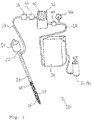
- the sole figure shows a subsurface transmittance meter 20 which is suitable for determining the colmation of sediments.
- This has an injection element 22, executed in the illustrated embodiment as a lance, which is insertable into a sediment.
- a cavity 24 is formed through which water can be passed to outlet openings 26.
- the outlet openings 26 are arranged in the region of the free end and distributed uniformly over the outer circumference of the injection element 22.
- the injection element 22 is connected in the embodiment shown with a line 28, which ultimately ends in a container 30. Within the container 30 is arranged water to be injected into the sediment.
- a pressure increasing device 32 serves to increase the pressure level at which the water is injected into the sediment.
- the pressure increasing device 32 is designed as a manual pump 34, via which the pressure level in the container 30 can be increased.
- the subsurface transmittance meter 20 further comprises a measuring device 36, via which a measurement from the group of injected water volume, period of water injection or pressure level of the water injection is feasible. Accordingly, the necessary elements, such as a volumeter 38, a pressure gauge and / or a clock are available.
- a timed valve 40 opens the inlet into the injection element 22 for a defined period of time.
- This valve 40 may be formed by a manual valve or a solenoid valve with time setting.
- a display device 42 serves to display measured values. Via the display device 42, all relevant data can be displayed, for example the measured pressure level, the injected water volume or the time of water injection. In particular, the time to be measured can also be set via the display device.
- the indicator 42 may be external or integral with the meter.
- an additional pressure indicator 44 is provided.
- the defined overpressure or the desired pressure level can be ensured by means of an adjustable pressure relief valve 46.
- the injection element 22 has a colored area 48, which indicates a desired depth of penetration into the sediment.
- This colored area can be dispensed with, but it can also be replaced by a scale, for example with a centimeter display.
- an impact weight 50 is provided.
- a relatively large external thread is conceivable that the injection element 22 can be screwed into the sediment.
Landscapes
- Life Sciences & Earth Sciences (AREA)
- Chemical & Material Sciences (AREA)
- Engineering & Computer Science (AREA)
- Physics & Mathematics (AREA)
- Analytical Chemistry (AREA)
- General Engineering & Computer Science (AREA)
- Dispersion Chemistry (AREA)
- Mining & Mineral Resources (AREA)
- Paleontology (AREA)
- Civil Engineering (AREA)
- Soil Sciences (AREA)
- Structural Engineering (AREA)
- Hydrology & Water Resources (AREA)
- Fluid Mechanics (AREA)
- General Life Sciences & Earth Sciences (AREA)
- Health & Medical Sciences (AREA)
- Biochemistry (AREA)
- General Health & Medical Sciences (AREA)
- General Physics & Mathematics (AREA)
- Immunology (AREA)
- Pathology (AREA)
- Investigation Of Foundation Soil And Reinforcement Of Foundation Soil By Compacting Or Drainage (AREA)
Description
Die Erfindung betrifft ein Untergrunddurchlässigkeitsmessgerät, welches geeignet ist zur Bestimmung der Kolmation von Sedimenten und ein Verfahren zur Bestimmung der Kolmation von Sedimenten.The invention relates to a subsurface transmittance measuring device which is suitable for determining the sedimentation of sediments and a method for determining the sedimentation of sediments.
Die Durchlässigkeit bzw. die Versickerungsfähigkeit von Untergründen wird unter anderem maßgeblich durch Kolmation beeinflusst. Kolmation bezeichnet die Verstopfung feiner Lückensystem in den Sanden, Kiesen und Schottern der Gewässersohle und die Verminderung des Wasserflusses in den Sedimenten.The permeability or infiltration capacity of substrates is significantly influenced, among other things, by colmation. Colmation refers to the clogging of fine gap systems in the sands, gravels and pebbles of the river bottom and the reduction of water flow in the sediments.
Jedes Jahr erodieren in Europa 970 Millionen Tonnen Boden. Der größte Teil dieser Feinsedimente wird in die Fließgewässer eingetragen. Auch durch Abschläge aus der Kanalisation bei Starkregenereignissen werden in Siedlungsgebieten und entlang großer versiegelter Flächen (wie z.B. Autobahnen) partikuläre Schmutzstoffe organischer und anorganischer Art in Bäche und Flüsse eingetragen. Auch dies führt zu Kolmation.Every year, 970 million tons of soil erode in Europe. Most of these fine sediments are introduced into the watercourses. Also by means of deductions from the sewage system in heavy rainfall events, particulate pollutants of organic and inorganic nature are introduced into streams and rivers in settlement areas and along large sealed surfaces (such as highways). This too leads to colmation.
Dort verstopfen sie die feinen Lückensysteme in den Sanden, Kiesen und Schottern der Gewässersohle, die sogenannte hyporheische Zone. Damit wird der Wasserfluss und -austausch zwischen Oberflächenwasser, hyporheischer Zone und Grundwasser verhindert.There they clog the fine gap systems in the sands, gravels and gravel of the riverbed, the so-called hyporheic zone. This prevents water flow and exchange between surface water, hyporheic zone and groundwater.
Kolmation ist unter anderem auch ein Problem für Bio-Kläranlagen und Versickerungsanlagen. Auch durch Wurzelwachstum können die Bodenporen verstopfen (kolmatieren). Eine weitere Form ist die Verschlämmung der Bodenkrume durch Stark- oder Dauerregen als Problemfall der Landwirtschaft.Kolmation is also a problem for bio-wastewater treatment plants and infiltration systems. Root growth can also clog the soil pores. Another form is the mud of the soil crumb by heavy or continuous rain as a problem of agriculture.
Bei der Untersuchung und Bewertung kolmatierter Fließgewässer wird die hyporheische Zone meist völlig außer Acht gelassen, was meist zu einem diffusen Ergebnis führt: Obwohl Struktur und Wasserqualität gut oder sehr gut sind, zeigt die ökologische Bewertung nur einen mittelmäßigen Zustand an ("allgemeine Degradation"). Da Kolmation bei all jenen Fließgewässern auftritt, die in landwirtschaftlich genutzten Regionen und durch Siedlungsgebiete verlaufen, dürfte der größte Teil der europäischen Bäche und Flüsse davon betroffen sein.The hyporheic zone is usually completely ignored when examining and evaluating fumigated rivers, which usually leads to a diffuse result: although structure and water quality are good or very good, the ecological assessment only indicates a mediocre state ("general degradation"). , As colmation occurs in all those running waters in agricultural and settlement areas, most of the European streams and rivers are likely to be affected.
Derzeit gibt es jedoch keine standardisierten Verfahren zur Erfassung und Bewertung der Kolmation von Fließgewässersedimenten. Soweit überhaupt berücksichtig, wird die Kolmation geschätzt. Methoden zur quantitativen Erfassung der Kolmation existieren bisher nicht.At present, however, there are no standardized methods for the detection and evaluation of the colmation of river sediments. If considered at all, the colmation is estimated. Methods for quantitative detection of colmation do not yet exist.
Es sind Messgeräte und Verfahren bekannt, über die zwar die Durchlässigkeit von Untergründen bestimmbar ist, diese eignen sich jedoch nicht zur Bestimmung der Kolmation. Beispielsweise beschreibt die
Die bisher üblichen Ansätze zur Erfassung der inneren Kolmation lassen sich in qualitative Verfahren, messtechnische Verfahren und Berechnungsverfahren unterteilen. Zu den qualitativen Verfahren gehören beispielsweise die visuelle Beurteilung, die sogenannte Stiefelprobe und die optische Bewertung an trockenen Teilen der Sohle. Alle diese qualitativen Verfahren haben den Nachteil, dass sie sehr subjektiv sind und insofern einen objektiven Vergleich verschiedener Beurteilungen nicht zulassen.The hitherto customary approaches for detecting the internal colmation can be subdivided into qualitative methods, metrological methods and calculation methods. The qualitative methods include, for example, the visual assessment, the so-called boot test and the optical evaluation of dry parts of the sole. All these qualitative methods have the disadvantage that they are very subjective and thus do not allow an objective comparison of different judgments.
Die messtechnischen Verfahren beinhalten Sedimentfallen, Siebanalysen, Grundwasserstandsmessungen und Abflussmessungen. Sedimentfallen lassen nur eine qualitative Beurteilung zu, die wiederum abhängig ist vom Versuchsaufbau. Siebanalysen sind aufwendig und eine abgestufte Beurteilung der Kolmation ist kaum möglich. Die Beurteilung des Grundwasserstands lässt ebenfalls keine differenzierte Bewertung der Kolmation zu, während bei Abflussmessungen die Bewertung der Kolmation nicht eindeutig ist.The metrological methods include sediment traps, sieve analyzes, groundwater level measurements and runoff measurements. Sediment traps allow only a qualitative assessment, which in turn depends on the experimental set-up. Sieve analyzes are complex and a graduated assessment of the colmation is hardly possible. The assessment of the groundwater level also does not allow for a differentiated assessment of the colmation, whereas for discharge measurements the assessment of the colmation is not clear.
Berechnungsverfahren basieren auf der Durchlässigkeit in Funktion der Zeit. Der Aufwand ist sehr groß und die Messung vieler Eingabeparameter ist erforderlich.Calculation methods are based on the permeability as a function of time. The effort is very large and the measurement of many input parameters is required.
Eine Methodik zur Erhebung der inneren Kolmation unter Wasser beinhaltet das Einbringen eines rund 33 cm langen Stahlstiftes in den Boden bzw. die Kiessohle. Der Stahlstift reicht dabei 16,5 cm in den Boden hinein. Eine Schnur wird mit einer Schlaufe um den Stift gelegt. Am anderen Ende der Schnur ist eine Federwaage befestigt. Mit zunehmender Kraft wird rechtwinklig zum Stift gezogen, bis sich der Stift aus dem Kies löst. Die Kraft die dazu notwendig ist, kann auf der Federwaage abgelesen werden. Nachteilig bei diesem Verfahren ist u.a., dass der Widerstand von nicht sichtbaren Gegebenheiten im Boden abhängig ist. Auch hat sich gezeigt, dass zahlreiche Messungen notwendig sind, um ein relativ objektives Ergebnis zu erreichen.A methodology for collecting the inner colmation under water involves the introduction of a 33 cm long steel pin into the ground or the Kiessohle. The steel pin reaches 16.5 cm into the ground. A string is placed around the pencil with a loop. At the other end of the string a spring balance is attached. With increasing force is drawn at right angles to the pin, until the pin is released from the gravel. The force that is necessary for this can be read on the spring balance. A disadvantage of this method is, inter alia, that the resistance of non-visible conditions in the ground is dependent. It has also been shown that numerous measurements are necessary to achieve a relatively objective result.
Die Versickerungsfähigkeit des Untergrundes ist auch bei Baugrunderkundungen oder bei Durchlässigkeitsmessungen in Grundwasserleitern sowie Böden von Bedeutung. Über die oben genannten Verfahren hinaus sind auch für diese Anwendungsbereiche in terrestrischen Böden keine Messgeräte oder keine einfach anwendbaren Verfahren bekannt. Beispielsweise ist es bei der Herstellung von Versickerungsmulden, Rigolen oder Retentionsbodenfilterbecken notwendig, die Versickerungsfähigkeit des Bodens bzw. des Untergrundes im Vorfeld sicher zu bestimmen. Nur wenn Regenwasser in ausreichender Geschwindigkeit versickern kann, ist eine solche technische Versickerungsanlage genehmigungsfähig.The infiltration capacity of the subsoil is also of importance in subsoil investigations or in permeability measurements in aquifers and soils. In addition to the above-mentioned methods, no measuring devices or simply applicable methods are known for these applications in terrestrial soils either. For example, in the production of infiltration troughs, trenches or retention bottom filter basins, it is necessary to reliably determine the infiltration capacity of the soil or of the subsoil in advance. Only if rainwater can seep in sufficient speed, such a technical infiltration system is approved.
Die Aufgabe der vorliegenden Erfindung besteht darin, ein Untergrunddurchlässigkeitsmessgerät zu schaffen, mit dem der Grad der inneren Kolmation zuverlässig und wiederholbar gemessen werden kann. Weiterhin sollen beispielsweise auch die Untersuchung von Baugrund hinsichtlich der Versickerungsfähigkeit des Untergrunds oder auch Durchlässigkeitsmessungen in Grundwasserleitern und Böden möglich sein. Das Untergrunddurchlässigkeitsmessgerät soll dabei robust und einfach aufgebaut, mögliche Fehlerquellen sollen minimiert sein. Die Herstellung des Untergrunddurchlässigkeitsmessgerätes soll darüber hinaus kostengünstig und die Wartung und Instandhaltung mit geringem Aufwand durchführbar sein. Weiterhin ist es Aufgabe der vorliegenden Erfindung, ein Verfahren zur Messung der inneren Kolmation vorzuschlagen, welches insbesondere mit dem erfindungsgemäßen Untergrunddurchlässigkeitsmessgerät durchführbar ist.The object of the present invention is to provide a subsurface transmittance meter with which the degree of internal colmation can be reliably and repeatedly measured. Furthermore, for example, the investigation of soil with regard to the infiltration capability of the subsurface or permeability measurements in aquifers and soils should be possible. The underground permeability meter is designed to be robust and simple, possible sources of error should be minimized. In addition, the production of the underground permeability meter should be cost-effective and maintenance and servicing should be feasible with little effort. It is another object of the present invention to provide a method for measuring the internal Kolmation, which can be carried out in particular with the underground permeability measuring device according to the invention.
Erfindungsgemäß wird die Aufgabe durch ein Untergrunddurchlässigkeitsmessgerät gelöst, gemäß Anspruch 1. Weiterhin wird die Aufgabe durch ein Verfahren zur Bestimmung der Kolmation von Sedimenten gelöst, gemäß Anspruch 11. Der Begriff Untergrund umfasst im Sinne der Erfindung sämtliche Untergründe, insbesondere Lockersedimente (Bachsedimente), Böden, Geschiebe und sonstige geologischen Untergründe.According to the invention, the object is achieved by a subsurface transmittance meter, according to claim 1. Furthermore, the object is achieved by a method for determining the colmation of sediments, according to claim 11. The term subsurface in the context of the invention comprises all substrates, in particular loose sediments (soils), soils , Debris and other geological undergrounds.
Die Erfinder haben erkannt, dass ein belastbares Verfahren zur quantitativen Messung der Kolmation die Durchlässigkeit der Sedimente für Wasser ermitteln können muss. Das Ergebnis muss zu einer Art Parameter führen, der mit dem Durchlässigkeitsbeiwert für Grundwasserleiter (Kf-Wert) vergleichbar ist.The inventors have recognized that a robust method of quantitative measurement of colmation must be able to determine the permeability of the sediments to water. The result must lead to a kind of parameter that is comparable to the permeability coefficient for aquifers (Kf value).
Erfindungsgemäß erfolgt die Messung der Durchlässigkeit von Sedimenten durch die gezielte Intrusion bzw. Injektion von Wasser, mittels eines Injektionselementes in das zu untersuchende Sediment.According to the invention, the permeability of sediments is measured by the targeted intrusion or injection of water, by means of an injection element in the sediment to be examined.
Der Begriff Überdruck bezeichnet im Sinne der Erfindung den Zustand an der oder den Austrittsöffnungen. Ein gewisser Überdruck ist vorgesehen, um das Wasser von innen nach außen durch die Austrittsöffnungen zu leiten. Die Höhe des Druckniveaus ist insbesondere vom Sediment, aber auch von der gewünschten Zeitdauer der Injektion abhängig. Erfolgt das Einleiten über einen langen Zeitraum, kann ein minimaler Überdruck ausreichen. Bei bestimmten Sedimenten kann es sogar möglich sein, das Wasser ohne Überdruck, also mit Umgebungsdruck einzuleiten.The term overpressure referred to in the context of the invention, the state at the or the outlet openings. A certain overpressure is provided to direct the water from the inside to the outside through the outlet openings. The level of the pressure level depends in particular on the sediment, but also on the desired duration of the injection. If the initiation is over a long period of time, a minimum overpressure may suffice. With certain sediments it may even be possible to introduce the water without overpressure, ie with ambient pressure.
Das Injektionselement ist vorzugsweise durch eine Lanze aus einem widerstandsfähigen, möglichst starren Material gebildet. Dies ist insbesondere deshalb sinnvoll, weil die Lanze in das zu untersuchende Sediment eingebracht werden muss. Je nach Zusammensetzung des Sediments kann das Injektionselement eingedrückt, eingeschlagen oder eingedreht bzw. gebohrt werden. Entsprechend kann die Lanze weitere Elemente aufweisen, die ein Einbringen in den Boden erleichtern. Hierzu zählt bei hilfsweise ein Schlaggewicht, welches fest an der Lanze befestigt ist, oder eine besonders widerstandsfähige Spitze am freien Ende. Denkbar ist auch relativ grobes Außengewinde, das das Eindrehen bzw. Einschrauben in den Untergrund ermöglicht.The injection element is preferably formed by a lance of a resistant, rigid material as possible. This is particularly useful because the lance must be introduced into the sediment to be examined. Depending on the composition of the sediment, the injection element can be pressed, hammered or screwed or drilled. Accordingly, the lance may have other elements that facilitate insertion into the ground. This includes, in the alternative, an impact weight, which is firmly attached to the lance, or a particularly resistant tip at the free end. It is also conceivable relatively coarse external thread that allows screwing or screwing into the ground.
Alternativ kann das Injektionselement beispielsweise auch durch einen Schlauch gebildet sein, der auf bzw. in ein Flussbett gelegt wird und dort solange verbleibt, bis er sich aufgrund von Sedimentation im Untergrund befindet.Alternatively, the injection element may for example also be formed by a hose which is placed on or in a river bed and remains there until it is due to sedimentation in the ground.
Unabhängig von der Ausbildung des Injektionselementes beispielsweise als Lanze oder Schlauch kann das Injektionselement erfindungsgemäß auch in den Untergrund eingegraben werden.Regardless of the design of the injection element, for example, as a lance or hose, the injection element according to the invention can also be buried in the ground.
In ihrem Innern weist das Injektionselement einen wasserleitenden Hohlraum auf, wobei am freien Ende des Injektionselements mehrere über den Außenumfang des Injektionselements verteilte Austrittsöffnungen vorgesehen sind. Durch den Hohlraum wird das Wasser zu den Austrittsöffnungen geleitet und in das umgebende Sediment injiziert.In its interior, the injection element has a water-conducting cavity, wherein a plurality of outlet openings distributed over the outer circumference of the injection element are provided at the free end of the injection element. Through the cavity, the water is directed to the outlet openings and injected into the surrounding sediment.
Eine Druckerhöhungsvorrichtung bewirkt dabei eine Erhöhung des Druckniveaus des zu injizierenden Wassers. Die Druckerhöhungsvorrichtung kann dabei durch eine einfache manuell angetriebene Pumpe gebildet sein, denkbar ist aber auch eine elektrisch oder motorisch angetriebene Pumpe.A pressure increasing device causes an increase in the pressure level of the water to be injected. The pressure increasing device may be formed by a simple manually driven pump, but also conceivable is an electrically or motor-driven pump.
Das zu injizierende Wasser kann entweder aus der Umwelt, beispielsweise aus einem Gewässer entnommen werden, erfindungsgemäß kann aber auch ein Behälter vorgesehen sein, in dem Wasser bevorratet ist. Letzteres hat den Vorteil, dass das zu injizierende Wasser bestimmten definierten Anforderungen entsprechen kann. Bei Verwendung eines Behälters kann dieser beispielsweise mit einer Pumpe in Verbindung stehen, über die das Druckniveau innerhalb des Behälters auf das gewünschte Niveau erhöht werden kann. Über ein Ventil, vorzugsweise ein Hand- oder Magnetventil wird die Flüssigkeit über eine Auslassleitung aus dem unter Druck stehenden Behälter in das Injektionselement gefördert. Alternativ kann innerhalb des Behälters eine Tauchpumpe oder auch eine Kreiselpumpe in der Auslassleitung vorgesehen sein.The water to be injected can either be taken from the environment, for example from a body of water, but according to the invention a container can also be provided in which water is stored. The latter has the advantage that the water to be injected can meet certain defined requirements. When using a container, this can for example be in communication with a pump, via which the pressure level can be increased within the container to the desired level. Via a valve, preferably a manual or solenoid valve, the liquid is conveyed via an outlet line from the pressurized container into the injection element. Alternatively, a submersible pump or a centrifugal pump can be provided in the outlet line within the container.
Vorteilhafterweise ist der Behälter mit Gurten versehen, die es erlauben, diesen beispielsweise auf dem Rücken zu tragen.Advantageously, the container is provided with straps which allow it to be worn, for example, on the back.
Die mehrerer, über die Außenfläche des Injektionselements verteilten Auslassöffnungen haben einen genormten Durchmesser. Grundsätzlich ist der Durchmesser in Abhängigkeit des zu untersuchenden Sediments zu wählen, Größenordnungen von 1 mm bis 5 mm, vorzugsweise 1 mm bis 2 mm haben sich als sinnvoll erwiesen. Je nach Sediment können aber Durchmesser von weniger als 1 mm zielführend sein.The plurality of outlet openings distributed over the outer surface of the injection element have a standardized diameter. Basically, the diameter should be selected depending on the sediment to be examined, orders of magnitude of 1 mm to 5 mm, preferably 1 mm to 2 mm have proven to be useful. Depending on the sediment but diameter of less than 1 mm can be effective.
Um eine definierte Zeitdauer der Wasserinjektion zu gewährleisten, kann erfindungsgemäß ein zeitgesteuertes Ventil vorgesehen sein. Alternativ kann die Zeitdauer der Wasserinjektion über eine externe Stoppuhr gemessen werden.In order to ensure a defined period of water injection, a time-controlled valve can be provided according to the invention. Alternatively, the duration of the water injection can be measured via an external stopwatch.
Bei der erfindungsgemäßen Messung bzw. dem erfindungsgemäßen Verfahren sind vorzugsweise drei Parameter zu berücksichtigen:
- 1.) der erforderliche Einspritzdruck
- 2.) die Zeit, in der
- 3.) eine bestimmte Wassermenge in das Sediment injiziert wird
- 1.) the required injection pressure
- 2.) the time in which
- 3.) a certain amount of water is injected into the sediment
Zwei dieser drei Parameter werden konstant gehalten, der dritte gemessen. Dieser entspricht dann der jeweiligen Durchlässigkeit der Sedimente. Über die Eichung mit Sedimenten definierter Durchlässigkeit wird der Abgleich mit eingeführten Messgrößen zur Sedimentcharakterisierung, z.B. Kf-Wert in m/s, möglich. Dabei kann es sinnvoll sein, wenn es sich bei dem Injektionselement um eine Lanze handelt, die Eindringtiefe der Lanze stets gleich ist. Aus diesem Grund weist die Lanze vorteilhafterweise eine Skalierung oder Farbindikatoren auf ihrer Außenseite auf. Beispielsweise kann der Bereich des freien Endes, ausgehend von der Spitze der Lanze gut sichtbar gefärbt sein. Beim Einschlagen muss dann lediglich darauf geachtet werden, dass der gefärbte Bereich in das Erdreich eindringt. Da die Lanze auch unter Wasser verwendbar sein soll, sollte die Farbgebung so gewählt werden, dass sie auch durch Wasser hindurch gut erkennbar ist. Alternativ oder zusätzlich kann auch ein Muster verwendet werden, wenn dies die Sichtbarkeit erhöht.Two of these three parameters are kept constant, the third measured. This then corresponds to the respective permeability of the sediments. Calibration with sediment-defined permeability is compared with established parameters for sediment characterization, e.g. Kf value in m / s, possible. It may be useful if it is the injection element is a lance, the penetration depth of the lance is always the same. For this reason, the lance advantageously has a scale or color indicators on its outside. For example, the area of the free end may be clearly visible from the tip of the lance. When hammering then only has to be taken to ensure that the colored area penetrates into the soil. Since the lance should also be usable under water, the color should be chosen so that it is well visible even through water. Alternatively or additionally, a pattern can also be used if this increases the visibility.
Soll der Einfluss auf das umgebende Material des Sediments möglichst gering gehalten werden, ist erfindungsgemäß vorgesehen, das Injektionselement möglichst langsam in den Untergrund einzubringen. Beispielsweise kann es mit einem Gewicht oder mit Federkraft beaufschlagt und zum Beispiel mithilfe eines Dreibeins langsam in den Untergrund gedrückt werden.If the influence on the surrounding material of the sediment is to be kept as low as possible, it is provided according to the invention to introduce the injection element as slowly as possible into the substrate. For example, it can be loaded with a weight or with spring force and, for example, slowly pushed into the ground using a tripod.
Bei der Messung werden Einspritzdruck (p) und Zeit (t) vorteilhafterweise konstant gehalten und die injizierte Wassermenge (V) gemessen. In einer Versuchsanordnung hat sich folgende Vorgehensweise mit den genannten Werten als sinnvoll erwiesen:
- 1.) in einem Wassergefäß wird ein Druck von 1 bar eingestellt und
- 2.) über einen Zeitraum von 5 Sekunden
- 3.) Wasser in das Sediment injiziert und diese Wassermenge elektronisch gemessen.
- 1.) in a water vessel, a pressure of 1 bar is set and
- 2.) over a period of 5 seconds
- 3.) injected water into the sediment and measured this amount of water electronically.
Daraus ergibt sich bei p = 1 bar die Fließrate (Q = ml/5s bzw. m3/s), die die Durchlässigkeit widergibt.At p = 1 bar, this results in the flow rate (Q = ml / 5s or m 3 / s), which reflects the permeability.
Der Druck, mit dem das Wasser in das Sediment eingebracht wird, kann je nach Anwendungsfall auch deutlich höher oder deutlich geringer sein. Beispielsweise können Messungen zu sinnvollen und belastbaren Ergebnissen führen, bei denen der Druck deutlich weniger als 1 bar beträgt. Messungen mit geringerem Druck führen auch zu geringerem Einfluss auf den das Injektionselement umgebende Sediment.The pressure with which the water is introduced into the sediment, depending on the application, can also be significantly higher or significantly lower. For example, measurements can lead to meaningful and resilient results in which the pressure is significantly less than 1 bar. Measurements with lower pressure also lead to less influence on the sediment surrounding the injection element.
Je größer das eingebrachte Wasservolumen, d. h. die Fließrate, desto durchlässiger ist das Sediment und umso geringer die Kolmation. Der Arbeitsdruck und die Injektionszeit lassen sich bei Bedarf anpassen.The larger the volume of water introduced, d. H. the flow rate, the more permeable the sediment and the lower the colmation. The working pressure and the injection time can be adjusted as needed.
Grundsätzlich ist auch die Messung eines anderen Parameters als der Fließrate möglich. Dazu könnte z.B. das injizierte Wasservolumen und ein weiterer Parameter (Einspritzdruck oder Zeit) konstant gehalten und entweder die Zeit oder der Druckverlust gemessen werden.In principle, it is also possible to measure a parameter other than the flow rate. This could be e.g. the injected water volume and another parameter (injection pressure or time) are kept constant and either the time or the pressure loss are measured.
Zusammen mit dem Injektionselement können zusätzliche Sensoren in das Sediment eingebracht werden, z.B. zur Messung der Temperatur, der Leitfähigkeit, der Lokalisation der Messstelle (GPS) oder weiterer Parameter.Together with the injection element, additional sensors may be introduced into the sediment, e.g. for measuring the temperature, the conductivity, the localization of the measuring point (GPS) or other parameters.
Die im oben beschriebenen Verfahren dargestellten mechanischen Kompartimente lassen sich durch elektronische Bauteile ergänzen bzw. substituieren. Eine digitale Erfassung und automatisierte Weiterverarbeitung ist möglich.The mechanical compartments illustrated in the method described above can be supplemented or substituted by electronic components. Digital recording and automated further processing is possible.
Das oben beschriebene Verfahren ist grundsätzlich auch für den Einsatz im marinen Milieu geeignet (z.B. Hafenbecken und Off Shore). Außerdem lassen sich Messungen in Stillgewässern, wie Seen, Weihern und Teichen durchführen.The method described above is also generally suitable for use in the marine environment (for example, harbor basin and off shore). In addition, measurements can be made in still waters such as lakes, ponds and ponds.
Durch stationären Dauerbetrieb von Injektionselementen in Gewässern lassen sich Langzeitstudien der Kolmation anstellen. Ein Einsatz von Datenloggern mit automatischer Übermittlung der Messergebnisse an ein digitales System ist möglich.Stationary continuous operation of injection elements in bodies of water allows long-term studies of the colmation. A use of data loggers with automatic transmission of the measurement results to a digital system is possible.
In einer besonders vorteilhaften Ausführungsvariante sind sämtliche Elemente, die elektrische Energie benötigen derart ausgelegt, dass sie über 9V oder 12 V oder 24 V betrieben werden können. Dies minimiert die Größe von Batterien oder Akkus und ermöglicht insbesondere auch eine Energieversorgung über Solarelemente, was bei langen Feldmessungen in der Natur besonders hilfreich ist.In a particularly advantageous embodiment, all elements that require electrical energy are designed so that they can be operated via 9V or 12V or 24V. This minimizes the size of batteries or rechargeable batteries and in particular also allows energy supply via solar elements, which is particularly helpful in long field measurements in nature.
Die Erfindung wird anhand der nachfolgenden Figur näher erläutert. Diese dabei nur beispielhaft zu verstehen, insbesondere sind die Größenverhältnisse nicht maßstabsgetreu. Die Figur stellt nur ein Ausführungsbeispiel der Erfindung dar.The invention will be explained in more detail with reference to the following figure. These only by way of example, in particular, the size ratios are not to scale. The figure represents only one embodiment of the invention.
Die einzige Figur zeigt ein Untergrunddurchlässigkeitsmessgerät 20, welches zur Bestimmung der Kolmation von Sedimenten geeignet ist. Dieses weist ein Injektionselement 22, im gezeigten Ausführungsbeispiel ausgeführt als Lanze, auf, welche in ein Sediment einführbar ist.The sole figure shows a
Im Inneren des Injektionselements 22 ist ein Hohlraum 24 ausgebildet, durch den Wasser zu Austrittsöffnungen 26 geleitet werden kann. Die Austrittsöffnungen 26 sind im Bereich des freien Endes angeordnet und gleichmäßig über den Außenumfang des Injektionselementes 22 verteilt.In the interior of the
Das Injektionselement 22 ist im gezeigten Ausführungsbeispiel mit einer Leitung 28 verbunden, die letztendlich in einem Behälter 30 endet. Innerhalb des Behälters 30 ist Wasser angeordnet, das in das Sediment injiziert werden soll.The
Eine Druckerhöhungsvorrichtung 32 dient der Erhöhung des Druckniveaus mit dem das Wasser in das Sediment injiziert wird. Im gezeigten Ausführungsbeispiel ist die Druckerhöhungsvorrichtung 32 als manuelle Pumpe 34 ausgeführt, über die das Druckniveau im Behälter 30 erhöht werden kann.A pressure increasing device 32 serves to increase the pressure level at which the water is injected into the sediment. In the embodiment shown, the pressure increasing device 32 is designed as a manual pump 34, via which the pressure level in the
Das Untergrunddurchlässigkeitsmessgerät 20 weist weiterhin ein Messgerät 36 auf, über das eine Messung aus der Gruppe injiziertes Wasservolumen, Zeitraum der Wasserinjektion oder Druckniveau der Wasserinjektion durchführbar ist. Entsprechend sind die dafür notwendigen Elemente, wie beispielsweise ein Volumenmessgerät 38, ein Druckmessgerät und/oder eine Uhr vorhanden.The
Ein zeitgesteuertes Ventil 40 öffnet den Zulauf in das Injektionselement 22 für eine definierte Zeitdauer. Dieses Ventil 40 kann durch ein Handventil oder auch ein Magnetventil mit Zeiteinstellung gebildet sein.A timed
Ein Anzeigegerät 42 dient der Anzeige gemessener Werte. Über das das Anzeigegerät 42 können alle relevanten Daten angezeigt werden, zum Beispiel das gemessene Druckniveau, das injizierte Wasservolumen oder der Zeitraum der Wasserinjektion. Insbesondere kann über das Anzeigegerät auch die zu messende Zeitdauer eingestellt werden.A
Das Anzeigegerät 42 kann extern oder als integraler Bestandteil des Messgerätes ausgeführt sein.The
Im gezeigten Ausführungsbeispiel ist eine zusätzliche Druckanzeige 44 vorgesehen.In the embodiment shown, an
Der definierte Überdruck bzw. das gewünschte Druckniveau kann mit Hilfe eines einstellbaren Überdruckventils 46 gewährleistet werden.The defined overpressure or the desired pressure level can be ensured by means of an adjustable
Erkennbar ist, dass das Injektionselement 22 einen farbigen Bereich 48 aufweist, der eine gewünschte Eindringtiefe in das Sediment anzeigt. Auf diesen farbigen Bereich kann verzichtet werden, er kann aber auch durch eine Skalierung, beispielsweise mit Zentimeteranzeige, ersetzt werden.It can be seen that the
Um ein Einbringen des Injektionselements 22 in das Sediment zu erleichtern, ist ein Schlaggewicht 50 vorgesehen. Alternativ ist auch ein relativ großes Außengewinde denkbar, über dass das Injektionselement 22 in das Sediment einschraubbar ist.In order to facilitate introduction of the
Mithilfe des erfindungsgemäßen Untergrunddurchlässigkeitsmessgerätes und des erfindungsgemäßen Verfahrens ist es erstmals möglich, die Kolmation von Fließgewässersedimenten zu erfassen.With the aid of the underground permeability measuring device according to the invention and the method according to the invention, it is possible for the first time to detect the colmation of flowing water sediments.
Claims (13)
- A substrate permeability measuring device (20) suitable for determining the colmation of sediments, comprising- an injection element (22) for insertion into a sediment to be examined, comprising:- several outlet openings (26) uniformly distributed over the outer circumference of the injection element (22), the outlet openings (26) being disposed in the region of the free end of the injection element (22) and having a diameter in the range of 1 - 5 mm, and- a cavity (24) for conducting water to the outlet openings (26),- a pressure increasing device (32) via which the water can be injected with overpressure through the injection element (22) and the outlet opening (26) into the sediment surrounding the injection element (22).
- The substrate permeability measuring device (20) according to claim 1, characterized in that the pressure increasing device (32) is configured in such a way that at least a defined pressure level can be generated.
- The substrate permeability measuring device (20) according to claim 1 or claim 2, characterized in that at least one measuring device (36) for at least one measurement from the group injected water volume, period of time of the injection of water, or pressure level of the injection of water is provided.
- The substrate permeability measuring device (20) according to claim 3, characterized in that a display device (42) for displaying the measured values is provided.
- The substrate permeability measuring device (20) according to any one of the claims 1 to 4, characterized in that a container (30) for the water to be injected, which is in fluid communication with the injection element (22), is provided.
- The substrate permeability measuring device (20) according to any one of the claims 3 to 5, characterized in that a time-controlled valve (40) is provided, by means of which the period of time of the injection of water can be adjusted.
- The substrate permeability measuring device (20) according to any one of the claims 1 to 6, characterized in that the pressure increasing device (32) is formed by a pump (34) that can be operated manually.
- The substrate permeability measuring device (20) according to any one of the claims 1 to 7, characterized in that the pressure increasing device (32) is formed by an electrically operated pump.
- The substrate permeability measuring device (20) according to any one of the claims 1 to 8, characterized in that the injection element (22) is configured as a lance.
- The substrate permeability measuring device (20) according to any one of the claims 1 to 8, characterized in that the injection element (22) is configured as a hose.
- A method for determining the colmation of sediments, characterized by the method steps- inserting, into a sediment to be examined, an injection element (22) with a cavity (24) for conducting water to several outlet openings (26), which are uniformly distributed over the outer circumference and are disposed in the region of the free end of the injection element (22) and have a diameter in the range of 1 - 5 mm,- injecting water with overpressure through the injection element (22) and the outlet opening (26) into the sediment, while setting and maintaining two parameters from the groupd) injected water volume,e) period of time of the injection of water, orf) pressure level of the injection of water,- determining the parameter a), b) or c) that was not set or maintained.
- The method according to claim 11, characterized by a comparison of the determined parameter with reference values of that parameter that were previously determined for sediments with a defined permeability.
- The method according to claim 11 or claim 12, characterized in that the pressure level of the injection of water is less than 1 bar.
Priority Applications (4)
| Application Number | Priority Date | Filing Date | Title |
|---|---|---|---|
| EP15190408.3A EP3159671B1 (en) | 2015-10-19 | 2015-10-19 | Base permeability measuring device |
| PCT/EP2016/074917 WO2017067898A1 (en) | 2015-10-19 | 2016-10-18 | Substrate permeability measuring device |
| EP16785113.8A EP3365656A1 (en) | 2015-10-19 | 2016-10-18 | Substrate permeability measuring device |
| US15/769,656 US20180252629A1 (en) | 2015-10-19 | 2016-10-18 | Substrate permeability measuring device |
Applications Claiming Priority (1)
| Application Number | Priority Date | Filing Date | Title |
|---|---|---|---|
| EP15190408.3A EP3159671B1 (en) | 2015-10-19 | 2015-10-19 | Base permeability measuring device |
Publications (2)
| Publication Number | Publication Date |
|---|---|
| EP3159671A1 EP3159671A1 (en) | 2017-04-26 |
| EP3159671B1 true EP3159671B1 (en) | 2018-07-11 |
Family
ID=54337158
Family Applications (1)
| Application Number | Title | Priority Date | Filing Date |
|---|---|---|---|
| EP15190408.3A Active EP3159671B1 (en) | 2015-10-19 | 2015-10-19 | Base permeability measuring device |
Country Status (1)
| Country | Link |
|---|---|
| EP (1) | EP3159671B1 (en) |
Families Citing this family (1)
| Publication number | Priority date | Publication date | Assignee | Title |
|---|---|---|---|---|
| CN109252555B (en) * | 2018-10-31 | 2021-01-19 | 中国一冶集团有限公司 | Device for measuring thickness of pile foundation sediment through rotary drilling coring and construction method |
Family Cites Families (4)
| Publication number | Priority date | Publication date | Assignee | Title |
|---|---|---|---|---|
| US2376878A (en) * | 1941-12-15 | 1945-05-29 | Dow Chemical Co | Method of determining the permeability of earth formations |
| FR2576415B1 (en) * | 1985-01-18 | 1987-02-27 | Rech Geolog Miniere | APPARATUS FOR MEASURING THE PERMEABILITY OF TERRAIN AND ESPECIALLY OF VERY WEAKLY PERMEABLE FORMATIONS, OF THE PULSE TEST TYPE |
| DE4319976A1 (en) * | 1993-06-11 | 1995-02-02 | Blz Geotechnik Gmbh | Method and arrangement for determining the permeability of a ground (soil) formation |
| US5548991A (en) * | 1995-03-09 | 1996-08-27 | Ritson; Marc J. | Permeameter probe |
-
2015
- 2015-10-19 EP EP15190408.3A patent/EP3159671B1/en active Active
Non-Patent Citations (1)
| Title |
|---|
| None * |
Also Published As
| Publication number | Publication date |
|---|---|
| EP3159671A1 (en) | 2017-04-26 |
Similar Documents
| Publication | Publication Date | Title |
|---|---|---|
| Evans et al. | Effects of agricultural water table management on drainage water quality | |
| DE102013201982A1 (en) | Reservoir of an agricultural distribution machine with capacitive filling level measuring device | |
| EP3159671B1 (en) | Base permeability measuring device | |
| Wesström et al. | The effects of controlled drainage on subsurface outflow from level agricultural fields | |
| DE102017004167B4 (en) | Method and device for taking liquid samples from any depth, in particular for sampling from groundwater wells English: v3.espacenet.com/textdoc? | |
| DE69704790T2 (en) | STAINLESS STEEL AUSTENITIC STEEL AND THEIR USE | |
| WO2017067898A1 (en) | Substrate permeability measuring device | |
| DE202015105525U1 (en) | Underground Transmission Rate Tester | |
| DE19933391B4 (en) | Geschiebückhalteschacht with measuring arrangement | |
| DE202022107159U1 (en) | Apparatus for detecting combined parameter controlled initiation conditions of a mud flow caused by heavy rainfall | |
| DE10058416C1 (en) | Determination of oxygen content of interstitial water in formations containing sediment and clay comprises feeding protective tube into formation, feeding sensor into tube and sucking water through inlet in protective tube over sensor | |
| EP1162316A1 (en) | Device to protect from wind erosion by sprinkling | |
| DE2610654A1 (en) | Rubbish tip internal settlement measurement - uses hose embedded in tip allowing position measurement by water pressure test | |
| DE4443536A1 (en) | Measuring friction characteristics of liquid, liquid-solid suspension, or fluid sludge-silt in waterway | |
| DE102011002303A1 (en) | Tree grate with gutter and cleaning device for irrigation and infiltration | |
| DE29518645U1 (en) | Device for deeply horizontal groundwater sampling | |
| EP1942344B1 (en) | Method for inspecting the behaviour of a material in a construction material | |
| DD264987A1 (en) | DEVICE FOR IN-SITU DETERMINATION OF THE INFILTRATION RATE | |
| Richards | Piping potential of unfiltered soils in existing levees and dams | |
| DE2247848C3 (en) | Rain gauge | |
| DE8435472U1 (en) | Device for subsoil irrigation in the root area of plants, especially trees | |
| DE2228224A1 (en) | FLUID PRESSURE DEPTH AND HEIGHT MEASUREMENT DEVICE | |
| DE10106906C2 (en) | Base plate for a lysimeter container | |
| Bennett et al. | Changes in run-off and groundwater conditions under saltbush grazing systems: Results of a ten year paired catchment study | |
| Scully et al. | An evaluation of earth-banked tanks for slurry storage. |
Legal Events
| Date | Code | Title | Description |
|---|---|---|---|
| PUAI | Public reference made under article 153(3) epc to a published international application that has entered the european phase |
Free format text: ORIGINAL CODE: 0009012 |
|
| AK | Designated contracting states |
Kind code of ref document: A1 Designated state(s): AL AT BE BG CH CY CZ DE DK EE ES FI FR GB GR HR HU IE IS IT LI LT LU LV MC MK MT NL NO PL PT RO RS SE SI SK SM TR |
|
| AX | Request for extension of the european patent |
Extension state: BA ME |
|
| 17P | Request for examination filed |
Effective date: 20170712 |
|
| RBV | Designated contracting states (corrected) |
Designated state(s): AL AT BE BG CH CY CZ DE DK EE ES FI FR GB GR HR HU IE IS IT LI LT LU LV MC MK MT NL NO PL PT RO RS SE SI SK SM TR |
|
| 17Q | First examination report despatched |
Effective date: 20170921 |
|
| GRAP | Despatch of communication of intention to grant a patent |
Free format text: ORIGINAL CODE: EPIDOSNIGR1 |
|
| RIC1 | Information provided on ipc code assigned before grant |
Ipc: G01N 33/24 20060101ALI20180205BHEP Ipc: G01N 15/08 20060101AFI20180205BHEP Ipc: G01N 7/00 20060101ALN20180205BHEP Ipc: E02D 1/02 20060101ALN20180205BHEP |
|
| INTG | Intention to grant announced |
Effective date: 20180227 |
|
| RAP1 | Party data changed (applicant data changed or rights of an application transferred) |
Owner name: HZ-DR. HANS JUERGEN HAHN UND DR. THOMAS ZUMBROICH |
|
| GRAS | Grant fee paid |
Free format text: ORIGINAL CODE: EPIDOSNIGR3 |
|
| GRAA | (expected) grant |
Free format text: ORIGINAL CODE: 0009210 |
|
| AK | Designated contracting states |
Kind code of ref document: B1 Designated state(s): AL AT BE BG CH CY CZ DE DK EE ES FI FR GB GR HR HU IE IS IT LI LT LU LV MC MK MT NL NO PL PT RO RS SE SI SK SM TR |
|
| REG | Reference to a national code |
Ref country code: GB Ref legal event code: FG4D Free format text: NOT ENGLISH |
|
| REG | Reference to a national code |
Ref country code: CH Ref legal event code: EP |
|
| REG | Reference to a national code |
Ref country code: AT Ref legal event code: REF Ref document number: 1017394 Country of ref document: AT Kind code of ref document: T Effective date: 20180715 |
|
| REG | Reference to a national code |
Ref country code: IE Ref legal event code: FG4D Free format text: LANGUAGE OF EP DOCUMENT: GERMAN |
|
| REG | Reference to a national code |
Ref country code: DE Ref legal event code: R096 Ref document number: 502015005002 Country of ref document: DE |
|
| REG | Reference to a national code |
Ref country code: NL Ref legal event code: MP Effective date: 20180711 |
|
| REG | Reference to a national code |
Ref country code: LT Ref legal event code: MG4D |
|
| PG25 | Lapsed in a contracting state [announced via postgrant information from national office to epo] |
Ref country code: NL Free format text: LAPSE BECAUSE OF FAILURE TO SUBMIT A TRANSLATION OF THE DESCRIPTION OR TO PAY THE FEE WITHIN THE PRESCRIBED TIME-LIMIT Effective date: 20180711 |
|
| PG25 | Lapsed in a contracting state [announced via postgrant information from national office to epo] |
Ref country code: FI Free format text: LAPSE BECAUSE OF FAILURE TO SUBMIT A TRANSLATION OF THE DESCRIPTION OR TO PAY THE FEE WITHIN THE PRESCRIBED TIME-LIMIT Effective date: 20180711 Ref country code: LT Free format text: LAPSE BECAUSE OF FAILURE TO SUBMIT A TRANSLATION OF THE DESCRIPTION OR TO PAY THE FEE WITHIN THE PRESCRIBED TIME-LIMIT Effective date: 20180711 Ref country code: PL Free format text: LAPSE BECAUSE OF FAILURE TO SUBMIT A TRANSLATION OF THE DESCRIPTION OR TO PAY THE FEE WITHIN THE PRESCRIBED TIME-LIMIT Effective date: 20180711 Ref country code: SE Free format text: LAPSE BECAUSE OF FAILURE TO SUBMIT A TRANSLATION OF THE DESCRIPTION OR TO PAY THE FEE WITHIN THE PRESCRIBED TIME-LIMIT Effective date: 20180711 Ref country code: GR Free format text: LAPSE BECAUSE OF FAILURE TO SUBMIT A TRANSLATION OF THE DESCRIPTION OR TO PAY THE FEE WITHIN THE PRESCRIBED TIME-LIMIT Effective date: 20181012 Ref country code: NO Free format text: LAPSE BECAUSE OF FAILURE TO SUBMIT A TRANSLATION OF THE DESCRIPTION OR TO PAY THE FEE WITHIN THE PRESCRIBED TIME-LIMIT Effective date: 20181011 Ref country code: BG Free format text: LAPSE BECAUSE OF FAILURE TO SUBMIT A TRANSLATION OF THE DESCRIPTION OR TO PAY THE FEE WITHIN THE PRESCRIBED TIME-LIMIT Effective date: 20181011 Ref country code: RS Free format text: LAPSE BECAUSE OF FAILURE TO SUBMIT A TRANSLATION OF THE DESCRIPTION OR TO PAY THE FEE WITHIN THE PRESCRIBED TIME-LIMIT Effective date: 20180711 Ref country code: IS Free format text: LAPSE BECAUSE OF FAILURE TO SUBMIT A TRANSLATION OF THE DESCRIPTION OR TO PAY THE FEE WITHIN THE PRESCRIBED TIME-LIMIT Effective date: 20181111 |
|
| PG25 | Lapsed in a contracting state [announced via postgrant information from national office to epo] |
Ref country code: HR Free format text: LAPSE BECAUSE OF FAILURE TO SUBMIT A TRANSLATION OF THE DESCRIPTION OR TO PAY THE FEE WITHIN THE PRESCRIBED TIME-LIMIT Effective date: 20180711 Ref country code: LV Free format text: LAPSE BECAUSE OF FAILURE TO SUBMIT A TRANSLATION OF THE DESCRIPTION OR TO PAY THE FEE WITHIN THE PRESCRIBED TIME-LIMIT Effective date: 20180711 Ref country code: AL Free format text: LAPSE BECAUSE OF FAILURE TO SUBMIT A TRANSLATION OF THE DESCRIPTION OR TO PAY THE FEE WITHIN THE PRESCRIBED TIME-LIMIT Effective date: 20180711 |
|
| REG | Reference to a national code |
Ref country code: DE Ref legal event code: R097 Ref document number: 502015005002 Country of ref document: DE |
|
| PG25 | Lapsed in a contracting state [announced via postgrant information from national office to epo] |
Ref country code: ES Free format text: LAPSE BECAUSE OF FAILURE TO SUBMIT A TRANSLATION OF THE DESCRIPTION OR TO PAY THE FEE WITHIN THE PRESCRIBED TIME-LIMIT Effective date: 20180711 Ref country code: IT Free format text: LAPSE BECAUSE OF FAILURE TO SUBMIT A TRANSLATION OF THE DESCRIPTION OR TO PAY THE FEE WITHIN THE PRESCRIBED TIME-LIMIT Effective date: 20180711 Ref country code: RO Free format text: LAPSE BECAUSE OF FAILURE TO SUBMIT A TRANSLATION OF THE DESCRIPTION OR TO PAY THE FEE WITHIN THE PRESCRIBED TIME-LIMIT Effective date: 20180711 Ref country code: CZ Free format text: LAPSE BECAUSE OF FAILURE TO SUBMIT A TRANSLATION OF THE DESCRIPTION OR TO PAY THE FEE WITHIN THE PRESCRIBED TIME-LIMIT Effective date: 20180711 Ref country code: EE Free format text: LAPSE BECAUSE OF FAILURE TO SUBMIT A TRANSLATION OF THE DESCRIPTION OR TO PAY THE FEE WITHIN THE PRESCRIBED TIME-LIMIT Effective date: 20180711 |
|
| PLBE | No opposition filed within time limit |
Free format text: ORIGINAL CODE: 0009261 |
|
| STAA | Information on the status of an ep patent application or granted ep patent |
Free format text: STATUS: NO OPPOSITION FILED WITHIN TIME LIMIT |
|
| PG25 | Lapsed in a contracting state [announced via postgrant information from national office to epo] |
Ref country code: DK Free format text: LAPSE BECAUSE OF FAILURE TO SUBMIT A TRANSLATION OF THE DESCRIPTION OR TO PAY THE FEE WITHIN THE PRESCRIBED TIME-LIMIT Effective date: 20180711 Ref country code: SK Free format text: LAPSE BECAUSE OF FAILURE TO SUBMIT A TRANSLATION OF THE DESCRIPTION OR TO PAY THE FEE WITHIN THE PRESCRIBED TIME-LIMIT Effective date: 20180711 Ref country code: SM Free format text: LAPSE BECAUSE OF FAILURE TO SUBMIT A TRANSLATION OF THE DESCRIPTION OR TO PAY THE FEE WITHIN THE PRESCRIBED TIME-LIMIT Effective date: 20180711 |
|
| REG | Reference to a national code |
Ref country code: CH Ref legal event code: PL |
|
| 26N | No opposition filed |
Effective date: 20190412 |
|
| REG | Reference to a national code |
Ref country code: BE Ref legal event code: MM Effective date: 20181031 |
|
| PG25 | Lapsed in a contracting state [announced via postgrant information from national office to epo] |
Ref country code: MC Free format text: LAPSE BECAUSE OF FAILURE TO SUBMIT A TRANSLATION OF THE DESCRIPTION OR TO PAY THE FEE WITHIN THE PRESCRIBED TIME-LIMIT Effective date: 20180711 Ref country code: LU Free format text: LAPSE BECAUSE OF NON-PAYMENT OF DUE FEES Effective date: 20181019 |
|
| REG | Reference to a national code |
Ref country code: IE Ref legal event code: MM4A |
|
| PG25 | Lapsed in a contracting state [announced via postgrant information from national office to epo] |
Ref country code: LI Free format text: LAPSE BECAUSE OF NON-PAYMENT OF DUE FEES Effective date: 20181031 Ref country code: SI Free format text: LAPSE BECAUSE OF FAILURE TO SUBMIT A TRANSLATION OF THE DESCRIPTION OR TO PAY THE FEE WITHIN THE PRESCRIBED TIME-LIMIT Effective date: 20180711 Ref country code: BE Free format text: LAPSE BECAUSE OF NON-PAYMENT OF DUE FEES Effective date: 20181031 Ref country code: CH Free format text: LAPSE BECAUSE OF NON-PAYMENT OF DUE FEES Effective date: 20181031 |
|
| PG25 | Lapsed in a contracting state [announced via postgrant information from national office to epo] |
Ref country code: IE Free format text: LAPSE BECAUSE OF NON-PAYMENT OF DUE FEES Effective date: 20181019 |
|
| PG25 | Lapsed in a contracting state [announced via postgrant information from national office to epo] |
Ref country code: MT Free format text: LAPSE BECAUSE OF FAILURE TO SUBMIT A TRANSLATION OF THE DESCRIPTION OR TO PAY THE FEE WITHIN THE PRESCRIBED TIME-LIMIT Effective date: 20180711 |
|
| PG25 | Lapsed in a contracting state [announced via postgrant information from national office to epo] |
Ref country code: TR Free format text: LAPSE BECAUSE OF FAILURE TO SUBMIT A TRANSLATION OF THE DESCRIPTION OR TO PAY THE FEE WITHIN THE PRESCRIBED TIME-LIMIT Effective date: 20180711 |
|
| PG25 | Lapsed in a contracting state [announced via postgrant information from national office to epo] |
Ref country code: PT Free format text: LAPSE BECAUSE OF FAILURE TO SUBMIT A TRANSLATION OF THE DESCRIPTION OR TO PAY THE FEE WITHIN THE PRESCRIBED TIME-LIMIT Effective date: 20180711 |
|
| PG25 | Lapsed in a contracting state [announced via postgrant information from national office to epo] |
Ref country code: HU Free format text: LAPSE BECAUSE OF FAILURE TO SUBMIT A TRANSLATION OF THE DESCRIPTION OR TO PAY THE FEE WITHIN THE PRESCRIBED TIME-LIMIT; INVALID AB INITIO Effective date: 20151019 Ref country code: CY Free format text: LAPSE BECAUSE OF FAILURE TO SUBMIT A TRANSLATION OF THE DESCRIPTION OR TO PAY THE FEE WITHIN THE PRESCRIBED TIME-LIMIT Effective date: 20180711 Ref country code: MK Free format text: LAPSE BECAUSE OF NON-PAYMENT OF DUE FEES Effective date: 20180711 |
|
| PGFP | Annual fee paid to national office [announced via postgrant information from national office to epo] |
Ref country code: GB Payment date: 20211022 Year of fee payment: 7 |
|
| PGFP | Annual fee paid to national office [announced via postgrant information from national office to epo] |
Ref country code: FR Payment date: 20211021 Year of fee payment: 7 |
|
| GBPC | Gb: european patent ceased through non-payment of renewal fee |
Effective date: 20221019 |
|
| PG25 | Lapsed in a contracting state [announced via postgrant information from national office to epo] |
Ref country code: FR Free format text: LAPSE BECAUSE OF NON-PAYMENT OF DUE FEES Effective date: 20221031 |
|
| PG25 | Lapsed in a contracting state [announced via postgrant information from national office to epo] |
Ref country code: GB Free format text: LAPSE BECAUSE OF NON-PAYMENT OF DUE FEES Effective date: 20221019 |
|
| PGFP | Annual fee paid to national office [announced via postgrant information from national office to epo] |
Ref country code: DE Payment date: 20231018 Year of fee payment: 9 Ref country code: AT Payment date: 20231019 Year of fee payment: 9 |