EP3159592B1 - Threaded joint for steel pipes - Google Patents
Threaded joint for steel pipes Download PDFInfo
- Publication number
- EP3159592B1 EP3159592B1 EP15809447.4A EP15809447A EP3159592B1 EP 3159592 B1 EP3159592 B1 EP 3159592B1 EP 15809447 A EP15809447 A EP 15809447A EP 3159592 B1 EP3159592 B1 EP 3159592B1
- Authority
- EP
- European Patent Office
- Prior art keywords
- sealing
- pin
- threaded portion
- tapered
- threaded
- Prior art date
- Legal status (The legal status is an assumption and is not a legal conclusion. Google has not performed a legal analysis and makes no representation as to the accuracy of the status listed.)
- Active
Links
- 229910000831 Steel Inorganic materials 0.000 title claims description 42
- 239000010959 steel Substances 0.000 title claims description 42
- 238000007789 sealing Methods 0.000 claims description 160
- 230000002093 peripheral effect Effects 0.000 claims description 60
- 230000001965 increasing effect Effects 0.000 claims description 15
- 230000007423 decrease Effects 0.000 claims description 9
- 230000003247 decreasing effect Effects 0.000 description 12
- 238000011156 evaluation Methods 0.000 description 12
- 230000008878 coupling Effects 0.000 description 11
- 238000010168 coupling process Methods 0.000 description 11
- 238000005859 coupling reaction Methods 0.000 description 11
- 238000010586 diagram Methods 0.000 description 10
- 238000003754 machining Methods 0.000 description 10
- 238000004458 analytical method Methods 0.000 description 9
- 238000000034 method Methods 0.000 description 5
- 230000000052 comparative effect Effects 0.000 description 4
- 238000005553 drilling Methods 0.000 description 4
- 238000004519 manufacturing process Methods 0.000 description 4
- 239000003921 oil Substances 0.000 description 4
- 239000003129 oil well Substances 0.000 description 4
- 229910000975 Carbon steel Inorganic materials 0.000 description 3
- 239000010962 carbon steel Substances 0.000 description 3
- 239000012530 fluid Substances 0.000 description 3
- 230000002159 abnormal effect Effects 0.000 description 2
- 230000000694 effects Effects 0.000 description 2
- 238000000605 extraction Methods 0.000 description 2
- 239000007789 gas Substances 0.000 description 2
- VNWKTOKETHGBQD-UHFFFAOYSA-N methane Chemical compound C VNWKTOKETHGBQD-UHFFFAOYSA-N 0.000 description 2
- NMJORVOYSJLJGU-UHFFFAOYSA-N methane clathrate Chemical compound C.C.C.C.O.O.O.O.O.O.O.O.O.O.O.O.O.O.O.O.O.O.O.O.O.O.O NMJORVOYSJLJGU-UHFFFAOYSA-N 0.000 description 2
- 238000004088 simulation Methods 0.000 description 2
- 230000008602 contraction Effects 0.000 description 1
- 239000010779 crude oil Substances 0.000 description 1
- 230000002708 enhancing effect Effects 0.000 description 1
- 230000003628 erosive effect Effects 0.000 description 1
- 239000002803 fossil fuel Substances 0.000 description 1
- 239000003673 groundwater Substances 0.000 description 1
- 239000007788 liquid Substances 0.000 description 1
- 239000000314 lubricant Substances 0.000 description 1
- 238000012986 modification Methods 0.000 description 1
- 230000004048 modification Effects 0.000 description 1
- 239000003345 natural gas Substances 0.000 description 1
- 239000002343 natural gas well Substances 0.000 description 1
- 230000002265 prevention Effects 0.000 description 1
- 239000007787 solid Substances 0.000 description 1
Images


Classifications
-
- F—MECHANICAL ENGINEERING; LIGHTING; HEATING; WEAPONS; BLASTING
- F16—ENGINEERING ELEMENTS AND UNITS; GENERAL MEASURES FOR PRODUCING AND MAINTAINING EFFECTIVE FUNCTIONING OF MACHINES OR INSTALLATIONS; THERMAL INSULATION IN GENERAL
- F16L—PIPES; JOINTS OR FITTINGS FOR PIPES; SUPPORTS FOR PIPES, CABLES OR PROTECTIVE TUBING; MEANS FOR THERMAL INSULATION IN GENERAL
- F16L15/00—Screw-threaded joints; Forms of screw-threads for such joints
- F16L15/06—Screw-threaded joints; Forms of screw-threads for such joints characterised by the shape of the screw-thread
-
- E—FIXED CONSTRUCTIONS
- E21—EARTH OR ROCK DRILLING; MINING
- E21B—EARTH OR ROCK DRILLING; OBTAINING OIL, GAS, WATER, SOLUBLE OR MELTABLE MATERIALS OR A SLURRY OF MINERALS FROM WELLS
- E21B17/00—Drilling rods or pipes; Flexible drill strings; Kellies; Drill collars; Sucker rods; Cables; Casings; Tubings
- E21B17/02—Couplings; joints
- E21B17/04—Couplings; joints between rod or the like and bit or between rod and rod or the like
- E21B17/042—Threaded
- E21B17/043—Threaded with locking means
-
- F—MECHANICAL ENGINEERING; LIGHTING; HEATING; WEAPONS; BLASTING
- F16—ENGINEERING ELEMENTS AND UNITS; GENERAL MEASURES FOR PRODUCING AND MAINTAINING EFFECTIVE FUNCTIONING OF MACHINES OR INSTALLATIONS; THERMAL INSULATION IN GENERAL
- F16L—PIPES; JOINTS OR FITTINGS FOR PIPES; SUPPORTS FOR PIPES, CABLES OR PROTECTIVE TUBING; MEANS FOR THERMAL INSULATION IN GENERAL
- F16L15/00—Screw-threaded joints; Forms of screw-threads for such joints
- F16L15/001—Screw-threaded joints; Forms of screw-threads for such joints with conical threads
- F16L15/004—Screw-threaded joints; Forms of screw-threads for such joints with conical threads with axial sealings having at least one plastically deformable sealing surface
Definitions
- the present invention relates to a threaded joint for use in connecting steel pipes.
- oil wells In oil wells, natural gas wells, and the like (hereinafter also collectively referred to as "oil wells"), steel pipes referred to as oil country tubular goods (OCTG) such as casings and tubings are used for extraction of underground resources.
- OCTG oil country tubular goods
- the steel pipes are sequentially connected to each other, and threaded joints are used for the connection.
- Threaded joints for steel pipes are classified into two types: coupling-type joints and integral-type joints.
- a coupling-type threaded joint is constituted by a pair of tubular goods that are to be connected to each other, of which one is a steel pipe and the other is a coupling.
- the steel pipe includes male threaded portions formed on the outer peripheries at both ends thereof, and the coupling includes female threaded portions formed on the inner peripheries at both ends thereof.
- An integral-type threaded joint is constituted by a pair of steel pipes as tubular goods that are to be connected to each other, without a separate coupling being used.
- each steel pipe includes a male threaded portion formed on the outer periphery at one end thereof and a female threaded portion formed on the inner periphery at the other end thereof.
- the one steel pipe and the other steel pipe are connected to each other.
- the joint portion at the tubular end where a male threaded portion is disposed is referred to as a pin because it includes an element that is inserted into a female threaded portion.
- the joint portion at the tubular end where a female threaded portion is disposed is referred to as a box because it includes an element that receives a male threaded portion.
- Pins and boxes both have a tubular shape because they are constituted by end portions of tubular goods.
- Threaded joints for steel pipes are configured such that the male threaded portion of the pin is screwed onto the female threaded portion of the box and accordingly the male threaded portion and the female threaded portion, each being a tapered threaded portion, engage in intimate contact with each other. Basically, this thread seal produced by the engagement and intimate contact of the male threaded portion and the female threaded portion ensures the sealing performance of threaded joints.
- coupling-type threaded joints are widely used because they exhibit better sealing performance than integral-type threaded joints.
- Threaded joints capable of providing high torque resistance performance is a threaded joint employing tapered threads of the dovetail type also referred to as wedge threads.
- Threaded joints employing wedge threads are configured as follows. The thread width of the male threaded portion gradually decreases along the thread helix in the right-hand screw direction, and the groove width of the corresponding female threaded portion also gradually decreases along the thread helix in the right-hand screw direction. Both the load flanks and the stabbing flanks have negative flank angles, and at the completion of fastening thread, the stabbing flanks are in contact with each other and the load flanks are in contact with each other, whereby the threaded portions as a whole firmly engage with each other. Furthermore, in the fastened state, crests and roots of the threaded portions are in intimate contact with each other. Thus, threaded joints employing wedge threads are capable of providing high torque resistance performance while ensuring sealing performance.
- the thread seal using wedge threads, a sufficient seal cannot be formed unless the male threaded portion and the female threaded portion engage in intimate contact with each other by strictly setting manufacturing tolerances such as the radius of curvature for each of the threaded portions.
- the thread seal can be formed substantially only in the region of complete threads, and therefore, if a threaded joint is designed to have a relatively long incomplete thread region, sealing performance as desired may not be obtained.
- the highly pressurized fluid may penetrate into gaps at the thread seal, thereby incurring the risk of leakage.
- the internal seal is formed by contact between a sealing surface of the pin disposed on a free end region thereof, forward of the male threaded portion of the pin, and a sealing surface of the box corresponding thereto.
- the external seal is formed by contact between a sealing surface of the pin disposed on a region rearward of the male threaded portion thereof, and a sealing surface of the box corresponding thereto.
- Patent Literature 1 United States Patent Application Publication No. 2010/0181763 (Patent Literature 1) and International Publication No. WO2004/106797 (Patent Literature 2) each disclose a threaded joint having an internal seal and an external seal in addition to a thread seal.
- the threaded joint of Patent Literature 2 is configured such that, in a fastened state, clearances are provided between the crests and the roots of the threaded portions. These clearances allow an excess of the lubricant (hereinafter also referred to as "dope"), applied for fastening thread, to accumulate therein, thereby contributing to prevention of an abnormal increase in the dope pressure.
- dope the lubricant
- EP 2, 122, 220 discloses a threaded joint in accordance with the pre-characterizing portion of claim 1.
- An object of the present invention is to provide a threaded joint for steel pipes having the following characteristics: being capable of reliably providing high sealing performance while maintaining high torque resistance performance of wedge threads, i.e., dovetail-shaped tapered threads.
- the present invention provides a threaded joint for steel pipes, comprising: a tubular pin and a tubular box, the pin and the box being fastened by screwing the pin onto the box, the pin comprising, in order from a tubular body having the pin toward a free end thereof: a tapered male threaded portion; and a lip portion including a sealing surface, the box comprising: a tapered female threaded portion; and a recessed portion corresponding to the lip portion, the recessed portion including a sealing surface, wherein, the lip portion includes, in order from the male threaded portion toward the free end of the pin: a neck portion; and a sealing head portion including the sealing surface, and the sealing surface is disposed on a region in the sealing head portion, the region having a maximum outside diameter that is larger than an outside diameter of the neck portion at a boundary between the neck portion and the male threaded portion, characterized in that: the tapered male threaded portion is a tapered male threaded portion with dovetail threads, the tapered
- the above threaded joint may be configured such that the sealing head portion has an inside diameter that is smaller than an inside diameter of the tubular body.
- an inner peripheral surface of the lip portion includes, in order from the free end of the pin: a tapered surface increasing in diameter toward the free end; and a cylindrical surface that is adjacent to the tapered surface, and that the cylindrical surface has a length along the pipe axis of at least 3 mm, the length extending from a boundary between the tapered surface and the cylindrical surface.
- the above threaded joint may be configured such that the sealing head portion has an inside diameter that is larger than an inside diameter of the tubular body.
- the above threaded joint may preferably be configured as follows. In a fastened state, clearances are provided in at least one of the following: between crests of the male threaded portion and roots of the female threaded portion; and between roots of the male threaded portion and crests of the female threaded portion.
- the above threaded joint may preferably be configured as follows.
- the region of the sealing surface in the sealing head portion has a wall thickness at a position of the maximum outside diameter, the wall thickness being in a range of 55% to 80% of a wall thickness of the tubular body, and the neck portion has a minimum wall thickness in a range of 45% to 70% of the wall thickness of the tubular body.
- the above threaded joint may preferably be configured as follows. In a fastened state, a clearance between an end face of the lip portion and an end of the recessed portion on a tubular body side of the box is in a range of 0.1 mm to 3.0 mm.
- the above threaded joint may preferably be configured as follows.
- the male threaded portion and the female threaded portion each have a taper angle in a range of 1° to 5° with respect to the pipe axis.
- the above threaded joint may preferably be configured as follows.
- the sealing surface of the lip portion includes a tapered surface, the tapered surface having a taper angle in a range of 3° to 10° with respect to the pipe axis.
- the above threaded joint may preferably be configured as follows.
- the male threaded portion and the female threaded portion each have a thread height in a range of 1.0 mm to 3.0 mm.
- a threaded joint for steel pipes according to the present invention has the following significant advantages: being capable of reliably providing high sealing performance while maintaining high torque resistance performance of wedge threads, i.e., dovetail-shaped tapered threads.
- the present inventors had realized that conventional threaded joints that employ the thread seal using wedge threads but do not have an internal or external seal pose a problem with regard to sealing performance particularly against external pressures. This is based on numerical simulations and analyses using the elasto-plastic finite element method, performed by the present inventors, and evaluations of the results. In view of the above, the present inventors firstly contemplated improving the sealing performance against external pressure by providing an external seal and further an internal seal as with the threaded joints disclosed in Patent Literatures 1 and 2.
- the pin is provided with a lip portion which extends from the male threaded portion along the axis of the pipe.
- a sealing surface is provided on the outer periphery of the lip portion to constitute an internal seal.
- External pressure entering from outside of the threaded joint penetrates through the threaded portions and reaches a location near the sealing surface in the lip portion of the pin.
- the external pressure that has reached the lip portion of the pin acts to induce radial contraction of the lip portion and thus to loosen the contact between the sealing surfaces.
- an effective way to prevent the phenomenon is to enhance the stiffness of the lip portion of the pin so as to inhibit the radially inward deformation of the lip portion, and therefore they directed their attention to the geometry of the lip portion.
- One simple method for enhancing the stiffness of the lip portion is to enlarge the outside diameter of the lip portion so that the lip portion has a larger wall thickness.
- a larger wall thickness of the lip portion leads to improvement in the sealing performance against external pressure.
- the start point for thread machining of the male threaded portion will be shifted to a position closer to the outer periphery of the pin as a result of the enlargement of the outside diameter of the lip portion. Consequently, the thread height will have to be lowered or the length of the threaded portion will have to be shortened from the length as initially designed. As a result, the high torque resistance performance that can be achieved by wedge threads may be lost.
- the outside diameter of the box e.g., a coupling
- the clearance between an inner threaded joint and an outer threaded joint in the well, which has a multiple wall structure, will be significantly reduced.
- the outside diameter of the box not be increased.
- the threaded joint of the present invention has been completed on the basis of results of studies based on the above concepts. Embodiments of the threaded joint for steel pipes according to the present invention are described below.
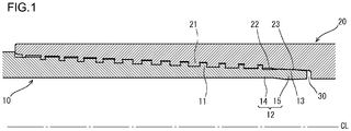
- FIG. 1 is a longitudinal sectional view of a threaded joint for steel pipes according to a first embodiment.
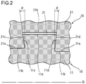
- FIG. 2 is a longitudinal sectional view showing a threaded portion in the threaded joint for steel pipes.
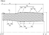
- FIG. 3 is a longitudinal sectional view showing an example of a free end region of the pin in the threaded joint for steel pipes.
- the threaded joint of the first embodiment is a coupling-type threaded joint employing wedge threads (dovetail-shaped tapered threads) and is constructed of a pin 10 and a box 20.
- the pin 10 includes, in order from the tubular body having the pin 10 toward the free end thereof: a male threaded portion 11; and a lip portion 12.
- the lip portion 12 extends continuously from the male threaded portion 11 along the pipe axis CL.
- the lip portion 12 is composed of, in order toward the free end of the pin 10: a neck portion 14; and a sealing head portion 15.
- the sealing head portion 15 includes a sealing surface 13.
- the box 20 includes, in order from the free end of the box 20 toward the tubular body thereof: a female threaded portion 21; and a recessed portion 22.
- the female threaded portion 21 is provided to correspond to the male threaded portion 11 of the pin 10.
- the recessed portion 22 is provided to correspond to the lip portion 12 of the pin 10.
- the recessed portion 22 includes a sealing surface 23 corresponding to the sealing surface 13 of the pin 10.
- the neck portion 14 of the pin 10 connects the male threaded portion 11 to the sealing head portion 15.
- the outer peripheral surface 14a of the neck portion 14 is a cylindrical surface (hereinafter also referred to as "neck outer peripheral cylindrical surface") whose central axis is the pipe axis CL.
- the inner peripheral surface 14b of the neck portion 14 includes a cylindrical surface 14ba (hereinafter also referred to as “neck inner peripheral cylindrical surface”) and tapered surface 14bb (hereinafter also referred to as “neck inner peripheral tapered surface”), with the former being located closer to the male threaded portion 11 and defining an inside diameter identical with that of the tubular body and the latter being located closer to the sealing head portion 15 and decreasing in diameter toward the free end of the pin 10.
- the neck inner peripheral cylindrical surface 14ba may not be provided.
- the outer peripheral surface 15a of the sealing head portion 15 includes a tapered surface 15aa (hereinafter also referred to as a "head outer peripheral inside tapered surface”) which is continuous with the outer peripheral surface 14a of the neck portion 14 and increases in diameter toward the free end of the pin 10.
- a cylindrical surface 15ab (hereinafter also referred to as "head outer peripheral cylindrical surface”) whose central axis is the pipe axis CL is continuous with the head outer peripheral inside tapered surface 15aa.
- the sealing surface 13 is continuous with the head outer peripheral cylindrical surface 15ab.
- the sealing surface 13 is composed of, for example, a curved surface 13a (hereinafter also referred to as “seal curved surface”) and a tapered surface 13b (hereinafter also referred to as “seal tapered surface”).
- the seal curved surface 13a is a surface that corresponds to a peripheral surface of a solid of revolution that can be obtained by rotating a curved line such as an arc about the pipe axis CL.
- the seal tapered surface 13b is a tapered surface which decreases in diameter toward the free end of the pin 10.
- the inner peripheral surface 15b of the sealing head portion 15 includes a tapered surface 15ba (hereinafter also referred to as “head inner peripheral inside tapered surface”) that is continuous with the neck inner peripheral tapered surface 14bb at the same taper angle.
- a cylindrical surface 15bb (hereinafter also referred to as “head inner peripheral cylindrical surface”) whose central axis is the pipe axis CL is continuous with the head inner peripheral inside tapered surface 15ba.
- a tapered surface 15bc (hereinafter also referred to as "head inner peripheral foremost tapered surface”) which slightly increases in diameter toward the free end of the pin 10 is continuous with the head inner peripheral cylindrical surface 15bb.
- the head inner peripheral inside tapered surface 15ba may not be provided. In such a case, the head inner peripheral cylindrical surface 15bb extends into the region of the neck portion 14 to be continuous with the neck inner peripheral tapered surface 14bb.
- the maximum outside diameter Di of the region of the sealing surface 13 in the sealing head portion 15 is larger than an outside diameter D 2 of the neck portion 14 at a boundary between the neck portion 14 and the male threaded portion 11.
- the boundary between the neck portion 14 and the male threaded portion 11 corresponds to the thread machining start point of the male threaded portion 11.
- the sealing head portion 15 has an inside diameter di smaller than the inside diameter do of the tubular body.
- the inside diameter di of the sealing head portion 15 is smallest in the region of the head inner peripheral cylindrical surface 15bb. This can be readily accomplished by swaging the free end region of the pin 10 in advance.
- the head inner peripheral foremost tapered surface 15bc and the head inner peripheral cylindrical surface 15bb are formed by machining after swaging.
- the neck inner peripheral tapered surface 14bb is an as-swaged surface or a machined surface depending on the specifications. Since the inside diameter di of the sealing head portion 15 is smaller than the inside diameter do of the tubular body, the wall thickness of the sealing head portion 15 can be sufficiently increased without the need to enlarge the outside diameter of the sealing head portion 15 to a great extent.
- the male threaded portion 11 of the pin 10 and the female threaded portion 21 of the box 20 are tapered threaded portions with dovetail threads (wedge threads) that can engage with each other.
- the load flanks 11c of the male threaded portion 11 and the load flanks 21c of the female threaded portion 21, and the stabbing flanks 11d of the male threaded portion 11 and the stabbing flanks 21d of the female threaded portion 21, each have a negative flank angle ⁇ in a range of about 1° to 10° with respect to the pipe axis CL.
- the male threaded portion 11 and the female threaded portion 21 are threadedly engageable with each other, and in a fastened state, the load flanks 11c and the load flanks 21c are in intimate contact with each other, and the stabbing flanks 11d and the stabbing flanks 21d are in intimate contact with each other, so that the threaded portions as a whole firmly engage with each other.
- the sealing surface 13 of the pin 10 and the sealing surface 23 of the box 20 are brought into contact with each other by the screwing of the pin 10 and, in a fastened state, they engage in intimate contact with each other to have an interference fit, so as to form an internal seal by surface-to-surface contact.
- the sealing head portion 15, which has the sealing surface 13 has an increased wall thickness, and therefore the region of the sealing surface 13 has increased stiffness.
- the internal seal effected by the sealing surface 13 provides high sealing performance. This is due to the fact that radially inward deformation is inhibited in the region of the sealing surface 13. It is noted that the internal seal provides, as its inherent function, high sealing performance against internal pressure as well.
- clearances 31 are provided between the crests 11a of the male threaded portion 11 and the roots 21b of the female threaded portion 21 in a fastened state. These clearances 31 prevent an abnormal increase in the dope pressure.
- the roots 11b of the male threaded portion 11 are in contact with the crests 21a of the female threaded portion 21. It is to be noted that clearances may be provided both between the crests 11a of the male threaded portion 11 and the roots 21b of the female threaded portion 21 and between the roots 11b of the male threaded portion 11 and the crests 21a of the female threaded portion 21.
- clearances may be provided solely between the roots 11b of the male threaded portion 11 and the crests 21 a of the female threaded portion 21.
- a preferred range of each clearance is from 0.05 to 0.5 mm. Within this range, a sufficient height of engagement between the male threaded portion 11 and the female threaded portion 21 can be ensured, so that high torque performance can be provided.
- the taper angles of the male threaded portion 11 and the female threaded portion 21 are each preferably in a range of 1° to 5° with respect to the pipe axis CL. If the taper angles of the threaded portions are too large, the lengths of the threaded portions are excessively shortened and therefore the torque resistance performance will be decreased. On the other hand, if the taper angles of the threaded portions are too small, the lengths of the threaded portions are excessively elongated and therefore the cost of manufacturing will be increased. A more preferred lower limit of the taper angles is 1.5° and a still more preferred lower limit thereof is 2°. A more preferred upper limit of the taper angles is 4°.
- the thread heights of the male threaded portion 11 and the female threaded portion 21 are each preferably in a range of 1.0 mm to 3.0 mm. If the thread heights are too high, the cost of manufacturing will be increased, and in addition, the sealing performance against internal pressure will be decreased because of the reduced wall thickness of the box 20. On the other hand, if the thread heights are too low, the torque resistance performance will be decreased.
- a more preferred lower limit of the thread heights is 1.2 mm and a still more preferred lower limit thereof is 1.5 mm.
- the wall thickness of the region of the sealing surface 13 at the position of the maximum outside diameter is preferably in a range of 55% to 80% of the wall thickness of the tubular body. If the wall thickness of the region of the sealing surface 13 is too thin, the sealing performance against external pressure cannot be ensured because the stiffness is decreased. On the other hand, if the wall thickness of the region of the sealing surface 13 is too large, the stiffness is increased.
- the increase of the wall thickness of the region of the sealing surface 13 is to be accomplished by enlarging the outside diameter of the sealing head portion 15, then the diameter of the sealing surface 23 of the box 20 is enlarged, and the resulting decrease in the wall thickness of the box 20 may cause a decrease in sealing performance against internal pressure.
- the increase of the wall thickness of the region of the sealing surface 13 is to be accomplished by reducing the inside diameter of the sealing head portion 15, then it is necessary to limit the inside diameter of the sealing head portion 15, particularly the inside diameter of the head inner peripheral cylindrical surface 15bb, to the inside diameter required by API specifications.
- the neck portion 14 which constitutes the lip portion 12 of the pin 10 preferably has a minimum wall thickness in a range of 45% to 70% of the wall thickness of the tubular body. If the minimum wall thickness of the neck portion 14 is too thin, the sealing performance against external pressure cannot be ensured because the stiffness of the neck portion 14 is decreased. On the other hand, if the minimum wall thickness of the neck portion 14 is too large, the thread machining start point is to be shifted to a position closer to the outer periphery of the pin 10, and therefore the thread height will have to be lowered or the lengths of the threaded portions will have to be shortened, with the result that the torque resistance performance of wedge threads is not exhibited.
- the head outer peripheral inside tapered surface 15aa which is adjacent to the outer peripheral surface 14a of the neck portion 14, has a taper angle in a range of 5° to 20° with respect to the pipe axis CL. If the taper angle of the head outer peripheral inside tapered surface 15aa is larger, the stiffness of the sealing surface 13 is increased as a result of the increased wall thickness of the sealing head portion 15, but the sealing performance against internal pressure will be decreased because of the reduced wall thickness of the box 20. On the other hand, if the taper angle of the head outer peripheral inside tapered surface 15aa is too small, the sealing performance against external pressure will be decreased because a sufficient wall thickness of the region of the sealing surface 13 cannot be provided.
- the head inner peripheral cylindrical surface 15bb (including the case in which it extends into the region of the neck portion 14) preferably has a length Li along the pipe axis CL of at least 3 mm.
- the length Li is a length extending from the boundary between the head inner peripheral foremost tapered surface 15bc and the head inner peripheral cylindrical surface 15bb.
- the head inner peripheral foremost tapered surface 15bc has a length L 2 along the pipe axis CL of about 8 to 12 mm. If the length Li of the head inner peripheral cylindrical surface 15bb is too short, the stiffness of the sealing head portion 15 is not sufficiently increased, and therefore the sealing performance against external pressure cannot be ensured.
- a preferred lower limit of the length Li is 4 mm.
- the length Li is preferably as long as possible. However, the length Li depends on the degree of swaging. Thus, a preferred upper limit of the length Li is 15 mm.
- the seal tapered surface 13b which constitutes the sealing surface 13 of the lip portion 12 preferably has a taper angle in a range of 3° to 10° with respect to the pipe axis CL. If the taper angle of the seal tapered surface 13b is larger, the stiffness is decreased in an end portion of the region of the sealing surface 13 as a result of the reduced wall thickness therein, and therefore the sealing performance against external pressure will be decreased. On the other hand, if the taper angle of the seal tapered surface 13b is too small, the sealing surfaces 13, 23 slide relative to each other when a tensile load is applied to the threaded joint, so that the contact between them may be lost.
- a clearance 30 is provided between the end face of the lip portion 12 of the pin 10 and the tubular body-side end of the recessed portion 22 of the box 20 (see FIG. 1 ).
- the clearance 30 is preferably in a range of 0.1 mm to 3.0 mm. Without the clearance 30, the end face of the pin 10 would inadvertently come into contact with the recessed portion 22 of the box 20 during fastening thread. As a result, the engagement between the male threaded portion 11 and the female threaded portion 21 becomes insufficient, and therefore the torque resistance performance cannot be obtained. On the other hand, if the clearance 30 is too large, turbulence of fluids flowing through the threaded joint can occur in the vicinity of the clearance 30, which can induce erosion.
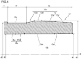
- FIG. 4 is a longitudinal sectional view showing an example of a free end region of the pin in the threaded joint for steel pipes according to the second embodiment.
- the threaded joint according to the second embodiment shown in FIG. 4 is a variation of the threaded joint according to the first embodiment shown in FIGS. 1 to 3 , and therefore descriptions redundant to those given in the first embodiment will not be repeated where appropriate.
- the neck inner peripheral tapered surface 14bb of the inner peripheral surface 14b of the neck portion 14 which constitutes the lip portion 12, is a tapered surface that increases in diameter toward the free end of the pin 10.
- the inside diameter di of the sealing head portion 15 is larger than the inside diameter do of the tubular body.
- the maximum outside diameter Di of the region of the sealing surface 13 in the sealing head portion 15 is larger than an outside diameter D 2 of the neck portion 14 at a boundary between the neck portion 14 and the male threaded portion 11. Consequently, the threaded joint of the second embodiment also produces advantageous effects similar to those of the first embodiment described above.
- an increase of the wall thickness of the region of the sealing surface 13 results in an enlargement of the outside diameter of the region of the sealing surface 13.
- the diameter of the sealing surface 23 of the box 20 is enlarged, and the resulting decrease in the wall thickness of the box 20 may cause a decrease in sealing performance against internal pressure.
- the first embodiment is more advantageous.
- the present invention is not limited to the embodiments described above, and various modifications may be made without departing from the scope of the present invention, as defined by the claims.
- the threaded joints according to the above embodiments may be employed not only as a coupling-type threaded joint but also as an integral-type threaded joint.
- Models for the FEM analysis were prepared based on coupling-type threaded joints for oil country tubular goods employing wedge threads.
- a model of the threaded joint of the first embodiment shown in FIGS. 1 to 3 was prepared.
- a model of a typical conventional threaded joint, in which the maximum outside diameter of the region of the sealing surface in the sealing head portion is smaller than the outside diameter of the neck portion at the thread machining start point was prepared.
- the representative dimensions of each model are shown in Table 1.
- the torque resistance performance was evaluated by using the values at the point of yielding (yield torque) in the torque chart and comparing the values.
- the sealing performance was evaluated by comparing the minimum values of the seal contact force of the sealing surfaces (the product of the average seal contact pressure and the seal contact width, of the sealing surfaces) in the internal pressure cycle (the first and second quadrants) and the external pressure cycle (the third and fourth quadrants) in the load sequence. (It is noted that the higher the minimum value of the average contact pressure, the better the sealing performance of the sealing surfaces.)
- FIG. 5 is a diagram showing the results of evaluation of torque resistance performance in Example 1.
- FIG. 6 is a diagram showing the results of evaluation of sealing performance in Example 1. As shown in FIG. 5 , high torque resistance performance was exhibited in both Inventive Example and Comparative Example. In Comparative Example, the contact between the sealing surfaces was lost as shown in FIG. 6 . In contrast, Inventive Example showed markedly improved sealing performance.
- Models for the FEM analysis were prepared based on coupling-type threaded joints for oil country tubular goods employing wedge threads, with the geometries of the lip portions varied based on the threaded joints of the first and second embodiments shown in FIGS. 1 to 4 .
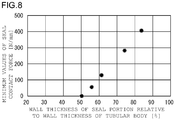
- the wall thickness of the region of the sealing surface at a position of the maximum outside diameter in the sealing head portion relative to the wall thickness of the tubular body was varied to provide five different levels of wall thickness, namely, 50%, 56%, 61%, 74% and 83%.
- the representative dimensions of each model are shown in Table 2.
- the models of Test Nos. 1 to 3 are based on the threaded joint of the second embodiment shown in FIG. 4 , each including a sealing head portion having an inside diameter larger than the inside diameter of the tubular body.
- the models of Test Nos. 4 and 5 are based on the threaded joint of the first embodiment shown in FIG. 3 , each including a sealing head portion having an inside diameter smaller than the inside diameter of the tubular body.
- Example 1 a load sequence which simulated that in an ISO 13679 Series A test was applied to each model in a fastened state, and the sealing performance was evaluated by comparing the minimum values of the seal contact force of the sealing surfaces.
- FIG. 8 is a diagram showing the results of evaluation of sealing performance in Example 2.
- the results shown in FIG. 8 demonstrate that, as the wall thickness of the seal portion relative to the wall thickness of the tubular body increases, i.e., the wall thickness of the lip portion increases, the sealing performance is improved.
- the wall thickness of the seal portion relative to the wall thickness of the tubular body is at least 55%, sufficient sealing performance is ensured.
- Models for the FEM analysis were prepared based on coupling-type threaded joints for oil country tubular goods employing wedge threads, with the geometries of the lip portions varied based on the threaded joint of the first embodiment shown in FIGS. 1 to 3 .
- the length of the head inner peripheral cylindrical surface was varied to provide four different levels of length, namely, 2 mm, 3 mm, 4 mm, and 5mm.
- the representative dimensions of each model are shown in Table 3.
- FIG. 10 is a diagram showing the results of evaluation of sealing performance in Example 3.
- the results shown in FIG. 10 demonstrate that, as the length of the head inner peripheral cylindrical surface increases, the sealing performance is improved. In particular, it is seen that, when the length of the head inner peripheral cylindrical surface is at least 3 mm, sufficient sealing performance is ensured.
- a threaded joint according to the present invention is capable of being effectively utilized in connecting steel pipes that are used for extraction, production, or transport of underground resources.
- underground resources include fossil fuels such as crude oil, natural gas, shale gas, and methane hydrate, and also include gas or liquid underground resources such as ground water and hot springs.
Landscapes
- Engineering & Computer Science (AREA)
- Mining & Mineral Resources (AREA)
- Life Sciences & Earth Sciences (AREA)
- Geology (AREA)
- Mechanical Engineering (AREA)
- General Engineering & Computer Science (AREA)
- Fluid Mechanics (AREA)
- Environmental & Geological Engineering (AREA)
- Physics & Mathematics (AREA)
- General Life Sciences & Earth Sciences (AREA)
- Geochemistry & Mineralogy (AREA)
- Non-Disconnectible Joints And Screw-Threaded Joints (AREA)
- Gasket Seals (AREA)
- Joints With Pressure Members (AREA)
- Earth Drilling (AREA)
Priority Applications (1)
| Application Number | Priority Date | Filing Date | Title |
|---|---|---|---|
| PL15809447T PL3159592T3 (pl) | 2014-06-20 | 2015-06-19 | Połączenie gwintowe do rur stalowych |
Applications Claiming Priority (2)
| Application Number | Priority Date | Filing Date | Title |
|---|---|---|---|
| JP2014127671 | 2014-06-20 | ||
| PCT/JP2015/003093 WO2015194193A1 (ja) | 2014-06-20 | 2015-06-19 | 鋼管用ねじ継手 |
Publications (3)
| Publication Number | Publication Date |
|---|---|
| EP3159592A1 EP3159592A1 (en) | 2017-04-26 |
| EP3159592A4 EP3159592A4 (en) | 2018-03-21 |
| EP3159592B1 true EP3159592B1 (en) | 2019-10-09 |
Family
ID=54935195
Family Applications (1)
| Application Number | Title | Priority Date | Filing Date |
|---|---|---|---|
| EP15809447.4A Active EP3159592B1 (en) | 2014-06-20 | 2015-06-19 | Threaded joint for steel pipes |
Country Status (13)
| Country | Link |
|---|---|
| US (1) | US10480693B2 (ja) |
| EP (1) | EP3159592B1 (ja) |
| JP (1) | JP6311019B2 (ja) |
| CN (1) | CN106461126B (ja) |
| AU (1) | AU2015275495B2 (ja) |
| BR (1) | BR112016028401B8 (ja) |
| CA (1) | CA2952386C (ja) |
| EA (1) | EA033015B1 (ja) |
| MX (1) | MX2016016919A (ja) |
| MY (1) | MY191387A (ja) |
| PL (1) | PL3159592T3 (ja) |
| UA (1) | UA117530C2 (ja) |
| WO (1) | WO2015194193A1 (ja) |
Families Citing this family (9)
| Publication number | Priority date | Publication date | Assignee | Title |
|---|---|---|---|---|
| JP6640347B2 (ja) * | 2016-06-08 | 2020-02-05 | 日本製鉄株式会社 | 鋼管用ねじ継手 |
| FR3060701A1 (fr) | 2016-12-16 | 2018-06-22 | Vallourec Oil And Gas France | Joint filete pour composant tubulaire |
| JP6955942B2 (ja) * | 2017-09-22 | 2021-10-27 | 株式会社Tft | 地山埋設鋼管 |
| PL3572612T3 (pl) * | 2018-05-25 | 2021-04-19 | Vallourec Oil And Gas France | Gwintowane połączenie rurowe |
| EP3572611B1 (en) * | 2018-05-25 | 2020-12-30 | Vallourec Oil And Gas France | Tubular threaded connection |
| WO2020075366A1 (ja) | 2018-10-11 | 2020-04-16 | 日本製鉄株式会社 | 鋼管用ねじ継手 |
| CN112469938B (zh) * | 2018-10-11 | 2022-09-20 | 日本制铁株式会社 | 钢管用螺纹接头 |
| JP7185059B2 (ja) | 2019-09-02 | 2022-12-06 | 日本製鉄株式会社 | 鋼管用ねじ継手 |
| PL3798409T3 (pl) * | 2019-09-24 | 2023-12-04 | Vallourec Oil And Gas France | Połączenie gwintowe obejmujące kołnierz pośredni |
Family Cites Families (25)
| Publication number | Priority date | Publication date | Assignee | Title |
|---|---|---|---|---|
| US5066052A (en) * | 1989-03-08 | 1991-11-19 | Baroid Technology, Inc. | Threaded pipe joint having improved seal ring entrapment |
| GB9706084D0 (en) * | 1997-03-24 | 1997-05-14 | Oil States Ind Uk Ltd | Improvements in and relating to pipe connectors |
| US7690696B2 (en) | 1999-04-19 | 2010-04-06 | Hydril Company | Wedge thread with torque shoulder |
| US6626471B2 (en) * | 2000-08-10 | 2003-09-30 | Hydril Company | Double flex seal for tubular connection |
| FR2820806B1 (fr) * | 2001-02-09 | 2004-02-20 | Vallourec Mannesmann Oil & Gas | Joint filete tubulaire avec face de filet bombee convexe |
| FR2844331B1 (fr) * | 2002-01-03 | 2004-11-26 | Vallourec Mannesmann Oil & Gas | Procede de realisation d'un joint tubulaire etanche avec expansion plastique |
| US6971685B2 (en) * | 2002-06-24 | 2005-12-06 | Weatherford/Lamb, Inc. | Multi-point high pressure seal for expandable tubular connections |
| FR2855587B1 (fr) * | 2003-05-30 | 2006-12-29 | Vallourec Mannesmann Oil & Gas | Joint filete tubulaire a serrage axial progressif des filets |
| US8220842B2 (en) * | 2003-05-30 | 2012-07-17 | Vallourec Mannesmann Oil & Gas France | Threaded tubular connection which is resistant to bending stresses |
| FR2863033B1 (fr) * | 2003-11-28 | 2007-05-11 | Vallourec Mannesmann Oil & Gas | Realisation, par expansion plastique, d'un joint tubulaire etanche avec surface(s) de butee inclinee(s) |
| FR2863031B1 (fr) * | 2003-11-28 | 2006-10-06 | Vallourec Mannesmann Oil & Gas | Realisation, par expansion plastique, d'un assemblage de deux joints tubulaires filetes etanches avec une sous-epaisseur de matiere locale et initiale |
| FR2863029B1 (fr) * | 2003-11-28 | 2006-07-07 | Vallourec Mannesmann Oil & Gas | Realisation, par expansion plastique, d'un joint tubulaire etanche avec surepaisseur(s) de matiere locale(s) initiale(s) |
| US7585002B2 (en) * | 2004-04-21 | 2009-09-08 | Baker Hughes Incorporated | Expandable tubular connection |
| FR2874988B1 (fr) | 2004-09-09 | 2008-05-02 | Vallourec Mannesmann Oil & Gas | Element male pour un joint filete tubulaire etanche apres expansion diametrale |
| US7717478B2 (en) * | 2006-08-29 | 2010-05-18 | Hydril Llc | Scalloped wedge threads |
| US8668233B2 (en) * | 2004-12-30 | 2014-03-11 | Hydril Company | Threaded connection with perturbed flanks |
| US8177262B2 (en) | 2005-07-28 | 2012-05-15 | Hydril Company Lp | Mid-seal for expandable connections |
| FR2889727B1 (fr) * | 2005-08-09 | 2007-09-28 | Vallourec Mannesmann Oil Gas F | Joint filete tubulaire etanche aux liquides et aux gaz |
| US7798536B2 (en) * | 2005-08-11 | 2010-09-21 | Weatherford/Lamb, Inc. | Reverse sliding seal for expandable tubular connections |
| FR2913746B1 (fr) * | 2007-03-14 | 2011-06-24 | Vallourec Mannesmann Oil & Gas | Joint filete tubulaire etanche pour sollicitations de pression interieure et exterieure |
| WO2009060552A1 (en) * | 2007-11-08 | 2009-05-14 | Sumitomo Metal Industries, Ltd. | Threaded joint for steel pipes |
| CN202039782U (zh) * | 2011-04-08 | 2011-11-16 | 无锡西姆莱斯石油专用管制造有限公司 | 一种抗弯曲的套管螺纹连接结构 |
| JP5978953B2 (ja) | 2012-11-26 | 2016-08-24 | Jfeスチール株式会社 | 管用ねじ継手 |
| WO2014151886A2 (en) * | 2013-03-15 | 2014-09-25 | Weatherford/Lamb, Inc. | Couplings for expandable tubular |
| US10428594B2 (en) * | 2013-11-22 | 2019-10-01 | Vetco Gray, LLC | Alignment guide feature for metal to metal seal protection on mechanical connections and couplings |
-
2015
- 2015-06-19 CA CA2952386A patent/CA2952386C/en active Active
- 2015-06-19 BR BR112016028401A patent/BR112016028401B8/pt active Search and Examination
- 2015-06-19 PL PL15809447T patent/PL3159592T3/pl unknown
- 2015-06-19 WO PCT/JP2015/003093 patent/WO2015194193A1/ja active Application Filing
- 2015-06-19 US US15/317,418 patent/US10480693B2/en active Active
- 2015-06-19 EA EA201692429A patent/EA033015B1/ru not_active IP Right Cessation
- 2015-06-19 EP EP15809447.4A patent/EP3159592B1/en active Active
- 2015-06-19 MY MYPI2016704507A patent/MY191387A/en unknown
- 2015-06-19 CN CN201580032656.4A patent/CN106461126B/zh active Active
- 2015-06-19 MX MX2016016919A patent/MX2016016919A/es active IP Right Grant
- 2015-06-19 JP JP2016529069A patent/JP6311019B2/ja active Active
- 2015-06-19 AU AU2015275495A patent/AU2015275495B2/en active Active
- 2015-06-19 UA UAA201700345A patent/UA117530C2/uk unknown
Non-Patent Citations (1)
| Title |
|---|
| None * |
Also Published As
| Publication number | Publication date |
|---|---|
| CN106461126A (zh) | 2017-02-22 |
| JP6311019B2 (ja) | 2018-04-11 |
| EA033015B1 (ru) | 2019-08-30 |
| MY191387A (en) | 2022-06-22 |
| WO2015194193A1 (ja) | 2015-12-23 |
| EP3159592A4 (en) | 2018-03-21 |
| US10480693B2 (en) | 2019-11-19 |
| BR112016028401B1 (pt) | 2021-05-18 |
| JPWO2015194193A1 (ja) | 2017-04-20 |
| CA2952386C (en) | 2018-10-30 |
| AU2015275495B2 (en) | 2018-02-22 |
| EA201692429A1 (ru) | 2017-03-31 |
| MX2016016919A (es) | 2017-04-27 |
| BR112016028401A2 (pt) | 2017-08-22 |
| AU2015275495A1 (en) | 2017-02-09 |
| CA2952386A1 (en) | 2015-12-23 |
| BR112016028401B8 (pt) | 2021-08-10 |
| PL3159592T3 (pl) | 2020-11-02 |
| UA117530C2 (uk) | 2018-08-10 |
| CN106461126B (zh) | 2018-12-21 |
| EP3159592A1 (en) | 2017-04-26 |
| US20170108151A1 (en) | 2017-04-20 |
Similar Documents
| Publication | Publication Date | Title |
|---|---|---|
| EP3159592B1 (en) | Threaded joint for steel pipes | |
| EP3205918B1 (en) | Threaded joint for steel pipes | |
| EP3159591B1 (en) | Threaded joint for steel pipes | |
| EP3093543B2 (en) | Threaded joint for steel pipe | |
| EP3043098B1 (en) | Threaded connection for steel pipe | |
| EP3366968B1 (en) | Threaded fitting for steel pipes | |
| EP3604881B1 (en) | Threaded connection for steel pipe | |
| CA3015307C (en) | Threaded joint for steel pipes | |
| EP3409991B1 (en) | Threaded joint for steel pipe | |
| AU2016373923A1 (en) | Threaded joint for steel pipe | |
| AU2020327779B2 (en) | Threaded connection for steel pipe | |
| US20230146768A1 (en) | Threaded connection for steel pipe | |
| EP4036449B1 (en) | Threaded connection | |
| OA18134A (en) | Threaded coupling for steel piping | |
| EP3633255B1 (en) | Threaded connection for steel pipes | |
| OA20943A (en) | Threaded coupling for steel pipe | |
| OA18648A (en) | Threaded fitting for steel pipes. |
Legal Events
| Date | Code | Title | Description |
|---|---|---|---|
| STAA | Information on the status of an ep patent application or granted ep patent |
Free format text: STATUS: THE INTERNATIONAL PUBLICATION HAS BEEN MADE |
|
| PUAI | Public reference made under article 153(3) epc to a published international application that has entered the european phase |
Free format text: ORIGINAL CODE: 0009012 |
|
| STAA | Information on the status of an ep patent application or granted ep patent |
Free format text: STATUS: REQUEST FOR EXAMINATION WAS MADE |
|
| 17P | Request for examination filed |
Effective date: 20161207 |
|
| AK | Designated contracting states |
Kind code of ref document: A1 Designated state(s): AL AT BE BG CH CY CZ DE DK EE ES FI FR GB GR HR HU IE IS IT LI LT LU LV MC MK MT NL NO PL PT RO RS SE SI SK SM TR |
|
| AX | Request for extension of the european patent |
Extension state: BA ME |
|
| DAV | Request for validation of the european patent (deleted) | ||
| DAX | Request for extension of the european patent (deleted) | ||
| A4 | Supplementary search report drawn up and despatched |
Effective date: 20180221 |
|
| RIC1 | Information provided on ipc code assigned before grant |
Ipc: F16L 15/04 20060101AFI20180215BHEP Ipc: E21B 17/042 20060101ALI20180215BHEP |
|
| GRAP | Despatch of communication of intention to grant a patent |
Free format text: ORIGINAL CODE: EPIDOSNIGR1 |
|
| STAA | Information on the status of an ep patent application or granted ep patent |
Free format text: STATUS: GRANT OF PATENT IS INTENDED |
|
| INTG | Intention to grant announced |
Effective date: 20190605 |
|
| GRAS | Grant fee paid |
Free format text: ORIGINAL CODE: EPIDOSNIGR3 |
|
| RAP1 | Party data changed (applicant data changed or rights of an application transferred) |
Owner name: NIPPON STEEL CORPORATION Owner name: VALLOUREC OIL AND GAS FRANCE |
|
| GRAA | (expected) grant |
Free format text: ORIGINAL CODE: 0009210 |
|
| STAA | Information on the status of an ep patent application or granted ep patent |
Free format text: STATUS: THE PATENT HAS BEEN GRANTED |
|
| AK | Designated contracting states |
Kind code of ref document: B1 Designated state(s): AL AT BE BG CH CY CZ DE DK EE ES FI FR GB GR HR HU IE IS IT LI LT LU LV MC MK MT NL NO PL PT RO RS SE SI SK SM TR |
|
| REG | Reference to a national code |
Ref country code: GB Ref legal event code: FG4D |
|
| REG | Reference to a national code |
Ref country code: CH Ref legal event code: EP |
|
| REG | Reference to a national code |
Ref country code: IE Ref legal event code: FG4D |
|
| REG | Reference to a national code |
Ref country code: DE Ref legal event code: R096 Ref document number: 602015039580 Country of ref document: DE |
|
| REG | Reference to a national code |
Ref country code: AT Ref legal event code: REF Ref document number: 1189232 Country of ref document: AT Kind code of ref document: T Effective date: 20191115 |
|
| REG | Reference to a national code |
Ref country code: RO Ref legal event code: EPE |
|
| REG | Reference to a national code |
Ref country code: NL Ref legal event code: FP |
|
| REG | Reference to a national code |
Ref country code: NO Ref legal event code: T2 Effective date: 20191009 |
|
| REG | Reference to a national code |
Ref country code: LT Ref legal event code: MG4D |
|
| PG25 | Lapsed in a contracting state [announced via postgrant information from national office to epo] |
Ref country code: LT Free format text: LAPSE BECAUSE OF FAILURE TO SUBMIT A TRANSLATION OF THE DESCRIPTION OR TO PAY THE FEE WITHIN THE PRESCRIBED TIME-LIMIT Effective date: 20191009 Ref country code: SE Free format text: LAPSE BECAUSE OF FAILURE TO SUBMIT A TRANSLATION OF THE DESCRIPTION OR TO PAY THE FEE WITHIN THE PRESCRIBED TIME-LIMIT Effective date: 20191009 Ref country code: BG Free format text: LAPSE BECAUSE OF FAILURE TO SUBMIT A TRANSLATION OF THE DESCRIPTION OR TO PAY THE FEE WITHIN THE PRESCRIBED TIME-LIMIT Effective date: 20200109 Ref country code: FI Free format text: LAPSE BECAUSE OF FAILURE TO SUBMIT A TRANSLATION OF THE DESCRIPTION OR TO PAY THE FEE WITHIN THE PRESCRIBED TIME-LIMIT Effective date: 20191009 Ref country code: GR Free format text: LAPSE BECAUSE OF FAILURE TO SUBMIT A TRANSLATION OF THE DESCRIPTION OR TO PAY THE FEE WITHIN THE PRESCRIBED TIME-LIMIT Effective date: 20200110 Ref country code: PT Free format text: LAPSE BECAUSE OF FAILURE TO SUBMIT A TRANSLATION OF THE DESCRIPTION OR TO PAY THE FEE WITHIN THE PRESCRIBED TIME-LIMIT Effective date: 20200210 Ref country code: LV Free format text: LAPSE BECAUSE OF FAILURE TO SUBMIT A TRANSLATION OF THE DESCRIPTION OR TO PAY THE FEE WITHIN THE PRESCRIBED TIME-LIMIT Effective date: 20191009 Ref country code: ES Free format text: LAPSE BECAUSE OF FAILURE TO SUBMIT A TRANSLATION OF THE DESCRIPTION OR TO PAY THE FEE WITHIN THE PRESCRIBED TIME-LIMIT Effective date: 20191009 |
|
| PG25 | Lapsed in a contracting state [announced via postgrant information from national office to epo] |
Ref country code: RS Free format text: LAPSE BECAUSE OF FAILURE TO SUBMIT A TRANSLATION OF THE DESCRIPTION OR TO PAY THE FEE WITHIN THE PRESCRIBED TIME-LIMIT Effective date: 20191009 Ref country code: HR Free format text: LAPSE BECAUSE OF FAILURE TO SUBMIT A TRANSLATION OF THE DESCRIPTION OR TO PAY THE FEE WITHIN THE PRESCRIBED TIME-LIMIT Effective date: 20191009 Ref country code: IS Free format text: LAPSE BECAUSE OF FAILURE TO SUBMIT A TRANSLATION OF THE DESCRIPTION OR TO PAY THE FEE WITHIN THE PRESCRIBED TIME-LIMIT Effective date: 20200224 |
|
| PG25 | Lapsed in a contracting state [announced via postgrant information from national office to epo] |
Ref country code: AL Free format text: LAPSE BECAUSE OF FAILURE TO SUBMIT A TRANSLATION OF THE DESCRIPTION OR TO PAY THE FEE WITHIN THE PRESCRIBED TIME-LIMIT Effective date: 20191009 |
|
| REG | Reference to a national code |
Ref country code: DE Ref legal event code: R097 Ref document number: 602015039580 Country of ref document: DE |
|
| PG2D | Information on lapse in contracting state deleted |
Ref country code: IS |
|
| PG25 | Lapsed in a contracting state [announced via postgrant information from national office to epo] |
Ref country code: EE Free format text: LAPSE BECAUSE OF FAILURE TO SUBMIT A TRANSLATION OF THE DESCRIPTION OR TO PAY THE FEE WITHIN THE PRESCRIBED TIME-LIMIT Effective date: 20191009 Ref country code: DK Free format text: LAPSE BECAUSE OF FAILURE TO SUBMIT A TRANSLATION OF THE DESCRIPTION OR TO PAY THE FEE WITHIN THE PRESCRIBED TIME-LIMIT Effective date: 20191009 Ref country code: IS Free format text: LAPSE BECAUSE OF FAILURE TO SUBMIT A TRANSLATION OF THE DESCRIPTION OR TO PAY THE FEE WITHIN THE PRESCRIBED TIME-LIMIT Effective date: 20200209 |
|
| PLBE | No opposition filed within time limit |
Free format text: ORIGINAL CODE: 0009261 |
|
| STAA | Information on the status of an ep patent application or granted ep patent |
Free format text: STATUS: NO OPPOSITION FILED WITHIN TIME LIMIT |
|
| PG25 | Lapsed in a contracting state [announced via postgrant information from national office to epo] |
Ref country code: SM Free format text: LAPSE BECAUSE OF FAILURE TO SUBMIT A TRANSLATION OF THE DESCRIPTION OR TO PAY THE FEE WITHIN THE PRESCRIBED TIME-LIMIT Effective date: 20191009 Ref country code: SK Free format text: LAPSE BECAUSE OF FAILURE TO SUBMIT A TRANSLATION OF THE DESCRIPTION OR TO PAY THE FEE WITHIN THE PRESCRIBED TIME-LIMIT Effective date: 20191009 |
|
| 26N | No opposition filed |
Effective date: 20200710 |
|
| REG | Reference to a national code |
Ref country code: AT Ref legal event code: UEP Ref document number: 1189232 Country of ref document: AT Kind code of ref document: T Effective date: 20191009 |
|
| PG25 | Lapsed in a contracting state [announced via postgrant information from national office to epo] |
Ref country code: SI Free format text: LAPSE BECAUSE OF FAILURE TO SUBMIT A TRANSLATION OF THE DESCRIPTION OR TO PAY THE FEE WITHIN THE PRESCRIBED TIME-LIMIT Effective date: 20191009 |
|
| PG25 | Lapsed in a contracting state [announced via postgrant information from national office to epo] |
Ref country code: MC Free format text: LAPSE BECAUSE OF FAILURE TO SUBMIT A TRANSLATION OF THE DESCRIPTION OR TO PAY THE FEE WITHIN THE PRESCRIBED TIME-LIMIT Effective date: 20191009 |
|
| REG | Reference to a national code |
Ref country code: CH Ref legal event code: PL |
|
| PG25 | Lapsed in a contracting state [announced via postgrant information from national office to epo] |
Ref country code: LU Free format text: LAPSE BECAUSE OF NON-PAYMENT OF DUE FEES Effective date: 20200619 |
|
| REG | Reference to a national code |
Ref country code: BE Ref legal event code: MM Effective date: 20200630 |
|
| PG25 | Lapsed in a contracting state [announced via postgrant information from national office to epo] |
Ref country code: CH Free format text: LAPSE BECAUSE OF NON-PAYMENT OF DUE FEES Effective date: 20200630 Ref country code: IE Free format text: LAPSE BECAUSE OF NON-PAYMENT OF DUE FEES Effective date: 20200619 Ref country code: LI Free format text: LAPSE BECAUSE OF NON-PAYMENT OF DUE FEES Effective date: 20200630 |
|
| PG25 | Lapsed in a contracting state [announced via postgrant information from national office to epo] |
Ref country code: BE Free format text: LAPSE BECAUSE OF NON-PAYMENT OF DUE FEES Effective date: 20200630 |
|
| PG25 | Lapsed in a contracting state [announced via postgrant information from national office to epo] |
Ref country code: TR Free format text: LAPSE BECAUSE OF FAILURE TO SUBMIT A TRANSLATION OF THE DESCRIPTION OR TO PAY THE FEE WITHIN THE PRESCRIBED TIME-LIMIT Effective date: 20191009 Ref country code: MT Free format text: LAPSE BECAUSE OF FAILURE TO SUBMIT A TRANSLATION OF THE DESCRIPTION OR TO PAY THE FEE WITHIN THE PRESCRIBED TIME-LIMIT Effective date: 20191009 Ref country code: CY Free format text: LAPSE BECAUSE OF FAILURE TO SUBMIT A TRANSLATION OF THE DESCRIPTION OR TO PAY THE FEE WITHIN THE PRESCRIBED TIME-LIMIT Effective date: 20191009 |
|
| PG25 | Lapsed in a contracting state [announced via postgrant information from national office to epo] |
Ref country code: MK Free format text: LAPSE BECAUSE OF FAILURE TO SUBMIT A TRANSLATION OF THE DESCRIPTION OR TO PAY THE FEE WITHIN THE PRESCRIBED TIME-LIMIT Effective date: 20191009 |
|
| PGFP | Annual fee paid to national office [announced via postgrant information from national office to epo] |
Ref country code: RO Payment date: 20230608 Year of fee payment: 9 Ref country code: NO Payment date: 20230622 Year of fee payment: 9 Ref country code: NL Payment date: 20230620 Year of fee payment: 9 Ref country code: FR Payment date: 20230630 Year of fee payment: 9 Ref country code: DE Payment date: 20230620 Year of fee payment: 9 Ref country code: CZ Payment date: 20230612 Year of fee payment: 9 |
|
| PGFP | Annual fee paid to national office [announced via postgrant information from national office to epo] |
Ref country code: PL Payment date: 20230530 Year of fee payment: 9 Ref country code: AT Payment date: 20230621 Year of fee payment: 9 |
|
| PGFP | Annual fee paid to national office [announced via postgrant information from national office to epo] |
Ref country code: IT Payment date: 20230623 Year of fee payment: 9 Ref country code: GB Payment date: 20230622 Year of fee payment: 9 |
|
| PGFP | Annual fee paid to national office [announced via postgrant information from national office to epo] |
Ref country code: FR Payment date: 20230721 Year of fee payment: 9 |