EP3159479B1 - Verfahren zur montage eines rotorpakets - Google Patents
Verfahren zur montage eines rotorpakets Download PDFInfo
- Publication number
- EP3159479B1 EP3159479B1 EP16182498.2A EP16182498A EP3159479B1 EP 3159479 B1 EP3159479 B1 EP 3159479B1 EP 16182498 A EP16182498 A EP 16182498A EP 3159479 B1 EP3159479 B1 EP 3159479B1
- Authority
- EP
- European Patent Office
- Prior art keywords
- parts
- runout
- estimate
- stack
- assembling
- Prior art date
- Legal status (The legal status is an assumption and is not a legal conclusion. Google has not performed a legal analysis and makes no representation as to the accuracy of the status listed.)
- Active
Links
Images



Classifications
-
- F—MECHANICAL ENGINEERING; LIGHTING; HEATING; WEAPONS; BLASTING
- F01—MACHINES OR ENGINES IN GENERAL; ENGINE PLANTS IN GENERAL; STEAM ENGINES
- F01D—NON-POSITIVE DISPLACEMENT MACHINES OR ENGINES, e.g. STEAM TURBINES
- F01D5/00—Blades; Blade-carrying members; Heating, heat-insulating, cooling or antivibration means on the blades or the members
- F01D5/02—Blade-carrying members, e.g. rotors
- F01D5/027—Arrangements for balancing
-
- F—MECHANICAL ENGINEERING; LIGHTING; HEATING; WEAPONS; BLASTING
- F16—ENGINEERING ELEMENTS AND UNITS; GENERAL MEASURES FOR PRODUCING AND MAINTAINING EFFECTIVE FUNCTIONING OF MACHINES OR INSTALLATIONS; THERMAL INSULATION IN GENERAL
- F16F—SPRINGS; SHOCK-ABSORBERS; MEANS FOR DAMPING VIBRATION
- F16F15/00—Suppression of vibrations in systems; Means or arrangements for avoiding or reducing out-of-balance forces, e.g. due to motion
- F16F15/20—Suppression of vibrations of rotating systems by favourable grouping or relative arrangements of the moving members of the system or systems
-
- F—MECHANICAL ENGINEERING; LIGHTING; HEATING; WEAPONS; BLASTING
- F16—ENGINEERING ELEMENTS AND UNITS; GENERAL MEASURES FOR PRODUCING AND MAINTAINING EFFECTIVE FUNCTIONING OF MACHINES OR INSTALLATIONS; THERMAL INSULATION IN GENERAL
- F16F—SPRINGS; SHOCK-ABSORBERS; MEANS FOR DAMPING VIBRATION
- F16F15/00—Suppression of vibrations in systems; Means or arrangements for avoiding or reducing out-of-balance forces, e.g. due to motion
- F16F15/22—Compensation of inertia forces
-
- F—MECHANICAL ENGINEERING; LIGHTING; HEATING; WEAPONS; BLASTING
- F05—INDEXING SCHEMES RELATING TO ENGINES OR PUMPS IN VARIOUS SUBCLASSES OF CLASSES F01-F04
- F05D—INDEXING SCHEME FOR ASPECTS RELATING TO NON-POSITIVE-DISPLACEMENT MACHINES OR ENGINES, GAS-TURBINES OR JET-PROPULSION PLANTS
- F05D2220/00—Application
- F05D2220/30—Application in turbines
- F05D2220/32—Application in turbines in gas turbines
-
- F—MECHANICAL ENGINEERING; LIGHTING; HEATING; WEAPONS; BLASTING
- F05—INDEXING SCHEMES RELATING TO ENGINES OR PUMPS IN VARIOUS SUBCLASSES OF CLASSES F01-F04
- F05D—INDEXING SCHEME FOR ASPECTS RELATING TO NON-POSITIVE-DISPLACEMENT MACHINES OR ENGINES, GAS-TURBINES OR JET-PROPULSION PLANTS
- F05D2230/00—Manufacture
- F05D2230/50—Building or constructing in particular ways
- F05D2230/52—Building or constructing in particular ways using existing or "off the shelf" parts, e.g. using standardized turbocharger elements
-
- F—MECHANICAL ENGINEERING; LIGHTING; HEATING; WEAPONS; BLASTING
- F05—INDEXING SCHEMES RELATING TO ENGINES OR PUMPS IN VARIOUS SUBCLASSES OF CLASSES F01-F04
- F05D—INDEXING SCHEME FOR ASPECTS RELATING TO NON-POSITIVE-DISPLACEMENT MACHINES OR ENGINES, GAS-TURBINES OR JET-PROPULSION PLANTS
- F05D2260/00—Function
- F05D2260/81—Modelling or simulation
-
- F—MECHANICAL ENGINEERING; LIGHTING; HEATING; WEAPONS; BLASTING
- F05—INDEXING SCHEMES RELATING TO ENGINES OR PUMPS IN VARIOUS SUBCLASSES OF CLASSES F01-F04
- F05D—INDEXING SCHEME FOR ASPECTS RELATING TO NON-POSITIVE-DISPLACEMENT MACHINES OR ENGINES, GAS-TURBINES OR JET-PROPULSION PLANTS
- F05D2260/00—Function
- F05D2260/96—Preventing, counteracting or reducing vibration or noise
Definitions
- the disclosure relates to a method of assembling a rotor stack particularly, although not exclusively, for use in a gas turbine engine.
- Rotating components must be properly assembled and balanced in order to minimise vibrations. This is particularly important where the components rotate at high speeds, as is the case with the components of a gas turbine engine.
- abutting surfaces of component parts may exhibit swash (distortion from a plane normal to the part axis) which can lead to runout (perpendicular distance of the part axis from the central build axis) when the parts are assembled. This issue is exacerbated when a plurality of parts are assembled in a stack.
- Published European Patent Application EP 2019 185 discloses a method of balancing an assembly of rotary parts of a gas turbine engine, the method comprising measuring at least one of the concentricity and parallelism of each component and considering globally all possible component stacking positions to generate an optimised stacking position for each component of the assembly to minimise assembly imbalance.
- the disclosure seeks to provide a method which overcomes or alleviates the problems of prior methods.
- a method of assembling a rotor stack comprising a plurality of component parts, the method comprising: determining swash measurements for interfacing surfaces of the plurality of parts; calculating a runout estimate for a plurality of relative orientations of the parts; applying an optimisation algorithm to identify an optimal orientation from the plurality of relative orientations based on the runout estimates; and assembling the parts in the optimal orientation; wherein at least one of the plurality of parts is selected from an inventory of available parts; characterised in that calculating the runout estimate comprises estimating deformation of the parts as a function of clamping load and in that the runout estimate is compared with a threshold value, and if it falls outside of the threshold value, a different combination of parts is selected.
- the method may further comprise identifying a plurality of combinations of parts from the inventory of available parts which fall within the threshold value.
- a likelihood of success value may be provided based on an uncertainty and the proximity to the threshold.
- a message may be generated containing instructions for assembling the parts.
- Calculating the runout estimate may comprise augmenting the swash measurements using a neural network (or another appropriate statistical curve fit) to estimate the contact points between the interfacing surfaces.
- the runout estimation and the optimal orientation may be calculated for individual joints and/or the overall stack.
- the optimisation algorithm may be modified by user-defined settings.
- component parts are connected to one another to form a (rotor) stack which rotates during operation of the engine.
- Adjacent parts in the stack are connected to one another via abutting surfaces.
- the adjacent ends of the parts may each be provided with a flange comprising a plurality of boltholes.
- the flanges may be brought into contact with one another such that the boltholes of the respective flanges are aligned and are bolted to one another.
- Figure 1 shows a method of assembling the rotor stack from an inventory of component parts.
- step S2 swash measurements are obtained for each of the components parts in the inventory. These measurements may be taken at the time of manufacturing the parts and/or prior to assembly (i.e. when delivered into stock). Specifically, the abutting surfaces of the parts (e.g. the flanges) are measured to determine any deviations from the proper dimensions generated during manufacturing. These measurements may be stored on a suitable storage medium for subsequent use.
- step S4 a virtual stack of two adjacent parts selected from the inventory of parts is generated using the swash measurements from S2.
- the raw swash measurements may be augmented using neural networks or other suitable statistical curve fitting systems to provide an array of x, y, z points describing the possible contact surfaces of each part.
- the virtual stack provides an indication of the runout resulting from the swash associated with the abutting surfaces.
- the virtual stack takes into account deformation of the abutting surfaces generated by the clamping of the two parts together.
- the flange of part A may deviate significantly from the flange of part B.
- the flange of part A is sufficiently flexible that, when clamped, it conforms to the flange of part B.
- the initial swash measurements are altered by the deformation of the parts when at the required clamping loads (bolt torques). The user may thus enter the required torque for the bolts or this may be preconfigured.
- the runout estimation may also take into account the flexibility of the parts along their lengths and any external support of the parts which may limit runout.
- a rotation matrix is then applied in step S6, such as the rotation matrix R below:
- R cos ⁇ + u x 2 1 ⁇ cos ⁇ u x u y 1 ⁇ cos ⁇ ⁇ u z sin ⁇ ⁇ u x u z 1 ⁇ cos ⁇ + u y sin ⁇ ⁇ u y u x 1 ⁇ cos ⁇ + u z sin ⁇ ⁇ cos ⁇ ⁇ + u y 2 1 ⁇ cos ⁇ u y u z 1 ⁇ cos ⁇ ⁇ u x sin ⁇ ⁇ u z u x 1 ⁇ cos ⁇ ⁇ u y sin ⁇ ⁇ u z u y 1 ⁇ cos ⁇ + u x sin ⁇ ⁇ cos ⁇ + u z 2 1 ⁇ cos ⁇ cos ⁇ + u x sin ⁇ ⁇ cos ⁇ + u z 2 1 ⁇ cos
- the rotation matrix R changes the relative orientation between the two parts. Specifically, the rotation matrix R adjusts the components of a vector (u x ,u y ,u z ) describing the orientation of a reference plane from which the x, y, z components are defined.
- the connection between the parts may dictate that only specific orientations are possible. For example, the parts may be assembled in a fixed number of orientations based on the number of boltholes provided in the flanges. The rotation matrix R may thus simulate assembling the parts in every possible orientation. For each position, the runout is again estimated.
- the steps S2 to S6 are repeated for each interface in the rotor stack.
- step S8 an optimal solution is identified from the various permutations of the selected parts.
- step S10 it is determined whether the optimal solution for the stack of selected parts exhibits runout which falls within acceptable levels.
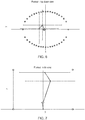
- Figures 4 and 5 show the runout for the stack of parts. Specifically, Figure 4 shows the runout in a top down view. In this Figure, the dotted circle represents a threshold runout for the stack. Each leg of the line shows the runout vector associated with each part, with the dots connecting the lines indicating the rotation axis of each part. Figure 5 shows the runout in a side view. In a similar manner to Figure 4 , the dotted square (only the four corners are shown) represents a threshold runout for the stack. Again, each leg of the line shows the runout vector associated with each part, with the dots connecting the lines indicating the rotation axis of each part. The accumulated runout must therefore lie within the threshold in order for the stack to be acceptable.
- steps S2 to S10 are repeated for a different selection of parts until an acceptable selection of parts are generated.
- Figures 6 and 7 show the accumulated runout for a second selection of parts which falls within the thresholds and thus is acceptable.
- the method may also provide an estimation of the vibration exhibited by the rotor during operation of the engine.
- a message (or other notification) is generated at S12 which identifies (using a part number or the like) the required parts for the stack and instructions for assembling the parts (i.e. their relative orientations).
- the stack can therefore be assembled without any intermediate measurements, thus reducing the assembly time.
- the process may be repeated to identify a plurality of acceptable rotor stacks which may be assembled using the available inventory of parts.
- the method may be optimised in order to maximise the number of rotor stacks which can be manufactured from the available parts.
- the method may also identify parts which cannot yet be used based on the available parts for the other positions in the stack.
- the optimisation algorithm may be setup to achieve a pre-defined balance between snugness of fit between the two components (characterised by standard deviation of the gap between them) and the runout that Part B produces relative to Part A.
- the correct balance may be defined by vibration dynamics considerations, which take into account the locations of bearings, mass distributions or other physical factors.
- the optimisation may also take into account the different operating conditions of the engine. Considerations of alignment include bearing alignment, mass distribution, runout, swash, blade tip rub, vibration modes etc.
- the optimisation of the whole rotor stack thus need not be based solely on absolute runout of the stack and may be optimised for other attributes, which may be selected by a user. For example, a part within the stack may be housed by a bearing and thus a larger amount of overall runout may be accepted in order to reduce the runout at this part, thereby reducing wear of the bearing.
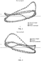
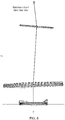
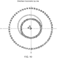
- Figures 8 to 10 show the deformation of the parts in the stack when assembled to one another.
- the contact points (calculated from the neural network) between the two mating surfaces are identified by finding the minimum gap location when the first derivative of the gap function changes sign from negative to positive.
- the clamping deformation is calculated through finite element analysis under the prescribed assembly loads (a statistical approach can be used to account for uncertainties in the joint) and then applied to the curve fitted on the mating surfaces of the parts as a function of the distance from the closest contact point.
- the deformation imposed by the clamping load cannot be larger than the initial surfaces' distance; once the gap is closed under clamping load the two surfaces are in contact and so further deformation is not allowed.
- the actual deformation of the mating surfaces is then applied on the following joint surface of the component through deformation correlations from computer finite element analysis which thus has a knock-on effect on the swash and concentricity of the mating surfaces of the next joint. This is repeated for each joint in the stack.
- an elastic microstructure deformation model which takes into account individual grain orientation may be utilised.
Landscapes
- Engineering & Computer Science (AREA)
- General Engineering & Computer Science (AREA)
- Mechanical Engineering (AREA)
- Physics & Mathematics (AREA)
- Acoustics & Sound (AREA)
- Aviation & Aerospace Engineering (AREA)
- Turbine Rotor Nozzle Sealing (AREA)
Claims (8)
- Verfahren zur Montage eines Rotorpakets, umfassend eine Vielzahl von Komponententeilen, wobei das Verfahren umfasst:Bestimmen (S2) von Taumelmessungen für Berührungsflächen der Vielzahl von Teilen;Berechnen (S4) einer Rundlaufschätzung für eine Vielzahl relativer Ausrichtungen der Teile;Anwenden (S8) eines Optimierungsalgorithmus, um eine optimale Ausrichtung aus der Vielzahl relativer Ausrichtungen auf der Grundlage der Rundlaufschätzungen zu identifizieren; undMontieren der Teile in der optimalen Ausrichtung;wobei mindestens eines der Vielzahl von Teilen aus einem Inventar verfügbarer Teile ausgewählt wird;dadurch gekennzeichnet, dass das Berechnen der Rundlaufschätzung das Schätzen der Verformung der Teile in Abhängigkeit von der Klemmlast umfasst und dass die Rundlaufschätzung mit einem Schwellwert verglichen wird (S10), und wenn sie außerhalb des Schwellwerts fällt, eine andere Kombination der Teile ausgewählt wird.
- Verfahren nach Anspruch 1, ferner umfassend Identifizieren einer Vielzahl von Kombinationen von Teilen aus dem Inventar verfügbarer Teile, die alle in den Schwellwert fallen.
- Verfahren nach Anspruch 1 oder 2, wobei ein Erfolgswahrscheinlichkeitswert auf der Grundlage einer Ungewissheit und der Nähe zum Schwellwert bereitgestellt wird.
- Verfahren nach einem der vorstehenden Ansprüche, wobei eine Mitteilung erzeugt wird, die Anweisungen für die Montage der Teile enthält.
- Verfahren nach einem der vorstehenden Ansprüche, wobei das Berechnen der Rundlaufschätzung das Erhöhen der Taumelmessungen mithilfe eines neuronalen Netzwerks zum Schätzen der Kontaktstellen zwischen den Berührungsflächen umfasst.
- Verfahren nach einem der vorstehenden Ansprüche, wobei die Rundlaufschätzung und die optimale Ausrichtung für einzelne Verbindungen und/oder das gesamte Paket berechnet werden.
- Verfahren nach einem der vorstehenden Ansprüche, wobei der der Optimierungsalgorithmus durch nutzerdefinierte Einstellungen modifiziert wird.
- Verfahren nach einem der vorstehenden Ansprüche, wobei ein Optimierungsziel durch Vibrationsdynamikerwägungen definiert wird.
Applications Claiming Priority (1)
| Application Number | Priority Date | Filing Date | Title |
|---|---|---|---|
| GB1515192.1A GB2541701A (en) | 2015-08-27 | 2015-08-27 | A method of assembling a rotor stack |
Publications (2)
| Publication Number | Publication Date |
|---|---|
| EP3159479A1 EP3159479A1 (de) | 2017-04-26 |
| EP3159479B1 true EP3159479B1 (de) | 2019-03-27 |
Family
ID=54326394
Family Applications (1)
| Application Number | Title | Priority Date | Filing Date |
|---|---|---|---|
| EP16182498.2A Active EP3159479B1 (de) | 2015-08-27 | 2016-08-03 | Verfahren zur montage eines rotorpakets |
Country Status (4)
| Country | Link |
|---|---|
| US (1) | US10337330B2 (de) |
| EP (1) | EP3159479B1 (de) |
| GB (1) | GB2541701A (de) |
| SG (1) | SG10201606663WA (de) |
Families Citing this family (2)
| Publication number | Priority date | Publication date | Assignee | Title |
|---|---|---|---|---|
| US12061128B2 (en) | 2021-07-08 | 2024-08-13 | Rtx Corporation | Torque loading in component stack assembly |
| US12571472B2 (en) | 2022-09-06 | 2026-03-10 | Rtx Corporation | Piston seal ring |
Family Cites Families (8)
| Publication number | Priority date | Publication date | Assignee | Title |
|---|---|---|---|---|
| US6341419B1 (en) * | 2000-02-29 | 2002-01-29 | General Electric Company | Loop stacked rotor assembly |
| US6898547B1 (en) * | 2000-09-11 | 2005-05-24 | Axiam, Incorporated | Rotor assembly system and method |
| US7539594B2 (en) | 2006-09-26 | 2009-05-26 | Axiam, Incorporated | Method and apparatus for geometric rotor stacking and balancing |
| US7912587B2 (en) * | 2007-07-25 | 2011-03-22 | Pratt & Whitney Canada Corp. | Method of balancing a gas turbine engine rotor |
| US8631575B2 (en) * | 2007-12-27 | 2014-01-21 | Pratt & Whitney Canada Corp. | Gas turbine rotor assembly methods |
| US8567060B2 (en) * | 2007-12-27 | 2013-10-29 | Pratt & Whitney Canada Corp. | Gas turbine rotor assembly method |
| US7792600B2 (en) * | 2007-12-31 | 2010-09-07 | General Electric Company | System and a method for assembling a rotor stack |
| CN102354161A (zh) * | 2011-06-22 | 2012-02-15 | 上海电机学院 | 数控加工零件变形有限元补偿方法 |
-
2015
- 2015-08-27 GB GB1515192.1A patent/GB2541701A/en not_active Withdrawn
-
2016
- 2016-08-03 US US15/227,714 patent/US10337330B2/en active Active
- 2016-08-03 EP EP16182498.2A patent/EP3159479B1/de active Active
- 2016-08-11 SG SG10201606663WA patent/SG10201606663WA/en unknown
Non-Patent Citations (1)
| Title |
|---|
| None * |
Also Published As
| Publication number | Publication date |
|---|---|
| EP3159479A1 (de) | 2017-04-26 |
| GB201515192D0 (en) | 2015-10-14 |
| GB2541701A (en) | 2017-03-01 |
| SG10201606663WA (en) | 2017-03-30 |
| US20170058674A1 (en) | 2017-03-02 |
| US10337330B2 (en) | 2019-07-02 |
Similar Documents
| Publication | Publication Date | Title |
|---|---|---|
| EP2597302B1 (de) | Bestimmung einer gesamten Belastung einer Windturbine in Winkelabschnitten | |
| EP2067110B1 (de) | Verfahren und vorrichtung für geometrische rotorstapelung und auswuchtung | |
| EP2075406B1 (de) | Montageverfahren für Gasturbinenrotoren | |
| CN111460677B (zh) | 一种基于几何代数理论建立转子堆叠精度预测模型的方法 | |
| CN106837426B (zh) | 一种发动机核心机转子质心偏心的优化方法 | |
| US7555939B2 (en) | Method for the modular balancing of a turbomachine rotor | |
| EP2402562B1 (de) | System und Verfahren zur Überwachung des Zustands von Triebwerksschaufeln | |
| US20050287006A1 (en) | Device and method for detachably connecting an impeller to a shaft | |
| US20150345294A1 (en) | Method of balancing a spool of a gas turbine engine | |
| US20090107237A1 (en) | Shaft Trim Balancing Devices, Related Systems and Methods | |
| US20180327112A1 (en) | Propeller health monitoring | |
| US10337330B2 (en) | Method of assembling a rotor stack | |
| US6148494A (en) | Floating fastener tolerance method | |
| US10274393B2 (en) | Mass stimulator and uses thereof | |
| RU2694142C1 (ru) | Способ балансировки ротора в одной плоскости коррекции | |
| EP3098675B1 (de) | System und verfahren zur automatisierten teileinspektion | |
| RU2449180C1 (ru) | Способ балансировки ротора | |
| EP3140513B1 (de) | Verfahren und hilfsvorrichtung zum auswuchten eines rotors einer gasturbine | |
| CN105252201B (zh) | 一种精铸整体动力涡轮叶轮的动平衡不合格挽救方法 | |
| EP3974645A1 (de) | Unwuchtschätzung für den windrotor einer windturbine | |
| Lubell et al. | Identification and correction of rotor instability in an oil-free gas turbine | |
| CN108180042B (zh) | 用于控制转子盘围绕拉杆的定位的方法和装置 | |
| CN116892487A (zh) | 用于检测风能设备的转子的转子叶片的叶片错位的方法 | |
| Racic et al. | Practical balancing of flexible rotors for power generation | |
| Bachschmid et al. | On model updating of turbo-generator sets |
Legal Events
| Date | Code | Title | Description |
|---|---|---|---|
| PUAI | Public reference made under article 153(3) epc to a published international application that has entered the european phase |
Free format text: ORIGINAL CODE: 0009012 |
|
| STAA | Information on the status of an ep patent application or granted ep patent |
Free format text: STATUS: THE APPLICATION HAS BEEN PUBLISHED |
|
| AK | Designated contracting states |
Kind code of ref document: A1 Designated state(s): AL AT BE BG CH CY CZ DE DK EE ES FI FR GB GR HR HU IE IS IT LI LT LU LV MC MK MT NL NO PL PT RO RS SE SI SK SM TR |
|
| AX | Request for extension of the european patent |
Extension state: BA ME |
|
| STAA | Information on the status of an ep patent application or granted ep patent |
Free format text: STATUS: REQUEST FOR EXAMINATION WAS MADE |
|
| 17P | Request for examination filed |
Effective date: 20171012 |
|
| RBV | Designated contracting states (corrected) |
Designated state(s): AL AT BE BG CH CY CZ DE DK EE ES FI FR GB GR HR HU IE IS IT LI LT LU LV MC MK MT NL NO PL PT RO RS SE SI SK SM TR |
|
| STAA | Information on the status of an ep patent application or granted ep patent |
Free format text: STATUS: EXAMINATION IS IN PROGRESS |
|
| 17Q | First examination report despatched |
Effective date: 20180716 |
|
| GRAP | Despatch of communication of intention to grant a patent |
Free format text: ORIGINAL CODE: EPIDOSNIGR1 |
|
| STAA | Information on the status of an ep patent application or granted ep patent |
Free format text: STATUS: GRANT OF PATENT IS INTENDED |
|
| INTG | Intention to grant announced |
Effective date: 20190107 |
|
| GRAS | Grant fee paid |
Free format text: ORIGINAL CODE: EPIDOSNIGR3 |
|
| GRAA | (expected) grant |
Free format text: ORIGINAL CODE: 0009210 |
|
| STAA | Information on the status of an ep patent application or granted ep patent |
Free format text: STATUS: THE PATENT HAS BEEN GRANTED |
|
| AK | Designated contracting states |
Kind code of ref document: B1 Designated state(s): AL AT BE BG CH CY CZ DE DK EE ES FI FR GB GR HR HU IE IS IT LI LT LU LV MC MK MT NL NO PL PT RO RS SE SI SK SM TR |
|
| REG | Reference to a national code |
Ref country code: GB Ref legal event code: FG4D |
|
| REG | Reference to a national code |
Ref country code: CH Ref legal event code: EP |
|
| REG | Reference to a national code |
Ref country code: AT Ref legal event code: REF Ref document number: 1113322 Country of ref document: AT Kind code of ref document: T Effective date: 20190415 |
|
| REG | Reference to a national code |
Ref country code: IE Ref legal event code: FG4D |
|
| REG | Reference to a national code |
Ref country code: DE Ref legal event code: R096 Ref document number: 602016011484 Country of ref document: DE |
|
| PG25 | Lapsed in a contracting state [announced via postgrant information from national office to epo] |
Ref country code: FI Free format text: LAPSE BECAUSE OF FAILURE TO SUBMIT A TRANSLATION OF THE DESCRIPTION OR TO PAY THE FEE WITHIN THE PRESCRIBED TIME-LIMIT Effective date: 20190327 Ref country code: NO Free format text: LAPSE BECAUSE OF FAILURE TO SUBMIT A TRANSLATION OF THE DESCRIPTION OR TO PAY THE FEE WITHIN THE PRESCRIBED TIME-LIMIT Effective date: 20190627 Ref country code: SE Free format text: LAPSE BECAUSE OF FAILURE TO SUBMIT A TRANSLATION OF THE DESCRIPTION OR TO PAY THE FEE WITHIN THE PRESCRIBED TIME-LIMIT Effective date: 20190327 Ref country code: LT Free format text: LAPSE BECAUSE OF FAILURE TO SUBMIT A TRANSLATION OF THE DESCRIPTION OR TO PAY THE FEE WITHIN THE PRESCRIBED TIME-LIMIT Effective date: 20190327 |
|
| REG | Reference to a national code |
Ref country code: NL Ref legal event code: MP Effective date: 20190327 |
|
| PG25 | Lapsed in a contracting state [announced via postgrant information from national office to epo] |
Ref country code: HR Free format text: LAPSE BECAUSE OF FAILURE TO SUBMIT A TRANSLATION OF THE DESCRIPTION OR TO PAY THE FEE WITHIN THE PRESCRIBED TIME-LIMIT Effective date: 20190327 Ref country code: BG Free format text: LAPSE BECAUSE OF FAILURE TO SUBMIT A TRANSLATION OF THE DESCRIPTION OR TO PAY THE FEE WITHIN THE PRESCRIBED TIME-LIMIT Effective date: 20190627 Ref country code: GR Free format text: LAPSE BECAUSE OF FAILURE TO SUBMIT A TRANSLATION OF THE DESCRIPTION OR TO PAY THE FEE WITHIN THE PRESCRIBED TIME-LIMIT Effective date: 20190628 Ref country code: NL Free format text: LAPSE BECAUSE OF FAILURE TO SUBMIT A TRANSLATION OF THE DESCRIPTION OR TO PAY THE FEE WITHIN THE PRESCRIBED TIME-LIMIT Effective date: 20190327 Ref country code: LV Free format text: LAPSE BECAUSE OF FAILURE TO SUBMIT A TRANSLATION OF THE DESCRIPTION OR TO PAY THE FEE WITHIN THE PRESCRIBED TIME-LIMIT Effective date: 20190327 Ref country code: RS Free format text: LAPSE BECAUSE OF FAILURE TO SUBMIT A TRANSLATION OF THE DESCRIPTION OR TO PAY THE FEE WITHIN THE PRESCRIBED TIME-LIMIT Effective date: 20190327 |
|
| REG | Reference to a national code |
Ref country code: AT Ref legal event code: MK05 Ref document number: 1113322 Country of ref document: AT Kind code of ref document: T Effective date: 20190327 |
|
| PG25 | Lapsed in a contracting state [announced via postgrant information from national office to epo] |
Ref country code: RO Free format text: LAPSE BECAUSE OF FAILURE TO SUBMIT A TRANSLATION OF THE DESCRIPTION OR TO PAY THE FEE WITHIN THE PRESCRIBED TIME-LIMIT Effective date: 20190327 Ref country code: SK Free format text: LAPSE BECAUSE OF FAILURE TO SUBMIT A TRANSLATION OF THE DESCRIPTION OR TO PAY THE FEE WITHIN THE PRESCRIBED TIME-LIMIT Effective date: 20190327 Ref country code: CZ Free format text: LAPSE BECAUSE OF FAILURE TO SUBMIT A TRANSLATION OF THE DESCRIPTION OR TO PAY THE FEE WITHIN THE PRESCRIBED TIME-LIMIT Effective date: 20190327 Ref country code: EE Free format text: LAPSE BECAUSE OF FAILURE TO SUBMIT A TRANSLATION OF THE DESCRIPTION OR TO PAY THE FEE WITHIN THE PRESCRIBED TIME-LIMIT Effective date: 20190327 Ref country code: IT Free format text: LAPSE BECAUSE OF FAILURE TO SUBMIT A TRANSLATION OF THE DESCRIPTION OR TO PAY THE FEE WITHIN THE PRESCRIBED TIME-LIMIT Effective date: 20190327 Ref country code: ES Free format text: LAPSE BECAUSE OF FAILURE TO SUBMIT A TRANSLATION OF THE DESCRIPTION OR TO PAY THE FEE WITHIN THE PRESCRIBED TIME-LIMIT Effective date: 20190327 Ref country code: PT Free format text: LAPSE BECAUSE OF FAILURE TO SUBMIT A TRANSLATION OF THE DESCRIPTION OR TO PAY THE FEE WITHIN THE PRESCRIBED TIME-LIMIT Effective date: 20190727 Ref country code: AL Free format text: LAPSE BECAUSE OF FAILURE TO SUBMIT A TRANSLATION OF THE DESCRIPTION OR TO PAY THE FEE WITHIN THE PRESCRIBED TIME-LIMIT Effective date: 20190327 |
|
| PG25 | Lapsed in a contracting state [announced via postgrant information from national office to epo] |
Ref country code: PL Free format text: LAPSE BECAUSE OF FAILURE TO SUBMIT A TRANSLATION OF THE DESCRIPTION OR TO PAY THE FEE WITHIN THE PRESCRIBED TIME-LIMIT Effective date: 20190327 Ref country code: SM Free format text: LAPSE BECAUSE OF FAILURE TO SUBMIT A TRANSLATION OF THE DESCRIPTION OR TO PAY THE FEE WITHIN THE PRESCRIBED TIME-LIMIT Effective date: 20190327 |
|
| PG25 | Lapsed in a contracting state [announced via postgrant information from national office to epo] |
Ref country code: AT Free format text: LAPSE BECAUSE OF FAILURE TO SUBMIT A TRANSLATION OF THE DESCRIPTION OR TO PAY THE FEE WITHIN THE PRESCRIBED TIME-LIMIT Effective date: 20190327 Ref country code: IS Free format text: LAPSE BECAUSE OF FAILURE TO SUBMIT A TRANSLATION OF THE DESCRIPTION OR TO PAY THE FEE WITHIN THE PRESCRIBED TIME-LIMIT Effective date: 20190727 |
|
| REG | Reference to a national code |
Ref country code: DE Ref legal event code: R097 Ref document number: 602016011484 Country of ref document: DE |
|
| PG25 | Lapsed in a contracting state [announced via postgrant information from national office to epo] |
Ref country code: DK Free format text: LAPSE BECAUSE OF FAILURE TO SUBMIT A TRANSLATION OF THE DESCRIPTION OR TO PAY THE FEE WITHIN THE PRESCRIBED TIME-LIMIT Effective date: 20190327 |
|
| PLBE | No opposition filed within time limit |
Free format text: ORIGINAL CODE: 0009261 |
|
| STAA | Information on the status of an ep patent application or granted ep patent |
Free format text: STATUS: NO OPPOSITION FILED WITHIN TIME LIMIT |
|
| RAP2 | Party data changed (patent owner data changed or rights of a patent transferred) |
Owner name: ROLLS-ROYCE PLC |
|
| PG25 | Lapsed in a contracting state [announced via postgrant information from national office to epo] |
Ref country code: SI Free format text: LAPSE BECAUSE OF FAILURE TO SUBMIT A TRANSLATION OF THE DESCRIPTION OR TO PAY THE FEE WITHIN THE PRESCRIBED TIME-LIMIT Effective date: 20190327 |
|
| 26N | No opposition filed |
Effective date: 20200103 |
|
| PG25 | Lapsed in a contracting state [announced via postgrant information from national office to epo] |
Ref country code: TR Free format text: LAPSE BECAUSE OF FAILURE TO SUBMIT A TRANSLATION OF THE DESCRIPTION OR TO PAY THE FEE WITHIN THE PRESCRIBED TIME-LIMIT Effective date: 20190327 |
|
| PG25 | Lapsed in a contracting state [announced via postgrant information from national office to epo] |
Ref country code: LU Free format text: LAPSE BECAUSE OF NON-PAYMENT OF DUE FEES Effective date: 20190803 Ref country code: LI Free format text: LAPSE BECAUSE OF NON-PAYMENT OF DUE FEES Effective date: 20190831 Ref country code: CH Free format text: LAPSE BECAUSE OF NON-PAYMENT OF DUE FEES Effective date: 20190831 Ref country code: MC Free format text: LAPSE BECAUSE OF FAILURE TO SUBMIT A TRANSLATION OF THE DESCRIPTION OR TO PAY THE FEE WITHIN THE PRESCRIBED TIME-LIMIT Effective date: 20190327 |
|
| REG | Reference to a national code |
Ref country code: BE Ref legal event code: MM Effective date: 20190831 |
|
| PG25 | Lapsed in a contracting state [announced via postgrant information from national office to epo] |
Ref country code: IE Free format text: LAPSE BECAUSE OF NON-PAYMENT OF DUE FEES Effective date: 20190803 |
|
| PG25 | Lapsed in a contracting state [announced via postgrant information from national office to epo] |
Ref country code: BE Free format text: LAPSE BECAUSE OF NON-PAYMENT OF DUE FEES Effective date: 20190831 |
|
| PG25 | Lapsed in a contracting state [announced via postgrant information from national office to epo] |
Ref country code: CY Free format text: LAPSE BECAUSE OF FAILURE TO SUBMIT A TRANSLATION OF THE DESCRIPTION OR TO PAY THE FEE WITHIN THE PRESCRIBED TIME-LIMIT Effective date: 20190327 |
|
| PG25 | Lapsed in a contracting state [announced via postgrant information from national office to epo] |
Ref country code: MT Free format text: LAPSE BECAUSE OF FAILURE TO SUBMIT A TRANSLATION OF THE DESCRIPTION OR TO PAY THE FEE WITHIN THE PRESCRIBED TIME-LIMIT Effective date: 20190327 Ref country code: HU Free format text: LAPSE BECAUSE OF FAILURE TO SUBMIT A TRANSLATION OF THE DESCRIPTION OR TO PAY THE FEE WITHIN THE PRESCRIBED TIME-LIMIT; INVALID AB INITIO Effective date: 20160803 |
|
| PG25 | Lapsed in a contracting state [announced via postgrant information from national office to epo] |
Ref country code: MK Free format text: LAPSE BECAUSE OF FAILURE TO SUBMIT A TRANSLATION OF THE DESCRIPTION OR TO PAY THE FEE WITHIN THE PRESCRIBED TIME-LIMIT Effective date: 20190327 |
|
| P01 | Opt-out of the competence of the unified patent court (upc) registered |
Effective date: 20230528 |
|
| PGFP | Annual fee paid to national office [announced via postgrant information from national office to epo] |
Ref country code: DE Payment date: 20250827 Year of fee payment: 10 |
|
| PGFP | Annual fee paid to national office [announced via postgrant information from national office to epo] |
Ref country code: GB Payment date: 20250826 Year of fee payment: 10 |
|
| PGFP | Annual fee paid to national office [announced via postgrant information from national office to epo] |
Ref country code: FR Payment date: 20250825 Year of fee payment: 10 |