EP3158324B1 - Rapid material analysis using libs spectroscopy - Google Patents
Rapid material analysis using libs spectroscopy Download PDFInfo
- Publication number
- EP3158324B1 EP3158324B1 EP15736090.0A EP15736090A EP3158324B1 EP 3158324 B1 EP3158324 B1 EP 3158324B1 EP 15736090 A EP15736090 A EP 15736090A EP 3158324 B1 EP3158324 B1 EP 3158324B1
- Authority
- EP
- European Patent Office
- Prior art keywords
- chute
- flow
- laser
- aperture
- flow chute
- Prior art date
- Legal status (The legal status is an assumption and is not a legal conclusion. Google has not performed a legal analysis and makes no representation as to the accuracy of the status listed.)
- Active
Links
- 239000000463 material Substances 0.000 title claims description 72
- 238000004458 analytical method Methods 0.000 title description 10
- 238000004611 spectroscopical analysis Methods 0.000 title 1
- 238000002536 laser-induced breakdown spectroscopy Methods 0.000 claims description 40
- 239000002245 particle Substances 0.000 claims description 39
- 230000005855 radiation Effects 0.000 claims description 24
- 238000001514 detection method Methods 0.000 claims description 23
- 238000005070 sampling Methods 0.000 claims description 11
- 239000000203 mixture Substances 0.000 claims description 8
- 230000005484 gravity Effects 0.000 claims description 6
- 230000007246 mechanism Effects 0.000 claims description 3
- 238000004140 cleaning Methods 0.000 claims description 2
- 239000000523 sample Substances 0.000 description 24
- 238000005259 measurement Methods 0.000 description 13
- 238000000034 method Methods 0.000 description 13
- 230000003595 spectral effect Effects 0.000 description 9
- 230000003287 optical effect Effects 0.000 description 8
- 229910052782 aluminium Inorganic materials 0.000 description 5
- 230000008901 benefit Effects 0.000 description 5
- 229910052751 metal Inorganic materials 0.000 description 5
- XAGFODPZIPBFFR-UHFFFAOYSA-N aluminium Chemical compound [Al] XAGFODPZIPBFFR-UHFFFAOYSA-N 0.000 description 4
- 229910052500 inorganic mineral Inorganic materials 0.000 description 4
- 239000002184 metal Substances 0.000 description 4
- 239000011707 mineral Substances 0.000 description 4
- 239000012141 concentrate Substances 0.000 description 3
- 239000011777 magnesium Substances 0.000 description 3
- 230000000712 assembly Effects 0.000 description 2
- 238000000429 assembly Methods 0.000 description 2
- 239000000470 constituent Substances 0.000 description 2
- 238000005516 engineering process Methods 0.000 description 2
- -1 ferrous metals Chemical class 0.000 description 2
- 238000001307 laser spectroscopy Methods 0.000 description 2
- 229910052749 magnesium Inorganic materials 0.000 description 2
- 238000012545 processing Methods 0.000 description 2
- 230000035899 viability Effects 0.000 description 2
- 238000004876 x-ray fluorescence Methods 0.000 description 2
- FYYHWMGAXLPEAU-UHFFFAOYSA-N Magnesium Chemical compound [Mg] FYYHWMGAXLPEAU-UHFFFAOYSA-N 0.000 description 1
- 230000003213 activating effect Effects 0.000 description 1
- 239000000956 alloy Substances 0.000 description 1
- 229910045601 alloy Inorganic materials 0.000 description 1
- 230000004075 alteration Effects 0.000 description 1
- 230000015556 catabolic process Effects 0.000 description 1
- 238000010276 construction Methods 0.000 description 1
- 238000007405 data analysis Methods 0.000 description 1
- 230000001419 dependent effect Effects 0.000 description 1
- 239000000428 dust Substances 0.000 description 1
- 238000000295 emission spectrum Methods 0.000 description 1
- 238000011156 evaluation Methods 0.000 description 1
- 239000011521 glass Substances 0.000 description 1
- 230000006872 improvement Effects 0.000 description 1
- 239000007788 liquid Substances 0.000 description 1
- 239000007769 metal material Substances 0.000 description 1
- 239000002923 metal particle Substances 0.000 description 1
- 238000012986 modification Methods 0.000 description 1
- 230000004048 modification Effects 0.000 description 1
- 238000012544 monitoring process Methods 0.000 description 1
- 239000011236 particulate material Substances 0.000 description 1
- 238000011897 real-time detection Methods 0.000 description 1
- 239000011819 refractory material Substances 0.000 description 1
- 239000003923 scrap metal Substances 0.000 description 1
- 238000005204 segregation Methods 0.000 description 1
- 239000004065 semiconductor Substances 0.000 description 1
- 238000007493 shaping process Methods 0.000 description 1
- 229910052710 silicon Inorganic materials 0.000 description 1
- 239000010703 silicon Substances 0.000 description 1
- 239000002689 soil Substances 0.000 description 1
- 239000007787 solid Substances 0.000 description 1
- 238000010183 spectrum analysis Methods 0.000 description 1
- 239000000126 substance Substances 0.000 description 1
Images


Classifications
-
- G—PHYSICS
- G01—MEASURING; TESTING
- G01N—INVESTIGATING OR ANALYSING MATERIALS BY DETERMINING THEIR CHEMICAL OR PHYSICAL PROPERTIES
- G01N21/00—Investigating or analysing materials by the use of optical means, i.e. using sub-millimetre waves, infrared, visible or ultraviolet light
- G01N21/62—Systems in which the material investigated is excited whereby it emits light or causes a change in wavelength of the incident light
- G01N21/71—Systems in which the material investigated is excited whereby it emits light or causes a change in wavelength of the incident light thermally excited
- G01N21/718—Laser microanalysis, i.e. with formation of sample plasma
-
- B—PERFORMING OPERATIONS; TRANSPORTING
- B07—SEPARATING SOLIDS FROM SOLIDS; SORTING
- B07C—POSTAL SORTING; SORTING INDIVIDUAL ARTICLES, OR BULK MATERIAL FIT TO BE SORTED PIECE-MEAL, e.g. BY PICKING
- B07C5/00—Sorting according to a characteristic or feature of the articles or material being sorted, e.g. by control effected by devices which detect or measure such characteristic or feature; Sorting by manually actuated devices, e.g. switches
- B07C5/34—Sorting according to other particular properties
- B07C5/342—Sorting according to other particular properties according to optical properties, e.g. colour
- B07C5/3425—Sorting according to other particular properties according to optical properties, e.g. colour of granular material, e.g. ore particles, grain
-
- B—PERFORMING OPERATIONS; TRANSPORTING
- B07—SEPARATING SOLIDS FROM SOLIDS; SORTING
- B07C—POSTAL SORTING; SORTING INDIVIDUAL ARTICLES, OR BULK MATERIAL FIT TO BE SORTED PIECE-MEAL, e.g. BY PICKING
- B07C5/00—Sorting according to a characteristic or feature of the articles or material being sorted, e.g. by control effected by devices which detect or measure such characteristic or feature; Sorting by manually actuated devices, e.g. switches
- B07C5/36—Sorting apparatus characterised by the means used for distribution
- B07C5/363—Sorting apparatus characterised by the means used for distribution by means of air
- B07C5/365—Sorting apparatus characterised by the means used for distribution by means of air using a single separation means
-
- G—PHYSICS
- G01—MEASURING; TESTING
- G01J—MEASUREMENT OF INTENSITY, VELOCITY, SPECTRAL CONTENT, POLARISATION, PHASE OR PULSE CHARACTERISTICS OF INFRARED, VISIBLE OR ULTRAVIOLET LIGHT; COLORIMETRY; RADIATION PYROMETRY
- G01J3/00—Spectrometry; Spectrophotometry; Monochromators; Measuring colours
- G01J3/28—Investigating the spectrum
- G01J3/443—Emission spectrometry
-
- B—PERFORMING OPERATIONS; TRANSPORTING
- B07—SEPARATING SOLIDS FROM SOLIDS; SORTING
- B07C—POSTAL SORTING; SORTING INDIVIDUAL ARTICLES, OR BULK MATERIAL FIT TO BE SORTED PIECE-MEAL, e.g. BY PICKING
- B07C2501/00—Sorting according to a characteristic or feature of the articles or material to be sorted
- B07C2501/0018—Sorting the articles during free fall
-
- B—PERFORMING OPERATIONS; TRANSPORTING
- B07—SEPARATING SOLIDS FROM SOLIDS; SORTING
- B07C—POSTAL SORTING; SORTING INDIVIDUAL ARTICLES, OR BULK MATERIAL FIT TO BE SORTED PIECE-MEAL, e.g. BY PICKING
- B07C2501/00—Sorting according to a characteristic or feature of the articles or material to be sorted
- B07C2501/0036—Sorting out metallic particles
Definitions
- the invention is generally in the field of laser-induced breakdown spectroscopy (LIBS) and more particularly to a method and a system for conducting LIBS analysis of material moving on a conveyor system.
- LIBS laser-induced breakdown spectroscopy
- a known method is laser-induced breakdown spectroscopy (LIBS), which involves focusing a laser beam onto a surface of the sample with a high enough power density to transform a small part of the sample material into a state of plasma.
- LIBS laser-induced breakdown spectroscopy
- Optical emissions from the plasma plume are collected with light collection optics, and the spectral distribution (i.e. intensity as a function of wavelength) of the collected optical emissions is analyzed in a wavelength-sensitive detector such as a spectrometer that produces information in electronic form describing the spectral distribution. Since atomic and molecular constituents of sample materials have characteristic optical emission spectra, the information produced by the spectrometer reveals the constituents of that part of the sample onto which the laser beam was focused or directed.
- the sample may in principle be solid, liquid or gaseous.
- a gaseous sample the concept of a "surface" of the sample does not exist, but the laser beam is just focused into the gaseous sample.
- Drawbacks of known LIBS measurement devices include their bulky structure and limited applicability to field use.
- LIBS measurement systems are able to characterize various samples in terms of elemental concentrations.
- the type of material, such as a particular alloy composition can be identified with or without the determination of exact elemental concentrations.
- a primary advantage of the LIBS technology over XRF (x-ray fluorescence) is its ability to determine the elemental concentration of light elements such as Li, B, Be, C, Al, Na and Mg.
- a metal particle sorting system that includes a conveyor for conveying randomly shaped scrap metal pieces in a random orientation, an image detector for electronically recording the image of a predefined viewing area through which the scrap pieces are conveyed by a traditional flat conveyor system, a position detector for detecting movement of the conveyor belt, a laser system configured to provide a laser beam including a stream of a plurality of laser pulses within a selected time interval, and at least one laser scanner assembly including a positionable beam deflector to direct the laser pulses at a selected piece at any location in a selected target region on the conveyor and a focusing element mounted downstream of the source of the laser pulses from the beam deflector to focus the beam and provide uniform laser power density along a plane.
- the system further includes a light collector for collecting light from plasma produced on the pieces as they are irradiated by the laser pulses, a light distribution and spectral analyzer system for isolating and measuring at least one selected band from the collected light, a separator to divert pieces to different bins based on discriminator signals, and control logic for continuously acquiring an image of the selected viewing area of the conveyor, processing the image to identify and locate the scrap pieces as they pass through the viewing area, monitoring the laser system to determine when the next laser pulses will be available, selecting a downstream location on the conveyor at which the next available stream of pulses of radiation may be directed at an identified piece, operating the scanner assemblies as required to direct the pulses to the selected target location, analyzing spectral data collected from the plasma, generating a discriminator signal based at least in part upon the spectral data analysis, and selectably activating the separator as a function of the discriminator signal to sort the analyzed pieces.
- this system is equipment- and investment-intensive as several scanner assemblies for generating plasma samples are required as
- a system and a method for mineral sorting and detecting, including remote sensing, and more particularly, for real-time detection and content evaluation of minerals or trace concentrations of elements in materials as they are conveyed on a moving belt.
- the Graft et al. invention employs a laser-induced breakdown spectroscopy (LIBS) system wherein intensity ratios of the emission lines characteristic of specific elements or minerals enable detection of the same while on a moving belt. Because associated minerals have different chemical compositions, namely, major or minor elements, the relative intensities, defined by their characteristic spectral lines, enable all phases to be consistently identified and assessed within a short time that is consistent with both LIBS and the moving belt system.
- LIBS laser-induced breakdown spectroscopy
- metal sorting is performed without the need to do laser scanning as in other prior art systems. Instead, each piece of material to be sampled is isolated in a vibrating chute carrying the material thereby avoiding the need for scanning the laser.
- the laser beam is shot or projected through the bottom of the chute (through a slot or hole) to which the surface of the metal or sample material piece is constrained by gravity, alleviating the need to move the LIBS laser focus in the vertical dimension.
- the chute is designed to further constrain the pieces in the side-to-side direction, forcing each piece to move over the hole in the chute.
- the data that is captured is analyzed by using specific spectral lines to distinguish between material types.
- the materials are then sorted by an air nozzle or a diverter system according to its composition.
- a LIBS measurement system provided herein includes providing a hole or opening in a substantially V-shaped chute that allows access to the material to be analyzed from the underside of the chute. The laser beam is aimed through the hole and return light (signal) is collected through the hole by a photodetector.
- Every piece is aligned with the hole in the chute via the V-shape (or concave-shaped) of the chute. Hence every piece can be sampled and little to no segregation occurs.
- the position of each piece relative to the laser and optical focus is fixed by the chute and force of gravity. Each piece, if sliding on the chute and therefore touching the chute, has a known position. No autofocus and only a moderate depth of field are required.
- the type of laser and its method of operation are new to the commercial LIBS sorting market.
- a bulk sampling and laser-targeting system to provide for material identification of a bulk stream of material
- a flow chute having a feeder end and an output end, the output end adapted to extend at an angle away from the feeder end such that the flow chute is at an incline and the bulk stream of material flows along the flow chute gravitationally, the flow chute having a substantially concave-shaped configuration including an aperture disposed at a point of maximum concavity or trough of the flow chute that is a distance from the feeder end such that the bulk stream of material can form into an orderly flow down the chute.
- the system also includes a LIBS laser system disposed adjacent the aperture and configured to direct a pulsed laser beam through the aperture and into a material flowing through the flow chute, the aperture having a size sufficient to permit the laser beam to pass through to individual particles of the flowing material and to permit radiation from the individual particles to transmit back through the aperture.
- a radiation detection device is included that is disposed adjacent the aperture and adapted to collect the radiation emitted from the individual particles of material, wherein the radiation detection device is communicatively coupled to the LIBS laser system that includes a spectrometer and a controller, the spectrometer configured to identify a composition of the individual particles flowing in the chute.
- the system includes at least one particle diverter device disposed adjacent the output end of the chute and adapted to divert the individual particle towards a collection system, wherein the at least one particle diverter device is communicatively coupled to the controller and is adapted to actuate upon receipt of a signal from the controller.
- a bulk sampling and laser-targeting system to provide for material identification of a bulk stream of material that includes a flow chute having a feeder end and an output end, the output end adapted to extend at an angle away from the feeder end such that the flow chute is at an incline and the bulk stream of material flows along the flow chute gravitationally, the flow chute having a substantially v-shaped configuration including an aperture disposed near the point of the maximum concavity of the V of the flow chute that is a distance from the feeder end such that the bulk stream of material can form into an orderly flow down the chute.
- a LIBS laser system is included that is disposed adjacent the aperture and configured to direct a pulsed laser beam through the aperture and into a material flowing through the flow chute, the aperture having a size sufficient to permit the laser beam to pass through to individual particles of the flowing material and to permit radiation from the individual particles to transmit back through the aperture.
- the system further includes a radiation detection device that is disposed adjacent the aperture and adapted to collect the radiation emitted from the individual particles of material, wherein the radiation detection device is communicatively coupled to the LIBS laser system that includes a spectrometer and a controller, the spectrometer configured to identify a composition of the individual particles flowing in the chute from radiation received through a pierced mirror assembly configured to allow the laser beam to pass from a back side of the mirror assembly and through a hole of the mirror, while a front side of the mirror assembly is configured to substantially reflect the return light out of the laser beam path and onto a radiation detector optics of the radiation detection device.
- the radiation detection device is communicatively coupled to the LIBS laser system that includes a spectrometer and a controller, the spectrometer configured to identify a composition of the individual particles flowing in the chute from radiation received through a pierced mirror assembly configured to allow the laser beam to pass from a back side of the mirror assembly and through a hole of the mirror, while a front side of the mirror
- the system finally includes, in a related embodiment, at least one particle diverter device disposed adjacent the output end of the chute and adapted to divert the individual particle towards a collection system, wherein the at least one particle diverter device is communicatively coupled to the controller and is adapted to actuate upon receipt of a signal from the controller.
- a method is provided of bulk sampling and laser-targeting of a bulk stream of material that includes the steps of providing an angled flow chute having a feeder end and an output end adapted to extend at an angle away from the feeder end such that the flow chute is at an incline and the bulk stream of material flows along the flow chute gravitationally, the flow chute having a substantially v-shaped configuration including an aperture or orifice disposed in the center of the trough of the flow chute that is some distance from the feeder end such that the bulk stream of material can form into an orderly flow down the chute.
- the method includes the step of directing a laser beam, from a LIBS laser system disposed adjacent the aperture, through the aperture and ablating a material flowing through the flow chute, the aperture having a size sufficient to permit the laser beam to pass through to individual particles of the flowing material and to permit radiation from the ablated individual particles to transmit back through the aperture; collecting radiation emitting through the aperture from the individual ablated material particles and directing them to a spectrometer in the LIBS laser system having a controller therein, the spectrometer configured to identify a composition of the individual particles flowing in the chute.
- the method further includes, in a related embodiment, providing at least one particle diverter device disposed adjacent the output end of the chute and adapted to divert the individual particle towards a collection system, wherein the at least one particle diverter device is communicatively coupled to the controller and is adapted to actuate upon receipt of a signal from the controller.
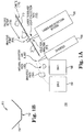
- FIG. 1A illustrates schematically a LIBS measurement system 100 for material sorting according to an embodiment of the invention.
- LIBS measurement 100 includes a concave sampling chute 110, a laser and detection system 120, a diverter 130 and material bins 140 and 150.
- chute 110 as can be seen in FIG. 1B , includes a planar floor 112 bounded by a set of side walls 114.
- a material to be analyzed travels down a concave or substantially V-shaped chute 110 on floor 112 as falling scrap 150 and moves past an analysis hole 113 on floor 112 of chute 110 through which a LIBS (laser induced breakdown system) laser system 120 projects a laser beam 122 through hole 113.
- Laser beam 122 then impinges unto and ablates individual particles of falling scrap 150 that are exposed through hole or orifice or aperture 113 (also known as an analysis point 114).
- An example of a LIBS laser and detection system is taught in US Patent No. 6,795,179 to Kumar , which is incorporated herein by reference in its entirety.
- Diverter device 130 in this example embodiment, is communicatively coupled (wired or wirelessly (for example, RF or Bluetooth)) to laser and detection system 120 such that it is actuated to direct or divert certain scrap samples 152 and 154 to either bin 140 or bin 150.
- scrap sample 152 falls naturally into bin 140 by the force of gravity without the need for diverter 130 and sample 154 is diverted by diverter 130 into bin 150.
- diverter 130 is actuated to divert samples into various bins depending on the instructions received from laser and detection system 120.
- diverter 130 is an air nozzle, an air pump or blower configured to emit shots of air to divert samples 152 or 154.
- diverter 130 includes a member that pushes a sample in the direction of one of the collection bins or collection system,(such as paddles, levers, etc.), or that blocks the forward motion of a sample.
- chute 110 is formed into other configurations, such as a V-shaped channel or a U-shaped channel that allows material to move down the concave-shaped flow chute.
- the flow chute is one of the following configurations: a U-shape with perpendicular sides; U-shaped with flat bottom side; a U-shape with sides angled outward and flat bottom; and a U-shape with sides angled outward and a curved bottom.
- the flow chute is a ramp with a vibration mechanism operatively coupled thereto to promote downward flow of the stream of material.
- the chute includes a vibration mechanism operatively coupled thereto to promote downward flow of the stream of material.
- the flow chute (or sleeve) includes a pipe or cylinder structure with an orifice at the midpoint and bottom surface of the pipe, from which a laser beam can project up and through the orifice.
- the incline or angle of chute 110 is within, but is not limited to, a range of between about 20 degrees to about 70 degrees. At low angles, such as between about 20 to about 30 degrees, a vibrating chute or ramp can also be used. In other embodiments, material speed/chute angle correlations can be determined so as to then correlate to the speed of material moving by the analysis hole on the chute with the laser pulses through the aperture. The speed of the material will also be material-dependent with the laser measurement being virtually instantaneous.
- the laser repetition rate of laser detector system 120 is about 20 Hz, but the laser repetition rate can be matched to the speed of the sample piece presentation at a hole 113.
- the LIBS laser energy must be sufficient to cause a spark at the sample and provide an analysis sufficient to characterize the sample.
- a 200 mJ laser with a long focal length was used and resulted in a depth of focus through the hole that was big enough to accommodate variations of more than 1 inch in the focus of the laser on the sampled material (which could result from piece irregularities in shape).
- a laser light 122 passes through beam shaping optics (not shown) before being focused on the pieces 150 with a focusing lens. In the simplest configuration, a single focusing lens could be used.
- the photodetectors (not shown) used to detect light in the plasma or plume from the sampled material are amplified Si (silicon) photodiodes with a UV enhancement of the type similar to Thorlabs APD120A2.
- any photodetector could be used to capture the emission signal.
- an elemental line filter with about a 5 nm bandpass was used to isolate the emission lines emitted by the sample material.
- other ways of collecting the light and isolating the emission include the combination of an elemental line filter with a photomultiplier tube detector, or the combination of a spectrometer to disperse the light and a detector to detect one or more particular wavelengths.
- a detector/line filter pair was used for each element, but in other implementations a single spectrometer was used to measure many elements simultaneously. Examples of rapid spectral analysis of the optical emissions are taught in U.S. Patent No. 6,753,957 , which is incorporated herein by reference in its entirety.
- the photodetection system is hermetically-sealed and may include input / output windows that are purged as needed.
- FIG. 2 illustrates an example embodiment of a material sorting system using a LIBS measurement system 200 according to an embodiment of the invention.
- LIBS measurement 200 includes a sampling chute 210, a laser and detection system 220, at least one photodetector 224, a bank of diverters 230 and at least one material bin 240 (not shown).
- chute 210 is substantially V-shaped as the sampled material moves down the chute by gravity since the channel is pitched at an angle towards the ground.
- a material to be analyzed travels down chute 210 and moves past an analysis hole 213 (disposed preferably at the maximum point of concavity) of chute 210 through which laser system 220 projects a laser beam 222.
- hole 213 As the laser beam passes through a hole 213 (see 223) it impinges unto the falling scrap that is exposed through hole 213 (also known as an analysis point 214) (not shown) and generates a spectral emission 225 in the form of return light.
- hole 213 is covered with a transparent/translucent member to help keep dust off the main lens of the laser.
- a cleaning or blower assembly can also be included to clean all lenses in the laser system.
- An example of a LIBS laser and detection system is aught in US Patent No. 6,795,179 to Kumar , which is incorporated herein by reference in its entirety.
- the laser of LIBS system 200 fires at the samples from below and through hole or aperture 213, which may vary in size, but in this example the hole is about between 0.25 and 0.375 inches in diameter.
- One of the benefits is that gravity pulls the falling scrap pieces down the chute and keeps them on chute 210. This allows the sample to be a known distance (the floor of the chute) from the laser, and the substantially "V" shape of the chute concentrates most of the material samples in the center of the chute aligned with hole 213.
- the bottom portion 212 of the chute 210 can be narrower or wider, based on the piece size, or the chute can be continuously curved with no flat bottom.
- a bank of diverters 230 in this example embodiment, is communicatively coupled to laser and detection system 220 such that it is actuated to direct or divert certain scrap samples to at least one collection bin or collection system.
- diverters 230 are configured to blow magnesium (Mg) pieces out of a stream of predominantly aluminum (Al) pieces.
- diverters 230 include air pumps or air nozzles or a blower configured to emit shots of air to divert material samples to a certain bin.
- diverters 230 include members that push samples in the direction of a bin or another chute, such as a physical diverter consisting of a wall, a movable paddle or lever, and a controllable trap door at the floor of the flow chute.
- laser 310 emits a laser beam 312 which impinges on a laser line mirror 320 and reflects laser beam 312 towards a focusing lens 330.
- Lens 330 concentrates laser beam 312 into a focused beam 312A that ablates a material sample so as to emit a plasma 340.
- Light 340A from plasma 340 is collimated as it travels back through lens 330 and then passes through another focusing lens 350, converting it into a focused beam 340B that is collected by a detector 360.
- the return light from the sample passes through the same lens that focused the laser, and thereby is efficiently collected and collimated, rather than being collected through a separate lens.
- This configuration can be used in either laser and detection system of systems 100 or system 200 for the collection of light from a plasma formed on a surface of an analyzed material.
- FIG. 4 there is illustrated another example embodiment of a pierced mirror assembly 420 forming part of an optics configuration 400 for a laser and detection system according to the invention.
- laser 410 emits a laser beam 412 which passes through a hole 421 in pierced mirror assembly 420 and impinges on a focusing lens 430.
- Lens 430 concentrates laser beam 412 into a focused beam 412A that ablates a material sample and forms plasma 440.
- Light 440A from plasma 440 is collimated as it travels back through lens 430 and impinges on pierced mirror assembly 420.
- the collimated light from 440A is then reflected by pierced mirror assembly (except for the portion in the center of the collimated light from 440A corresponding to the hole in the pierced mirror 420) to form beam 440B, and then travels through another focusing lens 450 to form focused beam 440C that is collected by a detector 460.
- the pierced mirror assembly inside the device is used to allow the laser to pass through a hole (coming from the back side) of the mirror, while the front side of the mirror reflects the return light out of the laser beam path and onto the detector optics. This arrangement can be used in either laser and detection system 100 or system 200.
- laser parameters include, but are not limited to, active/passive Q-switched configurations; diode and/or lamp pumped configurations; OPO and/or Non-OPO configurations; and Nd:YAG, Er:glass or other viable semiconductor material can be used.
- the laser system can operate at any laser wavelength, for example for Nd:YAG in wavelengths of 1064nm, 532nm, 355nm, 266nm, or 213nm,and with energy of laser pulses in the J (Joule), mJ (millijoule), microJ (microjoule) range, hence any laser energy sufficient to cause a plasma to form at the focal point of the optics.
- any pulse duration of laser e.g. nanosecond, picosecond, or femtosecond
- repetition rate aperiodic to kHz rates or more
Landscapes
- Physics & Mathematics (AREA)
- Health & Medical Sciences (AREA)
- General Physics & Mathematics (AREA)
- Spectroscopy & Molecular Physics (AREA)
- Analytical Chemistry (AREA)
- Nuclear Medicine, Radiotherapy & Molecular Imaging (AREA)
- Life Sciences & Earth Sciences (AREA)
- Chemical & Material Sciences (AREA)
- Plasma & Fusion (AREA)
- Biochemistry (AREA)
- General Health & Medical Sciences (AREA)
- Optics & Photonics (AREA)
- Immunology (AREA)
- Pathology (AREA)
- Engineering & Computer Science (AREA)
- Investigating, Analyzing Materials By Fluorescence Or Luminescence (AREA)
- Investigating Or Analysing Materials By Optical Means (AREA)
Description
- The invention is generally in the field of laser-induced breakdown spectroscopy (LIBS) and more particularly to a method and a system for conducting LIBS analysis of material moving on a conveyor system.
- For various applications, methods are needed for determining the material constitution of a sample. A known method is laser-induced breakdown spectroscopy (LIBS), which involves focusing a laser beam onto a surface of the sample with a high enough power density to transform a small part of the sample material into a state of plasma. Optical emissions from the plasma plume are collected with light collection optics, and the spectral distribution (i.e. intensity as a function of wavelength) of the collected optical emissions is analyzed in a wavelength-sensitive detector such as a spectrometer that produces information in electronic form describing the spectral distribution. Since atomic and molecular constituents of sample materials have characteristic optical emission spectra, the information produced by the spectrometer reveals the constituents of that part of the sample onto which the laser beam was focused or directed.
- The sample may in principle be solid, liquid or gaseous. In the case of a gaseous sample the concept of a "surface" of the sample does not exist, but the laser beam is just focused into the gaseous sample. Drawbacks of known LIBS measurement devices include their bulky structure and limited applicability to field use. In certain applications, LIBS measurement systems are able to characterize various samples in terms of elemental concentrations. In other applications, the type of material, such as a particular alloy composition can be identified with or without the determination of exact elemental concentrations. A primary advantage of the LIBS technology over XRF (x-ray fluorescence) is its ability to determine the elemental concentration of light elements such as Li, B, Be, C, Al, Na and Mg.
- In
U.S. Patent 6,795,179 to Kumar , there is disclosed a metal particle sorting system that includes a conveyor for conveying randomly shaped scrap metal pieces in a random orientation, an image detector for electronically recording the image of a predefined viewing area through which the scrap pieces are conveyed by a traditional flat conveyor system, a position detector for detecting movement of the conveyor belt, a laser system configured to provide a laser beam including a stream of a plurality of laser pulses within a selected time interval, and at least one laser scanner assembly including a positionable beam deflector to direct the laser pulses at a selected piece at any location in a selected target region on the conveyor and a focusing element mounted downstream of the source of the laser pulses from the beam deflector to focus the beam and provide uniform laser power density along a plane. The system further includes a light collector for collecting light from plasma produced on the pieces as they are irradiated by the laser pulses, a light distribution and spectral analyzer system for isolating and measuring at least one selected band from the collected light, a separator to divert pieces to different bins based on discriminator signals, and control logic for continuously acquiring an image of the selected viewing area of the conveyor, processing the image to identify and locate the scrap pieces as they pass through the viewing area, monitoring the laser system to determine when the next laser pulses will be available, selecting a downstream location on the conveyor at which the next available stream of pulses of radiation may be directed at an identified piece, operating the scanner assemblies as required to direct the pulses to the selected target location, analyzing spectral data collected from the plasma, generating a discriminator signal based at least in part upon the spectral data analysis, and selectably activating the separator as a function of the discriminator signal to sort the analyzed pieces. Although apparently effective, this system is equipment- and investment-intensive as several scanner assemblies for generating plasma samples are required as well as control logic for continuously acquiring and processing images of the selected viewing area of the conveyor among other components. - In
U.S. Patent 6,753,957 to Graft et al. , a system and a method is disclosed for mineral sorting and detecting, including remote sensing, and more particularly, for real-time detection and content evaluation of minerals or trace concentrations of elements in materials as they are conveyed on a moving belt. The Graft et al. invention employs a laser-induced breakdown spectroscopy (LIBS) system wherein intensity ratios of the emission lines characteristic of specific elements or minerals enable detection of the same while on a moving belt. Because associated minerals have different chemical compositions, namely, major or minor elements, the relative intensities, defined by their characteristic spectral lines, enable all phases to be consistently identified and assessed within a short time that is consistent with both LIBS and the moving belt system. - In patent document
US 2013/0100444 A1 a system is disclosed for sampling and characterizing by laser-induced breakdown spectroscopy a continuous flow of particulate material, which flows in a vertical chute having a window for optical interrogation. - There is provided herein a method and system for using a LIBS system for conducting rapid material analysis on material traveling along a flow chute, thereby providing spectral measurements quickly and with a reasonably high degree of accuracy for the intended industrial and commercial application.
- In one example embodiment, metal sorting is performed without the need to do laser scanning as in other prior art systems. Instead, each piece of material to be sampled is isolated in a vibrating chute carrying the material thereby avoiding the need for scanning the laser. The laser beam is shot or projected through the bottom of the chute (through a slot or hole) to which the surface of the metal or sample material piece is constrained by gravity, alleviating the need to move the LIBS laser focus in the vertical dimension. By its shape the chute is designed to further constrain the pieces in the side-to-side direction, forcing each piece to move over the hole in the chute. The data that is captured is analyzed by using specific spectral lines to distinguish between material types. The materials are then sorted by an air nozzle or a diverter system according to its composition.
- In various example embodiments of the invention there is provided a method of laser spectroscopy on particles or pieces of material moving along a fixed or stationary material chute that is economical, accurate and faster than prior art systems. Such embodiments contrast with traditional implementations which fire laser light at pieces or particles from above the conveyor belt. In one example embodiment, a LIBS measurement system provided herein includes providing a hole or opening in a substantially V-shaped chute that allows access to the material to be analyzed from the underside of the chute. The laser beam is aimed through the hole and return light (signal) is collected through the hole by a photodetector. The advantages of the aforementioned examples over the traditional sampling method include, but are not limited to: 1) every piece is aligned with the hole in the chute via the V-shape (or concave-shaped) of the chute. Hence every piece can be sampled and little to no segregation occurs. 2) The position of each piece relative to the laser and optical focus is fixed by the chute and force of gravity. Each piece, if sliding on the chute and therefore touching the chute, has a known position. No autofocus and only a moderate depth of field are required. 3) Since the x, y, and z positions of the hole and surface of the piece are known, no motion technology is required, improving reliability and thus the industrial viability of the system. The type of laser and its method of operation are new to the commercial LIBS sorting market.
- The common implementation of measurement from above a conveyor belt has significant problems: 1) If the laser spectroscopy system is fixed in space, items on the belt are not completely sampled. The laser system is only sampling at one point, e.g. the centerline. Vibration and motion on the belt typically make items segregate by size, and so at any fixed point only a sub-sample of particle / piece sizes are sampled. 2) Sampling from above requires either an autofocus or a large depth of field for the optical system. The former introduces complexity and may reduce sampling speed; the latter introduces additional uncertainty over a more focused optical system. 3) Implementations from above a belt that have tried to track every piece (for example, the LIBS system from Fraunhofer ILT (Aachen, Germany) for sorting metal scrap) have used 3D cameras and moving mirrors to aim a laser system at moving pieces. This complexity is enormous and impacts industrial reliability and viability of the system.
- The novel features of the various embodiments of the invention itself, both as to its construction and its method of operation, together with additional advantages thereof, will be best understood from the following description of specific embodiments when read in connection with the accompanying drawings.
-
-
FIGS. 1A-1B illustrate schematically an example embodiment of a LIBS measurement system and a side view of a flow chute according to the teachings herein; -
FIG. 2 illustrates an example embodiment of a LIBS measurement system according to the teachings herein; -
FIG. 3 illustrates an example embodiment of the laser and detection system ofsystems -
FIG. 4 illustrates another example embodiment of a pierced mirror assembly that can be used in eithersystems - Following are more detailed descriptions of various related concepts related to, and embodiments of, methods and apparatus according to the present disclosure. It should be appreciated that various aspects of the subject matter introduced above and discussed in greater detail below may be implemented in any of numerous ways, as the subject matter is not limited to any particular manner of implementation. Examples of specific implementations and applications are provided primarily for illustrative purposes.
- In one example embodiment of the invention, there is provided a bulk sampling and laser-targeting system to provide for material identification of a bulk stream of material including a flow chute having a feeder end and an output end, the output end adapted to extend at an angle away from the feeder end such that the flow chute is at an incline and the bulk stream of material flows along the flow chute gravitationally, the flow chute having a substantially concave-shaped configuration including an aperture disposed at a point of maximum concavity or trough of the flow chute that is a distance from the feeder end such that the bulk stream of material can form into an orderly flow down the chute. The system also includes a LIBS laser system disposed adjacent the aperture and configured to direct a pulsed laser beam through the aperture and into a material flowing through the flow chute, the aperture having a size sufficient to permit the laser beam to pass through to individual particles of the flowing material and to permit radiation from the individual particles to transmit back through the aperture. In addition, a radiation detection device is included that is disposed adjacent the aperture and adapted to collect the radiation emitted from the individual particles of material, wherein the radiation detection device is communicatively coupled to the LIBS laser system that includes a spectrometer and a controller, the spectrometer configured to identify a composition of the individual particles flowing in the chute. Finally, in a related embodiment the system includes at least one particle diverter device disposed adjacent the output end of the chute and adapted to divert the individual particle towards a collection system, wherein the at least one particle diverter device is communicatively coupled to the controller and is adapted to actuate upon receipt of a signal from the controller.
- In another embodiment, there are provided a bulk sampling and laser-targeting system to provide for material identification of a bulk stream of material that includes a flow chute having a feeder end and an output end, the output end adapted to extend at an angle away from the feeder end such that the flow chute is at an incline and the bulk stream of material flows along the flow chute gravitationally, the flow chute having a substantially v-shaped configuration including an aperture disposed near the point of the maximum concavity of the V of the flow chute that is a distance from the feeder end such that the bulk stream of material can form into an orderly flow down the chute. Further, a LIBS laser system is included that is disposed adjacent the aperture and configured to direct a pulsed laser beam through the aperture and into a material flowing through the flow chute, the aperture having a size sufficient to permit the laser beam to pass through to individual particles of the flowing material and to permit radiation from the individual particles to transmit back through the aperture. The system further includes a radiation detection device that is disposed adjacent the aperture and adapted to collect the radiation emitted from the individual particles of material, wherein the radiation detection device is communicatively coupled to the LIBS laser system that includes a spectrometer and a controller, the spectrometer configured to identify a composition of the individual particles flowing in the chute from radiation received through a pierced mirror assembly configured to allow the laser beam to pass from a back side of the mirror assembly and through a hole of the mirror, while a front side of the mirror assembly is configured to substantially reflect the return light out of the laser beam path and onto a radiation detector optics of the radiation detection device. The system finally includes, in a related embodiment, at least one particle diverter device disposed adjacent the output end of the chute and adapted to divert the individual particle towards a collection system, wherein the at least one particle diverter device is communicatively coupled to the controller and is adapted to actuate upon receipt of a signal from the controller.
- In yet another embodiment, a method is provided of bulk sampling and laser-targeting of a bulk stream of material that includes the steps of providing an angled flow chute having a feeder end and an output end adapted to extend at an angle away from the feeder end such that the flow chute is at an incline and the bulk stream of material flows along the flow chute gravitationally, the flow chute having a substantially v-shaped configuration including an aperture or orifice disposed in the center of the trough of the flow chute that is some distance from the feeder end such that the bulk stream of material can form into an orderly flow down the chute. In addition, the method includes the step of directing a laser beam, from a LIBS laser system disposed adjacent the aperture, through the aperture and ablating a material flowing through the flow chute, the aperture having a size sufficient to permit the laser beam to pass through to individual particles of the flowing material and to permit radiation from the ablated individual particles to transmit back through the aperture; collecting radiation emitting through the aperture from the individual ablated material particles and directing them to a spectrometer in the LIBS laser system having a controller therein, the spectrometer configured to identify a composition of the individual particles flowing in the chute. The method further includes, in a related embodiment, providing at least one particle diverter device disposed adjacent the output end of the chute and adapted to divert the individual particle towards a collection system, wherein the at least one particle diverter device is communicatively coupled to the controller and is adapted to actuate upon receipt of a signal from the controller.
- Referring now to
FIGS. 1A and 1B, FIG. 1A illustrates schematically aLIBS measurement system 100 for material sorting according to an embodiment of the invention. In this example embodiment,LIBS measurement 100 includes aconcave sampling chute 110, a laser anddetection system 120, adiverter 130 andmaterial bins chute 110, as can be seen inFIG. 1B , includes aplanar floor 112 bounded by a set ofside walls 114. In this example embodiment, a material to be analyzed travels down a concave or substantially V-shapedchute 110 onfloor 112 as fallingscrap 150 and moves past ananalysis hole 113 onfloor 112 ofchute 110 through which a LIBS (laser induced breakdown system)laser system 120 projects a laser beam 122 throughhole 113. Laser beam 122 then impinges unto and ablates individual particles of fallingscrap 150 that are exposed through hole or orifice or aperture 113 (also known as an analysis point 114). An example of a LIBS laser and detection system is taught inUS Patent No. 6,795,179 to Kumar , which is incorporated herein by reference in its entirety. -
Diverter device 130, in this example embodiment, is communicatively coupled (wired or wirelessly (for example, RF or Bluetooth)) to laser anddetection system 120 such that it is actuated to direct or divertcertain scrap samples bin 140 orbin 150. In this example embodiment,scrap sample 152 falls naturally intobin 140 by the force of gravity without the need fordiverter 130 andsample 154 is diverted bydiverter 130 intobin 150. In a related embodiment, depending on the location of the bins and the number of bins,diverter 130 is actuated to divert samples into various bins depending on the instructions received from laser anddetection system 120. In this example embodiment,diverter 130 is an air nozzle, an air pump or blower configured to emit shots of air to divertsamples diverter 130 includes a member that pushes a sample in the direction of one of the collection bins or collection system,(such as paddles, levers, etc.), or that blocks the forward motion of a sample. - In related embodiments,
chute 110 is formed into other configurations, such as a V-shaped channel or a U-shaped channel that allows material to move down the concave-shaped flow chute. In other embodiments, the flow chute is one of the following configurations: a U-shape with perpendicular sides; U-shaped with flat bottom side; a U-shape with sides angled outward and flat bottom; and a U-shape with sides angled outward and a curved bottom. In yet another embodiment, the flow chute is a ramp with a vibration mechanism operatively coupled thereto to promote downward flow of the stream of material. In another embodiment, the chute includes a vibration mechanism operatively coupled thereto to promote downward flow of the stream of material. In yet another embodiment, the flow chute (or sleeve) includes a pipe or cylinder structure with an orifice at the midpoint and bottom surface of the pipe, from which a laser beam can project up and through the orifice. - In various embodiments, the incline or angle of
chute 110 is within, but is not limited to, a range of between about 20 degrees to about 70 degrees. At low angles, such as between about 20 to about 30 degrees, a vibrating chute or ramp can also be used. In other embodiments, material speed/chute angle correlations can be determined so as to then correlate to the speed of material moving by the analysis hole on the chute with the laser pulses through the aperture. The speed of the material will also be material-dependent with the laser measurement being virtually instantaneous. - Normally, there are irregularities in the shape of the material targets, but if these are within range of the laser focus, this eliminates the need for autofocus. In a related embodiment, autofocus is used in
system 100 when the irregularly shaped targets are out of range of laser focus. One of the advantages ofLIBS measurement system 100 is that the user does not need to track the sample pieces on a wide moving belt, as in prior art implementations. - In one example embodiment, the laser repetition rate of
laser detector system 120 is about 20 Hz, but the laser repetition rate can be matched to the speed of the sample piece presentation at ahole 113. The LIBS laser energy must be sufficient to cause a spark at the sample and provide an analysis sufficient to characterize the sample. In this example embodiment, a 200 mJ laser with a long focal length was used and resulted in a depth of focus through the hole that was big enough to accommodate variations of more than 1 inch in the focus of the laser on the sampled material (which could result from piece irregularities in shape). In this example embodiment, a laser light 122 passes through beam shaping optics (not shown) before being focused on thepieces 150 with a focusing lens. In the simplest configuration, a single focusing lens could be used. - In this example embodiment, the photodetectors (not shown) used to detect light in the plasma or plume from the sampled material are amplified Si (silicon) photodiodes with a UV enhancement of the type similar to Thorlabs APD120A2. However, any photodetector could be used to capture the emission signal. In this example embodiment, an elemental line filter with about a 5 nm bandpass was used to isolate the emission lines emitted by the sample material. In related embodiments, other ways of collecting the light and isolating the emission include the combination of an elemental line filter with a photomultiplier tube detector, or the combination of a spectrometer to disperse the light and a detector to detect one or more particular wavelengths. In one example embodiment, a detector/line filter pair was used for each element, but in other implementations a single spectrometer was used to measure many elements simultaneously. Examples of rapid spectral analysis of the optical emissions are taught in
U.S. Patent No. 6,753,957 , which is incorporated herein by reference in its entirety. Generally, the photodetection system is hermetically-sealed and may include input / output windows that are purged as needed. -
FIG. 2 illustrates an example embodiment of a material sorting system using aLIBS measurement system 200 according to an embodiment of the invention. In this example embodiment,LIBS measurement 200 includes asampling chute 210, a laser anddetection system 220, at least onephotodetector 224, a bank ofdiverters 230 and at least one material bin 240 (not shown). In this example embodiment,chute 210 is substantially V-shaped as the sampled material moves down the chute by gravity since the channel is pitched at an angle towards the ground. In this example embodiment, a material to be analyzed travels downchute 210 and moves past an analysis hole 213 (disposed preferably at the maximum point of concavity) ofchute 210 through whichlaser system 220 projects a laser beam 222. As the laser beam passes through a hole 213 (see 223) it impinges unto the falling scrap that is exposed through hole 213 (also known as an analysis point 214) (not shown) and generates a spectral emission 225 in the form of return light. In a related embodiment,hole 213 is covered with a transparent/translucent member to help keep dust off the main lens of the laser. A cleaning or blower assembly can also be included to clean all lenses in the laser system. An example of a LIBS laser and detection system is aught inUS Patent No. 6,795,179 to Kumar , which is incorporated herein by reference in its entirety. - In this example embodiment, the laser of
LIBS system 200 fires at the samples from below and through hole oraperture 213, which may vary in size, but in this example the hole is about between 0.25 and 0.375 inches in diameter. One of the benefits is that gravity pulls the falling scrap pieces down the chute and keeps them onchute 210. This allows the sample to be a known distance (the floor of the chute) from the laser, and the substantially "V" shape of the chute concentrates most of the material samples in the center of the chute aligned withhole 213. The bottom portion 212 of thechute 210 can be narrower or wider, based on the piece size, or the chute can be continuously curved with no flat bottom. A bank ofdiverters 230, in this example embodiment, is communicatively coupled to laser anddetection system 220 such that it is actuated to direct or divert certain scrap samples to at least one collection bin or collection system. In this example embodiment,diverters 230 are configured to blow magnesium (Mg) pieces out of a stream of predominantly aluminum (Al) pieces. In this example embodiment,diverters 230 include air pumps or air nozzles or a blower configured to emit shots of air to divert material samples to a certain bin. In a related embodiment,diverters 230 include members that push samples in the direction of a bin or another chute, such as a physical diverter consisting of a wall, a movable paddle or lever, and a controllable trap door at the floor of the flow chute. - Referring now to
FIG. 3 , there is illustrated an example embodiment of an optics configuration of a laser anddetection system 300 according to the invention. Specifically, laser 310 emits alaser beam 312 which impinges on a laser line mirror 320 and reflectslaser beam 312 towards a focusinglens 330.Lens 330 concentrateslaser beam 312 into afocused beam 312A that ablates a material sample so as to emit aplasma 340. Light 340A fromplasma 340 is collimated as it travels back throughlens 330 and then passes through another focusing lens 350, converting it into afocused beam 340B that is collected by adetector 360. In this advantageous example, the return light from the sample passes through the same lens that focused the laser, and thereby is efficiently collected and collimated, rather than being collected through a separate lens. This configuration can be used in either laser and detection system ofsystems 100 orsystem 200 for the collection of light from a plasma formed on a surface of an analyzed material. - Referring now to
FIG. 4 , there is illustrated another example embodiment of a pierced mirror assembly 420 forming part of anoptics configuration 400 for a laser and detection system according to the invention. Specifically,laser 410 emits alaser beam 412 which passes through a hole 421 in pierced mirror assembly 420 and impinges on a focusing lens 430. Lens 430 concentrateslaser beam 412 into afocused beam 412A that ablates a material sample and formsplasma 440. Light 440A fromplasma 440 is collimated as it travels back through lens 430 and impinges on pierced mirror assembly 420. The collimated light from 440A is then reflected by pierced mirror assembly (except for the portion in the center of the collimated light from 440A corresponding to the hole in the pierced mirror 420) toform beam 440B, and then travels through another focusinglens 450 to form focused beam 440C that is collected by adetector 460. In this advantageous example optics configuration, the pierced mirror assembly inside the device is used to allow the laser to pass through a hole (coming from the back side) of the mirror, while the front side of the mirror reflects the return light out of the laser beam path and onto the detector optics. This arrangement can be used in either laser anddetection system 100 orsystem 200. - In various embodiments described herein, laser parameters include, but are not limited to, active/passive Q-switched configurations; diode and/or lamp pumped configurations; OPO and/or Non-OPO configurations; and Nd:YAG, Er:glass or other viable semiconductor material can be used. The laser system can operate at any laser wavelength, for example for Nd:YAG in wavelengths of 1064nm, 532nm, 355nm, 266nm, or 213nm,and with energy of laser pulses in the J (Joule), mJ (millijoule), microJ (microjoule) range, hence any laser energy sufficient to cause a plasma to form at the focal point of the optics. Similarly, any pulse duration of laser (e.g. nanosecond, picosecond, or femtosecond) and repetition rate (aperiodic to kHz rates or more) may be used, if sufficient to cause a plasma to form on the material to be analyzed.
- Primary applications for the LIBS systems taught herein include but are not limited to: aluminum scrap sorters and secondary aluminum smelters which accept aluminum scrap, to value and verify the scrap as it comes in. Other applications include analysis of other non-ferrous metals, ferrous metals, refractory materials, and soils.
- The following patents relate to such LIBS devices:
U.S. Pat. Nos. 6,753,957 ;6,795,179 ;7,763,820 ; and7,821,634 andU.S. Patent Publication No. 2013/0079918 . - Having thus described several illustrative embodiments, it is to be appreciated that various alterations, modifications, and improvements will readily occur to those skilled in the art. The scope of the invention is defined in the attached claims. While some examples presented herein involve specific combinations of functions or structural elements, it should be understood that those functions and elements may be combined in other ways according to the present invention to accomplish the same or different objectives. In particular, acts, elements, and features discussed in connection with one embodiment are not intended to be excluded from similar or other roles in other embodiments. Accordingly, the foregoing description and attached drawings are by way of example only, and are not intended to be limiting.
Claims (11)
- A bulk sampling and laser-targeting system to provide for material identification of a bulk stream of material particles using laser-induced breakdown spectroscopy, LIBS, the system comprising:a flow chute (110; 210) having a feeder end and an output end, configured to cause a bulk stream of material particles to flow along the flow chute (110; 210) gravitationally, whilst being supported against gravity by the chute, the flow chute (110; 210) including an aperture (113; 213);a LIBS laser system (310; 410) disposed adjacent the aperture (113; 213) and configured to direct a pulsed laser beam (412, 412A) through the aperture (113; 213) and into a material flowing through the flow chute (110; 210), the aperture (113; 213) having a size sufficient to permit the laser beam (412, 412A) to pass through to individual particles of the flowing material and to permit radiation from the individual particles to transmit back through the aperture (113; 213); anda radiation detection device (360; 460) disposed adjacent the aperture (113; 213) and adapted to collect the radiation emitted from the individual particles of material, wherein the radiation detection device (360; 460) is communicatively coupled to the LIBS laser system (310; 410) that includes a spectrometer and a controller, the spectrometer configured to identify a composition of the individual particles flowing in the flow chute,characterized in that the output end is angled down from the feeder end such that the flow chute (110; 210) is at an incline,the flow chute (110; 210) has a substantially concave-shaped configuration in cross-section in a plane perpendicular to the direction of flow of the material, such that the material particles are constrained in a direction transverse to the flow direction and pass over the aperture,the aperture (113; 213) is disposed at a point of maximum concavity of the flow chute (110; 210) that is distal to the feeder end, wherein the aperture (113; 213) is formed through the underside of the flow chute (110; 210).
- The system of claim 1 further comprising:
at least one particle diverter device disposed adjacent the output end of the flow chute and adapted to divert the individual particle towards a collection system, wherein the at least one particle diverter device is communicatively coupled to the controller and is adapted to actuate upon receipt of a signal from the controller. - The system of claim 2 wherein the at least one particle diverter includes a diverter device adapted to emit a burst of pressurized air when actuated at one or more individual particles of material so as to divert the individual particle towards the collection system.
- The system of any one of claims 1 to 3, wherein the radiation detection device (460) includes a pierced mirror assembly (420) configured to allow the laser beam (412, 412A) to pass from a back side of the mirror assembly (420) and through a hole (421) of the mirror, while a front side of the mirror assembly (420) is configured to substantially reflect the return light out of the laser beam path and onto a radiation detector optics.
- The system of any one of claims 1 to 4, further comprising a cleaning assembly configured to maintain optics of the LIBS and the radiation detection system substantially dust-free.
- The system of any one of claims 1 to 5, further comprising a transparent or translucent member disposed over the aperture (113; 213).
- The system of any one of claims 1 to 6, wherein a repetition rate of the LIBS laser beam is a function of the speed of material flow along the flow chute (110; 210) and wherein the speed of material flow along the flow chute (110; 210) is a function of the angle of the flow chute (110; 210).
- The system of any one of claims 1 to 7, wherein the concave-shaped flow chute (110; 210) has a substantially V-shaped configuration.
- The system of any one of claims 1 to 7, wherein the concave-shape of the flow chute (110; 210) is selected from the group consisting of a V-shape; a U-shape with perpendicular sides; a U-shape with flat bottom side; a U-shape with sides angled outward and flat bottom; and a U-shape with sides angled outward and a curved bottom.
- The system of any one of claims 1 to 9, wherein the flow chute (110; 210) comprises a ramp with a vibration mechanism operatively coupled thereto to promote downward flow of the stream of material.
- The system of any one of claims 1 to 7, wherein the flow chute (110; 210) has a substantially V-shaped configuration;
and wherein the spectrometer is configured to identify a composition of the individual particles flowing in the flow chute from radiation received through a pierced mirror assembly (420) configured to allow the laser beam (412, 412A) to pass from a back side of the mirror assembly (420) and through a hole (421) of the mirror, while a front side of the mirror assembly (420) is configured to substantially reflect the return light out of the laser beam path and onto a radiation detector optics of the radiation detection device (460).
Applications Claiming Priority (2)
| Application Number | Priority Date | Filing Date | Title |
|---|---|---|---|
| US201462015756P | 2014-06-23 | 2014-06-23 | |
| PCT/US2015/036617 WO2015200111A1 (en) | 2014-06-23 | 2015-06-19 | Rapid material analysis using libs spectroscopy |
Publications (2)
| Publication Number | Publication Date |
|---|---|
| EP3158324A1 EP3158324A1 (en) | 2017-04-26 |
| EP3158324B1 true EP3158324B1 (en) | 2019-08-28 |
Family
ID=53540844
Family Applications (1)
| Application Number | Title | Priority Date | Filing Date |
|---|---|---|---|
| EP15736090.0A Active EP3158324B1 (en) | 2014-06-23 | 2015-06-19 | Rapid material analysis using libs spectroscopy |
Country Status (5)
| Country | Link |
|---|---|
| US (1) | US10088425B2 (en) |
| EP (1) | EP3158324B1 (en) |
| CN (1) | CN107107122B (en) |
| BR (1) | BR112016030481A2 (en) |
| WO (1) | WO2015200111A1 (en) |
Cited By (1)
| Publication number | Priority date | Publication date | Assignee | Title |
|---|---|---|---|---|
| EP3967413A1 (en) | 2020-09-10 | 2022-03-16 | Binder + Co AG | Sorting apparatus with libs laser device |
Families Citing this family (27)
| Publication number | Priority date | Publication date | Assignee | Title |
|---|---|---|---|---|
| US12208421B2 (en) | 2015-07-16 | 2025-01-28 | Sortera Technologies, Inc. | Metal separation in a scrap yard |
| US11278937B2 (en) | 2015-07-16 | 2022-03-22 | Sortera Alloys, Inc. | Multiple stage sorting |
| US12280403B2 (en) | 2015-07-16 | 2025-04-22 | Sortera Technologies, Inc. | Sorting based on chemical composition |
| US12551931B2 (en) | 2015-07-16 | 2026-02-17 | Sortera Technologies, Inc. | Classifying of materials with contaminants |
| US11964304B2 (en) | 2015-07-16 | 2024-04-23 | Sortera Technologies, Inc. | Sorting between metal alloys |
| US12508628B2 (en) | 2015-07-16 | 2025-12-30 | Sortera Technologies, Inc. | Sorting between metal alloys |
| CN107305187A (en) * | 2016-04-18 | 2017-10-31 | 核工业北京地质研究院 | A kind of Minerals identification method based on LIBS and linear discriminant |
| CN107782715B (en) * | 2016-08-24 | 2020-11-06 | 中国科学院光电研究院 | Method for detecting the composition of steel samples using multi-pulse laser-induced plasma spectrometry equipment |
| US10478861B2 (en) * | 2016-11-28 | 2019-11-19 | Hydro Aluminium Rolled Products Gmbh | System for analyzing and sorting material |
| EP3343205A1 (en) * | 2016-12-30 | 2018-07-04 | Lenz Instruments S.L. | A system for analysing the chemical composition of a target material and corresponding process |
| WO2018143355A1 (en) * | 2017-02-01 | 2018-08-09 | イマジニアリング株式会社 | Analysis device |
| EP3586984A4 (en) | 2017-02-27 | 2020-11-18 | Eric Van Looy | METHOD AND DEVICE FOR THE SELECTION AND ANALYSIS OF BULK MATERIAL |
| CN107008667A (en) * | 2017-04-28 | 2017-08-04 | 安徽捷迅光电技术有限公司 | A kind of discharging structure on color selector |
| CN108212822B (en) * | 2017-12-08 | 2020-07-14 | 江苏科技大学 | Quick male and female silkworm chrysalis sorting device and method |
| CN110548697A (en) * | 2018-05-30 | 2019-12-10 | 中国科学院沈阳自动化研究所 | intelligent waste metal sorting system and method based on optical fiber laser |
| CN112236661A (en) | 2018-06-07 | 2021-01-15 | 传感器公司 | Particle concentration analysis system and method |
| FR3087049A1 (en) * | 2018-10-08 | 2020-04-10 | Commissariat A L'energie Atomique Et Aux Energies Alternatives | METHOD FOR DETERMINING THE TECHNOLOGY OF A PHOTOVOLTAIC CELL, SORTING METHOD, RECYCLING METHOD AND ASSOCIATED DEVICE |
| JP7225786B2 (en) * | 2018-12-21 | 2023-02-21 | 株式会社Ihi | Powder flow controller for spectroscopy |
| EP4082679B1 (en) * | 2019-12-24 | 2025-01-22 | Satake Corporation | Optical sorting device |
| JP7375527B2 (en) * | 2019-12-24 | 2023-11-08 | 株式会社サタケ | Optical sorting device |
| JP7375528B2 (en) * | 2019-12-24 | 2023-11-08 | 株式会社サタケ | Optical sorting device |
| CN113740313B (en) * | 2021-02-04 | 2024-08-02 | 聚光科技(杭州)股份有限公司 | LIBS technology-based online detection device and method |
| US12578276B2 (en) * | 2021-04-02 | 2026-03-17 | Impossible Sensing LLC | Method and system for mapping elemental composition in dynamic and heterogenous material |
| HUE073510T2 (en) * | 2022-05-20 | 2026-01-28 | Hydro Aluminium Recycling Deutschland Gmbh | System for analyzing and sorting an elementary material |
| ES2991635T3 (en) * | 2022-05-30 | 2024-12-04 | Binder Co Ag | Sorting device |
| NO349343B1 (en) * | 2024-05-15 | 2025-12-15 | Eco Mat As | Material Sorting System and Process |
| US12303942B1 (en) | 2024-09-06 | 2025-05-20 | Trinity Metals, LLC | System and method for mixed material magnesium sorting |
Family Cites Families (18)
| Publication number | Priority date | Publication date | Assignee | Title |
|---|---|---|---|---|
| US4096949A (en) * | 1976-06-01 | 1978-06-27 | Geosource Inc. | Apparatus for performing a three-way sort |
| DE3790473C2 (en) * | 1986-08-20 | 1995-04-27 | De Beers Cons Mines Ltd | Separating method for diamonds |
| DE4426475C2 (en) * | 1993-07-27 | 1996-01-11 | Hohla Kristian | Device for laser-induced plasma spectroscopy for the material analysis of parts guided on a transport unit |
| US6545240B2 (en) * | 1996-02-16 | 2003-04-08 | Huron Valley Steel Corporation | Metal scrap sorting system |
| US5986230A (en) * | 1996-09-13 | 1999-11-16 | Uncle Ben's, Inc. | Method and apparatus for sorting product |
| US6753957B1 (en) | 2001-08-17 | 2004-06-22 | Florida Institute Of Phosphate Research | Mineral detection and content evaluation method |
| DE10149505A1 (en) | 2001-10-02 | 2003-04-10 | Krieg Gunther | Method and device for selecting plastics and other materials with regard to color and composition |
| US7763820B1 (en) * | 2003-01-27 | 2010-07-27 | Spectramet, Llc | Sorting pieces of material based on photonic emissions resulting from multiple sources of stimuli |
| CA2683515A1 (en) | 2007-04-20 | 2008-12-31 | Thermo Niton Analyzers Llc | Laser-triggered plasma apparatus for atomic emission spectroscopy |
| US20120019819A1 (en) * | 2009-01-21 | 2012-01-26 | Rare Light, Inc. | Raman spectroscopy using multiple discrete light sources |
| EA201390408A1 (en) | 2010-10-01 | 2013-10-30 | Текнолоджикал Ресорсиз Пти. Лимитед | LASER-SPARK EMISSION SPECTROSCOPIC ANALYZER |
| RU2601934C2 (en) * | 2011-08-10 | 2016-11-10 | Проассорт Гмбх | Metal scrap sorting |
| US8855809B2 (en) | 2011-09-01 | 2014-10-07 | Spectramet, Llc | Material sorting technology |
| US8902422B2 (en) * | 2011-10-21 | 2014-12-02 | Chesner Engineering, Pc | Bulk material sampling and laser targeting system |
| BR112014024083B1 (en) | 2012-03-27 | 2021-10-26 | Satake Corporation | OPTICAL GRANULE TYPE CLASSIFICATION MACHINE |
| CN202984137U (en) * | 2012-12-27 | 2013-06-12 | 遵义师范学院 | Device for sorting grains polluted by aflatoxin B1 |
| CN103816976A (en) * | 2014-02-27 | 2014-05-28 | 王宏 | Laser-induced breakdown spectroscopic (LIBS) intelligent sorting method and apparatus for ore |
| US10478861B2 (en) * | 2016-11-28 | 2019-11-19 | Hydro Aluminium Rolled Products Gmbh | System for analyzing and sorting material |
-
2015
- 2015-06-19 CN CN201580045277.9A patent/CN107107122B/en not_active Expired - Fee Related
- 2015-06-19 US US15/321,143 patent/US10088425B2/en active Active
- 2015-06-19 WO PCT/US2015/036617 patent/WO2015200111A1/en not_active Ceased
- 2015-06-19 EP EP15736090.0A patent/EP3158324B1/en active Active
- 2015-06-19 BR BR112016030481A patent/BR112016030481A2/en not_active IP Right Cessation
Non-Patent Citations (1)
| Title |
|---|
| None * |
Cited By (2)
| Publication number | Priority date | Publication date | Assignee | Title |
|---|---|---|---|---|
| EP3967413A1 (en) | 2020-09-10 | 2022-03-16 | Binder + Co AG | Sorting apparatus with libs laser device |
| US11541426B2 (en) | 2020-09-10 | 2023-01-03 | Binder + Co Ag | Sorting apparatus with a LIBS laser device |
Also Published As
| Publication number | Publication date |
|---|---|
| CN107107122A (en) | 2017-08-29 |
| BR112016030481A2 (en) | 2021-01-12 |
| EP3158324A1 (en) | 2017-04-26 |
| US20170205354A1 (en) | 2017-07-20 |
| WO2015200111A1 (en) | 2015-12-30 |
| CN107107122B (en) | 2019-07-23 |
| US10088425B2 (en) | 2018-10-02 |
Similar Documents
| Publication | Publication Date | Title |
|---|---|---|
| EP3158324B1 (en) | Rapid material analysis using libs spectroscopy | |
| EP3586984A1 (en) | Method and apparatus for selecting and analysing bulk material | |
| US6795179B2 (en) | Metal scrap sorting system | |
| CN105829843B (en) | High-speed spectral sensor components and systems | |
| US6700660B2 (en) | Method and apparatus for in-process liquid analysis by laser induced plasma spectroscopy | |
| AU2012265822B2 (en) | Method and apparatus for quantitative analysis of samples by laser induced plasma (LIP) | |
| US8902422B2 (en) | Bulk material sampling and laser targeting system | |
| US5628410A (en) | Classifying or sorting | |
| US12459006B2 (en) | System for the online sorting of ore samples based on a mineralogy analysis | |
| AU2012265822A1 (en) | Method and apparatus for quantitative analysis of samples by laser induced plasma (LIP) | |
| FI3967413T3 (en) | Sorting apparatus with libs laser device and method | |
| AU2006261627B2 (en) | In-stream spectroscopic elemental analysis of particles being conducted within a gaseous stream | |
| EP1416265B1 (en) | Scanning system for use in a metal scrap sorting system | |
| CN110018154A (en) | An aerosol detection device and method based on laser-induced breakdown spectroscopy | |
| GB2280956A (en) | Detecting diamonds in a plurality of objects | |
| AU697587B2 (en) | Classification of particles according to raman response | |
| Rostedt et al. | Optical chamber design for aerosol particle fluorescent measurement | |
| NO330164B1 (en) | Scanning system for use in metal waste sorting system | |
| FR2976671A1 (en) | Method for detecting and proportioning e.g. toxic element, in e.g. solid material sample, in medium, involves calculating element concentration in sample by measuring relative variations of spectral radiant intensity in absorption spectrum |
Legal Events
| Date | Code | Title | Description |
|---|---|---|---|
| STAA | Information on the status of an ep patent application or granted ep patent |
Free format text: STATUS: THE INTERNATIONAL PUBLICATION HAS BEEN MADE |
|
| PUAI | Public reference made under article 153(3) epc to a published international application that has entered the european phase |
Free format text: ORIGINAL CODE: 0009012 |
|
| STAA | Information on the status of an ep patent application or granted ep patent |
Free format text: STATUS: REQUEST FOR EXAMINATION WAS MADE |
|
| 17P | Request for examination filed |
Effective date: 20170104 |
|
| AK | Designated contracting states |
Kind code of ref document: A1 Designated state(s): AL AT BE BG CH CY CZ DE DK EE ES FI FR GB GR HR HU IE IS IT LI LT LU LV MC MK MT NL NO PL PT RO RS SE SI SK SM TR |
|
| AX | Request for extension of the european patent |
Extension state: BA ME |
|
| DAV | Request for validation of the european patent (deleted) | ||
| DAX | Request for extension of the european patent (deleted) | ||
| GRAP | Despatch of communication of intention to grant a patent |
Free format text: ORIGINAL CODE: EPIDOSNIGR1 |
|
| STAA | Information on the status of an ep patent application or granted ep patent |
Free format text: STATUS: GRANT OF PATENT IS INTENDED |
|
| INTG | Intention to grant announced |
Effective date: 20190306 |
|
| GRAS | Grant fee paid |
Free format text: ORIGINAL CODE: EPIDOSNIGR3 |
|
| GRAA | (expected) grant |
Free format text: ORIGINAL CODE: 0009210 |
|
| STAA | Information on the status of an ep patent application or granted ep patent |
Free format text: STATUS: THE PATENT HAS BEEN GRANTED |
|
| RIN1 | Information on inventor provided before grant (corrected) |
Inventor name: NICCUM, DARRICK L. Inventor name: BUCKLEY, STEVEN G. Inventor name: COMTOIS, RICKY ROLAND |
|
| AK | Designated contracting states |
Kind code of ref document: B1 Designated state(s): AL AT BE BG CH CY CZ DE DK EE ES FI FR GB GR HR HU IE IS IT LI LT LU LV MC MK MT NL NO PL PT RO RS SE SI SK SM TR |
|
| RAP1 | Party data changed (applicant data changed or rights of an application transferred) |
Owner name: TSI INCORPORATED |
|
| REG | Reference to a national code |
Ref country code: GB Ref legal event code: FG4D |
|
| REG | Reference to a national code |
Ref country code: CH Ref legal event code: EP |
|
| REG | Reference to a national code |
Ref country code: AT Ref legal event code: REF Ref document number: 1173020 Country of ref document: AT Kind code of ref document: T Effective date: 20190915 |
|
| REG | Reference to a national code |
Ref country code: IE Ref legal event code: FG4D |
|
| REG | Reference to a national code |
Ref country code: DE Ref legal event code: R096 Ref document number: 602015036707 Country of ref document: DE |
|
| REG | Reference to a national code |
Ref country code: NL Ref legal event code: MP Effective date: 20190828 |
|
| REG | Reference to a national code |
Ref country code: LT Ref legal event code: MG4D |
|
| PG25 | Lapsed in a contracting state [announced via postgrant information from national office to epo] |
Ref country code: NO Free format text: LAPSE BECAUSE OF FAILURE TO SUBMIT A TRANSLATION OF THE DESCRIPTION OR TO PAY THE FEE WITHIN THE PRESCRIBED TIME-LIMIT Effective date: 20191128 Ref country code: SE Free format text: LAPSE BECAUSE OF FAILURE TO SUBMIT A TRANSLATION OF THE DESCRIPTION OR TO PAY THE FEE WITHIN THE PRESCRIBED TIME-LIMIT Effective date: 20190828 Ref country code: HR Free format text: LAPSE BECAUSE OF FAILURE TO SUBMIT A TRANSLATION OF THE DESCRIPTION OR TO PAY THE FEE WITHIN THE PRESCRIBED TIME-LIMIT Effective date: 20190828 Ref country code: PT Free format text: LAPSE BECAUSE OF FAILURE TO SUBMIT A TRANSLATION OF THE DESCRIPTION OR TO PAY THE FEE WITHIN THE PRESCRIBED TIME-LIMIT Effective date: 20191230 Ref country code: FI Free format text: LAPSE BECAUSE OF FAILURE TO SUBMIT A TRANSLATION OF THE DESCRIPTION OR TO PAY THE FEE WITHIN THE PRESCRIBED TIME-LIMIT Effective date: 20190828 Ref country code: LT Free format text: LAPSE BECAUSE OF FAILURE TO SUBMIT A TRANSLATION OF THE DESCRIPTION OR TO PAY THE FEE WITHIN THE PRESCRIBED TIME-LIMIT Effective date: 20190828 Ref country code: NL Free format text: LAPSE BECAUSE OF FAILURE TO SUBMIT A TRANSLATION OF THE DESCRIPTION OR TO PAY THE FEE WITHIN THE PRESCRIBED TIME-LIMIT Effective date: 20190828 Ref country code: BG Free format text: LAPSE BECAUSE OF FAILURE TO SUBMIT A TRANSLATION OF THE DESCRIPTION OR TO PAY THE FEE WITHIN THE PRESCRIBED TIME-LIMIT Effective date: 20191128 |
|
| PG25 | Lapsed in a contracting state [announced via postgrant information from national office to epo] |
Ref country code: AL Free format text: LAPSE BECAUSE OF FAILURE TO SUBMIT A TRANSLATION OF THE DESCRIPTION OR TO PAY THE FEE WITHIN THE PRESCRIBED TIME-LIMIT Effective date: 20190828 Ref country code: GR Free format text: LAPSE BECAUSE OF FAILURE TO SUBMIT A TRANSLATION OF THE DESCRIPTION OR TO PAY THE FEE WITHIN THE PRESCRIBED TIME-LIMIT Effective date: 20191129 Ref country code: ES Free format text: LAPSE BECAUSE OF FAILURE TO SUBMIT A TRANSLATION OF THE DESCRIPTION OR TO PAY THE FEE WITHIN THE PRESCRIBED TIME-LIMIT Effective date: 20190828 Ref country code: LV Free format text: LAPSE BECAUSE OF FAILURE TO SUBMIT A TRANSLATION OF THE DESCRIPTION OR TO PAY THE FEE WITHIN THE PRESCRIBED TIME-LIMIT Effective date: 20190828 Ref country code: RS Free format text: LAPSE BECAUSE OF FAILURE TO SUBMIT A TRANSLATION OF THE DESCRIPTION OR TO PAY THE FEE WITHIN THE PRESCRIBED TIME-LIMIT Effective date: 20190828 Ref country code: IS Free format text: LAPSE BECAUSE OF FAILURE TO SUBMIT A TRANSLATION OF THE DESCRIPTION OR TO PAY THE FEE WITHIN THE PRESCRIBED TIME-LIMIT Effective date: 20191228 |
|
| REG | Reference to a national code |
Ref country code: AT Ref legal event code: MK05 Ref document number: 1173020 Country of ref document: AT Kind code of ref document: T Effective date: 20190828 |
|
| PG25 | Lapsed in a contracting state [announced via postgrant information from national office to epo] |
Ref country code: TR Free format text: LAPSE BECAUSE OF FAILURE TO SUBMIT A TRANSLATION OF THE DESCRIPTION OR TO PAY THE FEE WITHIN THE PRESCRIBED TIME-LIMIT Effective date: 20190828 |
|
| PG25 | Lapsed in a contracting state [announced via postgrant information from national office to epo] |
Ref country code: PL Free format text: LAPSE BECAUSE OF FAILURE TO SUBMIT A TRANSLATION OF THE DESCRIPTION OR TO PAY THE FEE WITHIN THE PRESCRIBED TIME-LIMIT Effective date: 20190828 Ref country code: RO Free format text: LAPSE BECAUSE OF FAILURE TO SUBMIT A TRANSLATION OF THE DESCRIPTION OR TO PAY THE FEE WITHIN THE PRESCRIBED TIME-LIMIT Effective date: 20190828 Ref country code: DK Free format text: LAPSE BECAUSE OF FAILURE TO SUBMIT A TRANSLATION OF THE DESCRIPTION OR TO PAY THE FEE WITHIN THE PRESCRIBED TIME-LIMIT Effective date: 20190828 Ref country code: AT Free format text: LAPSE BECAUSE OF FAILURE TO SUBMIT A TRANSLATION OF THE DESCRIPTION OR TO PAY THE FEE WITHIN THE PRESCRIBED TIME-LIMIT Effective date: 20190828 Ref country code: EE Free format text: LAPSE BECAUSE OF FAILURE TO SUBMIT A TRANSLATION OF THE DESCRIPTION OR TO PAY THE FEE WITHIN THE PRESCRIBED TIME-LIMIT Effective date: 20190828 Ref country code: IT Free format text: LAPSE BECAUSE OF FAILURE TO SUBMIT A TRANSLATION OF THE DESCRIPTION OR TO PAY THE FEE WITHIN THE PRESCRIBED TIME-LIMIT Effective date: 20190828 |
|
| PG25 | Lapsed in a contracting state [announced via postgrant information from national office to epo] |
Ref country code: IS Free format text: LAPSE BECAUSE OF FAILURE TO SUBMIT A TRANSLATION OF THE DESCRIPTION OR TO PAY THE FEE WITHIN THE PRESCRIBED TIME-LIMIT Effective date: 20200224 Ref country code: SM Free format text: LAPSE BECAUSE OF FAILURE TO SUBMIT A TRANSLATION OF THE DESCRIPTION OR TO PAY THE FEE WITHIN THE PRESCRIBED TIME-LIMIT Effective date: 20190828 Ref country code: CZ Free format text: LAPSE BECAUSE OF FAILURE TO SUBMIT A TRANSLATION OF THE DESCRIPTION OR TO PAY THE FEE WITHIN THE PRESCRIBED TIME-LIMIT Effective date: 20190828 Ref country code: SK Free format text: LAPSE BECAUSE OF FAILURE TO SUBMIT A TRANSLATION OF THE DESCRIPTION OR TO PAY THE FEE WITHIN THE PRESCRIBED TIME-LIMIT Effective date: 20190828 |
|
| REG | Reference to a national code |
Ref country code: DE Ref legal event code: R097 Ref document number: 602015036707 Country of ref document: DE |
|
| PLBE | No opposition filed within time limit |
Free format text: ORIGINAL CODE: 0009261 |
|
| STAA | Information on the status of an ep patent application or granted ep patent |
Free format text: STATUS: NO OPPOSITION FILED WITHIN TIME LIMIT |
|
| PG2D | Information on lapse in contracting state deleted |
Ref country code: IS |
|
| 26N | No opposition filed |
Effective date: 20200603 |
|
| PG25 | Lapsed in a contracting state [announced via postgrant information from national office to epo] |
Ref country code: SI Free format text: LAPSE BECAUSE OF FAILURE TO SUBMIT A TRANSLATION OF THE DESCRIPTION OR TO PAY THE FEE WITHIN THE PRESCRIBED TIME-LIMIT Effective date: 20190828 |
|
| REG | Reference to a national code |
Ref country code: DE Ref legal event code: R119 Ref document number: 602015036707 Country of ref document: DE |
|
| PG25 | Lapsed in a contracting state [announced via postgrant information from national office to epo] |
Ref country code: MC Free format text: LAPSE BECAUSE OF FAILURE TO SUBMIT A TRANSLATION OF THE DESCRIPTION OR TO PAY THE FEE WITHIN THE PRESCRIBED TIME-LIMIT Effective date: 20190828 |
|
| REG | Reference to a national code |
Ref country code: CH Ref legal event code: PL |
|
| GBPC | Gb: european patent ceased through non-payment of renewal fee |
Effective date: 20200619 |
|
| PG25 | Lapsed in a contracting state [announced via postgrant information from national office to epo] |
Ref country code: LU Free format text: LAPSE BECAUSE OF NON-PAYMENT OF DUE FEES Effective date: 20200619 |
|
| REG | Reference to a national code |
Ref country code: BE Ref legal event code: MM Effective date: 20200630 |
|
| PG25 | Lapsed in a contracting state [announced via postgrant information from national office to epo] |
Ref country code: CH Free format text: LAPSE BECAUSE OF NON-PAYMENT OF DUE FEES Effective date: 20200630 Ref country code: IE Free format text: LAPSE BECAUSE OF NON-PAYMENT OF DUE FEES Effective date: 20200619 Ref country code: GB Free format text: LAPSE BECAUSE OF NON-PAYMENT OF DUE FEES Effective date: 20200619 Ref country code: LI Free format text: LAPSE BECAUSE OF NON-PAYMENT OF DUE FEES Effective date: 20200630 Ref country code: FR Free format text: LAPSE BECAUSE OF NON-PAYMENT OF DUE FEES Effective date: 20200630 |
|
| PG25 | Lapsed in a contracting state [announced via postgrant information from national office to epo] |
Ref country code: BE Free format text: LAPSE BECAUSE OF NON-PAYMENT OF DUE FEES Effective date: 20200630 Ref country code: DE Free format text: LAPSE BECAUSE OF NON-PAYMENT OF DUE FEES Effective date: 20210101 |
|
| PG25 | Lapsed in a contracting state [announced via postgrant information from national office to epo] |
Ref country code: MT Free format text: LAPSE BECAUSE OF FAILURE TO SUBMIT A TRANSLATION OF THE DESCRIPTION OR TO PAY THE FEE WITHIN THE PRESCRIBED TIME-LIMIT Effective date: 20190828 Ref country code: CY Free format text: LAPSE BECAUSE OF FAILURE TO SUBMIT A TRANSLATION OF THE DESCRIPTION OR TO PAY THE FEE WITHIN THE PRESCRIBED TIME-LIMIT Effective date: 20190828 |
|
| PG25 | Lapsed in a contracting state [announced via postgrant information from national office to epo] |
Ref country code: MK Free format text: LAPSE BECAUSE OF FAILURE TO SUBMIT A TRANSLATION OF THE DESCRIPTION OR TO PAY THE FEE WITHIN THE PRESCRIBED TIME-LIMIT Effective date: 20190828 |