EP3158250B1 - Fluidleitung - Google Patents
Fluidleitung Download PDFInfo
- Publication number
- EP3158250B1 EP3158250B1 EP15729181.6A EP15729181A EP3158250B1 EP 3158250 B1 EP3158250 B1 EP 3158250B1 EP 15729181 A EP15729181 A EP 15729181A EP 3158250 B1 EP3158250 B1 EP 3158250B1
- Authority
- EP
- European Patent Office
- Prior art keywords
- tube
- volume reduction
- fluid line
- cavity
- reduction element
- Prior art date
- Legal status (The legal status is an assumption and is not a legal conclusion. Google has not performed a legal analysis and makes no representation as to the accuracy of the status listed.)
- Active
Links
Images
Classifications
-
- F—MECHANICAL ENGINEERING; LIGHTING; HEATING; WEAPONS; BLASTING
- F16—ENGINEERING ELEMENTS AND UNITS; GENERAL MEASURES FOR PRODUCING AND MAINTAINING EFFECTIVE FUNCTIONING OF MACHINES OR INSTALLATIONS; THERMAL INSULATION IN GENERAL
- F16L—PIPES; JOINTS OR FITTINGS FOR PIPES; SUPPORTS FOR PIPES, CABLES OR PROTECTIVE TUBING; MEANS FOR THERMAL INSULATION IN GENERAL
- F16L53/00—Heating of pipes or pipe systems; Cooling of pipes or pipe systems
- F16L53/30—Heating of pipes or pipe systems
- F16L53/35—Ohmic-resistance heating
- F16L53/38—Ohmic-resistance heating using elongate electric heating elements, e.g. wires or ribbons
-
- F—MECHANICAL ENGINEERING; LIGHTING; HEATING; WEAPONS; BLASTING
- F01—MACHINES OR ENGINES IN GENERAL; ENGINE PLANTS IN GENERAL; STEAM ENGINES
- F01N—GAS-FLOW SILENCERS OR EXHAUST APPARATUS FOR MACHINES OR ENGINES IN GENERAL; GAS-FLOW SILENCERS OR EXHAUST APPARATUS FOR INTERNAL-COMBUSTION ENGINES
- F01N3/00—Exhaust or silencing apparatus having means for purifying, rendering innocuous, or otherwise treating exhaust
- F01N3/08—Exhaust or silencing apparatus having means for purifying, rendering innocuous, or otherwise treating exhaust for rendering innocuous
- F01N3/10—Exhaust or silencing apparatus having means for purifying, rendering innocuous, or otherwise treating exhaust for rendering innocuous by thermal or catalytic conversion of noxious components of exhaust
- F01N3/18—Exhaust or silencing apparatus having means for purifying, rendering innocuous, or otherwise treating exhaust for rendering innocuous by thermal or catalytic conversion of noxious components of exhaust characterised by methods of operation; Control
- F01N3/20—Exhaust or silencing apparatus having means for purifying, rendering innocuous, or otherwise treating exhaust for rendering innocuous by thermal or catalytic conversion of noxious components of exhaust characterised by methods of operation; Control specially adapted for catalytic conversion
- F01N3/206—Adding periodically or continuously substances to exhaust gases for promoting purification, e.g. catalytic material in liquid form, NOx reducing agents
- F01N3/2066—Selective catalytic reduction [SCR]
-
- F—MECHANICAL ENGINEERING; LIGHTING; HEATING; WEAPONS; BLASTING
- F16—ENGINEERING ELEMENTS AND UNITS; GENERAL MEASURES FOR PRODUCING AND MAINTAINING EFFECTIVE FUNCTIONING OF MACHINES OR INSTALLATIONS; THERMAL INSULATION IN GENERAL
- F16L—PIPES; JOINTS OR FITTINGS FOR PIPES; SUPPORTS FOR PIPES, CABLES OR PROTECTIVE TUBING; MEANS FOR THERMAL INSULATION IN GENERAL
- F16L55/00—Devices or appurtenances for use in, or in connection with, pipes or pipe systems
- F16L55/02—Energy absorbers; Noise absorbers
- F16L55/027—Throttle passages
- F16L55/02754—Throttle passages using a central core throttling the passage
-
- F—MECHANICAL ENGINEERING; LIGHTING; HEATING; WEAPONS; BLASTING
- F01—MACHINES OR ENGINES IN GENERAL; ENGINE PLANTS IN GENERAL; STEAM ENGINES
- F01N—GAS-FLOW SILENCERS OR EXHAUST APPARATUS FOR MACHINES OR ENGINES IN GENERAL; GAS-FLOW SILENCERS OR EXHAUST APPARATUS FOR INTERNAL-COMBUSTION ENGINES
- F01N2610/00—Adding substances to exhaust gases
- F01N2610/02—Adding substances to exhaust gases the substance being ammonia or urea
-
- F—MECHANICAL ENGINEERING; LIGHTING; HEATING; WEAPONS; BLASTING
- F01—MACHINES OR ENGINES IN GENERAL; ENGINE PLANTS IN GENERAL; STEAM ENGINES
- F01N—GAS-FLOW SILENCERS OR EXHAUST APPARATUS FOR MACHINES OR ENGINES IN GENERAL; GAS-FLOW SILENCERS OR EXHAUST APPARATUS FOR INTERNAL-COMBUSTION ENGINES
- F01N2610/00—Adding substances to exhaust gases
- F01N2610/14—Arrangements for the supply of substances, e.g. conduits
-
- F—MECHANICAL ENGINEERING; LIGHTING; HEATING; WEAPONS; BLASTING
- F16—ENGINEERING ELEMENTS AND UNITS; GENERAL MEASURES FOR PRODUCING AND MAINTAINING EFFECTIVE FUNCTIONING OF MACHINES OR INSTALLATIONS; THERMAL INSULATION IN GENERAL
- F16L—PIPES; JOINTS OR FITTINGS FOR PIPES; SUPPORTS FOR PIPES, CABLES OR PROTECTIVE TUBING; MEANS FOR THERMAL INSULATION IN GENERAL
- F16L55/00—Devices or appurtenances for use in, or in connection with, pipes or pipe systems
- F16L55/02—Energy absorbers; Noise absorbers
- F16L55/027—Throttle passages
Definitions
- the invention relates to a fluid line with a tube having an input-side end portion with a first connector and an output-side end portion with a second connector, wherein in the tube a radially inwardly limited by at least one auxiliary element cavity is formed.
- document DE 10 2008 018 658 A1 discloses a usable as a media line in vehicle heatable conduit element.
- the latter consists of an outer, the media guide serving pipe within which a heating conductor extends.
- This consists of one, two electrical conductors receiving, consisting of a PTC plastic, strip-shaped moldings, on which two, in a plane perpendicular to the mold body diametrically opposed longitudinal ribs are integrally formed.
- Urea is injected by means of the injection assembly into an exhaust line of a diesel engine to reduce nitrogen oxides.
- the invention has for its object to keep the requirements for the suction of a pump small.
- a heating element is often already arranged in the cavity, which limits the cavity radially inward.
- the cavity is designed as an annular cavity.
- the heating element can also be formed by a plurality of elements, or further elements can be arranged in the interior of the tube, so that the term "annular" does not apply in all cases. It will be used in the following for purposes of simplicity.
- the auxiliary element reduces the free volume inside the tube. Nevertheless, there remains a volume that is relatively large and places an increased demand on the suction power of the pump. If now in addition to the auxiliary element arranges a volume reduction element in the cavity, then the remaining volume of the cavity is further reduced.
- the volume reduction element preferably extends beyond the output-side end section in the direction of the input-side end section.
- this is not critical, since no large amounts of urea must be moved quickly here.
- the volume reduction element has a plurality of sections, wherein a gap is provided between at least two sections. This facilitates the assembly of the line. You can mount the sections of the volume reduction element individually, which represents a certain advantage especially for longer lines.
- the tube has a curved portion and the gap is disposed in the curved portion.
- the line is made so that the auxiliary element and the volume reduction element are inserted into a rectilinear stretched pipe. Thereafter, the tube is bent to produce the curved portion.
- a heating of the tube is required here. If a gap is provided between two sections of the volume reduction element in the region of the curved section, then the volume reduction element does not hinder the formation of the curvature. In particular, this prevents a closure of the interior of the tube in the region of the curved portion.
- the volume reduction element extends over the entire length of the tube.
- the volume is kept small in the entire length of the tube. Gaps between sections of the volume reduction element practically do not interfere because they do not excessively increase the volume of liquid available that would have to be vacuumed empty.
- the volume reduction element has a recess extending along the length of the tube.
- the volume reduction element reduces the free flow area for a liquid flowing from the input end to the output side end.
- the recess in this case provides a continuous flow channel which has a relatively small wetted surface and thus also a relatively small flow resistance. The volume available for the liquid is not excessively increased by the recess.
- the volume reduction element bears against the radial inner side and / or the radial outer side of the cavity. This achieves a defined position of the volume reduction element.
- the volume reduction element will rest only on the radial inside or only on the radial outside of the cavity.
- the volume reduction member is divided into a plurality of sections, it is possible to rest a portion of the sections on the radially inner side and a portion of the sections on the radially outer side of the cavity.
- the volume reduction element bears under a tension on the radial inside and / or on the radial outside of the cavity.
- the friction between the volume reduction member and the radially inner side of the cavity or between the volume reduction member and the radially outer side of the cavity is made relatively large, so that the volume reduction member can not be displaced by flowing liquid.
- the volume reduction element clamps in the cavity, so to speak.
- the volume reduction element is connected to the radial inside and / or the radial outside of the cavity.
- a connection can be realized for example by gluing, welding or the like.
- the volume reduction element is held immovably in the cavity.
- the auxiliary element enters at least in the second connector and forms an annular gap with a connecting piece of the second connector, wherein the annular gap has a cross-sectional area which is 0.7 to 1.3 times a cross-sectional area of the volume reduction element provided cavity corresponds. Also in the connector can then at most a relatively small amount of liquid remain, which can be easily sucked back by the pump.
- a fluid line 1 has a tube 2, which has an input-side end section 3 and an output-side end section 4.
- a first connector 5 is arranged.
- the first connector 5 has a socket 6, on which the tube 2 is pushed.
- the first connector 5 further has a connection geometry 7, which is connected to a pump 8 shown schematically.
- the pump 8 has, as indicated by a double arrow 9, a switchable conveying direction, i. the pump 8 can convey a liquid into the conduit 1 or it can suck the liquid out of the conduit 1.
- a second connector 10 is arranged.
- the second connector 10 also has a socket 11, on which the tube 2 is pushed.
- the second connector 10 has a connection geometry 12 which is connected to an injection assembly 13.
- the injection assembly 13 has a nozzle 14 shown schematically. It can also be provided several nozzles.
- the nozzle 14 is preceded by an electrically actuated valve 15, so that a liquid from the line 1 can be selectively output via the injection assembly 13.
- an auxiliary device 16 is arranged, which is formed in the present case as a heating element.
- the auxiliary device 16 is inserted both into the socket 6 of the first connector 5 and into the socket 11 of the second connector 10.
- the auxiliary device 16 leaves the first connector 5 and the second connector 10 laterally, ie out of the plane of the drawing, so that electrical energy can be supplied to the auxiliary element 16 in at least one of the connectors 5, 10 in order to generate a heating power.
- a cavity 17 is arranged between the tube 2 and the auxiliary member 16, a cavity 17 is arranged. If only a single auxiliary member 16 is disposed inside the tube 2, then the cavity 17 may be referred to as "annular.” This term is also retained for the sake of simplicity, and is true even if, instead of a single auxiliary element 16, for example, two or more auxiliary elements 16 are provided, for example, two parallel heating wires.
- the cavity 17 has a volume which is bounded radially outwardly by the tube 2 and radially inwardly by the auxiliary member 16. Since the auxiliary element 16 must also pass through the sockets 6, 11 of the connectors 5, 10 and the tube 2 is pushed onto the sockets 6, 11 and thus has a larger inner diameter than the sockets 6, 11, the cavity 17 is necessarily a relative one large radial extent and thus a relatively large volume. A large volume places considerable demands on the suction power of the pump 8.
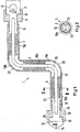
- a volume reduction element 18 is arranged in the cavity 17, which is formed from a plurality of sections 18a, 18b, 18c. Between sections 18a and 18b there is a gap 19a. Between the sections 18b and 18c, a gap 19b is arranged. The gaps 19a and 19b are located in curved sections 20, 21 of the tube 2, respectively.
- the tube 2 is initially stretched straight. Also, the auxiliary member 16 is formed straight and thus can be easily inserted into the straight tube 2 stretched straight.
- the sections 18-18c of the volume reduction element 18 can be easily introduced into the interior of the tube 2 in this state.
- the connectors 5, 10 are inserted into the end sections 3, 4 of the tube 2. Thereafter, the tube 2 is brought into shape and can then be heat-set.
- the gaps 19a, 19b do not interfere with the formation of the curved portions 20,21 of the tube 2.
- the volume reduction member 18 may have more than the illustrated three portions 18a, 18b, 18c. Outside the curved sections 20, 21 of the tube 2, the sections can definitely hit one another, so that no appreciable gap is created.
- the gaps 19a, 19b are shown exaggerated here for reasons of clarity.
- the sections 18a, 18c bear against the auxiliary element 16 with their radial inner side. How to get in Fig. 2 can recognize, the portion 18a of the volume reduction element has a recess 22 which extends along the length of the tube 2.
- a gap 23 is formed, in which, although the volume available for liquid has been greatly reduced.
- the drawing is not to scale to understand here.
- this results in a relatively large wetted surface, which increases the flow resistance for the liquid in the gap 23.
- this flow resistance can lead to problems during the sucking back of the liquid by the pump 8.
- the recess 22, however, provides a flow channel available, in which a much smaller wetted surface is present and thus has a relatively low flow resistance, which allows the sucking back of the liquid from the tube 2.
- the portion 18a is formed as a C-shaped bracket, which consists simply of a longitudinally slotted tube portion whose inner diameter is smaller than the outer diameter of the auxiliary member 16.
- the portion 18a of the volume reduction member 18 can then be clipped onto the auxiliary member 16 before the Auxiliary element 16 is inserted into the tube 2.
- the portion 18a then stops with a certain tension on the auxiliary member 16.
- portion 18a may also be glued or welded to the auxiliary member 16 if necessary.
- the section 18 c of the volume reduction element is designed accordingly and clipped onto the auxiliary element 16.
- the section 18b rests with its radial outer side on the radial inner side of the tube 2.
- a recess 22 is provided which forms a flow channel.
- Fig. 1 The representation of Fig. 1 was chosen to show that there are different ways to position the sections 18a-18c in the cavity 17.
- the auxiliary element 16 enters the second connector 10 and forms an annular gap 24 with the connecting piece 11.
- This annular gap 24 has a cross-sectional area which corresponds to 70% to 130% of a cross-sectional area of the gap 23.
- the cross-sectional area of the annular gap 24 is approximately the same size as the cross-sectional area of the gap 23.
Landscapes
- Engineering & Computer Science (AREA)
- General Engineering & Computer Science (AREA)
- Mechanical Engineering (AREA)
- Chemical & Material Sciences (AREA)
- Chemical Kinetics & Catalysis (AREA)
- Health & Medical Sciences (AREA)
- Toxicology (AREA)
- Combustion & Propulsion (AREA)
- Exhaust Gas After Treatment (AREA)
- Jet Pumps And Other Pumps (AREA)
Description
- Die Erfindung betrifft eine Fluidleitung mit einem Rohr, das einen eingangsseitigen Endabschnitt mit einem ersten Verbinder und einem ausgangsseitigen Endabschnitt mit einem zweiten Verbinder aufweist, wobei im Rohr ein radial innen durch mindestens ein Hilfselement begrenzter Hohlraum ausgebildet ist.
- Dokument
DE 10 2008 018 658 A1 offenbart eine als Medienleitung im Fahrzeugbau einsetzbares beheizbares Leitungselement. Letzteres besteht aus einem äußeren, der Medienführung dienenden Rohr, innerhalb welchem sich ein Heizleiter erstreckt. Dieser besteht aus einem, zwei elektrische Leiter aufnehmenden, aus einem PTC-Kunststoff bestehenden, streifenförmigen Formkörper, an welchem zwei, einander in einer Ebene senkrecht zu dem Formkörper diametral gegenüberliegende Längsrippen angeformt sind. - Dokument
US 5,018,260 A1 offenbart eine doppelwandige Rohranordnung mit einem Innenrohr und einem Außenrohr. Eine verformbare Klammer wird auf das Innenrohr aufgeclipst, um das Innenrohr im Außenrohr zu zentrieren. - Die Erfindung wird im Folgenden in Verbindung mit einer Fluidleitung beschrieben, die zum Transport einer Harnstofflösung (Urea) von einem Vorratsbehälter zu einer Einspritzanordnung verwendet wird. Urea wird mit Hilfe der Einspritzanordnung in einen Abgasstrang eines Dieselmotors eingespritzt, um Stickoxide zu reduzieren.
- Bei niedrigen Temperaturen friert Urea ein. Wenn Urea einfriert, besteht die Gefahr, dass die in der Einspritzanordnung verbliebene Menge an Urea die Einspritzanordnung beschädigt.
- Um das Risiko einer Beschädigung der Einspritzanordnung durch einfrierendes Urea zu vermeiden, kann man nach dem Abstellen des Motors die Harnstofflösung aus der Leitung zurücksaugen, so dass zumindest die Einspritzanordnung von Urea frei wird. Zum Zurücksaugen möchte man gerne die gleiche Pumpe verwenden, die auch zum Fördern von Urea vom Vorratsbehälter zur Einspritzanordnung verwendet wird. Diese Pumpe ist aber in erster Linie eine Förderpumpe, die Urea vom eingangsseitigen Endabschnitt des Rohrs zum ausgangsseitigen Endabschnitt fördert, also mit einem gewissen Druck. Die Saugleistung einer derartigen Pumpe ist in der Regel deutlich schlechter.
- Der Erfindung liegt die Aufgabe zugrunde, die Anforderungen an die Saugleistung einer Pumpe klein zu halten.
- Diese Aufgabe wird erfindungsgemäß durch die Merkmale von Anspruch 1 gelöst.
- Bei einer Urea-Leitung ist im Hohlraum vielfach bereits ein Heizelement angeordnet, das den Hohlraum radial innen begrenzt. Vereinfacht ausgedrückt ist in diesem Fall der Hohlraum als ringförmiger Hohlraum ausgebildet. Das Heizelement kann allerdings auch durch mehrere Elemente gebildet sein oder es können weitere Elemente im Inneren des Rohres angeordnet sein, so dass der Begriff "ringförmig" nicht in allen Fällen zutrifft. Er wird im Folgenden aus Zwecken der Einfachheit verwendet. Das Hilfselement vermindert zwar das freie Volumen im Inneren des Rohres. Dennoch verbleibt ein Volumen, das relativ groß ist und an die Saugleistung der Pumpe eine erhöhte Anforderung stellt. Wenn man nun zusätzlich zu dem Hilfselement ein Volumenreduktionselement im Hohlraum anordnet, dann wird das verbleibende Volumen des Hohlraumes weiter vermindert. Damit vermindert sich auch die mögliche Menge einer Flüssigkeit, die noch im Inneren des Rohres verbleiben kann und die zurückgesaugt werden muss. Je kleiner diese Flüssigkeitsmenge ist, desto geringer ist die Anforderung an die Saugleistung der Pumpe. Erstaunlicherweise reicht es hierbei in vielen Fällen aus, das Volumenreduktionselement nur im ausgangsseitigen Endabschnitt anzuordnen. Wenn die Pumpe dann am eingangsseitigen Endabschnitt die Flüssigkeit aus dem Inneren des Rohres zurücksaugt, dann wird durch die Verringerung des freien Volumens im Bereich des ausgangsseitigen Endabschnitts ein ausreichender Saugdruck erzeugt, um die Einspritzanordnung frei zu saugen. Zusätzlich hat dies den Vorteil, dass die Bereiche des Rohres, die mit dem Volumenreduktionselement versehen sind, relativ schnell leer gesaugt werden können, so dass in diesen Bereichen nur noch Luft vorhanden ist, die dem Saugen der Pumpe einen noch kleineren Widerstand entgegensetzt. Es ergibt sich also insgesamt ein schnelleres Leersaugen der Einspritzanordnung und gegebenenfalls auch der gesamten Fluidleitung.
- Vorzugsweise erstreckt sich das Volumenreduktionselement über den ausgangsseitigen Endabschnitt hinaus in Richtung auf den eingangsseitigen Endabschnitt. Man kann im Grunde das gesamte Rohr mit einem Volumenreduktionselement versehen, um das freie Volumen im Inneren des Rohres kleinzuhalten. Damit ergibt sich zwar ein größerer Strömungswiderstand, der sich dem Durchfluss einer Flüssigkeit vom eingangsseitigen Ende zum ausgangsseitigen Ende entgegensetzt. Bei der Verwendung der Fluidleitung zum Transport von Urea zu einem Dieselmotor ist dies jedoch unkritisch, da hier keine größeren Urea-Mengen schnell bewegt werden müssen.
- Erfindungsgemäß weist das Volumenreduktionselement mehrere Abschnitte auf, wobei zwischen mindestens zwei Abschnitten eine Lücke vorgesehen ist. Dadurch wird die Montage der Leitung erleichtert. Man kann die Abschnitte des Volumenreduktionselements einzeln montieren, was insbesondere bei längeren Leitungen einen gewissen Vorteil darstellt.
- Hierbei ist bevorzugt, dass das Rohr einen gekrümmten Abschnitt aufweist und die Lücke im gekrümmten Abschnitt angeordnet ist. In vielen Fällen wird die Leitung so gefertigt, dass das Hilfselement und das Volumenreduktionselement in ein geradlinig ausgestrecktes Rohr eingesetzt werden. Danach wird das Rohr gebogen, um den gekrümmten Abschnitt zu erzeugen. Gegebenenfalls ist hier eine Erwärmung des Rohres erforderlich. Wenn man im Bereich des gekrümmten Abschnitts eine Lücke zwischen zwei Abschnitten des Volumenreduktionselements vorsieht, dann behindert das Volumenreduktionselement die Ausbildung der Krümmung nicht. Insbesondere verhindert man dadurch einen Verschluss des Innenraums des Rohres im Bereich des gekrümmten Abschnitts.
- Vorzugsweise erstreckt sich das Volumenreduktionselement über die gesamte Länge des Rohres. Damit wird in der gesamten Länge des Rohres das Volumen klein gehalten. Lücken zwischen Abschnitten des Volumenreduktionselements stören dabei praktisch nicht, weil sie das für Flüssigkeit zur Verfügung stehende Volumen, das leer gesaugt werden müsste, nicht übermäßig stark vergrößern.
- Erfindungsgemäß weist das Volumenreduktionselement eine sich entlang der Länge des Rohres erstreckende Ausnehmung auf. Das Volumenreduktionselement vermindert zwar den freien Strömungsquerschnitt für eine Flüssigkeit, die vom eingangsseitigen Ende zum ausgangsseitigen Ende fließt. Es erhöht jedoch die benetzte Fläche, so dass sich daraus ein erhöhter Strömungswiderstand ergibt, der insbesondere beim Zurücksaugen des Fluids wiederum höhere Anforderungen an die Pumpe verursachen könnte. Die Ausnehmung stellt in diesem Fall einen durchgehenden Strömungskanal zur Verfügung, der eine relativ kleine benetzte Fläche und damit auch einen relativ kleinen Strömungswiderstand aufweist. Das für die Flüssigkeit zur Verfügung stehende Volumen wird durch die Ausnehmung nicht übermäßig stark vergrößert.
- Vorzugsweise liegt das Volumenreduktionselement an der radialen Innenseite und/oder an der radialen Außenseite des Hohlraumes an. Damit wird eine definierte Position des Volumenreduktionselements erreicht. In der Regel wird das Volumenreduktionselement nur an der radialen Innenseite oder nur an der radialen Außenseite des Hohlraumes anliegen. Wenn jedoch das Volumenreduktionselement in mehrere Abschnitte unterteilt ist, ist es möglich, einen Teil der Abschnitte an der radialen Innenseite und einen Teil der Abschnitte an der radialen Außenseite des Hohlraumes anliegen zu lassen.
- Hierbei ist bevorzugt, dass das Volumenreduktionselement unter einer Spannung an der radialen Innenseite und/oder an der radialen Außenseite des Hohlraumes anliegt. Damit wird die Reibung zwischen dem Volumenreduktionselement und der radialen Innenseite des Hohlraumes bzw. zwischen dem Volumenreduktionselement und der radialen Außenseite des Hohlraumes relativ groß gemacht, so dass das Volumenreduktionselement nicht durch vorbeiströmende Flüssigkeit verschoben werden kann. Das Volumenreduktionselement klemmt sozusagen im Hohlraum fest.
- Zusätzlich oder alternativ dazu kann vorgesehen sein, dass das Volumenreduktionselement mit der radialen Innenseite und/oder der radialen Außenseite des Hohlraumes verbunden ist. Eine derartige Verbindung kann beispielsweise durch Kleben, Schweißen oder dergleichen realisiert werden. Damit wird das Volumenreduktionselement unverschiebbar im Hohlraum gehalten. Auch ist von Vorteil, wenn das Hilfselement zumindest in dem zweiten Verbinder eintritt und mit einem Anschlussstutzen des zweiten Verbinders einen Ringspalt bildet, wobei der Ringspalt eine Querschnittsfläche aufweist, die den 0,7- bis 1,3-fachen einer Querschnittsfläche des mit dem Volumenreduktionselements versehenen Hohlraumes entspricht. Auch im Verbinder kann dann allenfalls eine relativ kleine Menge an Flüssigkeit verbleiben, die von der Pumpe problemlos zurückgesaugt werden kann.
- Die Erfindung wird im Folgenden anhand eines bevorzugten Ausführungsbeispiels in Verbindung mit der Zeichnung beschrieben. Hierin zeigen:
- Fig. 1
- eine stark schematisierte Schnittansicht einer Fluidleitung und
- Fig. 2
- einen Schnitt II-II nach
Fig. 1 . - Eine Fluidleitung 1 weist ein Rohr 2 auf, das einen eingangsseitigen Endabschnitt 3 und einen ausgangsseitigen Endabschnitt 4 aufweist.
- Am eingangsseitigen Endabschnitt 3 ist ein erster Verbinder 5 angeordnet. Der erste Verbinder 5 weist einen Stutzen 6 auf, auf den das Rohr 2 aufgeschoben ist. Der erste Verbinder 5 weist weiterhin eine Anschlussgeometrie 7 auf, die mit einer schematisch dargestellten Pumpe 8 verbunden ist. Die Pumpe 8 weist, wie dies durch einen Doppelpfeil 9 angedeutet ist, eine umschaltbare Förderrichtung auf, d.h. die Pumpe 8 kann eine Flüssigkeit in die Leitung 1 hineinfördern oder sie kann die Flüssigkeit aus der Leitung 1 heraussaugen.
- Am ausgangsseitigen Endabschnitt 4 ist ein zweiter Verbinder 10 angeordnet. Der zweite Verbinder 10 weist ebenfalls einen Stutzen 11 auf, auf den das Rohr 2 aufgeschoben ist. Der zweite Verbinder 10 weist eine Anschlussgeometrie 12 auf, die mit einer Einspritzanordnung 13 verbunden ist. Die Einspritzanordnung 13 weist eine schematisch dargestellte Düse 14 auf. Es können auch mehrere Düsen vorgesehen sein. Der Düse 14 vorgeschaltet ist ein elektrisch betätigbares Ventil 15, so dass eine Flüssigkeit aus der Leitung 1 gezielt über die Einspritzanordnung 13 ausgegeben werden kann.
- Im Rohr 2 ist eine Hilfseinrichtung 16 angeordnet, die im vorliegenden Fall als Heizstab ausgebildet ist. Die Hilfseinrichtung 16 ist sowohl in den Stutzen 6 des ersten Verbinders 5 als auch in den Stutzen 11 des zweiten Verbinders 10 eingeführt. Die Hilfseinrichtung 16 verlässt den ersten Verbinder 5 und den zweiten Verbinder 10 seitlich, also aus der Zeichenebene heraus, so dass man zumindest in einem der Verbinder 5, 10 dem Hilfselement 16 elektrische Energie zuführen kann, um eine Heizleistung zu erzeugen.
- Zwischen dem Rohr 2 und dem Hilfselement 16 ist ein Hohlraum 17 angeordnet. Wenn lediglich ein einzelnes Hilfselement 16 im Inneren des Rohres 2 angeordnet ist, dann kann der Hohlraum 17 als "ringförmig" bezeichnet werden. Diese Bezeichnung wird aus Gründen der Einfachheit auch beibehalten und gilt auch dann, wenn anstelle eines einzelnen Hilfselements 16 beispielsweise zwei oder mehr Hilfselemente 16 vorgesehen sind, beispielsweise zwei parallel verlaufende Heizdrähte.
- Der Hohlraum 17 hat ein Volumen, das radial außen durch das Rohr 2 und radial innen durch das Hilfselement 16 begrenzt ist. Da das Hilfselement 16 auch durch die Stutzen 6, 11 der Verbinder 5, 10 treten muss und das Rohr 2 auf die Stutzen 6, 11 aufgeschoben ist und somit einen größeren Innendurchmesser als die Stutzen 6, 11 aufweist, hat der Hohlraum 17 zwangsläufig eine relativ große radiale Erstreckung und damit auch ein relativ großes Volumen. Ein großes Volumen stellt an die Saugleistung der Pumpe 8 erhebliche Anforderungen.
- Um diese Anforderungen kleinzuhalten, ist im Hohlraum 17 ein Volumenreduktionselement 18 angeordnet, das aus mehreren Abschnitten 18a, 18b, 18c gebildet ist. Zwischen den Abschnitten 18a und 18b ist eine Lücke 19a. Zwischen den Abschnitten 18b und 18c ist eine Lücke 19b angeordnet. Die Lücken 19a und 19b befinden sich jeweils in gekrümmten Abschnitten 20, 21 des Rohres 2.
- Bei der Herstellung der Fluidleitung 1 ist das Rohr 2 zunächst gerade gestreckt. Auch das Hilfselement 16 ist gerade gestreckt ausgebildet und kann somit problemlos in das gerade gestreckte Rohr 2 eingeschoben werden. Auch die Abschnitte 18-18c des Volumenreduktionselements 18 können in diesem Zustand problemlos in das Innere des Rohres 2 eingebracht werden. Üblicherweise werden auch die Verbinder 5, 10 in die Endabschnitte 3, 4 des Rohres 2 eingesetzt. Danach wird das Rohr 2 in Form gebracht und kann dann thermofixiert werden. Die Lücken 19a, 19b stören dabei die Ausbildung der gekrümmten Abschnitte 20,21 des Rohres 2 nicht.
- Das Volumenreduktionselement 18 kann mehr als die dargestellten drei Abschnitte 18a, 18b, 18c aufweisen. Außerhalb der gekrümmten Abschnitte 20,21 des Rohres 2 können die Abschnitte durchaus aneinander stoßen, so dass keine merkliche Lücke entsteht. Die Lücken 19a, 19b sind hier aus Gründen der Übersicht übertrieben groß dargestellt.
- Die Abschnitte 18a, 18c liegen mit ihrer radialen Innenseite am Hilfselement 16 an. Wie man in
Fig. 2 erkennen kann, weist der Abschnitt 18a des Volumenreduktionselements eine Ausnehmung 22 auf, die sich entlang der Länge des Rohres 2 erstreckt. - Zwischen dem Abschnitt 18a des Volumenreduktionselements 18 und dem Rohr 2 ist ein Spalt 23 ausgebildet, in dem zwar das für Flüssigkeit zur Verfügung stehende Volumen stark vermindert worden ist. Die Zeichnung ist hier nicht maßstäblich zu verstehen. Es ergibt sich allerdings eine relativ große benetzte Fläche, die den Strömungswiderstand für die Flüssigkeit in dem Spalt 23 erhöht. Dieser Strömungswiderstand kann unter Umständen zu Problemen beim Rücksaugen der Flüssigkeit durch die Pumpe 8 führen. Die Ausnehmung 22 stellt hingegen einen Strömungskanal zur Verfügung, bei dem eine weitaus geringere benetzte Fläche vorhanden ist und der somit einen relativ geringen Strömungswiderstand hat, der das Zurücksaugen der Flüssigkeit aus dem Rohr 2 ermöglicht.
- Erfindungsgemäß ist der Abschnitt 18a als C-förmige Klammer ausgebildet, die einfach aus einem in Längsrichtung geschlitzten Rohrabschnitt besteht, dessen Innendurchmesser kleiner ist als der Außendurchmesser des Hilfselements 16. Der Abschnitt 18a des Volumenreduktionselements 18 kann dann auf das Hilfselement 16 aufgeclipst werden, bevor das Hilfselement 16 in das Rohr 2 eingeschoben wird. Der Abschnitt 18a hält dann mit einer gewissen Spannung auf dem Hilfselement 16 fest.
- Natürlich kann der Abschnitt 18a mit dem Hilfselement 16 auch verklebt oder verschweißt werden, wenn dies erforderlich sein sollte.
- Der Abschnitt 18c des Volumenreduktionselements ist entsprechend ausgebildet und auf das Hilfselement 16 aufgeclipst. Der Abschnitt 18b liegt hingegen mit seiner radialen Außenseite an der radialen Innenseite des Rohres 2 an. Auch hier kann man den Abschnitt 18b mit einer Vorspannung radial nach außen versehen, so dass er unter einer gewissen Spannung an der Innenseite des Rohres 2 anliegt. Auch hier ist dann vorteilhafterweise eine Ausnehmung 22 vorgesehen, die einen Strömungskanal bildet.
- Üblicherweise wird man alle Abschnitte 18a-18c entweder an dem Hilfselement 16 festlegen oder an der Innenseite des Rohres 2. Die Darstellung der
Fig. 1 wurde gewählt, um zu zeigen, dass es unterschiedliche Möglichkeiten gibt, um die Abschnitte 18a-18c im Hohlraum 17 zu positionieren. - Die Darstellung in der Zeichnung ist nicht maßstäblich.
- Es ist zu erkennen, dass das Hilfselement 16 in den zweiten Verbinder 10 eintritt und mit dem Anschlussstutzen 11 einen Ringspalt 24 ausbildet. Dieser Ringspalt 24 weist eine Querschnittsfläche auf, die 70 % bis 130 % einer Querschnittsfläche des Spalts 23 entspricht. Mit anderen Worten ist die Querschnittsfläche des Ringspalts 24 etwa gleich groß wie die Querschnittsfläche des Spalts 23.
Claims (10)
- Fluidleitung (1) mit einem Rohr (2), das einen eingangsseitigen Endabschnitt (3) mit einem ersten Verbinder (5) und einen ausgangsseitigen Endabschnitt (4) mit einem zweiten Verbinder (10) aufweist, wobei im Rohr (2) ein radial innen durch mindestens ein Hilfselement (16) begrenzter Hohlraum (17) ausgebildet ist, wobei das Hilfselement (16) als Heizstab ausgebildet ist und im Hohlraum (17) zumindest im Bereich des ausgangsseitigen Endabschnitts (4) ein Volumenreduktionselement (18) angeordnet ist, wobei das Volumenreduktionselement (18) eine sich entlang der Länge des Rohres (2) erstreckende Ausnehmung (22) aufweist, die einen durchgehenden Strömungskanal zur Verfügung stellt, dadurch gekennzeichnet, dass das Volumenreduktionselement (18) mehrere Abschnitte (18a-18c) aufweist, wobei zwischen mindestens zwei Abschnitten (18a, 18b; 18b, 18c) eine Lücke (19a, 19b) vorgesehen ist, wobei einer der Abschnitte (18a) als C-förmige Klammer ausgebildet ist, die aus einem in Längsrichtung geschlitzten Rohrabschnitt besteht, dessen Innendurchmesser kleiner ist als der Außendurchmesser des Hilfselements (16).
- Fluidleitung nach Anspruch 1, dadurch gekennzeichnet, dass sich das Volumenreduktionselement (18) über den ausgangsseitigen Endabschnitt (4) hinaus in Richtung auf den eingangsseitigen Endabschnitt (3) erstreckt.
- Fluidleitung nach einem der Ansprüche 1 oder 2, dadurch gekennzeichnet, dass das Rohr (2) einen gekrümmten Abschnitt (20, 21) aufweist und die Lücke (19a, 19b) im gekrümmten Abschnitt (20,21) angeordnet ist.
- Fluidleitung nach einem der Ansprüche 1 bis 4, dadurch gekennzeichnet, dass sich das Volumenreduktionselement (18) über die gesamte Länge des Rohres (2) erstreckt.
- Fluidleitung nach einem der Ansprüche 1 bis 4, dadurch gekennzeichnet, dass das Volumenreduktionselement (18) an der radialen Innenseite und/oder an der radialen Außenseite des Hohlraumes (17) anliegt.
- Fluidleitung nach Anspruch 5, dadurch gekennzeichnet, dass das Volumenreduktionselement (18) unter einer Spannung an der radialen Innenseite und/oder an der radialen Außenseite des Hohlraumes (17) anliegt.
- Fluidleitung nach Anspruch 5 oder 6, dadurch gekennzeichnet, dass das Volumenreduktionselement (18) mit der radialen Innenseite und/oder der radialen Außenseite des Hohlraums (17) verbunden ist.
- Fluidleitung nach einem der Ansprüche 1 bis 7, dadurch gekennzeichnet, dass das Hilfselement (16) zumindest in den zweiten Verbinder (10) eintritt und mit einem Anschlussstutzen (11) des zweiten Verbinders (10) einen Ringspalt (24) bildet, wobei der Ringspalt (24) eine Querschnittsfläche aufweist, die dem 0,7 - bis 1,3 - fachen einer Querschnittsfläche des mit dem Volumenreduktionselement (18) versehenen Hohlraums (17) entspricht.
- Fluidleitung nach einem der Ansprüche 1 bis 8, dadurch gekennzeichnet, dass diese eine Pumpe (8) und eine Einspritzanordnung (13) aufweist, wobei der erste Verbinder (5) einen Stutzen (6), auf den das Rohr (2) aufgeschoben ist, und eine Anschlussgeometrie (7), die mit der Pumpe (8) verbunden ist, aufweist, wobei die Pumpe (8) eine umschaltbare Förderrichtung aufweist, und wobei der zweite Verbinder (10) einen Stutzen (11), auf den das Rohr (2) aufgeschoben ist, und eine Anschlussgeometrie (12), die mit der Einspritzanordnung (13) verbunden ist, aufweist.
- Verwendung einer Fluidleitung nach Anspruch 9 zum Transport einer Harnstofflösung von einem Vorratsbehälter zu der Einspritzanordnung (13), wobei die Harnstofflösung mit Hilfe der Einspritzanordnung (13) in einen Abgasstrang eines Dieselmotors eingespritzt wird, um Stickoxide zu reduzieren.
Priority Applications (1)
| Application Number | Priority Date | Filing Date | Title |
|---|---|---|---|
| EP19152261.4A EP3495707B1 (de) | 2014-06-17 | 2015-06-16 | Fluidleitung, verwendung einer solchen zum transport einer harnstofflösung und verfahren zur vermeidung des risikos einer beschädigung einer einspritzanordnung eines dieselmotors durch einfrierende harnstofflösung |
Applications Claiming Priority (2)
| Application Number | Priority Date | Filing Date | Title |
|---|---|---|---|
| DE102014108494.2A DE102014108494A1 (de) | 2014-06-17 | 2014-06-17 | Fluidleitung |
| PCT/EP2015/063464 WO2015193304A1 (de) | 2014-06-17 | 2015-06-16 | Fluidleitung |
Related Child Applications (2)
| Application Number | Title | Priority Date | Filing Date |
|---|---|---|---|
| EP19152261.4A Division EP3495707B1 (de) | 2014-06-17 | 2015-06-16 | Fluidleitung, verwendung einer solchen zum transport einer harnstofflösung und verfahren zur vermeidung des risikos einer beschädigung einer einspritzanordnung eines dieselmotors durch einfrierende harnstofflösung |
| EP19152261.4A Division-Into EP3495707B1 (de) | 2014-06-17 | 2015-06-16 | Fluidleitung, verwendung einer solchen zum transport einer harnstofflösung und verfahren zur vermeidung des risikos einer beschädigung einer einspritzanordnung eines dieselmotors durch einfrierende harnstofflösung |
Publications (2)
| Publication Number | Publication Date |
|---|---|
| EP3158250A1 EP3158250A1 (de) | 2017-04-26 |
| EP3158250B1 true EP3158250B1 (de) | 2019-08-28 |
Family
ID=53398111
Family Applications (2)
| Application Number | Title | Priority Date | Filing Date |
|---|---|---|---|
| EP19152261.4A Active EP3495707B1 (de) | 2014-06-17 | 2015-06-16 | Fluidleitung, verwendung einer solchen zum transport einer harnstofflösung und verfahren zur vermeidung des risikos einer beschädigung einer einspritzanordnung eines dieselmotors durch einfrierende harnstofflösung |
| EP15729181.6A Active EP3158250B1 (de) | 2014-06-17 | 2015-06-16 | Fluidleitung |
Family Applications Before (1)
| Application Number | Title | Priority Date | Filing Date |
|---|---|---|---|
| EP19152261.4A Active EP3495707B1 (de) | 2014-06-17 | 2015-06-16 | Fluidleitung, verwendung einer solchen zum transport einer harnstofflösung und verfahren zur vermeidung des risikos einer beschädigung einer einspritzanordnung eines dieselmotors durch einfrierende harnstofflösung |
Country Status (7)
| Country | Link |
|---|---|
| US (1) | US10539262B2 (de) |
| EP (2) | EP3495707B1 (de) |
| JP (1) | JP6351131B2 (de) |
| KR (1) | KR20170016497A (de) |
| CN (1) | CN106461146B (de) |
| DE (1) | DE102014108494A1 (de) |
| WO (1) | WO2015193304A1 (de) |
Families Citing this family (8)
| Publication number | Priority date | Publication date | Assignee | Title |
|---|---|---|---|---|
| DE202017101274U1 (de) * | 2017-03-06 | 2017-03-24 | TI Automotive (Fuldabrück) GmbH | Verbindungsaggregat |
| US10947938B2 (en) | 2017-06-21 | 2021-03-16 | Steere Enterprises, Inc. | Air duct assembly with a secured seal |
| DE102018122597A1 (de) * | 2018-09-14 | 2020-03-19 | Norma Germany Gmbh | Vorrichtung zum Verbinden zweier röhrenförmiger Objekte |
| DE102019103210A1 (de) * | 2019-02-08 | 2020-08-13 | Norma Germany Gmbh | Winkelstück zum fluidkommunizierenden Verbinden von Fluidleitungen eines Fahrzeugs |
| DE102019103209A1 (de) * | 2019-02-08 | 2020-08-13 | Norma Germany Gmbh | Wasserverteilerrohr |
| US20200383177A1 (en) * | 2019-05-31 | 2020-12-03 | Graco Minnesota Inc. | Sensor free heated hose |
| US20220299146A1 (en) * | 2021-03-19 | 2022-09-22 | Akron Brass Company | Fluid monitor elbow |
| CN117307861B (zh) * | 2023-09-27 | 2025-08-01 | 新磊半导体科技(苏州)股份有限公司 | 一种分子束外延设备液氮循环系统排气管加热装置 |
Citations (1)
| Publication number | Priority date | Publication date | Assignee | Title |
|---|---|---|---|---|
| US5018260A (en) * | 1989-05-26 | 1991-05-28 | Asahi/America, Inc. | Supports for double-containment thermoplastic pipe assemblies |
Family Cites Families (33)
| Publication number | Priority date | Publication date | Assignee | Title |
|---|---|---|---|---|
| US2408253A (en) * | 1943-08-27 | 1946-09-24 | Barney A Diebold | Guard or protector for electric cables |
| US2599671A (en) * | 1946-12-07 | 1952-06-10 | Curtiss Wright Corp | Fluid conduit heating means |
| US2750487A (en) * | 1952-08-12 | 1956-06-12 | Turbine Equipment Company | Electric heater |
| US2793917A (en) * | 1953-12-14 | 1957-05-28 | Warren F Ward | Sucker rod protectors |
| US3349619A (en) * | 1959-07-29 | 1967-10-31 | Meriam Instr Company | Laminar flow element and flow meter |
| US3407837A (en) * | 1965-10-20 | 1968-10-29 | Mansfield Sanitary Inc | Sillcock with ice expansion control |
| US3924661A (en) * | 1973-07-16 | 1975-12-09 | Frank G Bornhoffer | Flexible hose storage container |
| JPS5249099B2 (de) | 1973-11-05 | 1977-12-14 | ||
| FR2478161A1 (fr) | 1980-03-11 | 1981-09-18 | Fabre Jean | Perfectionnements apportes aux conduits, enceintes, ou recipients pour fluides, et en particulier pour les liquides |
| US4883943A (en) * | 1987-12-16 | 1989-11-28 | Davco Manufacturing Corporation | Electric heater for fuel tank discharge opening coupling to prevent fuel waxing |
| DE9003635U1 (de) * | 1990-03-06 | 1990-07-05 | Ingenieurbüro H. Lüthin AG, Wettingen | Dehnschlauch zur Verringerung von Druckpulsationen |
| WO1997001017A1 (en) * | 1995-06-20 | 1997-01-09 | Bj Services Company, U.S.A. | Insulated and/or concentric coiled tubing |
| US5749398A (en) * | 1996-02-12 | 1998-05-12 | Kambara; Goro | Solidifiable flexible tube |
| FR2761386B1 (fr) * | 1997-03-25 | 1999-09-03 | Raoul Girod | Dispositif empechant la rupture d'une canalisation en cas de gel |
| US6143988A (en) * | 1997-05-23 | 2000-11-07 | Baker Hughes Incorporated | Coiled tubing supported electrical cable having indentations |
| US6167883B1 (en) * | 1998-01-23 | 2001-01-02 | Respiratory Support Products, Inc. | Medical air hose internal flow heater |
| EP1893852B1 (de) | 2005-06-22 | 2011-12-07 | Eichenauer Heizelemente GmbH & Co. KG | Reduktionsmittelversorgungssystem für einen abgasreinigungskatalysator und heizeinrichtung hierfür |
| US7635008B2 (en) * | 2006-07-18 | 2009-12-22 | Gaphog International, A Utah Llc | Flow restricting device having self-forming conduits |
| FR2905161B1 (fr) * | 2006-08-25 | 2012-04-20 | Inergy Automotive Systems Res | Raccord avec element chauffant integre. |
| DE102008025299A1 (de) * | 2007-06-12 | 2008-12-18 | Contitech Schlauch Gmbh | Anschlussvorrichtung für medienführende, elektrisch beheizbare Schläuche |
| JP4823980B2 (ja) * | 2007-07-30 | 2011-11-24 | ニッタ株式会社 | 加熱・保温チューブを有する装置 |
| DE102008018658A1 (de) * | 2008-04-11 | 2009-10-15 | A. Kayser Automotive Systems Gmbh | Beheizbares Leitungselement für ein Fluid |
| US8028721B2 (en) * | 2008-04-14 | 2011-10-04 | K & H Manufacturing, Llc | Heated garden hose for use cold weather |
| US20100175469A1 (en) * | 2009-01-09 | 2010-07-15 | Ni Frank Zhi | Electrically heated fluid tube |
| DE102010012868A1 (de) * | 2010-03-25 | 2011-09-29 | Gerhard Kurz | Vorrichtung zum Ausbringen eines Mediums mit einer einstellbaren Temperatur |
| US8549840B2 (en) * | 2010-11-12 | 2013-10-08 | Cummins Cal Pacific, Llc | Fluid injector |
| PL2455645T3 (pl) * | 2010-11-17 | 2013-09-30 | Ti Automotive Fuldabrueck Gmbh | Łącznik do połączenia przynajmniej dwóch elementów przyjmujących dla medium płynnego |
| DE102010061271A1 (de) * | 2010-12-15 | 2012-06-21 | Contitech Schlauch Gmbh | Beheizbare Anschlussvorrichtung für medienführende, elektrisch beheizbare Schläuche |
| DE102011102151B4 (de) | 2011-05-20 | 2022-05-19 | Norma Germany Gmbh | Fluidleitung |
| DE102011102148A1 (de) | 2011-05-20 | 2012-11-22 | Norma Germany Gmbh | Fluidleitung |
| FR2993956B1 (fr) * | 2012-07-27 | 2015-05-22 | Coutier Moulage Gen Ind | Ensemble de tuyau pour l’ecoulement d’un fluide et d’un courant et procede pour assembler un tel ensemble de tuyau |
| DE102014102357A1 (de) * | 2014-02-24 | 2015-08-27 | Norma Germany Gmbh | Beheizbare Fluidleitung |
| US20170023164A1 (en) * | 2015-07-24 | 2017-01-26 | Eichenauer Heizelemente Gmbh & Co. Kg | Pipe connector and method for manufacturing a pipe connector |
-
2014
- 2014-06-17 DE DE102014108494.2A patent/DE102014108494A1/de not_active Withdrawn
-
2015
- 2015-06-16 JP JP2016570323A patent/JP6351131B2/ja not_active Expired - Fee Related
- 2015-06-16 EP EP19152261.4A patent/EP3495707B1/de active Active
- 2015-06-16 CN CN201580032154.1A patent/CN106461146B/zh not_active Expired - Fee Related
- 2015-06-16 EP EP15729181.6A patent/EP3158250B1/de active Active
- 2015-06-16 US US15/319,639 patent/US10539262B2/en not_active Expired - Fee Related
- 2015-06-16 KR KR1020177001348A patent/KR20170016497A/ko not_active Ceased
- 2015-06-16 WO PCT/EP2015/063464 patent/WO2015193304A1/de not_active Ceased
Patent Citations (1)
| Publication number | Priority date | Publication date | Assignee | Title |
|---|---|---|---|---|
| US5018260A (en) * | 1989-05-26 | 1991-05-28 | Asahi/America, Inc. | Supports for double-containment thermoplastic pipe assemblies |
Also Published As
| Publication number | Publication date |
|---|---|
| KR20170016497A (ko) | 2017-02-13 |
| WO2015193304A1 (de) | 2015-12-23 |
| US10539262B2 (en) | 2020-01-21 |
| CN106461146B (zh) | 2019-10-18 |
| JP2017525882A (ja) | 2017-09-07 |
| EP3495707A1 (de) | 2019-06-12 |
| EP3495707B1 (de) | 2020-04-29 |
| DE102014108494A1 (de) | 2015-12-17 |
| CN106461146A (zh) | 2017-02-22 |
| JP6351131B2 (ja) | 2018-07-04 |
| EP3158250A1 (de) | 2017-04-26 |
| US20170122478A1 (en) | 2017-05-04 |
Similar Documents
| Publication | Publication Date | Title |
|---|---|---|
| EP3495707B1 (de) | Fluidleitung, verwendung einer solchen zum transport einer harnstofflösung und verfahren zur vermeidung des risikos einer beschädigung einer einspritzanordnung eines dieselmotors durch einfrierende harnstofflösung | |
| EP2525126B1 (de) | Verbinder für eine beheizbare Fluidleitung und beheizbare Fluidleitung | |
| EP2527703B1 (de) | Fluidleitung | |
| EP2910835B1 (de) | Beheizbare Fluidleitung | |
| EP2706280B1 (de) | Steckverbinder | |
| EP3276243B1 (de) | Kraftfahrzeug-fluidleitung | |
| EP3921551B1 (de) | Winkelstück zum fluidkommunizierenden verbinden von fluidleitungen eines fahrzeugs | |
| EP3158251B1 (de) | Beheizbare fluidleitung | |
| EP2759437B1 (de) | Vorrichtung zum Befüllen zumindest eines in einem Kraftfahrzeug angeordneten Kraftstofftanks | |
| EP4397898B1 (de) | Leitungsverbinder mit geringem strömungswiderstand und verwendung eines solchen leitungsverbinders | |
| EP3455475B1 (de) | Vorrichtung und verfahren zum verbessern der rücksaugbarkeit von reduktionsmittel in einem abgasreduktionssystem | |
| DE102010029334A1 (de) | Fluidspeichereinrichtung | |
| DE102017128658B4 (de) | Leitungssystem für ein Fluid führende Leitungen | |
| EP3327261B1 (de) | Abgasbehandlungsanordnung | |
| DE19642580A1 (de) | Stutzen-Schlauch-Verbindung | |
| DE102016104477A1 (de) | Brauseschlauch | |
| DE102014204270B4 (de) | Anordnung aus schlauchartiger Kraftstoffleitung und elektrisch leitfähigem Kontaktelement | |
| EP3394442B1 (de) | Gekapselter kältemittelverdichter | |
| EP3486539A1 (de) | Rohrleitungselement für flüssigkeitsleitungen | |
| DE102011018429A1 (de) | Vorrichtung zum Zuführen von Kraftstoff zu Einspritzventilen einer Brennkraftmaschine | |
| EP2876273B1 (de) | Verbindungsaggregat aus einer beheizbaren Kraftfahrzeugleitung und einem beheizbaren Verbinder | |
| DE102007053508A1 (de) | Anordnung mit zumindest zwei Hohlkörpern und einem die Hohlkörper verbindenden Steckstück sowie ein Verfahren zum Verbinden von zwei Hohlkörpern mit einem Steckstück | |
| EP2450176A1 (de) | Heizwendelschweissfitting | |
| DE102014209728A1 (de) | Kraftstoffversorgungssystem | |
| CH705587A1 (de) | Verbindungsglied für Rohrleitungen. |
Legal Events
| Date | Code | Title | Description |
|---|---|---|---|
| STAA | Information on the status of an ep patent application or granted ep patent |
Free format text: STATUS: THE INTERNATIONAL PUBLICATION HAS BEEN MADE |
|
| PUAI | Public reference made under article 153(3) epc to a published international application that has entered the european phase |
Free format text: ORIGINAL CODE: 0009012 |
|
| STAA | Information on the status of an ep patent application or granted ep patent |
Free format text: STATUS: REQUEST FOR EXAMINATION WAS MADE |
|
| 17P | Request for examination filed |
Effective date: 20161219 |
|
| AK | Designated contracting states |
Kind code of ref document: A1 Designated state(s): AL AT BE BG CH CY CZ DE DK EE ES FI FR GB GR HR HU IE IS IT LI LT LU LV MC MK MT NL NO PL PT RO RS SE SI SK SM TR |
|
| AX | Request for extension of the european patent |
Extension state: BA ME |
|
| DAV | Request for validation of the european patent (deleted) | ||
| DAX | Request for extension of the european patent (deleted) | ||
| STAA | Information on the status of an ep patent application or granted ep patent |
Free format text: STATUS: EXAMINATION IS IN PROGRESS |
|
| 17Q | First examination report despatched |
Effective date: 20180108 |
|
| REG | Reference to a national code |
Ref country code: DE Ref legal event code: R079 Ref document number: 502015010157 Country of ref document: DE Free format text: PREVIOUS MAIN CLASS: F16L0053000000 Ipc: F16L0053380000 |
|
| GRAP | Despatch of communication of intention to grant a patent |
Free format text: ORIGINAL CODE: EPIDOSNIGR1 |
|
| STAA | Information on the status of an ep patent application or granted ep patent |
Free format text: STATUS: GRANT OF PATENT IS INTENDED |
|
| RIC1 | Information provided on ipc code assigned before grant |
Ipc: F16L 55/027 20060101ALN20190404BHEP Ipc: F16L 53/38 20180101AFI20190404BHEP |
|
| INTG | Intention to grant announced |
Effective date: 20190503 |
|
| GRAS | Grant fee paid |
Free format text: ORIGINAL CODE: EPIDOSNIGR3 |
|
| GRAA | (expected) grant |
Free format text: ORIGINAL CODE: 0009210 |
|
| STAA | Information on the status of an ep patent application or granted ep patent |
Free format text: STATUS: THE PATENT HAS BEEN GRANTED |
|
| AK | Designated contracting states |
Kind code of ref document: B1 Designated state(s): AL AT BE BG CH CY CZ DE DK EE ES FI FR GB GR HR HU IE IS IT LI LT LU LV MC MK MT NL NO PL PT RO RS SE SI SK SM TR |
|
| REG | Reference to a national code |
Ref country code: GB Ref legal event code: FG4D Free format text: NOT ENGLISH |
|
| REG | Reference to a national code |
Ref country code: CH Ref legal event code: EP |
|
| REG | Reference to a national code |
Ref country code: DE Ref legal event code: R096 Ref document number: 502015010157 Country of ref document: DE |
|
| REG | Reference to a national code |
Ref country code: AT Ref legal event code: REF Ref document number: 1172841 Country of ref document: AT Kind code of ref document: T Effective date: 20190915 |
|
| REG | Reference to a national code |
Ref country code: IE Ref legal event code: FG4D Free format text: LANGUAGE OF EP DOCUMENT: GERMAN |
|
| REG | Reference to a national code |
Ref country code: NL Ref legal event code: MP Effective date: 20190828 |
|
| REG | Reference to a national code |
Ref country code: LT Ref legal event code: MG4D |
|
| PG25 | Lapsed in a contracting state [announced via postgrant information from national office to epo] |
Ref country code: LT Free format text: LAPSE BECAUSE OF FAILURE TO SUBMIT A TRANSLATION OF THE DESCRIPTION OR TO PAY THE FEE WITHIN THE PRESCRIBED TIME-LIMIT Effective date: 20190828 Ref country code: HR Free format text: LAPSE BECAUSE OF FAILURE TO SUBMIT A TRANSLATION OF THE DESCRIPTION OR TO PAY THE FEE WITHIN THE PRESCRIBED TIME-LIMIT Effective date: 20190828 Ref country code: NL Free format text: LAPSE BECAUSE OF FAILURE TO SUBMIT A TRANSLATION OF THE DESCRIPTION OR TO PAY THE FEE WITHIN THE PRESCRIBED TIME-LIMIT Effective date: 20190828 Ref country code: SE Free format text: LAPSE BECAUSE OF FAILURE TO SUBMIT A TRANSLATION OF THE DESCRIPTION OR TO PAY THE FEE WITHIN THE PRESCRIBED TIME-LIMIT Effective date: 20190828 Ref country code: BG Free format text: LAPSE BECAUSE OF FAILURE TO SUBMIT A TRANSLATION OF THE DESCRIPTION OR TO PAY THE FEE WITHIN THE PRESCRIBED TIME-LIMIT Effective date: 20191128 Ref country code: NO Free format text: LAPSE BECAUSE OF FAILURE TO SUBMIT A TRANSLATION OF THE DESCRIPTION OR TO PAY THE FEE WITHIN THE PRESCRIBED TIME-LIMIT Effective date: 20191128 Ref country code: FI Free format text: LAPSE BECAUSE OF FAILURE TO SUBMIT A TRANSLATION OF THE DESCRIPTION OR TO PAY THE FEE WITHIN THE PRESCRIBED TIME-LIMIT Effective date: 20190828 Ref country code: PT Free format text: LAPSE BECAUSE OF FAILURE TO SUBMIT A TRANSLATION OF THE DESCRIPTION OR TO PAY THE FEE WITHIN THE PRESCRIBED TIME-LIMIT Effective date: 20191230 |
|
| PG25 | Lapsed in a contracting state [announced via postgrant information from national office to epo] |
Ref country code: ES Free format text: LAPSE BECAUSE OF FAILURE TO SUBMIT A TRANSLATION OF THE DESCRIPTION OR TO PAY THE FEE WITHIN THE PRESCRIBED TIME-LIMIT Effective date: 20190828 Ref country code: RS Free format text: LAPSE BECAUSE OF FAILURE TO SUBMIT A TRANSLATION OF THE DESCRIPTION OR TO PAY THE FEE WITHIN THE PRESCRIBED TIME-LIMIT Effective date: 20190828 Ref country code: IS Free format text: LAPSE BECAUSE OF FAILURE TO SUBMIT A TRANSLATION OF THE DESCRIPTION OR TO PAY THE FEE WITHIN THE PRESCRIBED TIME-LIMIT Effective date: 20191228 Ref country code: LV Free format text: LAPSE BECAUSE OF FAILURE TO SUBMIT A TRANSLATION OF THE DESCRIPTION OR TO PAY THE FEE WITHIN THE PRESCRIBED TIME-LIMIT Effective date: 20190828 Ref country code: GR Free format text: LAPSE BECAUSE OF FAILURE TO SUBMIT A TRANSLATION OF THE DESCRIPTION OR TO PAY THE FEE WITHIN THE PRESCRIBED TIME-LIMIT Effective date: 20191129 Ref country code: AL Free format text: LAPSE BECAUSE OF FAILURE TO SUBMIT A TRANSLATION OF THE DESCRIPTION OR TO PAY THE FEE WITHIN THE PRESCRIBED TIME-LIMIT Effective date: 20190828 |
|
| PG25 | Lapsed in a contracting state [announced via postgrant information from national office to epo] |
Ref country code: TR Free format text: LAPSE BECAUSE OF FAILURE TO SUBMIT A TRANSLATION OF THE DESCRIPTION OR TO PAY THE FEE WITHIN THE PRESCRIBED TIME-LIMIT Effective date: 20190828 |
|
| PG25 | Lapsed in a contracting state [announced via postgrant information from national office to epo] |
Ref country code: RO Free format text: LAPSE BECAUSE OF FAILURE TO SUBMIT A TRANSLATION OF THE DESCRIPTION OR TO PAY THE FEE WITHIN THE PRESCRIBED TIME-LIMIT Effective date: 20190828 Ref country code: IT Free format text: LAPSE BECAUSE OF FAILURE TO SUBMIT A TRANSLATION OF THE DESCRIPTION OR TO PAY THE FEE WITHIN THE PRESCRIBED TIME-LIMIT Effective date: 20190828 Ref country code: EE Free format text: LAPSE BECAUSE OF FAILURE TO SUBMIT A TRANSLATION OF THE DESCRIPTION OR TO PAY THE FEE WITHIN THE PRESCRIBED TIME-LIMIT Effective date: 20190828 Ref country code: DK Free format text: LAPSE BECAUSE OF FAILURE TO SUBMIT A TRANSLATION OF THE DESCRIPTION OR TO PAY THE FEE WITHIN THE PRESCRIBED TIME-LIMIT Effective date: 20190828 Ref country code: PL Free format text: LAPSE BECAUSE OF FAILURE TO SUBMIT A TRANSLATION OF THE DESCRIPTION OR TO PAY THE FEE WITHIN THE PRESCRIBED TIME-LIMIT Effective date: 20190828 |
|
| PG25 | Lapsed in a contracting state [announced via postgrant information from national office to epo] |
Ref country code: SK Free format text: LAPSE BECAUSE OF FAILURE TO SUBMIT A TRANSLATION OF THE DESCRIPTION OR TO PAY THE FEE WITHIN THE PRESCRIBED TIME-LIMIT Effective date: 20190828 Ref country code: IS Free format text: LAPSE BECAUSE OF FAILURE TO SUBMIT A TRANSLATION OF THE DESCRIPTION OR TO PAY THE FEE WITHIN THE PRESCRIBED TIME-LIMIT Effective date: 20200224 Ref country code: SM Free format text: LAPSE BECAUSE OF FAILURE TO SUBMIT A TRANSLATION OF THE DESCRIPTION OR TO PAY THE FEE WITHIN THE PRESCRIBED TIME-LIMIT Effective date: 20190828 Ref country code: CZ Free format text: LAPSE BECAUSE OF FAILURE TO SUBMIT A TRANSLATION OF THE DESCRIPTION OR TO PAY THE FEE WITHIN THE PRESCRIBED TIME-LIMIT Effective date: 20190828 |
|
| REG | Reference to a national code |
Ref country code: DE Ref legal event code: R097 Ref document number: 502015010157 Country of ref document: DE |
|
| PLBE | No opposition filed within time limit |
Free format text: ORIGINAL CODE: 0009261 |
|
| STAA | Information on the status of an ep patent application or granted ep patent |
Free format text: STATUS: NO OPPOSITION FILED WITHIN TIME LIMIT |
|
| PG2D | Information on lapse in contracting state deleted |
Ref country code: IS |
|
| 26N | No opposition filed |
Effective date: 20200603 |
|
| PG25 | Lapsed in a contracting state [announced via postgrant information from national office to epo] |
Ref country code: SI Free format text: LAPSE BECAUSE OF FAILURE TO SUBMIT A TRANSLATION OF THE DESCRIPTION OR TO PAY THE FEE WITHIN THE PRESCRIBED TIME-LIMIT Effective date: 20190828 |
|
| PG25 | Lapsed in a contracting state [announced via postgrant information from national office to epo] |
Ref country code: MC Free format text: LAPSE BECAUSE OF FAILURE TO SUBMIT A TRANSLATION OF THE DESCRIPTION OR TO PAY THE FEE WITHIN THE PRESCRIBED TIME-LIMIT Effective date: 20190828 |
|
| REG | Reference to a national code |
Ref country code: CH Ref legal event code: PL |
|
| PG25 | Lapsed in a contracting state [announced via postgrant information from national office to epo] |
Ref country code: LU Free format text: LAPSE BECAUSE OF NON-PAYMENT OF DUE FEES Effective date: 20200616 |
|
| REG | Reference to a national code |
Ref country code: BE Ref legal event code: MM Effective date: 20200630 |
|
| PG25 | Lapsed in a contracting state [announced via postgrant information from national office to epo] |
Ref country code: CH Free format text: LAPSE BECAUSE OF NON-PAYMENT OF DUE FEES Effective date: 20200630 Ref country code: IE Free format text: LAPSE BECAUSE OF NON-PAYMENT OF DUE FEES Effective date: 20200616 Ref country code: LI Free format text: LAPSE BECAUSE OF NON-PAYMENT OF DUE FEES Effective date: 20200630 |
|
| PG25 | Lapsed in a contracting state [announced via postgrant information from national office to epo] |
Ref country code: BE Free format text: LAPSE BECAUSE OF NON-PAYMENT OF DUE FEES Effective date: 20200630 |
|
| PGFP | Annual fee paid to national office [announced via postgrant information from national office to epo] |
Ref country code: FR Payment date: 20210625 Year of fee payment: 7 Ref country code: DE Payment date: 20210629 Year of fee payment: 7 |
|
| REG | Reference to a national code |
Ref country code: AT Ref legal event code: MM01 Ref document number: 1172841 Country of ref document: AT Kind code of ref document: T Effective date: 20200616 |
|
| PGFP | Annual fee paid to national office [announced via postgrant information from national office to epo] |
Ref country code: GB Payment date: 20210628 Year of fee payment: 7 |
|
| PG25 | Lapsed in a contracting state [announced via postgrant information from national office to epo] |
Ref country code: AT Free format text: LAPSE BECAUSE OF NON-PAYMENT OF DUE FEES Effective date: 20200616 |
|
| PG25 | Lapsed in a contracting state [announced via postgrant information from national office to epo] |
Ref country code: MT Free format text: LAPSE BECAUSE OF FAILURE TO SUBMIT A TRANSLATION OF THE DESCRIPTION OR TO PAY THE FEE WITHIN THE PRESCRIBED TIME-LIMIT Effective date: 20190828 Ref country code: CY Free format text: LAPSE BECAUSE OF FAILURE TO SUBMIT A TRANSLATION OF THE DESCRIPTION OR TO PAY THE FEE WITHIN THE PRESCRIBED TIME-LIMIT Effective date: 20190828 |
|
| PG25 | Lapsed in a contracting state [announced via postgrant information from national office to epo] |
Ref country code: MK Free format text: LAPSE BECAUSE OF FAILURE TO SUBMIT A TRANSLATION OF THE DESCRIPTION OR TO PAY THE FEE WITHIN THE PRESCRIBED TIME-LIMIT Effective date: 20190828 |
|
| REG | Reference to a national code |
Ref country code: DE Ref legal event code: R119 Ref document number: 502015010157 Country of ref document: DE |
|
| GBPC | Gb: european patent ceased through non-payment of renewal fee |
Effective date: 20220616 |
|
| PG25 | Lapsed in a contracting state [announced via postgrant information from national office to epo] |
Ref country code: FR Free format text: LAPSE BECAUSE OF NON-PAYMENT OF DUE FEES Effective date: 20220630 |
|
| PG25 | Lapsed in a contracting state [announced via postgrant information from national office to epo] |
Ref country code: GB Free format text: LAPSE BECAUSE OF NON-PAYMENT OF DUE FEES Effective date: 20220616 Ref country code: DE Free format text: LAPSE BECAUSE OF NON-PAYMENT OF DUE FEES Effective date: 20230103 |