EP3158172B1 - Trägermodul fur einen ohc-ventiltrieb einer brennkraftmaschine - Google Patents
Trägermodul fur einen ohc-ventiltrieb einer brennkraftmaschine Download PDFInfo
- Publication number
- EP3158172B1 EP3158172B1 EP15731503.7A EP15731503A EP3158172B1 EP 3158172 B1 EP3158172 B1 EP 3158172B1 EP 15731503 A EP15731503 A EP 15731503A EP 3158172 B1 EP3158172 B1 EP 3158172B1
- Authority
- EP
- European Patent Office
- Prior art keywords
- carrier module
- base region
- support walls
- module according
- lever
- Prior art date
- Legal status (The legal status is an assumption and is not a legal conclusion. Google has not performed a legal analysis and makes no representation as to the accuracy of the status listed.)
- Not-in-force
Links
- 238000002485 combustion reaction Methods 0.000 title claims description 4
- 238000000926 separation method Methods 0.000 claims description 4
- 238000004080 punching Methods 0.000 claims description 3
- 229910052751 metal Inorganic materials 0.000 claims description 2
- 239000002184 metal Substances 0.000 claims description 2
- 238000000034 method Methods 0.000 claims description 2
- 230000015572 biosynthetic process Effects 0.000 claims 1
- 238000005452 bending Methods 0.000 description 4
- 229910000831 Steel Inorganic materials 0.000 description 2
- 229910052782 aluminium Inorganic materials 0.000 description 2
- XAGFODPZIPBFFR-UHFFFAOYSA-N aluminium Chemical compound [Al] XAGFODPZIPBFFR-UHFFFAOYSA-N 0.000 description 2
- 238000005516 engineering process Methods 0.000 description 2
- 239000010959 steel Substances 0.000 description 2
- RTAQQCXQSZGOHL-UHFFFAOYSA-N Titanium Chemical compound [Ti] RTAQQCXQSZGOHL-UHFFFAOYSA-N 0.000 description 1
- 230000007613 environmental effect Effects 0.000 description 1
- 230000002349 favourable effect Effects 0.000 description 1
- 239000000835 fiber Substances 0.000 description 1
- 239000003562 lightweight material Substances 0.000 description 1
- 239000010687 lubricating oil Substances 0.000 description 1
- 238000004519 manufacturing process Methods 0.000 description 1
- 239000000463 material Substances 0.000 description 1
- 239000003921 oil Substances 0.000 description 1
- 239000002245 particle Substances 0.000 description 1
- 239000004033 plastic Substances 0.000 description 1
- 229920003023 plastic Polymers 0.000 description 1
Images

Classifications
-
- F—MECHANICAL ENGINEERING; LIGHTING; HEATING; WEAPONS; BLASTING
- F01—MACHINES OR ENGINES IN GENERAL; ENGINE PLANTS IN GENERAL; STEAM ENGINES
- F01L—CYCLICALLY OPERATING VALVES FOR MACHINES OR ENGINES
- F01L1/00—Valve-gear or valve arrangements, e.g. lift-valve gear
- F01L1/12—Transmitting gear between valve drive and valve
- F01L1/18—Rocking arms or levers
- F01L1/181—Centre pivot rocking arms
-
- F—MECHANICAL ENGINEERING; LIGHTING; HEATING; WEAPONS; BLASTING
- F01—MACHINES OR ENGINES IN GENERAL; ENGINE PLANTS IN GENERAL; STEAM ENGINES
- F01L—CYCLICALLY OPERATING VALVES FOR MACHINES OR ENGINES
- F01L1/00—Valve-gear or valve arrangements, e.g. lift-valve gear
- F01L1/02—Valve drive
- F01L1/04—Valve drive by means of cams, camshafts, cam discs, eccentrics or the like
- F01L1/047—Camshafts
- F01L1/053—Camshafts overhead type
-
- F—MECHANICAL ENGINEERING; LIGHTING; HEATING; WEAPONS; BLASTING
- F01—MACHINES OR ENGINES IN GENERAL; ENGINE PLANTS IN GENERAL; STEAM ENGINES
- F01L—CYCLICALLY OPERATING VALVES FOR MACHINES OR ENGINES
- F01L1/00—Valve-gear or valve arrangements, e.g. lift-valve gear
- F01L1/02—Valve drive
- F01L1/04—Valve drive by means of cams, camshafts, cam discs, eccentrics or the like
- F01L1/047—Camshafts
- F01L2001/0476—Camshaft bearings
-
- F—MECHANICAL ENGINEERING; LIGHTING; HEATING; WEAPONS; BLASTING
- F01—MACHINES OR ENGINES IN GENERAL; ENGINE PLANTS IN GENERAL; STEAM ENGINES
- F01L—CYCLICALLY OPERATING VALVES FOR MACHINES OR ENGINES
- F01L1/00—Valve-gear or valve arrangements, e.g. lift-valve gear
- F01L1/02—Valve drive
- F01L1/04—Valve drive by means of cams, camshafts, cam discs, eccentrics or the like
- F01L1/047—Camshafts
- F01L1/053—Camshafts overhead type
- F01L2001/0535—Single overhead camshafts [SOHC]
Definitions
- the invention relates to a carrier module for an OHC valve drive of an internal combustion engine, with two upright and mutually spaced support walls, in which at least one camshaft and at least one lever axis with one or more cam followers thereon, the support walls each bridging, are stored, wherein the carrier module in the Foot area with a cylinder head is connectable.
- Generic carrier modules are, for example, in single-cylinder motorcycle engines with 2V technology in use and made of cast aluminum (see valve engine Hyundai engine KRM / KVS, installed in Hyundai CG 150 Titan (Brazil)).
- the levers for actuating the two gas exchange valves sit on separate shafts.
- Such a carrier module also in the document US2009 / 101096 described, is relatively massive, requires unnecessary rework and takes up too much space. Ultimately, it is too expensive for mass production.
- this object is achieved in that the supporting walls with the present as a plate foot area form a one-piece, obtained from sheet metal by separating unit and are bent up from the foot.
- a lightweight and compact carrier module is particularly, but not exclusively, available for motorcycles, boats, or minisite engines.
- a module should be used in single-cylinder engines.
- the protection of this invention also extends to a support module with holes in the support walls and only the possibility of receiving camshaft (s) and lever axis (s), therefore, without the latter components.
- the unit preferably, but not exclusively, to be formed by a separation process such as punching with subsequent bending up the support walls.
- the partial separation of the support walls from the foot area can take place in one go with the separation of the foot area from the board / the strip or in a subsequent method step.
- the carrier module according to the invention is designed to accommodate only a central, short-building camshaft and at least one lever axis flanking the camshaft, wherein preferably an inlet and an outlet lever axis each mounted thereon cam followers (at least one per axle) are provided and more than one camshaft are used can.
- the supporting walls can be bent upwards from the foot area, their head areas advantageously lying on the outer edge of the foot area prior to bending up, and ultimately a middle bar remaining in the foot area.
- the foot area claimed at the edge comparatively little footprint. Collisions with environmental components may be avoided.
- the foot area has, as further proposed, in the region of its edges openings, which may be, for example, punched holes.
- the openings serve, for the mounting case of the support module on the cylinder head, an engagement of, for example, screws or centering pins.
- camshaft (s) and lever axis (s) can also run directly into bores of the support plates, which bores may possibly not be finished, which has a favorable effect on the cost of the support module.
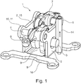
- the support module 1 has, as both figures reveal, two upright and mutually spaced support walls 2, in which a camshaft 3 sits centrally, which is flanked on both sides by a lever axis 4, 5.
- the lever shaft 4 carries a cam follower lever 6, which serves to actuate an intake valve, whereas on the lever shaft 5, a cam follower lever 7 is attached, via which an outlet valve can be actuated. Possibly. the levers 6, 7 can also act on bridges, so that several equally acting gas exchange valves can be actuated simultaneously.
- the support walls 2 are based on a present as a plate foot area 8 and are integrally connected thereto. In this case, the contour of the support walls 2 by punching, leaving a bending edge, separated from the foot area 8 and then the support walls 2 are bent towards each other too. In the foot area 8 thus remains a central web 9 between the support walls. 2
- lever shafts 4, 5 are mounted in flared lugs 10 of the support walls 2, which lie in the top edge portion 11 of the support walls 2.
- 10 free space is formed below the tabs.
Landscapes
- Engineering & Computer Science (AREA)
- Mechanical Engineering (AREA)
- General Engineering & Computer Science (AREA)
- Valve-Gear Or Valve Arrangements (AREA)
Description
- Die Erfindung betrifft ein Trägermodul für einen OHC-Ventiltrieb einer Brennkraftmaschine, mit zwei aufrechten und zueinander beabstandeten Tragwänden, in denen wenigstens eine Nockenwelle sowie zumindest eine Hebelachse mit einem oder mehreren Nockenfolgehebeln hierauf, die Tragwände jeweils überbrückend, gelagert sind, wobei das Trägermodul in dessen Fußbereich mit einem Zylinderkopf verbindbar ist.
- Gattungsgemäße Trägermodule sind bspw. bei Einzylinder-Motorradmotoren mit 2V-Technik im Einsatz und bestehen aus Aluminiumguss (s. Ventiltrieb Honda-Motor KRM/KVS, verbaut in Honda CG 150 Titan (Brasilien)). Die Hebel zur Betätigung der beiden Gaswechselventile sitzen auf separaten Wellen. Ein derartiges Trägermodul, auch im Dokument
US2009/101096 beschrieben, ist vergleichsweise massiv, benötigt unnötig Nacharbeit und nimmt zu viel Bauraum ein. Letztlich ist es für die Massenfertigung zu teuer. - Es ist Aufgabe der Erfindung, ein Trägermodul ohne die vorgenannten Nachteile zu kreieren.
- Erfindungsgemäß wird diese Aufgabe dadurch gelöst, dass die Tragwände mit dem als Platte vorliegenden Fußbereich eine einteilige, aus Blech durch Trennen gewonnene Einheit bilden sowie aus dem Fußbereich hochgebogen sind.
- Somit liegt ein leichtbauendes und kompaktes Trägermodul insbesondere, jedoch nicht ausschließlich, für Krafträder-, Boots- oder Kleingerätemotoren vor. Bevorzugt soll ein derartiges Modul bei Einzylindermotoren verwendet werden. Es ist jedoch auch ein Einsatz bei Motoren mit einer Zylinderzahl >1 denkbar und vorgesehen.
- Der Schutz dieser Erfindung erstreckt sich auch auf ein Trägermodul mit Bohrungen in dessen Tragwänden sowie lediglich der Möglichkeit zur Aufnahme von Nockenwelle(n) und Hebelachse(n), demnach ohne die letztgenannten Bauteile.
- Als Blech kommt insbesondere Stahlblech (Platine / Band) infrage, wobei die Einheit (Tragwände und Fußbereich) vorzugsweise, jedoch nicht ausschließlich, durch einen Trennvorgang wie Stanzen mit anschließendem Hochbiegen der Tragwände gebildet werden soll. Das partielle Trennen der Tragwände aus dem Fußbereich kann in einem Zug mit dem Trennen des Fußbereichs aus der Platine / dem Band oder in einem anschließenden Verfahrensschritt erfolgen.
- Anstelle des o. g. Stahlwerkstoffs für die Einheit bieten sich auch andere Leichtbauwerkstoffe wie ggf. Aluminiumblech, auch paketiert oder anderweitig verstärkt, Kunstoffe, auch faser- oder partikelverstärkt, etc. an.
- Das erfindungsgemäße Trägermodul ist zur Aufnahme lediglich einer mittigen, kurzbauenden Nockenwelle und zumindest einer die Nockenwelle flankierenden Hebelachse ausgelegt, wobei vorzugsweise eine Einlass- und eine Auslasshebelachse mit jeweils darauf montierten Nockenfolgehebeln (wenigstens einer je Achse) vorgesehen sind und auch mehr als eine Nockenwelle eingesetzt werden kann.
- Gemäß einer Fortbildung der Erfindung können die Tragwände aus dem Fußbereich aufeinander zu hochgebogen werden, wobei deren Kopfbereiche vor dem Hochbiegen zweckmäßigerweise am Außenrand des Fußbereichs liegen und im Fußbereich letztlich ein Mittelsteg verbleibt. Somit beansprucht der Fußbereich randseitig vergleichsweise wenig Stellfläche. Kollisionen mit Umgebungsbauteilen werden unter Umständen vermieden.
- Alternativ hierzu ist es vorgeschlagen, einen mittigen Trennspalt im Fußbereich vorzusehen und die Tragwände voneinander weg hochzubiegen. Der Fußbereich erlangt hierdurch eine kasten- oder rahmenähnliche Ausbildung.
- Der Fußbereich hat, wie weiterhin vorgeschlagen, im Bereich seiner Kanten Öffnungen, die bspw. gestanzte Löcher sein können. Die Öffnungen dienen, für den Befestigungsfall des Trägermoduls am Zylinderkopf, einem Eingriff von bspw. Schrauben oder Zentrierstiften.
- Die Nockenwelle(n) und Hebelachse(n) können auch unmittelbar in Bohrungen der Tragplatten verlaufen, welche Bohrungen ggf. nicht feinbearbeitet sein können, was sich günstig auf die Kosten des Trägermoduls auswirkt. Vorgesehen ist es jedoch auch, die Bohrungen mit separaten Hülsen zu versehen, welche bspw. eingepresst sind und auch Wälzlager aufnehmen können.
- Die Erfindung geht aus der Zeichnung hervor.
-
Figur 1 zeigt eine räumliche Seitenansicht des Trägermoduls und -
Figur 2 zeigt eine räumliche Ansicht auf das Trägermodul von oben. - Dargestellt ist in beiden Figuren ein stanz-biegetechnisch aus Stahlblech hergestelltes Trägermodul 1 für einen OHC-Ventiltrieb einer einzylindrigen Motorrad-Brennkraftmaschine.
- Das Trägermodul 1 hat, wie beide Figuren offenbaren, zwei aufrechte und zueinander beabstandete Tragwände 2, in denen mittig eine Nockenwelle 3 sitzt, welche beidseits von einer Hebelachse 4, 5 flankiert ist. Die Hebelachse 4 trägt einen Nockenfolgehebel 6, welcher der Betätigung eines Einlassventils dient, wohingegen auf der Hebelachse 5 ein Nockenfolgehebel 7 befestigt ist, über welchen ein Auslassventil aktuiert werden kann. Ggf. können die Hebel 6, 7 auch auf Brücken einwirken, so dass gleichzeitig mehrere gleichwirkende Gaswechselventile betätigt werden können.
- Die Tragwände 2 gehen von einem als Platte vorliegenden Fußbereich 8 aus und sind einteilig mit diesem verbunden. Dabei wird die Kontur der Tragwände 2 durch Stanzen, unter Verbleib einer Biegekante, aus dem Fußbereich 8 getrennt und anschließend werden die Tragwände 2 aufeinander zu hochgebogen. Im Fußbereich 8 verbleibt somit ein Mittelsteg 9 zwischen den Tragwänden 2.
- Wie am besten aus
Figur 1 entnehmbar ist, sind die Hebelachsen 4, 5 in ausgestellten Laschen 10 der Tragwände 2 gelagert, welche im Kopfkantenbereich 11 der Tragwände 2 liegen. Somit ist unterhalb der Laschen 10 freier Bauraum gebildet. - Im Abschnitt von laschenartig wegstehenden Kanten 12 des Fußbereichs 8 sind Öffnungen 13 zum Verschrauben / Zentrierverstiften des Trägermoduls 1 mit dem Zylinderkopf gestanzt.
- Last but not least ist an der rechten Tragwand 2 nach
Figur 1 ein Ölsteigröhrchen 14 eingezeichnet, welches dort angeklipst ist und einer Weiterleitung von Schmieröl in Richtung Zylinderkopfdeckel (nicht dargestellt) dient. -
- 1) Trägermodul
- 2) Tragwand
- 3) Nockenwelle
- 4) Hebelachse (Einlass)
- 5) Hebelachse (Auslass)
- 6) Nockenfolgehebel
- 7) Nockenfolgehebel
- 8) Fußbereich
- 9) Mittelsteg
- 10) Lasche
- 11) Kopfkantenbereich
- 12) Kante (Fußbereich)
- 13) Öffnung
- 14) Ölsteigröhrchen
- 15) Kopfbereich
- 16) Außenrand
Claims (10)
- Trägermodul (1) für einen OHC-Ventiltrieb einer Brennkraftmaschine, mit zwei aufrechten und zueinander beabstandeten Tragwänden (2), in denen wenigstens eine Nockenwelle (3) sowie zumindest eine Hebelachse (4, 5) mit einem oder mehreren Nockenfolgehebeln (6, 7) hierauf, die Tragwände (2) jeweils überbrückend, gelagert sind, wobei das Trägermodul (1) in dessen Fußbereich (8) mit einem Zylinderkopf verbindbar ist, dadurch gekennzeichnet, dass die Tragwände (2) mit dem als Platte vorliegenden Fußbereich (8) eine einteilige, aus Blech durch Trennen gewonnene Einheit bilden sowie aus dem Fußbereich (8) hochgebogen sind.
- Trägermodul nach Anspruch 1, dadurch gekennzeichnet, dass als Trennverfahren Stanzen appliziert ist.
- Trägermodul nach Anspruch 1, dadurch gekennzeichnet, dass die Tragwände (2), unter Verbleib eines diese verbindenden Mittelstegs (9) im Fußbereich (8), aufeinander zu gebogen sind, so dass der Fußbereich (8) in Draufsicht ein H-ähnliches Profil bildet.
- Trägermodul nach Anspruch 1, dadurch gekennzeichnet, dass die Tragwände (2), unter Bildung einer Aussparung hierzwischen im Fußbereich (8), voneinander weg gebogen sind, so dass der Fußbereich (8) in Draufsicht ein rahmenähnliches Profil aufweist.
- Trägermodul nach Anspruch 1, dadurch gekennzeichnet, dass im Trägermodul (1) genau eine Nockenwelle (3) sitzt, welche, in Querrichtung der Tragwände (2) gesehen, beidseits von je einer Hebelachse (Einlasshebelachse (4), Auslasshebelachse (5)) mit lediglich je einem Nockenfolgehebel (6, 7) flankiert ist.
- Trägermodul nach Anspruch 5, dadurch gekennzeichnet, dass die Hebelachsen (4, 5) in ausgestellten Laschen (10) der Tragwände (2) gelagert sind, welche im Kopfkantenbereich (11) der Tragwände (2) liegen.
- Trägermodul nach Anspruch 1, dadurch gekennzeichnet, dass bei Kanten (12) des Fußbereichs (8) gestanzte / gebohrte Öffnungen (13) zum Verschrauben oder Zentrierverstiften des Trägermoduls (1) mit dem Zylinderkopf liegen.
- Trägermodul nach Anspruch 1 oder 7, dadurch gekennzeichnet, dass die Kanten (12) des Fußbereichs (8) laschenartig wegstehen.
- Trägermodul nach Anspruch 1, dadurch gekennzeichnet, dass an zumindest einer Tragwand (2) wenigstens ein Ölsteigröhrchen (14) befestigt ist.
- Trägermodul nach Anspruch 1, dadurch gekennzeichnet, dass das Trägermodul (1) für einen Ventiltrieb einer einzylindrigen Brennkraftmaschine vorgesehen ist.
Applications Claiming Priority (2)
| Application Number | Priority Date | Filing Date | Title |
|---|---|---|---|
| DE102014211638.4A DE102014211638A1 (de) | 2014-06-18 | 2014-06-18 | Trägermodul |
| PCT/DE2015/200222 WO2015192835A1 (de) | 2014-06-18 | 2015-03-31 | Trägermodul fur einen ohc-ventiltrieb einer brennkraftmaschine |
Publications (2)
| Publication Number | Publication Date |
|---|---|
| EP3158172A1 EP3158172A1 (de) | 2017-04-26 |
| EP3158172B1 true EP3158172B1 (de) | 2018-05-23 |
Family
ID=53488091
Family Applications (1)
| Application Number | Title | Priority Date | Filing Date |
|---|---|---|---|
| EP15731503.7A Not-in-force EP3158172B1 (de) | 2014-06-18 | 2015-03-31 | Trägermodul fur einen ohc-ventiltrieb einer brennkraftmaschine |
Country Status (3)
| Country | Link |
|---|---|
| EP (1) | EP3158172B1 (de) |
| DE (1) | DE102014211638A1 (de) |
| WO (1) | WO2015192835A1 (de) |
Families Citing this family (1)
| Publication number | Priority date | Publication date | Assignee | Title |
|---|---|---|---|---|
| DE102016200785A1 (de) | 2016-01-21 | 2017-07-27 | Schaeffler Technologies AG & Co. KG | Trägeranordnung für einen Ventiltrieb einer Brennkraftmaschine |
Family Cites Families (3)
| Publication number | Priority date | Publication date | Assignee | Title |
|---|---|---|---|---|
| JP4014037B2 (ja) * | 2002-09-24 | 2007-11-28 | 本田技研工業株式会社 | Ohc型内燃機関 |
| JP2009097487A (ja) * | 2007-10-19 | 2009-05-07 | Honda Motor Co Ltd | 頭上カム軸型内燃機関の動弁装置 |
| DE102010019129A1 (de) * | 2010-04-30 | 2011-11-03 | Mahle International Gmbh | Lagerbock einer Nockenwelle |
-
2014
- 2014-06-18 DE DE102014211638.4A patent/DE102014211638A1/de not_active Withdrawn
-
2015
- 2015-03-31 WO PCT/DE2015/200222 patent/WO2015192835A1/de not_active Ceased
- 2015-03-31 EP EP15731503.7A patent/EP3158172B1/de not_active Not-in-force
Non-Patent Citations (1)
| Title |
|---|
| None * |
Also Published As
| Publication number | Publication date |
|---|---|
| EP3158172A1 (de) | 2017-04-26 |
| WO2015192835A1 (de) | 2015-12-23 |
| DE102014211638A1 (de) | 2015-12-24 |
Similar Documents
| Publication | Publication Date | Title |
|---|---|---|
| DE102008062187A1 (de) | Brennkraftmaschine mit zwei Nockenwellen | |
| DE112013005925B4 (de) | Verfahren zum Herstellen einer grossen oder mittelgrossen Radscheibe und dadurch hergestelltes Erzeugnis | |
| DE102014017849B4 (de) | Kreiskolbenbrennkraftmaschine | |
| DE102007041010A1 (de) | Zylinderkurbelgehäuse für einen Verbrennungsmotor | |
| EP3361080B1 (de) | Dichtverband aus zylinderkopf, zylinderkopfdichtung und kurbelgehäuse | |
| DE102013219648B4 (de) | Dichtung und Zylinderkopfdichtung | |
| EP2943697B1 (de) | Scheibenbremse für ein nutzfahrzeug | |
| EP3158172A1 (de) | Trägermodul fur einen ohc-ventiltrieb einer brennkraftmaschine | |
| DE102009000788A1 (de) | Zylinderkopfdichtung und Entwurfsverfahren für eine Zylinderkopfdichtung | |
| EP1629223B1 (de) | Verfahren zur herstellung einer flachdichtung sowie flachdichtung | |
| EP1688595B1 (de) | Ölwanne für eine Brennkraftmaschine | |
| DE202008005019U1 (de) | Zylinderkopfhaube für einen Zylinderkopf einer Brennkraftmaschine | |
| EP3152414B1 (de) | Trägermodul | |
| DE102015200100B3 (de) | Trägermodul | |
| DE102015100905A1 (de) | Verfahren zum Montieren von Fahrzeugkomponenten und deren Anordnung in einem hohlen Gussbauteil | |
| DE69806120T2 (de) | Metallische Flachdichtung | |
| DE102014224812A1 (de) | Fliehkraftpendel | |
| EP3152413B1 (de) | Trägermodul | |
| EP2138745A1 (de) | Zylinderkopfdichtung | |
| EP3140520B1 (de) | Trägermodul | |
| DE102015222632A1 (de) | Schlepphebel | |
| DE102016220941A1 (de) | Ventilbetätigungshebel und dessen Herstellung für Hubkolbenbrennkraftmaschinen | |
| EP2052170B1 (de) | Zylinderkopfdichtung | |
| DE112018005999T5 (de) | Turbolader für einen verbrennungsmotor mit einem hydrodynamischen loslager | |
| DE102022133437A1 (de) | Brücke für einen Ventiltrieb einer Schwerlast-Brennkraftmaschine |
Legal Events
| Date | Code | Title | Description |
|---|---|---|---|
| STAA | Information on the status of an ep patent application or granted ep patent |
Free format text: STATUS: THE INTERNATIONAL PUBLICATION HAS BEEN MADE |
|
| PUAI | Public reference made under article 153(3) epc to a published international application that has entered the european phase |
Free format text: ORIGINAL CODE: 0009012 |
|
| STAA | Information on the status of an ep patent application or granted ep patent |
Free format text: STATUS: REQUEST FOR EXAMINATION WAS MADE |
|
| 17P | Request for examination filed |
Effective date: 20170118 |
|
| AK | Designated contracting states |
Kind code of ref document: A1 Designated state(s): AL AT BE BG CH CY CZ DE DK EE ES FI FR GB GR HR HU IE IS IT LI LT LU LV MC MK MT NL NO PL PT RO RS SE SI SK SM TR |
|
| AX | Request for extension of the european patent |
Extension state: BA ME |
|
| DAV | Request for validation of the european patent (deleted) | ||
| DAX | Request for extension of the european patent (deleted) | ||
| GRAP | Despatch of communication of intention to grant a patent |
Free format text: ORIGINAL CODE: EPIDOSNIGR1 |
|
| STAA | Information on the status of an ep patent application or granted ep patent |
Free format text: STATUS: GRANT OF PATENT IS INTENDED |
|
| INTG | Intention to grant announced |
Effective date: 20180115 |
|
| GRAS | Grant fee paid |
Free format text: ORIGINAL CODE: EPIDOSNIGR3 |
|
| GRAA | (expected) grant |
Free format text: ORIGINAL CODE: 0009210 |
|
| STAA | Information on the status of an ep patent application or granted ep patent |
Free format text: STATUS: THE PATENT HAS BEEN GRANTED |
|
| AK | Designated contracting states |
Kind code of ref document: B1 Designated state(s): AL AT BE BG CH CY CZ DE DK EE ES FI FR GB GR HR HU IE IS IT LI LT LU LV MC MK MT NL NO PL PT RO RS SE SI SK SM TR |
|
| REG | Reference to a national code |
Ref country code: GB Ref legal event code: FG4D Free format text: NOT ENGLISH |
|
| REG | Reference to a national code |
Ref country code: CH Ref legal event code: EP |
|
| REG | Reference to a national code |
Ref country code: IE Ref legal event code: FG4D Free format text: LANGUAGE OF EP DOCUMENT: GERMAN |
|
| REG | Reference to a national code |
Ref country code: AT Ref legal event code: REF Ref document number: 1001687 Country of ref document: AT Kind code of ref document: T Effective date: 20180615 |
|
| REG | Reference to a national code |
Ref country code: DE Ref legal event code: R096 Ref document number: 502015004387 Country of ref document: DE |
|
| REG | Reference to a national code |
Ref country code: NL Ref legal event code: MP Effective date: 20180523 |
|
| REG | Reference to a national code |
Ref country code: LT Ref legal event code: MG4D |
|
| PG25 | Lapsed in a contracting state [announced via postgrant information from national office to epo] |
Ref country code: BG Free format text: LAPSE BECAUSE OF FAILURE TO SUBMIT A TRANSLATION OF THE DESCRIPTION OR TO PAY THE FEE WITHIN THE PRESCRIBED TIME-LIMIT Effective date: 20180823 Ref country code: NO Free format text: LAPSE BECAUSE OF FAILURE TO SUBMIT A TRANSLATION OF THE DESCRIPTION OR TO PAY THE FEE WITHIN THE PRESCRIBED TIME-LIMIT Effective date: 20180823 Ref country code: FI Free format text: LAPSE BECAUSE OF FAILURE TO SUBMIT A TRANSLATION OF THE DESCRIPTION OR TO PAY THE FEE WITHIN THE PRESCRIBED TIME-LIMIT Effective date: 20180523 Ref country code: SE Free format text: LAPSE BECAUSE OF FAILURE TO SUBMIT A TRANSLATION OF THE DESCRIPTION OR TO PAY THE FEE WITHIN THE PRESCRIBED TIME-LIMIT Effective date: 20180523 Ref country code: ES Free format text: LAPSE BECAUSE OF FAILURE TO SUBMIT A TRANSLATION OF THE DESCRIPTION OR TO PAY THE FEE WITHIN THE PRESCRIBED TIME-LIMIT Effective date: 20180523 Ref country code: LT Free format text: LAPSE BECAUSE OF FAILURE TO SUBMIT A TRANSLATION OF THE DESCRIPTION OR TO PAY THE FEE WITHIN THE PRESCRIBED TIME-LIMIT Effective date: 20180523 |
|
| PG25 | Lapsed in a contracting state [announced via postgrant information from national office to epo] |
Ref country code: NL Free format text: LAPSE BECAUSE OF FAILURE TO SUBMIT A TRANSLATION OF THE DESCRIPTION OR TO PAY THE FEE WITHIN THE PRESCRIBED TIME-LIMIT Effective date: 20180523 Ref country code: LV Free format text: LAPSE BECAUSE OF FAILURE TO SUBMIT A TRANSLATION OF THE DESCRIPTION OR TO PAY THE FEE WITHIN THE PRESCRIBED TIME-LIMIT Effective date: 20180523 Ref country code: RS Free format text: LAPSE BECAUSE OF FAILURE TO SUBMIT A TRANSLATION OF THE DESCRIPTION OR TO PAY THE FEE WITHIN THE PRESCRIBED TIME-LIMIT Effective date: 20180523 Ref country code: GR Free format text: LAPSE BECAUSE OF FAILURE TO SUBMIT A TRANSLATION OF THE DESCRIPTION OR TO PAY THE FEE WITHIN THE PRESCRIBED TIME-LIMIT Effective date: 20180824 Ref country code: HR Free format text: LAPSE BECAUSE OF FAILURE TO SUBMIT A TRANSLATION OF THE DESCRIPTION OR TO PAY THE FEE WITHIN THE PRESCRIBED TIME-LIMIT Effective date: 20180523 |
|
| PG25 | Lapsed in a contracting state [announced via postgrant information from national office to epo] |
Ref country code: PL Free format text: LAPSE BECAUSE OF FAILURE TO SUBMIT A TRANSLATION OF THE DESCRIPTION OR TO PAY THE FEE WITHIN THE PRESCRIBED TIME-LIMIT Effective date: 20180523 Ref country code: EE Free format text: LAPSE BECAUSE OF FAILURE TO SUBMIT A TRANSLATION OF THE DESCRIPTION OR TO PAY THE FEE WITHIN THE PRESCRIBED TIME-LIMIT Effective date: 20180523 Ref country code: RO Free format text: LAPSE BECAUSE OF FAILURE TO SUBMIT A TRANSLATION OF THE DESCRIPTION OR TO PAY THE FEE WITHIN THE PRESCRIBED TIME-LIMIT Effective date: 20180523 Ref country code: CZ Free format text: LAPSE BECAUSE OF FAILURE TO SUBMIT A TRANSLATION OF THE DESCRIPTION OR TO PAY THE FEE WITHIN THE PRESCRIBED TIME-LIMIT Effective date: 20180523 Ref country code: DK Free format text: LAPSE BECAUSE OF FAILURE TO SUBMIT A TRANSLATION OF THE DESCRIPTION OR TO PAY THE FEE WITHIN THE PRESCRIBED TIME-LIMIT Effective date: 20180523 Ref country code: SK Free format text: LAPSE BECAUSE OF FAILURE TO SUBMIT A TRANSLATION OF THE DESCRIPTION OR TO PAY THE FEE WITHIN THE PRESCRIBED TIME-LIMIT Effective date: 20180523 |
|
| REG | Reference to a national code |
Ref country code: DE Ref legal event code: R097 Ref document number: 502015004387 Country of ref document: DE |
|
| PG25 | Lapsed in a contracting state [announced via postgrant information from national office to epo] |
Ref country code: SM Free format text: LAPSE BECAUSE OF FAILURE TO SUBMIT A TRANSLATION OF THE DESCRIPTION OR TO PAY THE FEE WITHIN THE PRESCRIBED TIME-LIMIT Effective date: 20180523 Ref country code: IT Free format text: LAPSE BECAUSE OF FAILURE TO SUBMIT A TRANSLATION OF THE DESCRIPTION OR TO PAY THE FEE WITHIN THE PRESCRIBED TIME-LIMIT Effective date: 20180523 |
|
| PLBE | No opposition filed within time limit |
Free format text: ORIGINAL CODE: 0009261 |
|
| STAA | Information on the status of an ep patent application or granted ep patent |
Free format text: STATUS: NO OPPOSITION FILED WITHIN TIME LIMIT |
|
| 26N | No opposition filed |
Effective date: 20190226 |
|
| PG25 | Lapsed in a contracting state [announced via postgrant information from national office to epo] |
Ref country code: SI Free format text: LAPSE BECAUSE OF FAILURE TO SUBMIT A TRANSLATION OF THE DESCRIPTION OR TO PAY THE FEE WITHIN THE PRESCRIBED TIME-LIMIT Effective date: 20180523 |
|
| PG25 | Lapsed in a contracting state [announced via postgrant information from national office to epo] |
Ref country code: MC Free format text: LAPSE BECAUSE OF FAILURE TO SUBMIT A TRANSLATION OF THE DESCRIPTION OR TO PAY THE FEE WITHIN THE PRESCRIBED TIME-LIMIT Effective date: 20180523 |
|
| REG | Reference to a national code |
Ref country code: CH Ref legal event code: PL |
|
| GBPC | Gb: european patent ceased through non-payment of renewal fee |
Effective date: 20190331 |
|
| PG25 | Lapsed in a contracting state [announced via postgrant information from national office to epo] |
Ref country code: AL Free format text: LAPSE BECAUSE OF FAILURE TO SUBMIT A TRANSLATION OF THE DESCRIPTION OR TO PAY THE FEE WITHIN THE PRESCRIBED TIME-LIMIT Effective date: 20180523 Ref country code: LU Free format text: LAPSE BECAUSE OF NON-PAYMENT OF DUE FEES Effective date: 20190331 |
|
| REG | Reference to a national code |
Ref country code: BE Ref legal event code: MM Effective date: 20190331 |
|
| PG25 | Lapsed in a contracting state [announced via postgrant information from national office to epo] |
Ref country code: IE Free format text: LAPSE BECAUSE OF NON-PAYMENT OF DUE FEES Effective date: 20190331 Ref country code: GB Free format text: LAPSE BECAUSE OF NON-PAYMENT OF DUE FEES Effective date: 20190331 Ref country code: CH Free format text: LAPSE BECAUSE OF NON-PAYMENT OF DUE FEES Effective date: 20190331 Ref country code: LI Free format text: LAPSE BECAUSE OF NON-PAYMENT OF DUE FEES Effective date: 20190331 |
|
| PG25 | Lapsed in a contracting state [announced via postgrant information from national office to epo] |
Ref country code: FR Free format text: LAPSE BECAUSE OF NON-PAYMENT OF DUE FEES Effective date: 20190331 Ref country code: BE Free format text: LAPSE BECAUSE OF NON-PAYMENT OF DUE FEES Effective date: 20190331 |
|
| PG25 | Lapsed in a contracting state [announced via postgrant information from national office to epo] |
Ref country code: TR Free format text: LAPSE BECAUSE OF FAILURE TO SUBMIT A TRANSLATION OF THE DESCRIPTION OR TO PAY THE FEE WITHIN THE PRESCRIBED TIME-LIMIT Effective date: 20180523 |
|
| PG25 | Lapsed in a contracting state [announced via postgrant information from national office to epo] |
Ref country code: MT Free format text: LAPSE BECAUSE OF FAILURE TO SUBMIT A TRANSLATION OF THE DESCRIPTION OR TO PAY THE FEE WITHIN THE PRESCRIBED TIME-LIMIT Effective date: 20180523 Ref country code: PT Free format text: LAPSE BECAUSE OF FAILURE TO SUBMIT A TRANSLATION OF THE DESCRIPTION OR TO PAY THE FEE WITHIN THE PRESCRIBED TIME-LIMIT Effective date: 20180924 |
|
| REG | Reference to a national code |
Ref country code: AT Ref legal event code: MM01 Ref document number: 1001687 Country of ref document: AT Kind code of ref document: T Effective date: 20200331 |
|
| PG25 | Lapsed in a contracting state [announced via postgrant information from national office to epo] |
Ref country code: CY Free format text: LAPSE BECAUSE OF FAILURE TO SUBMIT A TRANSLATION OF THE DESCRIPTION OR TO PAY THE FEE WITHIN THE PRESCRIBED TIME-LIMIT Effective date: 20180523 |
|
| PG25 | Lapsed in a contracting state [announced via postgrant information from national office to epo] |
Ref country code: IS Free format text: LAPSE BECAUSE OF FAILURE TO SUBMIT A TRANSLATION OF THE DESCRIPTION OR TO PAY THE FEE WITHIN THE PRESCRIBED TIME-LIMIT Effective date: 20180923 |
|
| PG25 | Lapsed in a contracting state [announced via postgrant information from national office to epo] |
Ref country code: HU Free format text: LAPSE BECAUSE OF FAILURE TO SUBMIT A TRANSLATION OF THE DESCRIPTION OR TO PAY THE FEE WITHIN THE PRESCRIBED TIME-LIMIT; INVALID AB INITIO Effective date: 20150331 |
|
| PG25 | Lapsed in a contracting state [announced via postgrant information from national office to epo] |
Ref country code: AT Free format text: LAPSE BECAUSE OF NON-PAYMENT OF DUE FEES Effective date: 20200331 |
|
| PG25 | Lapsed in a contracting state [announced via postgrant information from national office to epo] |
Ref country code: MK Free format text: LAPSE BECAUSE OF FAILURE TO SUBMIT A TRANSLATION OF THE DESCRIPTION OR TO PAY THE FEE WITHIN THE PRESCRIBED TIME-LIMIT Effective date: 20180523 |
|
| P01 | Opt-out of the competence of the unified patent court (upc) registered |
Effective date: 20230522 |
|
| PGFP | Annual fee paid to national office [announced via postgrant information from national office to epo] |
Ref country code: DE Payment date: 20230519 Year of fee payment: 9 |
|
| REG | Reference to a national code |
Ref country code: DE Ref legal event code: R119 Ref document number: 502015004387 Country of ref document: DE |
|
| PG25 | Lapsed in a contracting state [announced via postgrant information from national office to epo] |
Ref country code: DE Free format text: LAPSE BECAUSE OF NON-PAYMENT OF DUE FEES Effective date: 20241001 |
|
| PG25 | Lapsed in a contracting state [announced via postgrant information from national office to epo] |
Ref country code: DE Free format text: LAPSE BECAUSE OF NON-PAYMENT OF DUE FEES Effective date: 20241001 |