EP3157781B1 - Device for loading and unloading boxes from a van - Google Patents
Device for loading and unloading boxes from a van Download PDFInfo
- Publication number
- EP3157781B1 EP3157781B1 EP15736557.8A EP15736557A EP3157781B1 EP 3157781 B1 EP3157781 B1 EP 3157781B1 EP 15736557 A EP15736557 A EP 15736557A EP 3157781 B1 EP3157781 B1 EP 3157781B1
- Authority
- EP
- European Patent Office
- Prior art keywords
- vehicle
- boxes
- trolley
- stack
- compartment
- Prior art date
- Legal status (The legal status is an assumption and is not a legal conclusion. Google has not performed a legal analysis and makes no representation as to the accuracy of the status listed.)
- Active
Links
- 238000011068 loading method Methods 0.000 title claims description 49
- 238000000034 method Methods 0.000 claims description 9
- 230000000903 blocking effect Effects 0.000 claims description 2
- 239000003381 stabilizer Substances 0.000 claims 4
- 230000032258 transport Effects 0.000 description 24
- 238000012384 transportation and delivery Methods 0.000 description 14
- 230000006872 improvement Effects 0.000 description 5
- 238000010586 diagram Methods 0.000 description 4
- 238000012423 maintenance Methods 0.000 description 3
- 238000005096 rolling process Methods 0.000 description 3
- 108010066114 cabin-2 Proteins 0.000 description 2
- 235000013399 edible fruits Nutrition 0.000 description 2
- 239000000284 extract Substances 0.000 description 2
- 230000008014 freezing Effects 0.000 description 2
- 238000007710 freezing Methods 0.000 description 2
- 238000009413 insulation Methods 0.000 description 2
- 230000008520 organization Effects 0.000 description 2
- 235000013311 vegetables Nutrition 0.000 description 2
- 230000008859 change Effects 0.000 description 1
- 230000003247 decreasing effect Effects 0.000 description 1
- 230000007547 defect Effects 0.000 description 1
- 239000006260 foam Substances 0.000 description 1
- 235000013305 food Nutrition 0.000 description 1
- 235000013611 frozen food Nutrition 0.000 description 1
- JEIPFZHSYJVQDO-UHFFFAOYSA-N iron(III) oxide Inorganic materials O=[Fe]O[Fe]=O JEIPFZHSYJVQDO-UHFFFAOYSA-N 0.000 description 1
- 230000004048 modification Effects 0.000 description 1
- 238000012986 modification Methods 0.000 description 1
- 230000003387 muscular Effects 0.000 description 1
- 238000005192 partition Methods 0.000 description 1
- 230000008569 process Effects 0.000 description 1
- 238000011084 recovery Methods 0.000 description 1
- 230000009467 reduction Effects 0.000 description 1
- 230000003252 repetitive effect Effects 0.000 description 1
- 230000006641 stabilisation Effects 0.000 description 1
- 238000011105 stabilization Methods 0.000 description 1
Images


Classifications
-
- B—PERFORMING OPERATIONS; TRANSPORTING
- B60—VEHICLES IN GENERAL
- B60P—VEHICLES ADAPTED FOR LOAD TRANSPORTATION OR TO TRANSPORT, TO CARRY, OR TO COMPRISE SPECIAL LOADS OR OBJECTS
- B60P1/00—Vehicles predominantly for transporting loads and modified to facilitate loading, consolidating the load, or unloading
- B60P1/43—Vehicles predominantly for transporting loads and modified to facilitate loading, consolidating the load, or unloading using a loading ramp mounted on the vehicle
- B60P1/436—Vehicles predominantly for transporting loads and modified to facilitate loading, consolidating the load, or unloading using a loading ramp mounted on the vehicle the ramp being used for more than one height of loading floor
-
- B—PERFORMING OPERATIONS; TRANSPORTING
- B60—VEHICLES IN GENERAL
- B60P—VEHICLES ADAPTED FOR LOAD TRANSPORTATION OR TO TRANSPORT, TO CARRY, OR TO COMPRISE SPECIAL LOADS OR OBJECTS
- B60P1/00—Vehicles predominantly for transporting loads and modified to facilitate loading, consolidating the load, or unloading
- B60P1/36—Vehicles predominantly for transporting loads and modified to facilitate loading, consolidating the load, or unloading using endless chains or belts thereon
- B60P1/365—Vehicles predominantly for transporting loads and modified to facilitate loading, consolidating the load, or unloading using endless chains or belts thereon the chains or belts being fixed to a rigid pusher plate
-
- B—PERFORMING OPERATIONS; TRANSPORTING
- B60—VEHICLES IN GENERAL
- B60P—VEHICLES ADAPTED FOR LOAD TRANSPORTATION OR TO TRANSPORT, TO CARRY, OR TO COMPRISE SPECIAL LOADS OR OBJECTS
- B60P1/00—Vehicles predominantly for transporting loads and modified to facilitate loading, consolidating the load, or unloading
- B60P1/52—Vehicles predominantly for transporting loads and modified to facilitate loading, consolidating the load, or unloading using rollers in the load-transporting element
-
- B—PERFORMING OPERATIONS; TRANSPORTING
- B60—VEHICLES IN GENERAL
- B60P—VEHICLES ADAPTED FOR LOAD TRANSPORTATION OR TO TRANSPORT, TO CARRY, OR TO COMPRISE SPECIAL LOADS OR OBJECTS
- B60P1/00—Vehicles predominantly for transporting loads and modified to facilitate loading, consolidating the load, or unloading
- B60P1/64—Vehicles predominantly for transporting loads and modified to facilitate loading, consolidating the load, or unloading the load supporting or containing element being readily removable
- B60P1/6418—Vehicles predominantly for transporting loads and modified to facilitate loading, consolidating the load, or unloading the load supporting or containing element being readily removable the load-transporting element being a container or similar
- B60P1/649—Guiding means for the load-transporting element
-
- B—PERFORMING OPERATIONS; TRANSPORTING
- B60—VEHICLES IN GENERAL
- B60P—VEHICLES ADAPTED FOR LOAD TRANSPORTATION OR TO TRANSPORT, TO CARRY, OR TO COMPRISE SPECIAL LOADS OR OBJECTS
- B60P7/00—Securing or covering of load on vehicles
- B60P7/06—Securing of load
- B60P7/08—Securing to the vehicle floor or sides
-
- B—PERFORMING OPERATIONS; TRANSPORTING
- B60—VEHICLES IN GENERAL
- B60P—VEHICLES ADAPTED FOR LOAD TRANSPORTATION OR TO TRANSPORT, TO CARRY, OR TO COMPRISE SPECIAL LOADS OR OBJECTS
- B60P7/00—Securing or covering of load on vehicles
- B60P7/06—Securing of load
- B60P7/135—Securing or supporting by load bracing means
- B60P7/15—Securing or supporting by load bracing means the load bracing means comprising a movable bar
-
- B—PERFORMING OPERATIONS; TRANSPORTING
- B65—CONVEYING; PACKING; STORING; HANDLING THIN OR FILAMENTARY MATERIAL
- B65G—TRANSPORT OR STORAGE DEVICES, e.g. CONVEYORS FOR LOADING OR TIPPING, SHOP CONVEYOR SYSTEMS OR PNEUMATIC TUBE CONVEYORS
- B65G69/00—Auxiliary measures taken, or devices used, in connection with loading or unloading
- B65G69/28—Loading ramps; Loading docks
- B65G69/30—Non-permanently installed loading ramps, e.g. transportable
Definitions
- the invention relates to a device for loading and unloading crates of a van.
- the invention is particularly applicable in cases where the crates are intended to be delivered home by a handler.
- Many commercial vehicles allow the transport of goods. These vehicles include a cabin for piloting and a loading volume. Access to this loading volume is effected by the side, usually by a sliding door, or from the rear.
- the loading volume is accessible through a curtain door or one or two pivoting doors, either at the rear or on the side.
- the interior width of the door is almost equal to that of the interior of the load volume.
- trolleys are sometimes used to load the vehicle from a warehouse dock.
- Isothermal vehicles are used to transport fresh produce.
- some commercial vehicles have several compartments for transporting food at different temperatures.
- specific compartments closed by insulated doors are arranged in the load volume.
- low temperature compartments for transporting frozen food have a small capacity.
- the load volume accessible directly from the outside door can be maintained at a cool temperature, for transporting vegetables and fruits for example.
- the load is prepared on the embarkation platform and the vehicle is approached in the immediate vicinity thereof so that a handler transports groups of packages using a forklift, trolleys or trucks. pallets with wheels.
- the loading dock is designed to be almost at the same height as the floor of the vehicle.
- the floor of the vehicle comprises rollers arranged transversely to the vehicle.
- a handler presents the opening of the vehicle near the loading dock, and pushes the packages on the rollers. In all cases, the loading can be carried out by pushing all the packages from the platform to the loading volume.
- the packages to be delivered last are those placed against the cab, and those to be delivered first are placed last, close to the door.
- the first packages are easily prehensile by the handler outside the vehicle. But the last need to go to the bottom and therefore to get into the load volume.
- the handler is not on a dock and is often in front of an individual's home. It must therefore span the height between the ground and the floor, and once inside, move the packages from the bottom to the opening, get off the vehicle and take the packages one by one to place them on a mobile cart and bring to their recipients.
- These operations are long, repetitive, and disturb the temperature which must remain constant in the load volume. In addition, these operations generate physical fatigue and can cause muscular-skeletal disorders.
- the packages are not well set, they can move and fall into the vehicle, and cause breakage of products.
- stacks of parcels are removed as and when deliveries, free spaces emerge and packages can bringuebaler during transport, if they are not stowed.
- the time is very short and the delivery men do not have time to secure the packages. This is why breakages of products occur frequently.
- the locking system has horizontal plates secured by U-shaped brackets that contact and block the goods.
- the document FR 2 483 340 - RUST published December 4, 1981, describes a transport vehicle having a moving tray to move the load back and forth, and thus bring it to the rear of the vehicle to be unloaded.
- the plateau consists of rolled sleepers on rollers and driven by a motor.
- the present invention proposes a device facilitating the unloading of parcels of a commercial vehicle by reducing the muscular efforts provided by a handler and while decreasing the unloading time.
- the present invention also makes it possible to maintain the crates during transport.
- the present invention proposes a new means for unloading packages between the loading volume of a vehicle and a loading and / or delivery platform.
- the invention relates to a vehicle for transporting crates in a loading space, said crates being stacked on at least one trolley with wheels cooperating with at least one rail mounted on the floor to guide the movement of said trolley , the vehicle comprising at least one device exerting a horizontal force on a line of boxes placed on at least one carriage to move them to an opening of the vehicle.
- the vehicle further comprises at least one roof bar now in the upper part at least one stack of boxes on a carriage.
- the unloading of the loading volume is facilitated, the delivery is fast and requires less physical effort to the handler.
- the structure ensures a good maintenance of the crates in the load volume, thus avoiding breakage during transport.
- the roof bar is intended to block a stack of empty boxes and nested in each other, the distance between the floor of the vehicle and said roof bar being slightly greater than the sum of the heights of a trolley and a fixed number of empty boxes and nested one inside the other.
- the roof bar is intended to block a stack of crates placed on one another with the cover closed, the distance between the floor of the vehicle and said roof bar being slightly greater than the sum of the heights of a carriage and a fixed number of crates placed on top of each other with the cover closed.
- the vehicle comprises at least one anti-roll bar fixed horizontally along the length of at least one inner wall of the loading space, the boxes having at least one longitudinal spar extending on the side and the top, the anti-roll bar hooking said spar from above.
- the anti-roll bar hooks crates placed on one another with the lid closed, the height of the anti-roll bar being at a height equal to the sum of the heights of a carriage and a fixed number of crates placed on each other with the cover closed.
- the device exerting a horizontal force on a line of boxes placed on at least one carriage is a sliding stop sliding in a guide rail fixed to the floor of the loading space and coming into contact with a carriage or a carriage. body lying on top, said movable stop moving by means of a strap towards the opening of the vehicle.
- the vehicle comprises locking elements of said strap close to the opening, in order to keep the strap in tension in a longitudinal direction to the vehicle when said movable stop comes into contact on a carriage or a body placed on it which comes abut against a fixed stop present near the opening of the vehicle.
- the loading volume comprises at least two rails for guiding the wheels either left or straight of two rows of carriages.
- the vehicle comprises an access ramp at the rear of the vehicle to extend the floor to the loading dock, said access ramp having straight elements extending the rails present in the load volume.
- the loading volume comprises two parts having floors at different heights, said access ramp consisting of two platforms, each coming to rest on each floor of the two parts of the cargo volume and extending to land on the loading dock, the two platforms having different slopes to compensate for the difference in height of the floors.
- the vehicle comprises an ambient compartment containing a plurality of queues of cases, a fresh compartment containing a single line of boxes, said fresh compartment having a height less than the height of the ambient compartment, and a drawer placed above the fresh compartment whose contents are accessible by pulling it towards the rear of the vehicle.
- the invention relates to a method of unloading a vehicle which is described according to one of the preceding paragraphs and which comprises a rear door giving access to the rear of the queues of boxes and a side door giving access to the front of the crates.
- the method comprises unloading at least one stack of full boxes from the rear of the vehicle, moving at least one queue of boxes rearward at least the length of a stack and introducing empty boxes by the side door to place them at the location thus released at the front of the moved file.
- the empty boxes are nested in each other forming a stack having a number of boxes at least equal to twice the number of full boxes in a stack.
- the line of empty boxes straddles the running rails of two rows of full crates and the stacks of empty crates are held by the roof bar.
- the invention relates to a vehicle for transporting crates in a loading volume, said crates being stacked on at least one trolley with wheels cooperating with at least one rail mounted on the floor to guide the movement of said trolley, the vehicle comprising at least one device exerting a horizontal force on a line of boxes placed on at least one carriage to move them to an opening of the vehicle.
- the vehicle further comprises at least one roof bar now at least one upper part at least one stack of crates placed on a cart. The presence of a roof bar ensures a good maintenance of the crates in the cargo volume, thus avoiding breakage during transport.
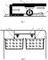
- the FIG.1 illustrates a diagram of a utility vehicle 1 seen on the side intended to make frequent deliveries, according to an exemplary embodiment of the invention.
- the vehicle comprises a cabin 2 and a load volume 3 for receiving boxes, this volume being of parallelepiped shape.
- the cabin 2 and the loading volume 3 are separated by a wall 4.
- the boxes may be foodstuffs for which the cold chain must be respected.
- the utility vehicle is equipped with at least one thermally insulated compartment.
- the vehicle can be equipped with 3 types of compartments for example: one at room temperature, another maintained at a cool temperature (2 to 4 ° C), and a third at a freezing temperature (-20 ° C), the last two temperatures being maintained in small volumes closed by isothermal doors.
- a handler brings the vehicle in reverse in the immediate vicinity of a loading dock and / or delivery 5, and pushes from the dock in the vehicle the boxes stacked on trolleys with wheels.
- a trolley consists of a rectangular tray surmounted by casters pivotally mounted on an axis, qualified in this as “crazy”.
- a sliding stop called “shuttle” previously positioned at the rear of the vehicle slides between two guide rails provided for this purpose.
- This shuttle is schematically like an L-shaped piece, the horizontal leg being held between the two guide rails and the vertical leg, which protrudes above the guide rails, abuts against the tray of a trolley with wheels or a crate placed on it.
- a strap 7 is attached to the shuttle to allow an operator to bring it back to the rear opening of the vehicle.
- At least one horizontal bar 8, called “roof bar” is fixed under the roof of the vehicle inside.
- This roof bar holds the crates at the top of the stacks, and prevents them from tipping during transport.
- the height of the roof bar 8 is calculated so that a maximum number of stacked boxes pass under this bar and the outcrop.
- the space between the top of the highest box and the lower face of the bar 8 is of the order of one centimeter.
- the roof bar is positioned to be vertical to the segment cutting the middle of the box below, the positioning of the box being provided by a guide means present at the floor of the load volume.
- the crates are stacked on top of each other on a cart, and the stacks are aligned and loaded from the rear of the vehicle.
- the load volume has more than one queue of crates accessible from the opening, then an equal number of bars 8 can be attached to the roof.
- the stacks are held by a plurality of anti-roll bars 9 plated on the side walls, left and right of the volume 3 loading.
- the roof bar does not cover the entire length of the load volume. At a location whose length is approximately equal to that of a box, the bar stops, allowing the operator to tilt the stack of boxes and extract them easily. If a stack is to be placed there, then the crates are maintained by conventional means of securement. By pushing them, the crates leave this place and position themselves under the roof bar.
- the Fig. 2 shows a stack of boxes 11 loaded at the rear of a utility vehicle, the boxes being placed on trolleys with wheels 10 and loaded by the rear opening of the vehicle. A minimum distance is left between the rear of the vehicle 1 and the edge of the loading dock 5.
- the operator positions a boarding ramp 12 to extend the floor of the cargo volume 3 to the dock.
- This ramp which we will see details later, is a substantially flat plate which is stored in a space arranged between the anti-roll bars 9 and the vehicle wall. The ramp extends the tracks in the vehicle to the rear.
- a maximum height typically 1.80 meters, this height being defined by the internal dimensions of the vehicle. If a single carriage is not sufficient, the operator can stack the boxes 11 on several carriages to form queues, for example two rows of four trolleys with casters each supporting five boxes.
- the trolley By pushing a stack of crates into the vehicle, the trolley comes into contact with the vertical branch of the shuttle and pushes it towards the front of the vehicle. When the operator wants to unload the boxes through the rear opening of the vehicle, it is sufficient to pull the strap 7 to bring back the shuttle and the stack of boxes.
- the Fig. 3 represents a diagram of a loading volume seen from above, showing the elements fixed on the ground.
- the loading volume comprises a so-called “ambient” compartment 20 intended to contain two rows of boxes stacked on carts and another compartment 21 called “fresh” containing a single line of boxes placed in a refrigerated environment. Closing the compartments is done by closing the rear door of the vehicle (not shown). One of the two doors having an insulated panel for thermally isolating the cold compartment 21.
- the Fig. 3 shows four carriages 10 arranged in different places.
- the casters of the carriages engage in a running rail 22 formed by two rectilinear profiles a few centimeters high and extending along the length of the compartment. Since the rollers are pivotally mounted on one axis, the running rail 22 guides the carriages 10 in a straight line and precisely positions them in the compartments of the loading space 3.
- a single running rail 22 is installed by line trolleys in the ambient compartment. The wheels on the side that does not have rails do not need to be guided. In this way, the compartment has a minimum number of elements on the ground which limits obstacles and facilitates the movement of an operator and lightens the structure to increase the loading capacity.
- the ambient compartment has two rails 22 associated with two rows of carriages. Looking at the vehicle from the rear, the rolling track on the left guides the right wheels of the carts in the left lane and the rail on the right guides the left wheels of the trolleys in the right lane.
- the Fig. 3 shows the carriage 10a in the left queue and the carriage 10b in the right line.
- the two rails can also guide trolleys forming a third line of trolleys positioned astride the first and second lines, the trolley 10c is positioned on the third line.
- the right and left wheels of the carriages positioned on this third file abut against one of the rectilinear profiles constituting the rails 22 of the right and left files.
- the left wheels are guided by the left rail profile of the left file, and the right wheels are guided by the right profile of the track of the straight line.
- Other arrangements are possible, for example, one where the positioning of the rails allows the wheels of the carriages of the third file roll in the rails 22 and not side. As we will see later, this third file is intended to receive trolleys on which empty boxes are stacked.
- Each line of trolleys has its shuttle 6 sliding in its groove 23.
- the grooves 23 are shorter than the running rails 22 because the shuttle normally moves from the opening to a distance from the opening of the opening the vehicle equals the width of a cart.
- a gear reduction system 26 based on pulleys is set up at the level of the strap 7.
- a locking system 25 positioned on the axis of each groove 23 and close the opening of the vehicle, keeps the strap 7 in tension and thus keep the shuttle in contact with a carriage during transport, so as to block the queue of carriages.
- This locking system 25 is for example a narrowing between two parts to jam the strap, a hook or a cleat.
- the part of the strap located after the locking means is free and can advantageously be stored in a box on the side of the vehicle.
- the shuttle 6 is more or less close to the opening.
- the operator places the last carriage 10 as close to the closed door against a fixed stop, this fixed stop being removable during unloading at the dock. In this way, the movements of the queues of trolleys are limited at the front by the shuttle and at the rear by said removable stop.
- the ramp 12 for extending the floor of the vehicle to the loading dock has a means for guiding the wheels of the carriages 10.
- Rectangular structures 27 are fixed on the ramp to create elevations whose flanks come into contact with the casters and can thus guide them.
- the two opposite sides of the rectangle have a slightly smaller spacing than the wheels of the carriages.
- At least one of the sides is in the extension of the profile of a rail 22 when the ramp is positioned at the rear of the vehicle. In this way, the operator rolls the trolley surmounted by boxes on the ramp so that his rollers are placed on each side of the structure 27. Once this positioning is done, the operator continues to push the stack of boxes towards the top of the box.
- the profile of the rear-facing structure is no longer rectangular but beveled.
- a single wheel first comes into contact with the structure and follows its beveled profile, then continuing to advance, the wheel on the other side comes into contact with the other side of the structure. In this way, a misalignment of the carriage at loading can be corrected naturally when it advances on the ramp and in the load volume.
- the fresh compartment 21 is an isothermal box having walls 28 with a thickness of at least 5 centimeters. This thickness also exists at the level of the floor, so that the floor of this compartment is at least 5 centimeters above that of the floor of the ambient compartment. To avoid the operator to provide a major effort to hoist a carriage carrying crates, the portion of the ramp 12 facing the fresh compartment is inclined differently from the portion of the ramp facing the ambient compartment. The boundary between these two parts is represented by the dotted line 28 visible on the Fig. 3 .
- the Fig. 4 shows the ramp 12 profile view and the detail of the two slopes.
- the ramp has a first platform 30, one side of which rests on the loading dock 5 and the opposite side on the floor 31 of the fresh compartment.
- the ramp also has a second platform 32, one side of which rests on the embarkation platform 5 and the opposite side on the floor 33 of the ambient compartment.
- the ramp is preferably made of thick plate, each platform 30 and 32 is substantially rectangular and their connection (materialized by the line 29) is typically triangular. The difference in inclination of these two parts depends on the thickness of the isothermal wall, and the length of the ramp.
- the ramp co-operates with the rear of the vehicle to position itself so that the structures 27 are situated in the extension of the running rails 22.
- the other side of the ramp lands on the platform 5 on a surface allowing defects to occur. alignment of the vehicle with the dock.
- the Fig. 5 shows the details of a ramp seen from above according to an exemplary embodiment.
- Oblong slots 50 are dug in the sheet to form handles, these handles are located on the side that lands on the dock.
- the profiles 27 for guiding the wheels of the trolleys are straight angles welded directly to the ramp, each trolley line having a single profile for guiding either the right rollers or the left wheels of the carriage.
- the figure shows the two platforms 30 and 31 separated by a triangular connection 29 ensuring their mechanical connection.
- the Fig. 6 shows the details of a ramp viewed in perspective according to the same embodiment.
- a raised edge 51 is disposed on each side of the ramp to prevent the fall of the trolleys on the sides.
- the Fig. 7 shows a detail of the shuttle and its cooperation with the trolleys on wheels.
- the shuttle 6 slides in the groove 21 seen by transparency, and the carriage 10 rolls on the floor 34 of the compartment.
- the vertical branch 35 of the shuttle abuts with the edge of the plate 36 of the carriage.
- the assembly formed by the shuttle and the trolleys then moves in the direction of arrows.
- the Fig. 8 shows the details of the anti-roll bars and roof bars intended to block the crates stored in the ambient compartment.
- the exemplary embodiment illustrated by the Fig. 8 shows two rows of stacked boxes, placed on trolleys 10 rolling in the rails 22.
- the boxes used have a lid that folds to form a surface to support the box above.
- the hinges of the lid protrude in height from the lid and form a longitudinal spar extending over the length of the box. This spar is profiled to also be used by the lateral locking system.
- the anti-roll bars 9 are fixed to the left of the left file and to the right of the right file on the walls of the compartment.
- the anti-roll bars consist of lips extending downwards and coming to hook the spar of boxes located at a certain level. It is useless to maintain all the boxes, in the example, the boxes of the second level and the fourth level are maintained by anti-roll bars.
- the anti-roll bars extend over the length of the compartment.
- the free space between the crate at the top of the stack and the roof of the vehicle is used for storing carts.
- Flat transport bars 30 are arranged above the rows of carriages and spaced a distance smaller than those of the width of a carriage and greater than that between the wheels of said tray.
- the transport bars 30 which can accommodate as many carriages as the files below have stops located at the front and rear ends that hold the carts during transport. The operator extracts the carriages either from behind or from the front, slightly lifting the carriages to release them from said stops.
- the middle transport bars 30 are hung from the ceiling by a vertical support which extends downwards for fixing the roof bar 8.
- the roof bar is placed in the middle of the ambient compartment and is fixed at a height to block the crates stacked on the third file, the one that straddles the right file and the left file of this compartment.
- this file is intended to contain the empty boxes stacked into each other.
- the height between the roof bar and the floor is calculated to be greater than one centimeter of a total including the height of a carriage and a number of stacked crates. In the embodiment carried out, it is possible to stack 18 empty boxes under the roof bar.
- transport bars 30 can store a single queue of carts above the third file.
- the transport bars 30 are hung on the ceiling by two vertical supports which extend downwards for the fixing of two roof bars 8.
- the two roof bars 8 are positioned above the right and left files trolleys and ensure the blocking of crates on these two lines.
- the height separating these roof bars and the floor is calculated to be greater than one centimeter of a total including the height of a carriage and a number of stacked full boxes. In the embodiment made, one can stack 5 boxes full on each other.
- the roof bar 8 is mounted on at least 2 articulated links, the bar is lowered and is set in position with the vehicle door closure.
- the bar 8 may be rack type to support a pawl installed on the retaining structure of the first stack.
- the fresh compartment is of a height lower than that of the ambient compartment. This difference in height is put to good use by installing a drawer above the fresh compartment. This drawer allows storage of bags and small items.
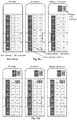
- the sample procedure includes the steps illustrated by the Fig. 10 .a, 10.b, 10.c 10.d and 10.e.
- the cabin housing the driver is surmounted by a housing accessible from the loading volume and in particular the ambient compartment.
- the vehicle has a door on the side allowing lateral access to the ambient compartment.
- Each figure illustrates three moments of a delivery, these moments being represented by the states of the boxes in the compartment.
- the image on the left represents the state on arrival of a delivery
- the image in the center represents the state of the crates after the operator has extracted the ones to be delivered.
- the figure on the right represents the state after recovery by the operator of empty boxes and just before departure for the next delivery.
- Empty boxes from the ambient compartment are nested one inside the other and can constitute a stack of 17 boxes.
- 17 boxes stacked and nested on a carriage are a height slightly less than the height of the roof bar 8 which blocks the stack during transport and prevents tipping in one direction or another. Empty boxes coming from the fresh compartment can not fit into each other.
- the position of the boxes represented by the image on the right shows an optimal disposition in terms of maintenance, this state ensures that during transport, crates will not tilt.
- step 10.a the vehicle 1 is filled with a maximum of boxes.
- the ambient compartment has two rows of six carriages, each carriage supporting a stack of five boxes. 60 cases are therefore contained in the ambient compartment.
- the fresh compartment has a row of 6 trolleys, each trolley supporting a stack of 4 boxes. 24 crates are therefore contained in the fresh compartment.
- step 10.a the contents of a box of the fresh compartment and the contents of four boxes of the ambient compartment are delivered, the contents of the boxes located in the right queue are delivered first.
- the five empty crates are stored in the housing above the driver by passing through the side door.
- step 10.b the operator has delivered a number of cash contents and has advanced the length of a carriage the right file of the ambient compartment. The space thus released at the front of this queue makes it possible to store 3 empty boxes.
- step 10.b the contents of a box of the fresh compartment and the contents of two boxes of the ambient compartment are delivered.
- step 10.a the two empty boxes are arranged at the front of the right line by passing through the side door.
- step 10.c the operator delivered a number of cash contents and advanced the three queues of the length of a cart.
- the square thus released at the front of the two files can store 10 empty boxes. 8 of these empty boxes are stacked on the third row of the ambient compartment. These 8 empty boxes are wedged by the two rows of full boxes.
- step 10.b the contents of three crates of the ambient compartment are delivered, and the straight file has advanced the length of a carriage.
- step 10.a the three empty crates are arranged at the front of the third file by passing through the side door.
- step 10.d the right and left files of the ambient compartment advanced two carts in length. The place thus released at the front of the two files makes it possible to store two stacks of empty boxes on the third file of the ambient compartment. These two stacks of empty crates are wedged by the two rows of full crates.
- step 10.d the contents of two crates of the fresh compartment and the contents of five crates of the ambient compartment are delivered. The contents of the crates of the ambient compartment are extracted from the right and left queues and the straight line has advanced the length of a trolley.
- the five empty crates are arranged at the front of the third line by passing through the side door. The two stacks of empty crates are wedged by the left file, thus avoiding unwanted tilts.
- step 10.e the right and left files of the ambient compartment advanced three carts in length.
- the space thus released at the front of the two files makes it possible to store three stacks of empty boxes on the third file of the ambient compartment.
- Stacking only concerns crates from the fresh compartment. Another stack reaches the maximum size, this stack is notably blocked by the roof bar.
- These three stacks of empty boxes are wedged by the left file of full boxes.
- step 10.e the contents of two crates of the fresh compartment and the contents three cases of the ambient compartment are delivered.
- the three empty crates are arranged at the front on the second stack of the third file.
- the operator therefore has a buffer zone that allows one hand to store empty boxes and secondly, to sort the crates for the cool and crates for the environment.
- the crates for the fresh are blue and the crates for the environment are green.
- the Figures 10.a to 10.e illustrate an unloading process where the stacks of crates are extracted from the rear of the vehicle upon delivery and empty crates are placed at the front of the vehicle by the side doors. In this way the driver never goes into the vehicle which facilitates its delivery.
- the vehicle On departure the vehicle consists of a set of stacks of full boxes loaded from a dock and automatically maintained during transport. When returning from tour, the vehicle consists of a set of empty stacks held during transport and can be easily discharged from a dock.
- the useful load volume is divided into a plurality of compartments.
- the utility vehicle 1 is equipped with 3 types of compartments placed at different temperatures: a compartment 40 maintained at a freezing temperature (-20 ° C), a compartment 41 maintained at a cool temperature (2 to 4 ° C), and the remainder 42 of the loading volume set to room temperature, and optionally refrigerated slightly (for example 15 ° C).
- the compartment 40 is surrounded by a reinforced thermal insulation (for example a foam thickness of 60 millimeters) and a high performance isothermal door. It is arranged transversely and accessible by the sliding side door 45 of the vehicle.
- the cold generator is placed above this compartment and against the partition wall between the cabin and the loading area.
- a free volume is left above the freezer compartment 40 to store fruit cartons and vegetables for example, or carts or empty crates.
- the compartment 41 is also surrounded by a thermal insulation and provided with an isothermal door which opens, preferably, at the same time as the door of the vehicle. This provision compartments allows fast loading and unloading crates, because of the access from the back of the bulk of the cargo. Narrow housing and reaching the height are available at the passage of the wheel 43. These housing can accommodate the empty carts 17 and / or the ramp 12.
Landscapes
- Engineering & Computer Science (AREA)
- Mechanical Engineering (AREA)
- Transportation (AREA)
- Handcart (AREA)
- Fittings On The Vehicle Exterior For Carrying Loads, And Devices For Holding Or Mounting Articles (AREA)
- Warehouses Or Storage Devices (AREA)
Description
L'invention concerne un dispositif pour charger et décharger des caisses d'un fourgon. L'invention s'applique notamment dans le cas où les caisses sont destinées à être livrées à domicile par un manutentionnaire.The invention relates to a device for loading and unloading crates of a van. The invention is particularly applicable in cases where the crates are intended to be delivered home by a handler.
De nombreux véhicules utilitaires permettent le transport de marchandises. Ces véhicules comportent une cabine pour le pilotage et un volume de chargement. L'accès à ce volume de chargement s'effectue par le coté, généralement par une porte coulissante, ou par l'arrière. Le volume de chargement est accessible par une porte rideau ou, une ou deux portes pivotantes, soit à l'arrière, soit sur le coté. Généralement, la largeur intérieure de la porte est quasiment égale à celle de l'intérieur du volume de chargement. De cette façon, il est possible de charger des colis volumineux à l'aide d'un chariot élévateur, en les montant à la hauteur du plancher, puis un manutentionnaire pousse les colis dans le volume de chargement en commençant par le fond, c'est à dire le plus près possible de la cabine. Pour faciliter l'opération, des chariots sont parfois utilisés pour charger le véhicule à partir d'un quai d'entrepôt.Many commercial vehicles allow the transport of goods. These vehicles include a cabin for piloting and a loading volume. Access to this loading volume is effected by the side, usually by a sliding door, or from the rear. The loading volume is accessible through a curtain door or one or two pivoting doors, either at the rear or on the side. Generally, the interior width of the door is almost equal to that of the interior of the load volume. In this way, it is possible to load bulky packages with a forklift, by mounting them at floor height, then a handler pushes the packages in the load volume starting from the bottom, it is as close as possible to the cabin. To facilitate the operation, trolleys are sometimes used to load the vehicle from a warehouse dock.
Des véhicules isothermes sont employés pour transporter des produits frais. Pour cela, certains véhicules utilitaires sont dotés de plusieurs compartiments permettant de transporter des denrées alimentaires à des températures différentes. Dans ce cas, des compartiments spécifiques fermés par des portes isothermes sont aménagés dans le volume de chargement. Généralement, les compartiments à basse température destinés à transporter des denrées congelées ont une petite capacité. Le volume de chargement accessible directement par la porte extérieure peut être maintenu à une température fraiche, pour le transport des légumes et des fruits par exemple.Isothermal vehicles are used to transport fresh produce. For this, some commercial vehicles have several compartments for transporting food at different temperatures. In this case, specific compartments closed by insulated doors are arranged in the load volume. Generally, low temperature compartments for transporting frozen food have a small capacity. The load volume accessible directly from the outside door can be maintained at a cool temperature, for transporting vegetables and fruits for example.
Dans de tels véhicules, il est important de laisser ouverte la porte le moins longtemps possible de façon à ne pas modifier la température intérieure. Pour cela, le chargement est préparé sur le quai d'embarquement et le véhicule est approché à proximité immédiate de celui-ci de façon qu'un manutentionnaire transporte des groupes de colis à l'aide d'un chariot élévateur, de chariots ou de palettes dotées de roues. Le quai d'embarquement est aménagé pour être quasiment à la même hauteur que le plancher du véhicule. Selon une variante, le plancher du véhicule comporte des rouleaux disposés transversalement au véhicule. Un manutentionnaire présente l'ouverture du véhicule à proximité du quai d'embarquement, et pousse les colis sur les rouleaux. Dans tous les cas, le chargement peut s'effectuer en poussant l'ensemble des colis du quai vers le volume de chargement.In such vehicles, it is important to leave the door open long time possible so as not to change the indoor temperature. For this, the load is prepared on the embarkation platform and the vehicle is approached in the immediate vicinity thereof so that a handler transports groups of packages using a forklift, trolleys or trucks. pallets with wheels. The loading dock is designed to be almost at the same height as the floor of the vehicle. According to one variant, the floor of the vehicle comprises rollers arranged transversely to the vehicle. A handler presents the opening of the vehicle near the loading dock, and pushes the packages on the rollers. In all cases, the loading can be carried out by pushing all the packages from the platform to the loading volume.
Pour faciliter la livraison et limiter le temps d'ouverture de la porte extérieure, les colis à livrer en dernier sont ceux placés contre la cabine, et ceux à livrer en premier sont placés en dernier, tout près de la porte. Les premiers colis sont facilement préhensibles par le manutentionnaire à l'extérieur du véhicule. Mais les derniers nécessitent d'aller les chercher au fond et donc de s'introduire dans le volume de chargement. Lors de la livraison, le manutentionnaire n'est pas sur un quai et se trouve souvent devant le domicile d'un particulier. Il doit donc enjamber la hauteur entre le sol et le plancher, et une fois à l'intérieur, déplacer les colis du fond vers l'ouverture, descendre du véhicule et prendre un à un les colis pour les placer sur un chariot mobile et les apporter à leurs destinataires. Ces opérations sont longues, répétitives, et perturbe la température qui doit rester constante dans le volume de chargement. De plus, ces manutentions génèrent de la fatigue physique et peuvent provoquer des troubles musculeux-squelettiques.To facilitate delivery and limit the opening time of the outer door, the packages to be delivered last are those placed against the cab, and those to be delivered first are placed last, close to the door. The first packages are easily prehensile by the handler outside the vehicle. But the last need to go to the bottom and therefore to get into the load volume. During delivery, the handler is not on a dock and is often in front of an individual's home. It must therefore span the height between the ground and the floor, and once inside, move the packages from the bottom to the opening, get off the vehicle and take the packages one by one to place them on a mobile cart and bring to their recipients. These operations are long, repetitive, and disturb the temperature which must remain constant in the load volume. In addition, these operations generate physical fatigue and can cause muscular-skeletal disorders.
De plus, si les colis ne sont pas bien calés, ils peuvent bouger et tomber dans le véhicule, et occasionner des casses de produits. Lorsque des empilements de colis sont supprimés au fur et à mesure des livraisons, des espaces libres se dégagent et les colis peuvent bringuebaler au cours du transport, s'ils ne sont pas arrimés. Pour les livraisons à domicile, le temps est très réduit et les livreurs n'ont pas le temps d'arrimer les colis. C'est pourquoi des casses de produits interviennent fréquemment.In addition, if the packages are not well set, they can move and fall into the vehicle, and cause breakage of products. When stacks of parcels are removed as and when deliveries, free spaces emerge and packages can bringuebaler during transport, if they are not stowed. For home deliveries, the time is very short and the delivery men do not have time to secure the packages. This is why breakages of products occur frequently.
Le document
Le document
Le document
Le document
Le document
La présente invention propose un dispositif facilitant le déchargement des colis d'un véhicule utilitaire en diminuant les efforts musculaires fournis par un manutentionnaire et tout en diminuant le temps de déchargement. De plus, la présente invention permet aussi de maintenir les caisses au cours du transport.The present invention proposes a device facilitating the unloading of parcels of a commercial vehicle by reducing the muscular efforts provided by a handler and while decreasing the unloading time. In addition, the present invention also makes it possible to maintain the crates during transport.
La présente invention propose un nouveau moyen pour décharger des colis entre le volume de chargement d'un véhicule et un quai d'embarquement et/ou de livraison.The present invention proposes a new means for unloading packages between the loading volume of a vehicle and a loading and / or delivery platform.
A cet effet, l'invention concerne un véhicule destiné à transporter des caisses dans un volume de chargement, lesdits caisses étant empilées sur au moins un chariot à roulettes coopérant avec au moins un rail de roulement fixé sur le plancher pour guider le déplacement dudit chariot, le véhicule comportant au moins un dispositif exerçant une force horizontale sur une file de caisses posées sur au moins un chariot pour les déplacer vers une ouverture du véhicule. Le véhicule comporte en outre au moins une barre de toit maintenant en partie supérieure au moins un empilement de caisses posées sur un chariot.For this purpose, the invention relates to a vehicle for transporting crates in a loading space, said crates being stacked on at least one trolley with wheels cooperating with at least one rail mounted on the floor to guide the movement of said trolley , the vehicle comprising at least one device exerting a horizontal force on a line of boxes placed on at least one carriage to move them to an opening of the vehicle. The vehicle further comprises at least one roof bar now in the upper part at least one stack of boxes on a carriage.
De cette manière, le déchargement du volume de chargement est facilité, la livraison est rapide et demande moins d'efforts physiques au manutentionnaire. De plus, la structure assure un bon maintien des caisses dans le volume de chargement, évitant ainsi de la casse au cours du transport.In this way, the unloading of the loading volume is facilitated, the delivery is fast and requires less physical effort to the handler. In addition, the structure ensures a good maintenance of the crates in the load volume, thus avoiding breakage during transport.
Selon un premier mode de réalisation, la barre de toit est destinée à bloquer un empilement de caisses vides et emboitées les unes dans les autres, la distance entre le plancher du véhicule et ladite barre de toit étant légèrement supérieure à la somme des hauteurs d'un chariot et d'un nombre déterminé de caisses vides et emboitées les unes dans les autres.According to a first embodiment, the roof bar is intended to block a stack of empty boxes and nested in each other, the distance between the floor of the vehicle and said roof bar being slightly greater than the sum of the heights of a trolley and a fixed number of empty boxes and nested one inside the other.
Selon un autre mode de réalisation, la barre de toit est destinée à bloquer un empilement de caisses posées les unes sur les autres avec le couvercle refermé, la distance entre le plancher du véhicule et ladite barre de toit étant légèrement supérieure à la somme des hauteurs d'un chariot et d'un nombre déterminé de caisses posées les unes sur les autres avec le couvercle refermé.According to another embodiment, the roof bar is intended to block a stack of crates placed on one another with the cover closed, the distance between the floor of the vehicle and said roof bar being slightly greater than the sum of the heights of a carriage and a fixed number of crates placed on top of each other with the cover closed.
Selon l'invention, le véhicule comporte au moins une barre anti-devers fixée horizontalement sur la longueur d'au moins une paroi intérieure du volume de chargement, les caisses présentant au moins un longeron longitudinal s'étendant sur le coté et le dessus, la barre anti-devers venant crocheter ledit longeron par le dessus.According to the invention, the vehicle comprises at least one anti-roll bar fixed horizontally along the length of at least one inner wall of the loading space, the boxes having at least one longitudinal spar extending on the side and the top, the anti-roll bar hooking said spar from above.
Selon un autre mode de réalisation, la barre anti-devers crochète des caisses posées les unes sur les autres avec le couvercle refermé, la hauteur de la barre anti-devers se situant à une hauteur égale à la somme des hauteurs d'un chariot et d'un nombre déterminé de caisses posées les unes sur les autres avec le couvercle refermé.According to another embodiment, the anti-roll bar hooks crates placed on one another with the lid closed, the height of the anti-roll bar being at a height equal to the sum of the heights of a carriage and a fixed number of crates placed on each other with the cover closed.
Selon un autre mode de réalisation, le dispositif exerçant une force horizontale sur une file de caisses posées sur au moins un chariot est une butée mobile glissant dans un rail de guidage fixé au plancher du volume de chargement et venant en contact avec un chariot ou une caisse posée dessus, ladite butée mobile se déplaçant au moyen d'une sangle vers l'ouverture du véhicule.According to another embodiment, the device exerting a horizontal force on a line of boxes placed on at least one carriage is a sliding stop sliding in a guide rail fixed to the floor of the loading space and coming into contact with a carriage or a carriage. body lying on top, said movable stop moving by means of a strap towards the opening of the vehicle.
Selon un autre mode de réalisation, le véhicule comporte des éléments de blocage de ladite sangle à proximité de l'ouverture, afin de maintenir en tension la sangle selon une direction longitudinale au véhicule lorsque ladite butée mobile vient en contact sur un chariot ou une caisse posée dessus qui vient lui-même buter contre une butée fixe présente à proximité de l'ouverture du véhicule.According to another embodiment, the vehicle comprises locking elements of said strap close to the opening, in order to keep the strap in tension in a longitudinal direction to the vehicle when said movable stop comes into contact on a carriage or a body placed on it which comes abut against a fixed stop present near the opening of the vehicle.
Selon un autre mode de réalisation, le volume de chargement comporte au moins deux rails de roulement destinés à guider les roulettes soit gauches soit droites de deux files de chariots.According to another embodiment, the loading volume comprises at least two rails for guiding the wheels either left or straight of two rows of carriages.
Selon un autre mode de réalisation, le véhicule comporte une rampe d'accès se posant à l'arrière du véhicule afin de prolonger le plancher jusqu'au quai de chargement, la dite rampe d'accès comportant des éléments droits prolongeant les rails de roulement présents dans le volume de chargement.According to another embodiment, the vehicle comprises an access ramp at the rear of the vehicle to extend the floor to the loading dock, said access ramp having straight elements extending the rails present in the load volume.
Selon un autre mode de réalisation, le volume de chargement comporte deux parties ayant des planchers à des hauteurs différentes, ladite rampe d'accès étant constituée de deux plateformes, chacune venant se poser sur chaque plancher des deux parties du volume de chargement et se prolongeant pour se poser sur le quai de chargement, les deux plateformes ayant des pentes différentes pour compenser la différence de hauteur des planchers.According to another embodiment, the loading volume comprises two parts having floors at different heights, said access ramp consisting of two platforms, each coming to rest on each floor of the two parts of the cargo volume and extending to land on the loading dock, the two platforms having different slopes to compensate for the difference in height of the floors.
Selon un autre mode de réalisation, le véhicule comporte un compartiment ambiant contenant une pluralité de files de caisses, un compartiment frais contenant une seule file de caisses, le dit compartiment frais ayant une hauteur inférieure à la hauteur du compartiment ambiant, et un tiroir placé au dessus du compartiment frais dont le contenu est accessible en le tirant vers l'arrière du véhicule.According to another embodiment, the vehicle comprises an ambient compartment containing a plurality of queues of cases, a fresh compartment containing a single line of boxes, said fresh compartment having a height less than the height of the ambient compartment, and a drawer placed above the fresh compartment whose contents are accessible by pulling it towards the rear of the vehicle.
Selon un autre aspect, l'invention concerne un procédé de déchargement d'un véhicule qui est décrit selon l'un des paragraphes précédent et qui comporte une porte arrière donnant accès à l'arrière des files de caisses et une porte latérale donnant accès à l'avant des files de caisses. Le procédé consiste à décharger au moins un empilement de caisses pleines par l'arrière du véhicule, à déplacer au moins une file de caisses vers l'arrière d'au moins la longueur d'un empilement et d'introduire des caisses vides par la porte latérale pour les placer à l'emplacement ainsi libéré à l'avant de la file déplacée.According to another aspect, the invention relates to a method of unloading a vehicle which is described according to one of the preceding paragraphs and which comprises a rear door giving access to the rear of the queues of boxes and a side door giving access to the front of the crates. The method comprises unloading at least one stack of full boxes from the rear of the vehicle, moving at least one queue of boxes rearward at least the length of a stack and introducing empty boxes by the side door to place them at the location thus released at the front of the moved file.
Selon un autre mode de réalisation, les caisses vides sont emboitées les unes dans les autres formant un empilement ayant un nombre de caisses au moins égal au double du nombre de caisses pleines dans un empilement. La file de caisses vides se place à cheval sur les rails de roulement de deux files de caisses pleines et les empilements de caisses vides sont maintenus par la barre de toit.According to another embodiment, the empty boxes are nested in each other forming a stack having a number of boxes at least equal to twice the number of full boxes in a stack. The line of empty boxes straddles the running rails of two rows of full crates and the stacks of empty crates are held by the roof bar.
D'autres caractéristiques et avantages de l'invention apparaîtront maintenant avec plus de détails dans le cadre de la description qui suit d'exemples de réalisation donnés à titre illustratif et non-limitatif en se référant aux figures annexées qui représentent :
- la
figure 1 présente un schéma d'un véhicule utilitaire vu de profil selon un exemple de réalisation, - la
figure 2 montre un empilement de caisses chargées à l'arrière d'un véhicule de type utilitaire, selon un exemple de réalisation, - la
figure 3 représente un schéma d'un volume de chargement vu du dessus, en montrant les éléments fixés sur le sol, - la
figure 4 montre les détails d'une rampe vue de profil, ladite rampe étant dotée d'une double pente, - la
figure 5 montre les détails d'une rampe vue du dessus selon un exemple de réalisation, - la
figure 6 montre les détails d'une rampe vue en perspective selon le même exemple de réalisation, - la
figure 7 montre un détail de la navette et sa coopération avec les chariots à roulettes, - la
figure 8 montre les détails des barres anti-devers et des barres de toit destinées à bloquer les caisses posées sur les chariots - la
figure 9 montre une variante d'implémentation des barres de transport et des deux barres de toit, - Les
figures 10.a, 10.b ,10.c 10.d et10.e . décrivent le contenu d'un véhicule au cours d'un déchargement, illustrant les étapes d'une procédure de déchargement, - la
figure 11 montre l'organisation des différents compartiments du volume de chargement selon un exemple de réalisation.
- the
figure 1 shows a diagram of a utility vehicle seen in profile according to an exemplary embodiment, - the
figure 2 shows a stack of crates loaded at the rear of a utility vehicle, according to an exemplary embodiment, - the
figure 3 represents a diagram of a loading volume seen from above, showing the elements fixed on the ground, - the
figure 4 shows the details of a ramp seen in profile, said ramp having a double slope, - the
figure 5 shows the details of a ramp seen from above according to an exemplary embodiment, - the
figure 6 shows the details of a ramp viewed in perspective according to the same embodiment, - the
figure 7 shows a detail of the shuttle and its cooperation with the trolleys with wheels, - the
figure 8 shows the details of anti-roll bars and roof bars designed to block crates on carts - the
figure 9 shows an alternative implementation of the transport bars and the two roof bars, - The
Figures 10.a, 10.b ,10.c 10.d and10.e . describe the contents of a vehicle during unloading, illustrating the steps of an unloading procedure, - the
figure 11 shows the organization of the different compartments of the loading volume according to an exemplary embodiment.
L'invention concerne un véhicule destiné à transporter des caisses dans un volume de chargement, lesdits caisses étant empilées sur au moins un chariot à roulettes coopérant avec au moins un rail de roulement fixé sur le plancher pour guider le déplacement dudit chariot, le véhicule comportant au moins un dispositif exerçant une force horizontale sur une file de caisses posées sur au moins un chariot pour les déplacer vers une ouverture du véhicule. Le véhicule comporte en outre au moins une barre de toit maintenant en partie supérieure au moins un empilement de caisses posées sur un chariot. La présence d'une barre de toit assure un bon maintien des caisses dans le volume de chargement, évitant ainsi de la casse au cours du transport.The invention relates to a vehicle for transporting crates in a loading volume, said crates being stacked on at least one trolley with wheels cooperating with at least one rail mounted on the floor to guide the movement of said trolley, the vehicle comprising at least one device exerting a horizontal force on a line of boxes placed on at least one carriage to move them to an opening of the vehicle. The vehicle further comprises at least one roof bar now at least one upper part at least one stack of crates placed on a cart. The presence of a roof bar ensures a good maintenance of the crates in the cargo volume, thus avoiding breakage during transport.
La
Selon l'invention, un manutentionnaire amène le véhicule en marche arrière à proximité immédiate d'un quai d'embarquement et/ou de livraison 5, et pousse du quai dans le véhicule les caisses empilées sur des chariots à roulettes. Un tel chariot est constitué d'un plateau rectangulaire surmonté par des roulettes montées pivotantes sur un axe, qualifiées en cela de « folle ». Une butée coulissante appelée « navette » préalablement positionnée à l'arrière du véhicule glisse entre deux rails de guidage prévus à cet effet. Cette navette se présente schématiquement comme une pièce en L, la branche horizontale étant maintenue entre les deux rails de guidage et la branche verticale, qui dépasse au-dessus des rails de guidage, vient buter contre le plateau d'un chariot à roulettes ou une caisse posée dessus. Une sangle 7 est attachée à la navette pour permettre à un opérateur de ramener celle-ci vers l'ouverture arrière du véhicule.According to the invention, a handler brings the vehicle in reverse in the immediate vicinity of a loading dock and / or
Selon l'invention, au moins une barre horizontale 8, dite « barre de toit » est fixée sous le toit du véhicule à l'intérieur. Cette barre de toit maintient les caisses placées en haut des empilements, et les empêche de basculer lors du transport. La hauteur de la barre de toit 8 est calculée pour qu'un nombre maximum de caisses empilées passent sous cette barre et l'affleure. L'espace entre le dessus de la plus haute caisse et la face inférieure de la barre 8 est de l'ordre d'un centimètre. La barre de toit est positionnée de façon à être à la verticale du segment coupant le milieu de la caisse située en dessous, le positionnement de cette caisse étant assuré par un moyen de guidage présent au niveau du plancher du volume de chargement. Les caisses sont empilées les unes sur les autres sur un chariot, et les empilements sont alignés et chargés par l'arrière du véhicule. Si le volume de chargement comporte plus d'une file de caisses accessibles à partir de l'ouverture, alors un nombre égal de barres 8 peut être fixées au toit. Selon un autre perfectionnement, pour améliorer la stabilité des caisses lors du transport, les empilements sont maintenus par une pluralité de barres anti-devers 9 plaquées sur les cloisons latérales, à gauche et à droite du volume 3 de chargement. Avantageusement, la barre de toit ne couvre pas toute la longueur du volume de chargement. A un endroit dont la longueur est approximativement égale à celle d'une caisse, la barre s'interrompt permettant à l'opérateur de basculer l'empilement de caisses et de les extraire facilement. Si un empilement doit être placé à cet endroit, alors les caisses sont maintenues par des moyens classiques d'arrimage. En les poussant, les caisses quittent cet endroit et se positionnent sous la barre de toit.According to the invention, at least one
La
En poussant dans le véhicule un empilement de caisses, le chariot à roulettes vient en contact avec la branche verticale de la navette et la repousse vers l'avant du véhicule. Lorsque l'opérateur veut décharger les caisses par l'ouverture arrière du véhicule, il lui suffit de tirer sur la sangle 7 pour ramener vers l'arrière la navette et les empilements de caisses.By pushing a stack of crates into the vehicle, the trolley comes into contact with the vertical branch of the shuttle and pushes it towards the front of the vehicle. When the operator wants to unload the boxes through the rear opening of the vehicle, it is sufficient to pull the
La
La
Selon un exemple de réalisation, le compartiment ambiant dispose de deux rails de roulement 22 associés à deux files de chariots. En regardant le véhicule par l'arrière, le rail de roulement situé à gauche guide les roulettes droites des chariots de la file gauche et le rail situé à droite guide les roulettes gauches des chariot de la file droite. La
Chaque file de chariots dispose de sa navette 6 glissant dans sa rainure 23. Les rainures 23 sont plus courtes que les rails de roulement 22 car la navette se déplace normalement de l'ouverture jusqu'à une distance de l'ouverture de l'ouverture du véhicule égale à la largeur d'un chariot. Pour diminuer l'effort de traction exercé par l'opérateur, un système de démultiplication 26 à base de poulies est mis en place au niveau de la sangle 7. Un système de blocage 25 positionné sur l'axe de chaque rainure 23 et à proximité de l'ouverture du véhicule, permet de maintenir la sangle 7 en tension et ainsi de maintenir la navette en contact avec un chariot lors du transport, de façon à bloquer la file de chariots. Ce système de blocage 25 est par exemple un rétrécissement entre deux pièces pour y coincer la sangle, un crochet ou un taquet. La partie de la sangle se situant après le moyen de blocage est libre et peut avantageusement être rangée dans une boite sur le coté du véhicule. Selon le nombre de chariots à roulettes placés dans le volume de chargement, la navette 6 est plus ou moins proche de l'ouverture. En déplaçant vers l'arrière la navette par traction sur la sangle 7, l'opérateur place le dernier chariot 10 au plus près de la porte fermée contre une butée fixe, cette butée fixe étant amovible lors du déchargement à quai. De cette façon, les déplacements des files de chariots sont limités à l'avant par la navette et à l'arrière par la dite butée amovible.Each line of trolleys has its
Selon un perfectionnement, la rampe 12 permettant de prolonger le plancher du véhicule jusqu'au quai d'embarquement dispose d'un moyen de guidage des roulettes des chariots 10. Des structures rectangulaires 27 sont fixées sur la rampe pour créer des surélévations dont les flancs entrent en contact avec les roulettes et peuvent ainsi les guider. Les deux cotés opposés du rectangle ont un écartement légèrement moins important que celui des roulettes des chariots. L'un au moins des cotés se trouve dans le prolongement du profilé d'un rail de roulement 22 lorsque la rampe est bien positionnée à l'arrière du véhicule. De cette manière, l'opérateur fait rouler le chariot surmonté de caisses sur la rampe pour que ses roulettes se placent de chaque coté de la structure 27. Une fois ce positionnement effectué, l'opérateur continue à pousser l'empilement de caisses vers l'avant du véhicule et les roulettes avant du chariot s'engage naturellement dans le rail de roulement, soit à droite soit à gauche. Avantageusement, le profil de la structure orienté vers l'arrière n'est plus rectangulaire mais biseauté. Ainsi, une seule roulette entre d'abord en contact avec la structure et suit son profil biseauté, puis en continuant d'avancer, la roulette de l'autre coté vient en contact avec l'autre coté de la structure. De cette manière, un défaut de positionnement du chariot se présentant au chargement peut être corrigé naturellement lorsqu'il s'avance sur la rampe puis dans le volume de chargement.According to an improvement, the
Le compartiment frais 21 est un caisson isotherme ayant des parois 28 d'une épaisseur d'au moins 5 centimètres. Cette épaisseur existe également au niveau du plancher, de sorte que le plancher de ce compartiment se situe à au moins 5 centimètres au dessus de celui du plancher du compartiment ambiant. Pour éviter à l'opérateur de fournir un effort important pour hisser un chariot transportant des caisses, la partie de la rampe 12 face au compartiment frais est inclinée différemment de la partie de la rampe face au compartiment ambiant. La limite entre ces deux parties est représentée par le trait en pointillé 28 visible sur la
La
La
la
La
La
Selon un perfectionnement, l'espace libre entre la caisse en haut de l'empilement et le toit du véhicule est utilisé pour le stockage des chariots. Des barres de transport 30 plates sont disposées au dessus des files de chariots et espacées d'une distance inférieure à celles de la largeur d'un chariot et supérieure à celle entre les roues dudit plateau. Les barres de transport 30 qui peuvent accueillir autant de chariots que les files situées en dessous comportent des butées situées aux extrémités avant et arrière qui maintiennent les chariots au cours du transport. L'opérateur extrait les chariots soit par l'arrière, soit par l'avant, en soulevant légèrement les chariots pour les dégager desdites butées.According to an improvement, the free space between the crate at the top of the stack and the roof of the vehicle is used for storing carts. Flat transport bars 30 are arranged above the rows of carriages and spaced a distance smaller than those of the width of a carriage and greater than that between the wheels of said tray. The transport bars 30 which can accommodate as many carriages as the files below have stops located at the front and rear ends that hold the carts during transport. The operator extracts the carriages either from behind or from the front, slightly lifting the carriages to release them from said stops.
Les barres de transport 30 du milieu sont accrochées au plafond par un support vertical qui se prolonge vers le bas pour la fixation de la barre de toit 8. Dans le mode de réalisation illustré par la
Selon une variante de réalisation illustrée par la
Selon un perfectionnement, la barre de toit 8 est montée sur au moins 2 biellettes articulées, la barre s'abaisse et est mise en position avec la fermeture de porte du véhicule. La barre 8 peut être de type crémaillère pour servir d'appui à un cliquet installé sur la structure de retenue du premier empilement.According to an improvement, the
Selon un autre perfectionnement, le compartiment frais est d'une hauteur inférieure à celui du compartiment ambiant. Cette différence de hauteur est mise à profit par l'installation d'un tiroir au-dessus du compartiment frais. Ce tiroir permet le stockage de sacs et de petits objets.According to another improvement, the fresh compartment is of a height lower than that of the ambient compartment. This difference in height is put to good use by installing a drawer above the fresh compartment. This drawer allows storage of bags and small items.
Après avoir décrit les différents équipements du véhicule objet de l'invention, nous allons maintenir décrire un exemple de procédure de déchargement de caisses. L'exemple de procédure comporte les étapes illustrées par les
Selon cet exemple, la cabine abritant le conducteur est surmonté d'un logement accessible à partir du volume de chargement et notamment du compartiment ambiant. Selon cet exemple, le véhicule dispose d'une porte sur le coté permettant un accès latéral au compartiment ambiant.According to this example, the cabin housing the driver is surmounted by a housing accessible from the loading volume and in particular the ambient compartment. According to this example, the vehicle has a door on the side allowing lateral access to the ambient compartment.
Chaque figure illustre trois moments d'une livraison, ces moments étant représentés par les états des caisses dans le compartiment. L'image de gauche représente l'état à l'arrivée d'une livraison, l'image au centre représente l'état des caisses après que l'opérateur ait extrait celles destinées à être livrées. La figure de droite représente l'état après récupération par l'opérateur des caisses vides et juste avant le départ pour la livraison suivante. Les caisses vides provenant du compartiment ambiant sont emboitées les unes dans les autres et peuvent constituer un empilement de 17 caisses. 17 caisses empilées et emboitées sur un chariot constituent une hauteur légèrement inférieure à la hauteur de la barre de toit 8 ce qui bloque l'empilement lors du transport et évite son basculement dans une direction ou une autre. Les caisses vides provenant du compartiment frais ne peuvent s'emboiter les unes dans les autres. La position des caisses représentée par l'image de droite montre une disposition optimale en terme de maintien, cet état assure qu'au cours du transport, des caisses ne basculeront pas.Each figure illustrates three moments of a delivery, these moments being represented by the states of the boxes in the compartment. The image on the left represents the state on arrival of a delivery, the image in the center represents the state of the crates after the operator has extracted the ones to be delivered. The figure on the right represents the state after recovery by the operator of empty boxes and just before departure for the next delivery. Empty boxes from the ambient compartment are nested one inside the other and can constitute a stack of 17 boxes. 17 boxes stacked and nested on a carriage are a height slightly less than the height of the
Au début de l'étape 10.a, le véhicule 1 est rempli d'un maximum de caisses. Le compartiment ambiant comporte deux files de 6 chariots, chaque chariot supportant un empilage de 5 caisses. 60 caisses sont donc contenues dans le compartiment ambiant. Le compartiment frais comporte une file de 6 chariots, chaque chariot supportant un empilage de 4 caisses. 24 caisses sont donc contenues dans le compartiment frais. Lors de l'étape 10.a, le contenu d'une caisse du compartiment frais et les contenus de quatre caisses du compartiment ambiant sont livrés, les contenus des caisses situées dans la file droite sont prioritairement livrés. A la fin de l'étape 10.a, les cinq caisses vides sont rangées dans le logement au-dessus du conducteur en les passant par la porte latérale.At the beginning of step 10.a, the
Au début de l'étape 10.b, l'opérateur a livré un certain nombre de contenus de caisse et a avancé de la longueur d'un chariot la file droite du compartiment ambiant. La place ainsi libérée à l'avant de cette file permet de stocker 3 caisses vides. Lors de l'étape 10.b, le contenu d'une caisse du compartiment frais et les contenus de deux caisses du compartiment ambiant sont livrés. A la fin de l'étape 10.a, les deux caisses vides sont rangées à l'avant de la file droite en les passant par la porte latérale.At the beginning of step 10.b, the operator has delivered a number of cash contents and has advanced the length of a carriage the right file of the ambient compartment. The space thus released at the front of this queue makes it possible to store 3 empty boxes. In step 10.b, the contents of a box of the fresh compartment and the contents of two boxes of the ambient compartment are delivered. At the end of step 10.a, the two empty boxes are arranged at the front of the right line by passing through the side door.
Au début de l'étape 10.c, l'opérateur a livré un certain nombre de contenus de caisse et a avancé les trois files de la longueur d'un chariot. La place ainsi libérée à l'avant des deux files permet de stocker 10 caisses vides. 8 de ces caisses vides sont empilées sur la troisième file du compartiment ambiant. Ces 8 caisses vides sont calées par les deux files de caisses pleines. Lors de l'étape 10.b, les contenus de trois caisses du compartiment ambiant sont livrés, et la file droite a avancé de la longueur d'un chariot. A la fin de l'étape 10.a, les trois caisses vides sont rangées à l'avant de la troisième file en les passant par la porte latérale.At the beginning of step 10.c, the operator delivered a number of cash contents and advanced the three queues of the length of a cart. The square thus released at the front of the two files can store 10 empty boxes. 8 of these empty boxes are stacked on the third row of the ambient compartment. These 8 empty boxes are wedged by the two rows of full boxes. In step 10.b, the contents of three crates of the ambient compartment are delivered, and the straight file has advanced the length of a carriage. At the end of step 10.a, the three empty crates are arranged at the front of the third file by passing through the side door.
Au début de l'étape 10.d, les files droites et gauches du compartiment ambiant ont avancé de la longueur de deux chariots. La place ainsi libérée à l'avant des deux files permet de stocker deux empilements de caisses vides sur la troisième file du compartiment ambiant. Ces deux empilements de caisses vides sont calés par les deux files de caisses pleines. Lors de l'étape 10.d, les contenus de deux caisses du compartiment frais et les contenus de cinq caisses du compartiment ambiant sont livrés. Les contenus des caisses du compartiment ambiant sont extraits des files droite et gauche et, la file droite a avancé de la longueur d'un chariot. A la fin de l'étape 10.d, les cinq caisses vides sont rangées à l'avant de la troisième file en les passant par la porte latérale. Les deux empilements de caisses vides sont calés par la file gauche, évitant ainsi des basculements intempestifs.At the beginning of step 10.d, the right and left files of the ambient compartment advanced two carts in length. The place thus released at the front of the two files makes it possible to store two stacks of empty boxes on the third file of the ambient compartment. These two stacks of empty crates are wedged by the two rows of full crates. In step 10.d, the contents of two crates of the fresh compartment and the contents of five crates of the ambient compartment are delivered. The contents of the crates of the ambient compartment are extracted from the right and left queues and the straight line has advanced the length of a trolley. At the end of step 10.d, the five empty crates are arranged at the front of the third line by passing through the side door. The two stacks of empty crates are wedged by the left file, thus avoiding unwanted tilts.
Au début de l'étape 10.e, les files droite et gauche du compartiment ambiant ont avancé de la longueur de trois chariots. La place ainsi libérée à l'avant des deux files permet de stocker trois empilements de caisses vides sur la troisième file du compartiment ambiant. Un empilement concerne uniquement des caisses issues du compartiment frais. Un autre empilement atteint la taille maximale, cet empilement est notamment bloqué par la barre de toit. Ces trois empilements de caisses vides sont calés par la file gauche de caisses pleines. Lors de l'étape 10.e, les contenus de deux caisses du compartiment frais et les contenus de trois caisses du compartiment ambiant sont livrés. A la fin de l'étape 10.e, les trois caisses vides sont rangées à l'avant sur le second empilement de la troisième file. L'opérateur dispose donc d'une zone tampon qui permet d'une part de stocker des caisses vides et d'autre part, de trier les caisses destinées au frais et les caisses destinées au milieu ambiant. Afin de les différencier plus efficacement, les caisses destinées au frais sont de couleur bleu et les caisses destinées au milieu ambiant sont vertes.At the beginning of step 10.e, the right and left files of the ambient compartment advanced three carts in length. The space thus released at the front of the two files makes it possible to store three stacks of empty boxes on the third file of the ambient compartment. Stacking only concerns crates from the fresh compartment. Another stack reaches the maximum size, this stack is notably blocked by the roof bar. These three stacks of empty boxes are wedged by the left file of full boxes. In step 10.e, the contents of two crates of the fresh compartment and the contents three cases of the ambient compartment are delivered. At the end of step 10.e, the three empty crates are arranged at the front on the second stack of the third file. The operator therefore has a buffer zone that allows one hand to store empty boxes and secondly, to sort the crates for the cool and crates for the environment. In order to differentiate them more effectively, the crates for the fresh are blue and the crates for the environment are green.
Les
Selon une variante de réalisation illustrée par la
Bien que la présente invention ait été décrite en référence aux modes de réalisation particuliers illustrés, celle-ci n'est nullement limitée par ces modes de réalisation, mais ne l'est que par les revendications annexées. On notera que des changements ou des modifications pourront être apportés par l'Homme du métier.Although the present invention has been described with reference to the particular embodiments illustrated, it is not limited by these embodiments, but only by the appended claims. It will be noted that changes or modifications may be made by the person skilled in the art.
Claims (12)
- Vehicle (1) for transporting boxes in a loading volume (3), said boxes being stacked on at least one trolley (10) with wheels, engaging with at least one guide rail (22) attached to the floor to guide the movement of said trolley, the vehicle comprising at least one device (6) exerting a horizontal force on a row of boxes placed on at least one trolley to move them towards an opening of the vehicle, the vehicle comprising at least one roof bar (8) for holding, at an upper portion, at least one stack of boxes placed on a trolley, characterised in that the vehicle further comprises at least one stabiliser bar (9) attached horizontally over the length of at least one internal wall of the loading volume (3), the boxes comprising at least one longitudinal sill extending on the side and on the top, the stabiliser bar hooking onto said sill from the top.
- Vehicle (1) according to claim 1, characterised in that the at least one roof bar is intended to block a stack of empty boxes nested within one another, the distance between the floor of the vehicle and said roof bar being slightly greater than the sum of the heights of a trolley and a determined number of empty boxes placed on top of one another.
- Vehicle (1) according to claim 1, characterised in that the at least one roof bar is intended to block a stack of boxes placed on top of one another with the lid closed, the distance between the floor of the vehicle and said roof bar being slightly greater than the sum of the heights of a trolley and a determined number of boxes placed on top of one another with the lid closed.
- Vehicle (1) according to claim 1, characterised in that the at least one stabiliser bar hooks the boxes placed on top of one another with the lid closed, the height of the stabiliser bar being situated at a height equal to the sum of the heights of a trolley and a determined number of boxes placed on top of one another with the lid closed.
- Vehicle (1) according to any of the preceding claims, characterised in that the device (6) exerting a horizontal force on a row of boxes placed on at least one trolley is a mobile stopper sliding in a guide rail attached to the floor of the loading volume (3) and coming into contact with a trolley or a box placed thereon, said mobile stopper moving by means of a strap towards the opening of the vehicle.
- Vehicle (1) according to claim 5, characterised in that it comprises elements (25) for blocking said strap in proximity to the opening in order to keep the strap under tension in a direction longitudinal to the vehicle when said mobile stopper (6) comes into contact with a trolley or a box placed thereon, which itself abuts against a fixed stopper present in proximity to the opening of the vehicle.
- Vehicle (1) according to any of the preceding claims, characterised in that the loading volume comprises at least two guide rails (22) to guide the wheels of two rows of trolleys (10a, 10b) either to the left or to the right.
- Vehicle (1) according to any of the preceding claims, characterised in that it comprises an access ramp (12) being placed at the rear of the vehicle in order to extend the vehicle floor up to the loading bay, said access ramp (12) comprising straight elements extending the at least one guide rail (22) present in the loading volume (3).
- Vehicle (1) according to claim 8, characterised in that the loading volume comprises two parts having floors at different heights, said access ramp being constituted by two platforms, each platform being placed on each floor of the two parts of the loading volume and being extended so as to be placed on the loading bay, the two platforms having different slopes to compensate for the difference in height between the floors.
- Vehicle (1) according to any of the preceding claims, characterised in that it comprises a compartment (20) at ambient temperature containing a plurality of rows of boxes, one chilled compartment (21) containing a single row of boxes, said chilled compartment (21) having a height lower than the height of the compartment at ambient temperature, and a drawer placed on top of the chilled compartment whose the contents whereof can be accessed by pulling the drawer towards the rear of the vehicle.
- Method for unloading a vehicle (1) defined by any of the preceding claims, characterised in that said vehicle comprises a rear door giving access to the rear of the rows of boxes and a side door giving access to the front of the rows of boxes, the method consisting of unloading at least one stack of full boxes through the rear of the vehicle, of moving at least one row of boxes towards the rear by at least the length of a stack and of inserting empty boxes through the side door to place them in the location thus cleared in front of the moved row.
- Method for unloading a vehicle according to claim 11, characterised in that the empty boxes are nested into one another, forming a stack having a number of boxes at least equal to twice the number of full boxes in a stack, the row of empty boxes being placed so that it straddles the guide rails of two rows of full boxes, the stacks of empty boxes being held by the roof bar (8).
Applications Claiming Priority (2)
| Application Number | Priority Date | Filing Date | Title |
|---|---|---|---|
| FR1455562A FR3022196B1 (en) | 2014-06-17 | 2014-06-17 | DEVICE FOR LOADING AND UNLOADING PARCELS OF A VAN |
| PCT/FR2015/051600 WO2015193613A1 (en) | 2014-06-17 | 2015-06-17 | Device for loading and unloading boxes from a van |
Publications (2)
| Publication Number | Publication Date |
|---|---|
| EP3157781A1 EP3157781A1 (en) | 2017-04-26 |
| EP3157781B1 true EP3157781B1 (en) | 2019-09-11 |
Family
ID=51518989
Family Applications (1)
| Application Number | Title | Priority Date | Filing Date |
|---|---|---|---|
| EP15736557.8A Active EP3157781B1 (en) | 2014-06-17 | 2015-06-17 | Device for loading and unloading boxes from a van |
Country Status (8)
| Country | Link |
|---|---|
| US (1) | US9868379B2 (en) |
| EP (1) | EP3157781B1 (en) |
| CN (1) | CN106573565B (en) |
| BR (1) | BR112016029656A2 (en) |
| CA (1) | CA2952322A1 (en) |
| FR (1) | FR3022196B1 (en) |
| RU (1) | RU2017101171A (en) |
| WO (1) | WO2015193613A1 (en) |
Families Citing this family (13)
| Publication number | Priority date | Publication date | Assignee | Title |
|---|---|---|---|---|
| JP6477575B2 (en) * | 2016-04-19 | 2019-03-06 | トヨタ自動車株式会社 | Arrangement structure of peripheral information detection sensor |
| CN116540739A (en) * | 2017-07-21 | 2023-08-04 | 北京图森智途科技有限公司 | Method and system for realizing automatic loading and unloading of vehicle and related equipment |
| US11208023B2 (en) * | 2018-03-26 | 2021-12-28 | Randall Boyd Marble | Trailer loading and unloading system |
| CN108569348A (en) * | 2018-04-16 | 2018-09-25 | 莫越云 | A kind of lorry with compartment AUTOMATIC ZONING shelf |
| DE102019110479A1 (en) * | 2019-04-23 | 2020-10-29 | Carit Automotive GmbH & Co. KG | Transport arrangement with delivery vehicle and integrated distribution vehicle |
| US10988069B2 (en) * | 2019-05-08 | 2021-04-27 | Ford Global Technologies, Llc | Vehicle inventory management systems and methods |
| CN112172959B (en) * | 2019-07-05 | 2023-09-29 | 坎德拉(深圳)科技创新有限公司 | Outdoor robot |
| FR3098457B1 (en) * | 2019-07-08 | 2021-09-17 | Renault Sas | Electric or hybrid utility vehicle |
| CN110816388A (en) * | 2019-11-15 | 2020-02-21 | 上海海洋大学 | Refrigerator car goods taking system based on touch screen |
| CN111301252B (en) * | 2019-12-09 | 2021-08-27 | 嘉善剑桥机械有限公司 | Self-unloading transport vehicle |
| CN111267714A (en) * | 2020-03-31 | 2020-06-12 | 北京理工大学珠海学院 | Refrigerator car using multi-energy refrigeration |
| US11254254B2 (en) * | 2020-06-25 | 2022-02-22 | GM Global Technology Operations LLC | Loading and unloading systems and methods |
| CN115231167B (en) * | 2022-07-18 | 2024-01-19 | 拉扎斯网络科技(上海)有限公司 | Unmanned equipment, base, storage cabinet, corresponding control method and distribution system |
Family Cites Families (23)
| Publication number | Priority date | Publication date | Assignee | Title |
|---|---|---|---|---|
| US2678139A (en) * | 1951-08-25 | 1954-05-11 | Alfred M Gildersleeve | Trailer or like body freight loading device |
| US3333715A (en) * | 1965-03-26 | 1967-08-01 | Nat Can Corp | Self-unloading trailer unit |
| US3722717A (en) * | 1969-08-22 | 1973-03-27 | L Stryczek | Conveyor system for loading and unloading trucks |
| US3853230A (en) * | 1971-07-29 | 1974-12-10 | G Schultz | Loader/unloader conveyor system |
| US3998343A (en) * | 1974-12-30 | 1976-12-21 | Fors Vernen E | Cargo moving apparatus for trucks |
| US4113122A (en) * | 1975-01-23 | 1978-09-12 | Lutz David E | Loading and unloading apparatus for vehicles |
| US4009792A (en) * | 1975-11-13 | 1977-03-01 | The Coca-Cola Co. | Cargo conveying apparatus on motor truck |
| US4056066A (en) * | 1976-03-15 | 1977-11-01 | Pepsico Inc. | Displaceable ceiling mounted cargo restraint system |
| US4231695A (en) * | 1978-07-10 | 1980-11-04 | Weston Sr Robert M | Cargo loading and unloading apparatus for trucks |
| FR2483340B1 (en) * | 1980-06-03 | 1987-04-30 | Rouille Marcel | MOVING-BOTTOM VEHICLE FOR THE TRANSPORT OF GOODS |
| JPS5953240A (en) * | 1982-09-22 | 1984-03-27 | Hitachi Ltd | Carrier vehicle |
| US5054295A (en) * | 1990-08-21 | 1991-10-08 | Goulooze Gene D | Transport with variable volume, independently cooled compartments |
| US5163806A (en) * | 1991-06-28 | 1992-11-17 | Robertson Graham D | Airline food transportation system |
| US5306064A (en) * | 1993-05-10 | 1994-04-26 | Nina Padovano | Vehicle freight clamping assembly |
| DE4335478C2 (en) * | 1993-10-18 | 1996-10-31 | Europ Semi Remorques | Locking bar fuse |
| FR2752404B3 (en) * | 1996-08-14 | 1998-09-11 | Oury Jacques | DEVICE FOR TRANSPORTING, IN SERVICE, REFRIGERATED OR HEATED CONTAINERS, ASSEMBLED AND FIXED ON A SELF-CONTAINED TRAY |
| DE29802774U1 (en) * | 1998-02-18 | 1998-05-20 | Landrock, Martin, 91233 Neunkirchen | Load holding device for a transport vehicle |
| US6299184B1 (en) * | 1999-01-20 | 2001-10-09 | Magline, Inc. | Transport cart system and method of its manufacture and operation |
| US20080019813A1 (en) * | 2006-07-20 | 2008-01-24 | Elmer Leon Lavely | EZ load/unload |
| US9056577B2 (en) * | 2011-01-06 | 2015-06-16 | Jkc Development, Inc. | Apparatus and system for facilitating loading and unloading cargo from cargo spaces of vehicles |
| CN202847844U (en) * | 2012-04-27 | 2013-04-03 | 顺丰速运(集团)有限公司 | Lorry compartment apparatus and lorry |
| US9079665B2 (en) * | 2012-06-18 | 2015-07-14 | Goodrich Corporation | Sequential latch for palletized cargo |
| US9708119B2 (en) * | 2014-01-15 | 2017-07-18 | Cargo Cube Systems, Llc | Modular shipping apparatus and system |
-
2014
- 2014-06-17 FR FR1455562A patent/FR3022196B1/en not_active Expired - Fee Related
-
2015
- 2015-06-17 US US15/319,583 patent/US9868379B2/en active Active
- 2015-06-17 CN CN201580039383.6A patent/CN106573565B/en not_active Expired - Fee Related
- 2015-06-17 CA CA2952322A patent/CA2952322A1/en not_active Abandoned
- 2015-06-17 RU RU2017101171A patent/RU2017101171A/en not_active Application Discontinuation
- 2015-06-17 BR BR112016029656A patent/BR112016029656A2/en not_active Application Discontinuation
- 2015-06-17 EP EP15736557.8A patent/EP3157781B1/en active Active
- 2015-06-17 WO PCT/FR2015/051600 patent/WO2015193613A1/en active Application Filing
Non-Patent Citations (1)
| Title |
|---|
| None * |
Also Published As
| Publication number | Publication date |
|---|---|
| FR3022196B1 (en) | 2018-02-02 |
| EP3157781A1 (en) | 2017-04-26 |
| BR112016029656A2 (en) | 2017-08-22 |
| FR3022196A1 (en) | 2015-12-18 |
| RU2017101171A3 (en) | 2019-01-15 |
| CN106573565B (en) | 2019-03-15 |
| CN106573565A (en) | 2017-04-19 |
| WO2015193613A1 (en) | 2015-12-23 |
| US20170129379A1 (en) | 2017-05-11 |
| US9868379B2 (en) | 2018-01-16 |
| RU2017101171A (en) | 2018-07-17 |
| CA2952322A1 (en) | 2015-12-23 |
Similar Documents
| Publication | Publication Date | Title |
|---|---|---|
| EP3157781B1 (en) | Device for loading and unloading boxes from a van | |
| US9988206B2 (en) | Modular shipping apparatus and system | |
| EP2512923B1 (en) | Device for optimum cart stowage | |
| EP1614375B1 (en) | Method of delivering items purchased over the Internet | |
| US6871184B1 (en) | Method of delivering groceries purchased over the internet | |
| US20220219900A1 (en) | System having automated lift assembly and process for loading and unloading cargo from delivery vehicle | |
| FR2964085A1 (en) | AUTOMATED FURNITURE STORAGE OF CARTS AND AIRCRAFT INCORPORATING SUCH A FURNITURE | |
| WO2019170559A1 (en) | Container for a system for distributing goods in urban areas | |
| FR3038308A1 (en) | STORAGE AND TRANSFER DEVICE | |
| EP2417030B9 (en) | Container with a storage device and transportation system for the storage device | |
| EP2796390B1 (en) | System for automatic transport and storage of products for preparing orders and method for controlling said system | |
| EP2164722B1 (en) | Device for moving objects, intended, in particular, for luggage in an aircraft hold | |
| KR200484170Y1 (en) | Container for coil transportation | |
| FR3010054A1 (en) | CONTAINER FOR HANDLING PRODUCTS | |
| US20150282615A1 (en) | Storage and transport cart with latch | |
| EP3242837B1 (en) | Logistics module | |
| FR2870208A1 (en) | Luggage transferring installation for air terminal, has loading/unloading device to connect cargo compartment and trolley and to transfer luggage by rolling luggage rows perpendicular to their longitudinal axis, between device and trolley | |
| FR2777550A1 (en) | Foldable storage and handling case especially for clothes | |
| MX2008004684A (en) | Freight handling apparatus. | |
| CH704663A1 (en) | Shopping trolley for use in supermarket, has operating handle for moving and steering trolley, and closing part formed such that opening of aperture is made possible independent of whether basket is full or empty | |
| FR3018794A1 (en) | ||
| JP2011191013A (en) | Vacuum cooling device |
Legal Events
| Date | Code | Title | Description |
|---|---|---|---|
| STAA | Information on the status of an ep patent application or granted ep patent |
Free format text: STATUS: THE INTERNATIONAL PUBLICATION HAS BEEN MADE |
|
| PUAI | Public reference made under article 153(3) epc to a published international application that has entered the european phase |
Free format text: ORIGINAL CODE: 0009012 |
|
| STAA | Information on the status of an ep patent application or granted ep patent |
Free format text: STATUS: REQUEST FOR EXAMINATION WAS MADE |
|
| 17P | Request for examination filed |
Effective date: 20161222 |
|
| AK | Designated contracting states |
Kind code of ref document: A1 Designated state(s): AL AT BE BG CH CY CZ DE DK EE ES FI FR GB GR HR HU IE IS IT LI LT LU LV MC MK MT NL NO PL PT RO RS SE SI SK SM TR |
|
| AX | Request for extension of the european patent |
Extension state: BA ME |
|
| DAV | Request for validation of the european patent (deleted) | ||
| DAX | Request for extension of the european patent (deleted) | ||
| GRAP | Despatch of communication of intention to grant a patent |
Free format text: ORIGINAL CODE: EPIDOSNIGR1 |
|
| STAA | Information on the status of an ep patent application or granted ep patent |
Free format text: STATUS: GRANT OF PATENT IS INTENDED |
|
| INTG | Intention to grant announced |
Effective date: 20190416 |
|
| GRAS | Grant fee paid |
Free format text: ORIGINAL CODE: EPIDOSNIGR3 |
|
| GRAA | (expected) grant |
Free format text: ORIGINAL CODE: 0009210 |
|
| STAA | Information on the status of an ep patent application or granted ep patent |
Free format text: STATUS: THE PATENT HAS BEEN GRANTED |
|
| AK | Designated contracting states |
Kind code of ref document: B1 Designated state(s): AL AT BE BG CH CY CZ DE DK EE ES FI FR GB GR HR HU IE IS IT LI LT LU LV MC MK MT NL NO PL PT RO RS SE SI SK SM TR |
|
| REG | Reference to a national code |
Ref country code: GB Ref legal event code: FG4D Free format text: NOT ENGLISH |
|
| REG | Reference to a national code |
Ref country code: CH Ref legal event code: EP |
|
| REG | Reference to a national code |
Ref country code: AT Ref legal event code: REF Ref document number: 1178013 Country of ref document: AT Kind code of ref document: T Effective date: 20190915 |
|
| REG | Reference to a national code |
Ref country code: DE Ref legal event code: R096 Ref document number: 602015037783 Country of ref document: DE Ref country code: IE Ref legal event code: FG4D Free format text: LANGUAGE OF EP DOCUMENT: FRENCH |
|
| REG | Reference to a national code |
Ref country code: NL Ref legal event code: MP Effective date: 20190911 |
|
| REG | Reference to a national code |
Ref country code: LT Ref legal event code: MG4D |
|
| PG25 | Lapsed in a contracting state [announced via postgrant information from national office to epo] |
Ref country code: LT Free format text: LAPSE BECAUSE OF FAILURE TO SUBMIT A TRANSLATION OF THE DESCRIPTION OR TO PAY THE FEE WITHIN THE PRESCRIBED TIME-LIMIT Effective date: 20190911 Ref country code: FI Free format text: LAPSE BECAUSE OF FAILURE TO SUBMIT A TRANSLATION OF THE DESCRIPTION OR TO PAY THE FEE WITHIN THE PRESCRIBED TIME-LIMIT Effective date: 20190911 Ref country code: SE Free format text: LAPSE BECAUSE OF FAILURE TO SUBMIT A TRANSLATION OF THE DESCRIPTION OR TO PAY THE FEE WITHIN THE PRESCRIBED TIME-LIMIT Effective date: 20190911 Ref country code: HR Free format text: LAPSE BECAUSE OF FAILURE TO SUBMIT A TRANSLATION OF THE DESCRIPTION OR TO PAY THE FEE WITHIN THE PRESCRIBED TIME-LIMIT Effective date: 20190911 Ref country code: BG Free format text: LAPSE BECAUSE OF FAILURE TO SUBMIT A TRANSLATION OF THE DESCRIPTION OR TO PAY THE FEE WITHIN THE PRESCRIBED TIME-LIMIT Effective date: 20191211 Ref country code: NO Free format text: LAPSE BECAUSE OF FAILURE TO SUBMIT A TRANSLATION OF THE DESCRIPTION OR TO PAY THE FEE WITHIN THE PRESCRIBED TIME-LIMIT Effective date: 20191211 |
|
| PG25 | Lapsed in a contracting state [announced via postgrant information from national office to epo] |
Ref country code: ES Free format text: LAPSE BECAUSE OF FAILURE TO SUBMIT A TRANSLATION OF THE DESCRIPTION OR TO PAY THE FEE WITHIN THE PRESCRIBED TIME-LIMIT Effective date: 20190911 Ref country code: AL Free format text: LAPSE BECAUSE OF FAILURE TO SUBMIT A TRANSLATION OF THE DESCRIPTION OR TO PAY THE FEE WITHIN THE PRESCRIBED TIME-LIMIT Effective date: 20190911 Ref country code: LV Free format text: LAPSE BECAUSE OF FAILURE TO SUBMIT A TRANSLATION OF THE DESCRIPTION OR TO PAY THE FEE WITHIN THE PRESCRIBED TIME-LIMIT Effective date: 20190911 Ref country code: RS Free format text: LAPSE BECAUSE OF FAILURE TO SUBMIT A TRANSLATION OF THE DESCRIPTION OR TO PAY THE FEE WITHIN THE PRESCRIBED TIME-LIMIT Effective date: 20190911 Ref country code: GR Free format text: LAPSE BECAUSE OF FAILURE TO SUBMIT A TRANSLATION OF THE DESCRIPTION OR TO PAY THE FEE WITHIN THE PRESCRIBED TIME-LIMIT Effective date: 20191212 |
|
| REG | Reference to a national code |
Ref country code: AT Ref legal event code: MK05 Ref document number: 1178013 Country of ref document: AT Kind code of ref document: T Effective date: 20190911 |
|
| PG25 | Lapsed in a contracting state [announced via postgrant information from national office to epo] |
Ref country code: AT Free format text: LAPSE BECAUSE OF FAILURE TO SUBMIT A TRANSLATION OF THE DESCRIPTION OR TO PAY THE FEE WITHIN THE PRESCRIBED TIME-LIMIT Effective date: 20190911 Ref country code: EE Free format text: LAPSE BECAUSE OF FAILURE TO SUBMIT A TRANSLATION OF THE DESCRIPTION OR TO PAY THE FEE WITHIN THE PRESCRIBED TIME-LIMIT Effective date: 20190911 Ref country code: PL Free format text: LAPSE BECAUSE OF FAILURE TO SUBMIT A TRANSLATION OF THE DESCRIPTION OR TO PAY THE FEE WITHIN THE PRESCRIBED TIME-LIMIT Effective date: 20190911 Ref country code: RO Free format text: LAPSE BECAUSE OF FAILURE TO SUBMIT A TRANSLATION OF THE DESCRIPTION OR TO PAY THE FEE WITHIN THE PRESCRIBED TIME-LIMIT Effective date: 20190911 Ref country code: NL Free format text: LAPSE BECAUSE OF FAILURE TO SUBMIT A TRANSLATION OF THE DESCRIPTION OR TO PAY THE FEE WITHIN THE PRESCRIBED TIME-LIMIT Effective date: 20190911 Ref country code: PT Free format text: LAPSE BECAUSE OF FAILURE TO SUBMIT A TRANSLATION OF THE DESCRIPTION OR TO PAY THE FEE WITHIN THE PRESCRIBED TIME-LIMIT Effective date: 20200113 Ref country code: IT Free format text: LAPSE BECAUSE OF FAILURE TO SUBMIT A TRANSLATION OF THE DESCRIPTION OR TO PAY THE FEE WITHIN THE PRESCRIBED TIME-LIMIT Effective date: 20190911 |
|
| PG25 | Lapsed in a contracting state [announced via postgrant information from national office to epo] |
Ref country code: SM Free format text: LAPSE BECAUSE OF FAILURE TO SUBMIT A TRANSLATION OF THE DESCRIPTION OR TO PAY THE FEE WITHIN THE PRESCRIBED TIME-LIMIT Effective date: 20190911 Ref country code: SK Free format text: LAPSE BECAUSE OF FAILURE TO SUBMIT A TRANSLATION OF THE DESCRIPTION OR TO PAY THE FEE WITHIN THE PRESCRIBED TIME-LIMIT Effective date: 20190911 Ref country code: IS Free format text: LAPSE BECAUSE OF FAILURE TO SUBMIT A TRANSLATION OF THE DESCRIPTION OR TO PAY THE FEE WITHIN THE PRESCRIBED TIME-LIMIT Effective date: 20200224 Ref country code: CZ Free format text: LAPSE BECAUSE OF FAILURE TO SUBMIT A TRANSLATION OF THE DESCRIPTION OR TO PAY THE FEE WITHIN THE PRESCRIBED TIME-LIMIT Effective date: 20190911 |
|
| REG | Reference to a national code |
Ref country code: DE Ref legal event code: R097 Ref document number: 602015037783 Country of ref document: DE |
|
| PLBE | No opposition filed within time limit |
Free format text: ORIGINAL CODE: 0009261 |
|
| STAA | Information on the status of an ep patent application or granted ep patent |
Free format text: STATUS: NO OPPOSITION FILED WITHIN TIME LIMIT |
|
| PG2D | Information on lapse in contracting state deleted |
Ref country code: IS |
|
| PG25 | Lapsed in a contracting state [announced via postgrant information from national office to epo] |
Ref country code: DK Free format text: LAPSE BECAUSE OF FAILURE TO SUBMIT A TRANSLATION OF THE DESCRIPTION OR TO PAY THE FEE WITHIN THE PRESCRIBED TIME-LIMIT Effective date: 20190911 Ref country code: IS Free format text: LAPSE BECAUSE OF FAILURE TO SUBMIT A TRANSLATION OF THE DESCRIPTION OR TO PAY THE FEE WITHIN THE PRESCRIBED TIME-LIMIT Effective date: 20200112 |
|
| 26N | No opposition filed |
Effective date: 20200615 |
|
| PG25 | Lapsed in a contracting state [announced via postgrant information from national office to epo] |
Ref country code: SI Free format text: LAPSE BECAUSE OF FAILURE TO SUBMIT A TRANSLATION OF THE DESCRIPTION OR TO PAY THE FEE WITHIN THE PRESCRIBED TIME-LIMIT Effective date: 20190911 |
|
| PG25 | Lapsed in a contracting state [announced via postgrant information from national office to epo] |
Ref country code: MC Free format text: LAPSE BECAUSE OF FAILURE TO SUBMIT A TRANSLATION OF THE DESCRIPTION OR TO PAY THE FEE WITHIN THE PRESCRIBED TIME-LIMIT Effective date: 20190911 |
|
| REG | Reference to a national code |
Ref country code: CH Ref legal event code: PL |
|
| PG25 | Lapsed in a contracting state [announced via postgrant information from national office to epo] |
Ref country code: LU Free format text: LAPSE BECAUSE OF NON-PAYMENT OF DUE FEES Effective date: 20200617 |
|
| PG25 | Lapsed in a contracting state [announced via postgrant information from national office to epo] |
Ref country code: LI Free format text: LAPSE BECAUSE OF NON-PAYMENT OF DUE FEES Effective date: 20200630 Ref country code: CH Free format text: LAPSE BECAUSE OF NON-PAYMENT OF DUE FEES Effective date: 20200630 Ref country code: IE Free format text: LAPSE BECAUSE OF NON-PAYMENT OF DUE FEES Effective date: 20200617 |
|
| PG25 | Lapsed in a contracting state [announced via postgrant information from national office to epo] |
Ref country code: TR Free format text: LAPSE BECAUSE OF FAILURE TO SUBMIT A TRANSLATION OF THE DESCRIPTION OR TO PAY THE FEE WITHIN THE PRESCRIBED TIME-LIMIT Effective date: 20190911 Ref country code: MT Free format text: LAPSE BECAUSE OF FAILURE TO SUBMIT A TRANSLATION OF THE DESCRIPTION OR TO PAY THE FEE WITHIN THE PRESCRIBED TIME-LIMIT Effective date: 20190911 Ref country code: CY Free format text: LAPSE BECAUSE OF FAILURE TO SUBMIT A TRANSLATION OF THE DESCRIPTION OR TO PAY THE FEE WITHIN THE PRESCRIBED TIME-LIMIT Effective date: 20190911 |
|
| PG25 | Lapsed in a contracting state [announced via postgrant information from national office to epo] |
Ref country code: MK Free format text: LAPSE BECAUSE OF FAILURE TO SUBMIT A TRANSLATION OF THE DESCRIPTION OR TO PAY THE FEE WITHIN THE PRESCRIBED TIME-LIMIT Effective date: 20190911 |
|
| P01 | Opt-out of the competence of the unified patent court (upc) registered |
Effective date: 20230524 |
|
| PGFP | Annual fee paid to national office [announced via postgrant information from national office to epo] |
Ref country code: DE Payment date: 20230627 Year of fee payment: 9 |
|
| PGFP | Annual fee paid to national office [announced via postgrant information from national office to epo] |
Ref country code: GB Payment date: 20240628 Year of fee payment: 10 |
|
| PGFP | Annual fee paid to national office [announced via postgrant information from national office to epo] |
Ref country code: FR Payment date: 20240625 Year of fee payment: 10 |
|
| PGFP | Annual fee paid to national office [announced via postgrant information from national office to epo] |
Ref country code: BE Payment date: 20240624 Year of fee payment: 10 |