EP3157277B1 - Übertragungsverfahren und übertragungsvorrichtung für wlan - Google Patents
Übertragungsverfahren und übertragungsvorrichtung für wlan Download PDFInfo
- Publication number
- EP3157277B1 EP3157277B1 EP14897916.4A EP14897916A EP3157277B1 EP 3157277 B1 EP3157277 B1 EP 3157277B1 EP 14897916 A EP14897916 A EP 14897916A EP 3157277 B1 EP3157277 B1 EP 3157277B1
- Authority
- EP
- European Patent Office
- Prior art keywords
- symbol
- time domain
- domain sequence
- packet
- bits
- Prior art date
- Legal status (The legal status is an assumption and is not a legal conclusion. Google has not performed a legal analysis and makes no representation as to the accuracy of the status listed.)
- Active
Links
Images







Classifications
-
- H—ELECTRICITY
- H04—ELECTRIC COMMUNICATION TECHNIQUE
- H04L—TRANSMISSION OF DIGITAL INFORMATION, e.g. TELEGRAPHIC COMMUNICATION
- H04L27/00—Modulated-carrier systems
- H04L27/26—Systems using multi-frequency codes
- H04L27/2601—Multicarrier modulation systems
- H04L27/2602—Signal structure
- H04L27/261—Details of reference signals
- H04L27/2613—Structure of the reference signals
- H04L27/26132—Structure of the reference signals using repetition
-
- H—ELECTRICITY
- H04—ELECTRIC COMMUNICATION TECHNIQUE
- H04L—TRANSMISSION OF DIGITAL INFORMATION, e.g. TELEGRAPHIC COMMUNICATION
- H04L27/00—Modulated-carrier systems
- H04L27/26—Systems using multi-frequency codes
- H04L27/2601—Multicarrier modulation systems
- H04L27/2602—Signal structure
- H04L27/2603—Signal structure ensuring backward compatibility with legacy system
-
- H—ELECTRICITY
- H04—ELECTRIC COMMUNICATION TECHNIQUE
- H04L—TRANSMISSION OF DIGITAL INFORMATION, e.g. TELEGRAPHIC COMMUNICATION
- H04L27/00—Modulated-carrier systems
- H04L27/26—Systems using multi-frequency codes
- H04L27/2601—Multicarrier modulation systems
- H04L27/2647—Arrangements specific to the receiver only
- H04L27/2655—Synchronisation arrangements
- H04L27/2662—Symbol synchronisation
- H04L27/2663—Coarse synchronisation, e.g. by correlation
-
- H—ELECTRICITY
- H04—ELECTRIC COMMUNICATION TECHNIQUE
- H04L—TRANSMISSION OF DIGITAL INFORMATION, e.g. TELEGRAPHIC COMMUNICATION
- H04L27/00—Modulated-carrier systems
- H04L27/26—Systems using multi-frequency codes
- H04L27/2601—Multicarrier modulation systems
- H04L27/2647—Arrangements specific to the receiver only
- H04L27/2655—Synchronisation arrangements
- H04L27/2666—Acquisition of further OFDM parameters, e.g. bandwidth, subcarrier spacing, or guard interval length
-
- H—ELECTRICITY
- H04—ELECTRIC COMMUNICATION TECHNIQUE
- H04W—WIRELESS COMMUNICATION NETWORKS
- H04W28/00—Network traffic management; Network resource management
- H04W28/02—Traffic management, e.g. flow control or congestion control
- H04W28/06—Optimizing the usage of the radio link, e.g. header compression, information sizing, discarding information
- H04W28/065—Optimizing the usage of the radio link, e.g. header compression, information sizing, discarding information using assembly or disassembly of packets
-
- H—ELECTRICITY
- H04—ELECTRIC COMMUNICATION TECHNIQUE
- H04W—WIRELESS COMMUNICATION NETWORKS
- H04W4/00—Services specially adapted for wireless communication networks; Facilities therefor
- H04W4/06—Selective distribution of broadcast services, e.g. multimedia broadcast multicast service [MBMS]; Services to user groups; One-way selective calling services
-
- H—ELECTRICITY
- H04—ELECTRIC COMMUNICATION TECHNIQUE
- H04L—TRANSMISSION OF DIGITAL INFORMATION, e.g. TELEGRAPHIC COMMUNICATION
- H04L27/00—Modulated-carrier systems
- H04L27/18—Phase-modulated carrier systems, i.e. using phase-shift keying
-
- H—ELECTRICITY
- H04—ELECTRIC COMMUNICATION TECHNIQUE
- H04L—TRANSMISSION OF DIGITAL INFORMATION, e.g. TELEGRAPHIC COMMUNICATION
- H04L5/00—Arrangements affording multiple use of the transmission path
- H04L5/003—Arrangements for allocating sub-channels of the transmission path
-
- H—ELECTRICITY
- H04—ELECTRIC COMMUNICATION TECHNIQUE
- H04L—TRANSMISSION OF DIGITAL INFORMATION, e.g. TELEGRAPHIC COMMUNICATION
- H04L69/00—Network arrangements, protocols or services independent of the application payload and not provided for in the other groups of this subclass
- H04L69/22—Parsing or analysis of headers
-
- H—ELECTRICITY
- H04—ELECTRIC COMMUNICATION TECHNIQUE
- H04W—WIRELESS COMMUNICATION NETWORKS
- H04W84/00—Network topologies
- H04W84/02—Hierarchically pre-organised networks, e.g. paging networks, cellular networks, WLAN [Wireless Local Area Network] or WLL [Wireless Local Loop]
- H04W84/10—Small scale networks; Flat hierarchical networks
- H04W84/12—WLAN [Wireless Local Area Networks]
-
- Y—GENERAL TAGGING OF NEW TECHNOLOGICAL DEVELOPMENTS; GENERAL TAGGING OF CROSS-SECTIONAL TECHNOLOGIES SPANNING OVER SEVERAL SECTIONS OF THE IPC; TECHNICAL SUBJECTS COVERED BY FORMER USPC CROSS-REFERENCE ART COLLECTIONS [XRACs] AND DIGESTS
- Y02—TECHNOLOGIES OR APPLICATIONS FOR MITIGATION OR ADAPTATION AGAINST CLIMATE CHANGE
- Y02D—CLIMATE CHANGE MITIGATION TECHNOLOGIES IN INFORMATION AND COMMUNICATION TECHNOLOGIES [ICT], I.E. INFORMATION AND COMMUNICATION TECHNOLOGIES AIMING AT THE REDUCTION OF THEIR OWN ENERGY USE
- Y02D30/00—Reducing energy consumption in communication networks
- Y02D30/70—Reducing energy consumption in communication networks in wireless communication networks
Definitions
- the present invention relates to the communications field, and more specifically, to a wireless local area network transmission method and transmission device.
- WLAN wireless local area network
- a long distance in the outdoor scenario generates a longer delay spread, which results in severe inter-symbol interference (ISI).
- ISI inter-symbol interference
- CP cyclic prefix
- an FFT with a larger quantity of points is used in the data section, that is, a longer symbol period.
- Using the longer cyclic prefix can reduce inter-symbol interference of a data field section, thereby improving transmission performance.
- a signal field in a WLAN system generally includes two parts: a legacy signal field (L-SIG) with a need to consider backward compatibility and a signal field for identifying a new feature, for example, a high throughput signal field (HT-SIG) in 802.11n (11n for short) or a very high throughput signal field (VHT-SIG) in 802.11ac (11ac for short).
- a signal field for identifying a new feature in 11ax is named as a high efficient signal field (HE-SIG).
- the patent US2012/0207140A1 discloses a WLAN transmission wherein a SIG field is repeated twice.
- Embodiments of the present invention provide a wireless local area network transmission method per claims 1, 4 and 7 and transmission device per claims 9, 10 and 11, which can not only ensure backward compatibility, but also strengthen robustness of transmission in an outdoor scenario to an extent.
- a postfix of an information bearing section of a current symbol is added after the current symbol, which can not only ensure backward compatibility, but also strengthen robustness of transmission in an outdoor scenario to an extent.
- the technical solutions of the present invention may be applied to an orthogonal frequency division multiplexing (OFDM) technology system, for example, a wireless local area network (WLAN) system, especially Wireless Fidelity (Wifi) or the like.
- OFDM orthogonal frequency division multiplexing
- WLAN wireless local area network
- Wi-Fi Wireless Fidelity
- the method in the embodiments of the present invention may be further applied to another type of OFDM system, which is not limited in the embodiments of the present invention.
- the orthogonal frequency division multiplexing (OFDM) technology is a kind of multi-carrier modulation (MCM).
- MCM multi-carrier modulation
- One major advantage of the OFDM system is that an orthogonal subcarrier may implement modulation and demodulation by means of fast Fourier transform (FFT/IFFT).
- FFT/IFFT fast Fourier transform
- N-point IFFT operation N ⁇ 2 complex multiplication operations need to be performed.
- N/2 complex multiplication is only (N/2)log2N, which may remarkably reduce operation complexity.
- a high-speed information data stream is allocated to transmit on several low-rate sub-channels, and a symbol period on each sub-channel is relatively increased, which may reduce inter-symbol interference with a system due to time dispersion generated by a multi-path delay spread on a wireless channel.
- a guard interval is introduced, in a case in which the guard interval is greater than a maximum multi-path delay spread, inter-symbol interference brought by a multi-path may be eliminated to a maximum extent. If a cyclic prefix is used as the guard interval, inter-channel interference brought by the multi-path may further be avoided.
- a wireless access point is a wireless switch for a wireless network, and is also a core of the wireless network.
- the wireless AP is an access point for a mobile computer user to access a wired network, and is mainly used for a broadband home, a building interior, and a park interior. A typical distance covers tens of meters to hundreds of meters.
- a major technology is an 802.11 series.
- the AP is equal to a bridge that connects the wired network and the wireless network.
- a main function of the AP is to connect all wireless network clients together, and then connect the wireless network to Ethernet.
- a station is any wireless terminal device such as a computer with a wireless network interface card or a smart phone with a WiFi module.
- An additive noise is a noise superposed on a signal, and is generally recorded as n(t). Whether there is a signal, the noise n(t) always exists and is generally referred to as the additive noise or additive interference.
- a white noise is a noise whose power spectrum density is a constant at all frequencies. If a probability distribution of a white noise value is consistent with a Gaussian distribution, such a noise is referred to as a white Gaussian noise.
- An additive white Gaussian noise is a most basic noise and interference model.
- An amplitude distribution of the additive white Gaussian noise is consistent with a Gaussian distribution, and a power spectrum density of the additive white Gaussian noise is evenly distributed. That is, except the additive white Gaussian noise, r(t) and s(t) have no distortion.
- An AWGN channel is an ideal channel whose noise distribution follows a distribution of the additive white Gaussian noise.
- Non line of sight indicates that a line of sight is blocked between two points for communication, the two points are incapable of seeing each other, and more than 50% of a Fresnel region is blocked.
- An urban microcell non line of sight (UMi NLOS) channel is a channel on the basis of non line of sight transmission in an urban microcell.
- FIG. 1 is a flowchart of a transmission method according to an embodiment of the present invention.
- the method in FIG. 1 is executed by a wireless local area network transmit end.
- the transmit end may be an AP or a STA in a WLAN system.
- First L time domain sequence bits of a second symbol in the packet are the same as first L time domain sequence bits of an information bearing section in a time domain sequence of a first symbol in the packet, the first symbol includes a cyclic prefix CP and the information bearing section, the second symbol is a symbol following the first symbol, a length of the CP is 16 bits, and a length of the information bearing section is 64 bits, where 1 ⁇ L ⁇ 64.
- the first L time domain sequence bits of the second symbol in the packet are the same as the first L time domain sequence bits of the information bearing section in the time domain sequence of the first symbol in the packet, that is, the first L time domain sequence bits of the second symbol in the packet is a copy of the first L time domain sequence bits of the information bearing section in the time domain sequence of the first symbol in the packet.
- time domain sequences are the same in the present invention has a similar meaning to the meaning herein.
- an information bearing section carries actual content of a symbol.
- a symbol in which an L-SIG is located includes a CP section and an L-SIG field section, where the L-SIG field section is the information bearing section.
- first symbol and the second symbol are only used to distinguish different symbols, and do not represent a symbol order in the packet.
- a first symbol and a second symbol mentioned in the following are similar.
- the receive end refers to a receive end device that is in a same WLAN network as the transmit end, and may be an AP or a STA.
- the transmit end is an AP
- the receive end is a STA
- the transmit end is a STA
- the receive end is an AP.
- a cyclic postfix of an information bearing section of a first symbol is added after the first symbol of a packet of an outdoor scenario, which can not only ensure backward compatibility, but also strengthen robustness of packet transmission to an extent by reducing ISI impact.
- an 11ax receive end (11ax AP or 11ax STA) can further determine, according to an autocorrelation value of specified time domain sequence parts of two symbols that are the first symbol and a symbol following the first symbol, whether the packet is a packet of an outdoor scenario, and then, can parse and read the packet according to packet formats of different scenarios.
- the outdoor scenario is only a preferred implementation scenario of this embodiment of the present invention, and the method in this embodiment of the present invention may also be applied to an environment of an indoor scenario.
- the packet of the outdoor scenario only indicates that the packet is generally used in the outdoor scenario, and does not indicate that the packet of the outdoor scenario can be transmitted only in the outdoor scenario.
- a packet of the indoor scenario only indicates that the packet is generally used in the indoor scenario, and does not indicate that the packet of the indoor scenario can be transmitted only in the indoor scenario.
- the packet of the indoor scenario, the packet of the outdoor scenario, and even a WLAN packet of a different version may be simultaneously transmitted at a specific place.
- the first symbol is a symbol in which legacy signaling L-SIG is located.
- a cyclic postfix for an L-SIG is added after a symbol in which the L-SIG is located in a packet of an outdoor scenario, which can not only ensure backward compatibility for parsing the L-SIG, but also reduce ISI impact, thereby strengthening robustness for the packet to transmit the L-SIG.
- a value of L is 16, 24, 36 or 48.
- FIG. 2 is a schematic diagram of a format of a symbol in which an L-SIG is located and a symbol in which a postfix for the L-SIG is located according to an embodiment of the present invention.
- a manner of a preferred data format of the legacy signaling L-SIG and the postfix for the L-SIG is shown in FIG. 2 , including: a 16-bit CP, a 64-bit L-SIG, and a 48-bit postfix for the L-SIG (Postfix for L-SIG).
- a time domain sequence of the postfix for the L-SIG (a shaded section with vertical bars in FIG. 2 ) is the same as first 48 time domain sequence bits (a grey area section in FIG.
- a length of a cyclic postfix needs to be greater than a delay spread of a channel minus a length 16 (corresponding to a time of 0.8 ⁇ s) of a current CP, that is, the delay spread of the channel needs to be less than the length of the cyclic postfix plus 16.
- time occupied by the cyclic postfix for the L-SIG is corresponding to a time of 2.4 ⁇ s. Therefore, when the delay spread of the channel is less than 3.2 ⁇ s, a 48-point cyclic postfix may meet a requirement of resisting ISI impact.
- a minimum length of the cyclic postfix depends on the delay spread of the channel. If the delay spread of the channel is 0, a minimum value of a length L of the cyclic postfix may be 1. In addition, a maximum length of the cyclic postfix cannot exceed a length of the L-SIG, and a maximum value of L may be 64. Therefore, 1 ⁇ L ⁇ 64.
- FIG. 3 is a schematic diagram of a format of a symbol in which an L-SIG is located, a symbol in which a postfix for the L-SIG is located, and a symbol in which an HE-SIG is located in an outdoor scenario according to an embodiment of the present invention.
- a signaling format of the symbol in which the L-SIG is located, the symbol in which the postfix for the L-SIG is located and the symbol in which the HE-SIG is located in a packet of the outdoor scenario may be shown as format 1 in FIG.
- FIG. 3 including: 16-bit CP + 64-bit L-SIG + 48-bit postfix (Postfix) + several (16-bit CP + 64-bit HE-SIG), or may be shown as format 2 in FIG. 3 , including: 16-bit CP + 64-bit L-SIG + 48-bit postfix (Postfix) + several (64-bit CP + 256-bit HE-SIG).
- the signaling format in FIG. 3 is only a preferred solution. In a practical application, another signaling format may be used in the method in this embodiment of the present invention, for example, a length of the postfix is 16, 24, 32, or the like.
- FIG. 4 is a schematic diagram of a format of a symbol in which an L-SIG is located and a symbol in which an HE-SIG is located in an indoor scenario according to an embodiment of the present invention.
- a signaling format of the symbol in which the L-SIG is located and the symbol in which the HE-SIG is located in a packet of the indoor scenario may be shown as format 1 in FIG. 4 , including: 16-bit CP + 64-bit L-SIG + several (16-bit CP + 64-bit HE-SIG), or may be shown as format 2 in FIG. 4 , including: 16-bit CP + 64-bit L-SIG + several (64-bit CP + 256-bit HE-SIG).
- FIG. 5 is a flowchart of another transmission method according to an embodiment of the present invention. The method in FIG. 5 is executed by a wireless local area network transmit end.
- a time domain sequence of a second symbol in the packet includes a first time domain sequence part and a second time domain sequence part
- a first symbol in the packet includes a cyclic prefix CP and an information bearing section
- the first time domain sequence part is the same as first L time domain sequence bits of the information bearing section of the first symbol
- the second time domain sequence part is the same as first N time domain sequence bits of the first time domain sequence part
- the second symbol is a symbol following the first symbol
- a length of the CP is 16 bits
- the receive end refers to a receive end device that is in a same WLAN network as the transmit end, and may be an AP or a STA.
- the transmit end is an AP
- the receive end is a STA
- the transmit end is a STA
- the receive end is an AP.
- a cyclic postfix of an information bearing section of a first symbol and a postfix of the cyclic postfix are added after the first symbol of a packet of an outdoor scenario, which can not only ensure backward compatibility, but also strengthen robustness of packet transmission to an extent by reducing ISI impact.
- an 11ax receive end (11ax AP or 11ax STA) can further determine, according to an autocorrelation value of specified time domain sequence parts of two symbols that are the first symbol and a symbol following the first symbol, whether the packet is a packet of an outdoor scenario, and then, can parse and read the packet according to packet formats of different scenarios.
- the packet of the outdoor scenario only indicates that the packet is generally used in the outdoor scenario, and does not indicate that the packet of the outdoor scenario can be transmitted only in the outdoor scenario.
- a packet of an indoor scenario only indicates that the packet is generally used in the indoor scenario, and does not indicate that the packet of the indoor scenario can be transmitted only in the indoor scenario.
- the packet of the indoor scenario, the packet of the outdoor scenario, and even a WLAN packet of a different version may be simultaneously transmitted at a specific place.
- the first symbol is a symbol in which legacy signaling L-SIG is located.
- a cyclic postfix for an L-SIG is added after a symbol in which the L-SIG is located in a packet of an outdoor scenario, which can not only ensure backward compatibility for parsing the L-SIG, but also reduce ISI impact, thereby strengthening robustness for the packet to transmit the L-SIG.
- a value of L is 16, 24, 36 or 48.
- FIG. 6 is a schematic diagram of another format of a symbol in which an L-SIG is located and a symbol in which a postfix for the L-SIG is located according to an embodiment of the present invention.
- a manner of a preferred data format of the L-SIG field and the postfix for the L-SIG is shown in FIG. 6 , including: a 16-bit CP, a 64-bit L-SIG, a 48-bit postfix for the L-SIG (Postfix for L-SIG), a 32-bit postfix of postfix (Postfix of Postfix).
- a time domain sequence of the postfix for the L-SIG is the same as first 48 time domain sequence bits of the 64-bit L-SIG, and a time domain sequence of the postfix of postfix is the same as first 32 time domain sequence bits of the postfix for the L-SIG.
- a value of a length of a cyclic postfix for the L-SIG is 48, time occupied by the cyclic postfix for the L-SIG is corresponding to a time of 2.4 ⁇ s.
- a 48-point cyclic postfix may meet a requirement of resisting ISI impact.
- a cyclic postfix of a second symbol and a postfix of postfix form a complete symbol, so that a traditional STA performs a more robust automatic detection.
- the STA may distinguish a version (11a ⁇ g ⁇ n ⁇ ac) of a packet by means of the automatic detection.
- FIG. 7 is a schematic diagram of another format of a symbol in which an L-SIG is located, a symbol in which a postfix for the L-SIG is located, and a symbol in which an HE-SIG is located in an outdoor scenario according to an embodiment of the present invention.
- a signaling format of the symbol in which the L-SIG is located, the symbol in which the postfix for the L-SIG is located, and the symbol in which the HE-SIG is located in a packet of the outdoor scenario may be shown as format 1 in FIG.
- FIG. 7 including: 16-bit CP + 64-bit L-SIG field + 48-bit postfix (Postfix) field + 32-bit postfix of postfix (Postfix of Postfix) field + several (16-bit CP + 64-bit HE-SIG field), or may be shown as format 2 in FIG. 7 , including: 16-bit CP + 64-bit L-SIG field + 48-bit postfix (Postfix) field + 32-bit postfix of postfix (Postfix of Postfix) field + several (64-bit CP + 256-bit HE-SIG field).
- the signaling format in FIG. 7 is only a preferred solution. In a practical application, another signaling format may be used in the method in this embodiment of the present invention, for example, a length of the postfix is 50, a length of the postfix of postfix is 30, or the like.
- a wireless local area network transmit end in this embodiment of the present invention may further send a packet of an indoor scenario.
- a signaling format of an L-SIG field and an HE-SIG field in the packet of the indoor scenario may be shown as format 1 or format 2 in FIG. 4 .
- FIG. 8 is a flowchart of another transmission method according to an embodiment of the present invention.
- the method in FIG. 8 is executed by a wireless local area network receive end.
- the receive end may be an AP or a STA.
- the transmit end may be an AP or a STA.
- the transmit end is a STA, or when the receive end is a STA, the transmit end is an AP.
- the specified time domain sequence part of the first symbol is all or a part of a time domain sequence of an information bearing section in the first symbol, the first symbol includes a cyclic prefix CP and the information bearing section, and the second symbol is a symbol following the first symbol, where a length of the CP is 16 bits, and a length of the information bearing section is 64 bits.
- the first scenario refers to an outdoor scenario of a wireless local area network
- the second scenario refers to an indoor scenario of the wireless local area network.
- a packet of the outdoor scenario only indicates that the packet is generally used in the outdoor scenario, and does not indicate that the packet of the outdoor scenario can be transmitted only in the outdoor scenario.
- a packet of the indoor scenario only indicates that the packet is generally used in the indoor scenario, and does not indicate that the packet of the indoor scenario can be transmitted only in the indoor scenario.
- the packet of the indoor scenario, the packet of the outdoor scenario, and even a WLAN packet of a different version may be simultaneously transmitted at a specific place.
- a scenario to which the packet belongs can be determined by comparing the autocorrelation value of the specified time domain sequence part of the first symbol and the specified time domain sequence part of a symbol following the first symbol in the packet, and then the packet can be parsed by using a data format of this scenario.
- the packet when the autocorrelation value is equal to the predetermined threshold, the packet may be parsed according to the signaling format of the first scenario, or the packet is parsed according to the signaling format of the second scenario.
- step 802 is specifically implemented as follows: acquiring an autocorrelation value of a first specified time domain sequence part in the first symbol and a second specified time domain sequence part in the second symbol, where the first specified time domain sequence part is the first L time domain sequence bits of the information bearing section of the first symbol, and the second specified time domain sequence part is the first L time domain sequence bits in a time domain sequence of the second symbol, where 1 ⁇ L ⁇ 64.
- r i indicates an ( i - 80) th time domain signal value of the time domain sequence of the second symbol when a subscript i is greater than or equal to 80
- r i indicates an i th time domain signal value of a time domain sequence of the first symbol when a subscript i is less than 80
- r i * indicates a conjugate value of r i
- R L indicates an autocorrelation value that is not normalized
- the autocorrelation value is obtained and then compared with the predetermined threshold, and a signaling format used by the packet may be determined, thereby parsing the packet.
- step 803 is specifically implemented as follows: when the autocorrelation value is greater than the predetermined threshold, determining content of the information bearing section of the first symbol according to last (64 - L) time domain sequence bits of the information bearing section of the first symbol and the first L time domain sequence bits in the time domain sequence of the second symbol.
- robustness of packet transmission can be strengthened to an extent by reducing ISI impact.
- FIG. 9 is a schematic diagram of a method for dynamically adjusting a pilot pattern according to a sparse channel according to an embodiment of the present invention.
- a non-ISI section may reduce ISI impact.
- a receive end may read the non-ISI section shown in FIG. 9 , to reduce the ISI impact and strengthen robustness of L-SIG signaling.
- a postfix section (a shaded section with vertical bars) should be in front of a section (white) in which the L-SIG is not copied, when content of the non-ISI section is being read, correction and compensation need to be performed in advance.
- the postfix section is equal to a length (64 points, 3.2 ⁇ s) of one delayed symbol section. Therefore, reading may be directly performed by compensating a phase difference caused by a 3.2 ⁇ s delay, or content of the postfix section may be first moved ahead of content of the white section, and then the content of the non-ISI section is read.
- a signaling format of a symbol in which an L-SIG is located and a symbol in which an HE-SIG is located in a packet that is of an indoor scenario and is sent by a transmit end is shown as FIG. 4
- a signaling format of a symbol in which an L-SIG is located, a symbol in which a postfix for the L-SIG is located, and a symbol in which an HE-SIG is located in a packet of an outdoor scenario is shown as FIG. 3
- the receive end may determine, by using an autocorrelation value acquired from the following formula, a signaling format used by a packet.
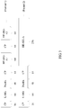
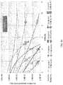
- FIG. 10 is a diagram of a functional relationship between either of a packet error rate and a miss rate that are each of multiple predetermined thresholds and a signal-to-noise ratio on an AWGN channel according to an embodiment of the present invention.
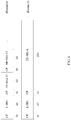
- FIG. 11 is a diagram of a functional relationship between either of a false alarm probability and a miss rate that are each of multiple predetermined thresholds and a signal-to-noise ratio on a UMi NLOS channel according to an embodiment of the present invention.
- th indicates a predetermined threshold that is a normalized autocorrelation value
- FA indicates a false alarm probability
- und indicates a miss rate. It may be learned from FIG. 10 and FIG. 11 that, when the predetermined threshold increases, the false alarm probability decreases, and the miss rate increases. Therefore, setting of a threshold needs to be considered in a balanced way, and neither a larger threshold nor a smaller threshold brings better effect.
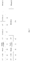
- FIG. 12 is evaluation performance of an L-SIG without a postfix and an L-SIG with a postfix on a UMi NLOS channel.
- a postfix for the L-SIG is separately 0, 24, 48, or 64.
- FIG. 13 is performance of an L-SIG without a postfix and an L-SIG with a postfix in an ideal channel estimation case, that is, during channel estimation, a noise 0 is assumed.
- a postfix for the L-SIG is separately 0, 24, 48, or 64.
- step 802 is specifically implemented as follows: acquiring an autocorrelation value of a first specified time domain sequence part in the first symbol and a second specified time domain sequence part and a third specified time domain sequence part that are in the second symbol, where the first specified time domain sequence part is first L time domain sequence bits of the information bearing section of the first symbol, the second specified part is first L time domain sequence bits of the second symbol, and the third specified part is last L time domain sequence bits of the second symbol, where 16 ⁇ L ⁇ 40.
- r i indicates an (
- r L +15 indicate time domain signal values of the first specified time domain sequence part
- r 80 ... r L +79 indicate time domain signal values of the second specified time domain sequence part
- r 160- L ... r 159 indicate time domain signal values of the third specified time domain sequence part.
- the acquiring an autocorrelation value of a first specified time domain sequence part in the first symbol and a second specified time domain sequence part and a third specified time domain sequence part that are in the second symbol is expressed by using the following formula:
- r i indicates an ( i - 80)
- r L +15 indicate time domain signal values of the first specified time domain sequence part
- r 80 ... r L +79 indicate time domain signal values of the second specified time domain sequence part
- r 160- L ... r 159 indicate time domain signal values of the third specified time domain sequence part.
- step 803 is specifically implemented as follows: when the autocorrelation value is greater than the predetermined threshold, determining content of the information bearing section of the first symbol according to last (L - 16) time domain sequence bits of the information bearing section of the first symbol and first (80 - L) time domain sequence bits in the time domain sequence of the second symbol.
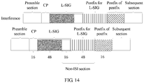
- FIG. 14 is a schematic diagram of a method for dynamically adjusting a pilot pattern according to a sparse channel according to an embodiment of the present invention.
- a non-ISI section may reduce ISI impact.
- a receive end may read the non-ISI section shown in FIG. 14 , to reduce the ISI impact and strengthen robustness of L-SIG signaling.
- This reading method is similar to the method for reading the non-ISI section in FIG. 9 , which is not described in this embodiment of the present invention.
- FIG. 15 is a schematic flowchart of wireless local area network packet transmission according to an embodiment of the present invention.
- a specific application scenario of this embodiment of the present invention is shown in FIG. 15 .
- a cyclic postfix for an L-SIG is added to a symbol following a symbol in which the L-SIG is located.
- An 11ax AP sends a packet of an indoor/outdoor scenario.
- the 11ax AP may send a packet of an 802.11ax format.
- the packet may be a packet of an indoor scenario, and a signaling format of an L-SIG and an HE-SIG in the packet may be shown as format 1 or format 2 in FIG. 4 .
- the packet may be a packet of an outdoor scenario, and a signaling format of an L-SIG and an HE-SIG in the packet may be shown as format 1 or format 2 in FIG. 3 or FIG. 7 .
- another data format may be used, which is not limited in this embodiment of the present invention.
- step 1502 if a receive end is an 11ax STA, step 1502 is performed. If the receive end is an 11a ⁇ g ⁇ ac STA, step 1512 is performed. If the received end is an 11n STA, step 1522 is performed.
- An 11ax STA performs autocorrelation detection on the transmitted packet.
- the 11ax STA performs the autocorrelation detection on the transmitted packet, and determines, according to a detection result, whether the transmitted packet is a packet structure in the indoor scenario or a packet structure in the outdoor scenario.
- the 11ax STA may perform the autocorrelation detection by using the foregoing Formula (1) or Formula (2).
- the 11ax STA may perform the autocorrelation detection by using the foregoing Formula (5), Formula (6), Formula (7), or Formula (8).
- the 11ax STA may perform the autocorrelation detection by using another similar formula, which is not limited in this embodiment of the present invention.
- the packet is a packet of an indoor scenario.
- Whether the packet is the packet of the indoor scenario may be determined by comparing an autocorrelation detection result and a predetermined threshold.
- step 1504 If the autocorrelation detection result is greater than the predetermined threshold, it may be determined that the packet is not the packet of the indoor scenario (or, the packet is a packet of an outdoor scenario), and step 1504 is performed.
- step 1505 If the autocorrelation detection result is less than the predetermined threshold, it may be determined that the packet is the packet of the indoor scenario, and step 1505 is performed.
- step 1504 may be performed or step 1505 may be performed.
- the 11ax STA reads an L-SIG section and continues to perform automatic detection of an 11ax indoor packet and an 11a/g/n/ac packet.
- the 11ax STA may further determine, by means of automatic detection of the packet, a version (11a/g/n/ac, or the like) to which the packet belongs.
- the 11ax STA obtains L-SIG information by reading a non-ISI section, and parses the transmitted packet.
- the 11ax STA may obtain the L-SIG information by reading the non-ISI section according to an agreed packet format of an outdoor scenario, and parse the transmitted packet.
- the 11ax STA may selectively continue to perform automatic detection of an 11ax outdoor packet and the 11a/g/n/ac packet.
- An 11a/g/ac STA reads an L-SIG of the packet.
- the 11a/g/ac STA reads the packet to acquire the L-SIG information in the packet.
- step 1514 If the L-SIG of the packet passes the parity check, step 1514 is performed; otherwise, step 1515 is performed.
- the 11a/g/ac STA determines a time for transmitting the packet, and is selectively dormant.
- the 11a/g/ac STA may determine the time for transmitting the packet, and then, is selectively dormant.
- the 11a/g/ac STA drops the packet.
- the L-SIG of the packet does not pass the parity check, it indicates that a version of the packet is not a version supported by the 11a/g/ac STA, and the 11a/g/ac STA may drop the packet.
- the 11n STA performs the automatic detection on the packet to determine whether the packet is a packet of an indoor scenario.
- the packet is a packet of an indoor scenario.
- step 1524 is performed; otherwise, step 1525 is performed.
- the 11n STA determines whether the packet is an 11n packet.
- the 11n STA may further determine whether the packet is an 11n version packet of an indoor scenario.
- the 11n STA parses the packet; otherwise, the 11n STA drops the packet.
- the 11n STA After determining that the packet is not the packet of the indoor scenario, the 11n STA assumes that the packet is a packet of an 11a/g format, and then when an error occurs on a cyclic redundancy check (CRC), drops the whole packet.
- CRC cyclic redundancy check
- the 11n STA directly drops the whole packet.
- the 11ax AP sends the packet, and STAs of various versions receive the packet.
- the 11ax STA may send a packet, and APs of various versions receive the packet.
- a cyclic postfix for an L-SIG is added after a symbol following a symbol in which the L-SIG is located in a packet of an outdoor scenario, so that a WLAN system can not only ensure backward compatibility, but also strengthen robustness of packet transmission to an extent by reducing ISI impact.
- FIG. 16 is a schematic structural diagram of a WLAN transmission device 1600 according to an embodiment of the present invention.
- the WLAN transmission device 1600 may be an AP or a STA.
- the WLAN transmission device 1600 may include a generation unit 1601 and a sending unit 1602.
- the generation unit 1601 is configured to generate a packet.
- First L time domain sequence bits of a second symbol in the packet are the same as first L time domain sequence bits of an information bearing section in a time domain sequence of a first symbol in the packet, the first symbol includes a cyclic prefix CP and the information bearing section, the second symbol is a symbol following the first symbol, a length of the CP is 16 bits, and a length of the information bearing section is 64 bits, where 1 ⁇ L ⁇ 64.
- the sending unit 1602 is configured to send the packet to a receive end, so that the receive end receives and parses the packet.
- the WLAN transmission device 1600 when transmitting the packet, the WLAN transmission device 1600 adds a cyclic postfix of the information bearing section of the first symbol after the first symbol of the packet of an outdoor scenario, which can not only ensure backward compatibility, but also strengthen robustness of packet transmission to an extent by reducing ISI impact.
- the WLAN transmission device 1600 may further execute the method in FIG. 1 , and implement methods of a wireless local area network transmit end device in embodiments shown in FIG. 1 and FIG. 15 , which is not described in this embodiment of the present invention.
- FIG. 17 is a schematic structural diagram of a WLAN transmission device 1700 according to an embodiment of the present invention.
- the WLAN transmission device 1700 may be an AP or a STA.
- the WLAN transmission device 1700 may include a generation unit 1701 and a sending unit 1702.
- the generation unit 1701 is configured to generate a packet.
- a time domain sequence of a second symbol in the packet includes a first time domain sequence part and a second time domain sequence part
- a first symbol in the packet includes a cyclic prefix CP and an information bearing section
- the first time domain sequence part is the same as first L time domain sequence bits of the information bearing section of the first symbol
- the second time domain sequence part is the same as first N time domain sequence bits of the first time domain sequence part
- the second symbol is a symbol following the first symbol
- a length of the CP is 16 bits
- the sending unit 1702 is configured to send the packet to a receive end, so that the receive end receives and parses the packet.
- the WLAN transmission device 1700 when transmitting the packet, adds a cyclic postfix of the information bearing section of the first symbol after the first symbol of the packet of an outdoor scenario, which can not only ensure backward compatibility, but also strengthen robustness of packet transmission to an extent by reducing ISI impact.
- the WLAN transmission device 1700 may further execute the method in FIG. 5 , and implement methods of a wireless local area network transmit end device in embodiments shown in FIG. 5 and FIG. 15 , which is not described in this embodiment of the present invention.
- FIG. 18 is a schematic structural diagram of a WLAN transmission device 1800 according to an embodiment of the present invention.
- the WLAN transmission device 1800 may be an AP or a STA.
- the WLAN transmission device 1800 may include a receiving unit 1801, an acquiring unit 1802, and a parsing unit 1803.
- the receiving unit 1801 is configured to receive a packet sent by a wireless local area network transmit end.
- the acquiring unit 1802 is configured to acquire an autocorrelation value of a specified time domain sequence part of a first symbol and a specified time domain sequence part of a second symbol in the packet.
- the specified time domain sequence part of the first symbol is all or a part of a time domain sequence of an information bearing section in the first symbol, the first symbol includes a cyclic prefix CP and the information bearing section, and the second symbol is a symbol following the first symbol, where a length of the CP is 16 bits, and a length of the information bearing section is 64 bits.
- the parsing unit 1803 is configured to determine, when the autocorrelation value is greater than a predetermined threshold, to parse the packet by using a signaling format of a first scenario; or determine, when the autocorrelation value is less than a predetermined threshold, to parse the packet by using a signaling format of a second scenario.
- the WLAN transmission device 1800 can determine, by comparing the autocorrelation value of the specified time domain sequence part of the first symbol and the specified time domain sequence part of a symbol following the first symbol in the packet, a scenario to which the packet belongs, and parse the packet by using a data format of this scenario.
- the acquiring unit 1802 is specifically configured to acquire an autocorrelation value of a first specified time domain sequence part in the first symbol and a second specified time domain sequence part in the second symbol, where the first specified time domain sequence part is first L time domain sequence bits of the information bearing section of the first symbol, and the second specified time domain sequence part is first L time domain sequence bits in a time domain sequence of the second symbol, where 1 ⁇ L ⁇ 64.
- the parsing unit 1803 is specifically configured to determine content of the information bearing section of the first symbol according to last (64 - L) time domain sequence bits of the information bearing section of the first symbol and the first L time domain sequence bits in the time domain sequence of the second symbol.
- the acquiring unit 1802 is specifically configured to acquire an autocorrelation value of a first specified time domain sequence part in the first symbol and a second specified time domain sequence part and a third specified time domain sequence part that are in the second symbol, where the first specified time domain sequence part is first L time domain sequence bits of the information bearing section of the first symbol, the second specified part is first L time domain sequence bits of the second symbol, and the third specified part is last L time domain sequence bits of the second symbol, where 16 ⁇ L ⁇ 40.
- the parsing unit 1803 is specifically configured to determine the content of the information bearing section of the first symbol according to last (L - 16) time domain sequence bits of the information bearing section of the first symbol and first (80 - L) time domain sequence bits in the time domain sequence of the second symbol.
- the WLAN transmission device 1800 may further execute the method in FIG. 8 , and implement methods of a wireless local area network receive end device in embodiments shown in FIG. 8 and FIG. 15 , which is not described in this embodiment of the present invention.
- FIG. 19 is a schematic structural diagram of a WLAN transmission device 1900 according to an embodiment of the present invention.
- the WLAN transmission device 1900 may be an AP or a STA.
- the WLAN transmission device 1900 may include a processor 1902, a memory 1903, a transmitter 1901, and a receiver 1903.
- the receiver 1904, the transmitter 1901, the processor 1902, and the memory 1903 are connected to each other by using a system of a bus 1906.
- the bus 1906 may be an ISA bus, a PCI bus, an EISA bus, or the like.
- the bus may be classified into an address bus, a data bus, a control bus, and the like. For convenience of representation, only one double-headed arrow is used in FIG. 19 for representation, which, however, does not mean that there is only one bus or one type of bus.
- the transmitter 1901 and the receiver 1904 may be coupled to an antenna 1905.
- the memory 1903 is configured to store a program.
- the program may include program code, and the program code includes a computer operation instruction.
- the memory 1903 may include a read-only memory and a random access memory, and provide an instruction and data for the processor 1902.
- the memory 1903 may include a high-speed RAM memory, and may further include a non-volatile memory (non-volatile memory), for example, at least one disk memory.
- the processor 1902 executes the program stored in the memory 1903, and is specifically configured to execute the following operations:
- the foregoing method that is disclosed in any embodiment in FIG. 1 or FIG. 15 of the present invention and is executed by a transmit end may be applied to the processor 1902, or implemented by the processor 1902.
- the processor 1902 may be an integrated circuit chip and have a signal processing capability.
- each step in the foregoing method may be completed by using an integrated logic circuit of hardware in the processor 1902 or an instruction in a form of software.
- the foregoing processor 1902 may be a general purpose processor that includes a central processing unit (Central Processing Unit, CPU for short), a network processor (Network Processor, NP for short), and the like; or may be a digital signal processor (DSP), an application-specific integrated circuit (ASIC), a field programmable gate array (FPGA) or another programmable logic device, a discrete gate or a transistor logic device, or a discrete hardware component, which may implement or execute various methods, steps, and logical block diagrams disclosed in this embodiment of the present invention.
- the general purpose processor may be a microprocessor, or the processor may be any normal processor.
- the steps of the method disclosed in the embodiments of the present invention may be executed and completed by a hardware decoding processor, or executed and completed by means of a combination of hardware and a software module in a decoding processor.
- the software module may be located in a mature storage medium in this field, such as a random access memory, a flash memory, a read-only memory, a programmable read-only memory, an electrically-erasable programmable memory, or a register.
- the storage medium is located in the memory 1903.
- the processor 1902 reads information in the memory 1903, and completes the steps of the foregoing method in combination with hardware of the memory 1903.
- the WLAN transmission device 1900 when transmitting the packet, the WLAN transmission device 1900 adds a cyclic postfix of the information bearing section of the first symbol after the first symbol of the packet of an outdoor scenario, which can not only ensure backward compatibility, but also strengthen robustness of packet transmission to an extent by reducing ISI impact.
- the WLAN transmission device 1900 may further execute the method in FIG. 1 , and implement methods of a wireless local area network transmit end device in embodiments shown in FIG. 1 and FIG. 15 , which is not described in this embodiment of the present invention.
- FIG. 20 is a schematic structural diagram of a WLAN transmission device 2000 according to an embodiment of the present invention.
- the WLAN transmission device 2000 may include a processor 2002, a memory 2003, a transmitter 2001, and a receiver 2003.
- the receiver 2004, the transmitter 2001, the processor 2002, and the memory 2003 are connected to each other by using a system of a bus 2006.
- the bus 2006 may be an ISA bus, a PCI bus, an EISA bus, or the like.
- the bus may be classified into an address bus, a data bus, a control bus, and the like. For convenience of representation, only one double-headed arrow is used in FIG. 20 for representation, which, however, does not mean that there is only one bus or one type of bus.
- the transmitter 2001 and the receiver 2004 may be coupled to an antenna 2005.
- the memory 2003 is configured to store a program.
- the program may include program code, and the program code includes a computer operation instruction.
- the memory 2003 may include a read-only memory and a random access memory, and provide an instruction and data for the processor 2002.
- the memory 2003 may include a high-speed RAM memory, and may further include a non-volatile memory (non-volatile memory), for example, at least one disk memory.
- the processor 2002 executes the program stored in the memory 2003, and is specifically configured to execute the following operations:
- the foregoing method that is disclosed in any embodiment in FIG. 5 or FIG. 15 of the present invention and is executed by a transmit end may be applied to the processor 2002, or implemented by the processor 2002.
- the processor 2002 may be an integrated circuit chip and have a signal processing capability.
- each step in the foregoing method may be completed by using an integrated logic circuit of hardware in the processor 2002 or an instruction in a form of software.
- the foregoing processor 2002 may be a general purpose processor that includes a central processing unit (Central Processing Unit, CPU for short), a network processor (Network Processor, NP for short), and the like; or may be a digital signal processor (DSP), an application-specific integrated circuit (ASIC), a field programmable gate array (FPGA) or another programmable logic device, a discrete gate or a transistor logic device, or a discrete hardware component, which may implement or execute various methods, steps, and logical block diagrams disclosed in this embodiment of the present invention.
- the general purpose processor may be a microprocessor, or the processor may be any normal processor.
- the steps of the method disclosed in the embodiments of the present invention may be executed and completed by a hardware decoding processor, or executed and completed by means of a combination of hardware and a software module in a decoding processor.
- the software module may be located in a mature storage medium in this field, such as a random access memory, a flash memory, a read-only memory, a programmable read-only memory, an electrically-erasable programmable memory, or a register.
- the storage medium is located in the memory 2003.
- the processor 2002 reads information in the memory 2003, and completes the steps of the foregoing method in combination with hardware of the memory 2003.
- the WLAN transmission device 2000 when transmitting the packet, the WLAN transmission device 2000 adds a cyclic postfix of the information bearing section of the first symbol after the first symbol of the packet of an outdoor scenario, which can not only ensure backward compatibility, but also strengthen robustness of packet transmission to an extent by reducing ISI impact.
- the WLAN transmission device 2000 may further execute the method in FIG. 5 , and implement methods of a wireless local area network transmit end device in embodiments shown in FIG. 5 and FIG. 15 , which is not described in this embodiment of the present invention.
- FIG. 21 is a schematic structural diagram of a WLAN transmission device 2100 according to an embodiment of the present invention.
- the WLAN transmission device 2100 may be an AP or a STA.
- the WLAN transmission device 2100 may include a processor 2102, a memory 2103, a transmitter 2101, and a receiver 2103.
- the receiver 2104, the transmitter 2101, the processor 2102, and the memory 2103 are connected to each other by using a system of a bus 2106.
- the bus 2106 may be an ISA bus, a PCI bus, an EISA bus, or the like.
- the bus may be classified into an address bus, a data bus, a control bus, and the like. For convenience of representation, only one double-headed arrow is used in FIG. 21 for representation, which, however, does not mean that there is only one bus or one type of bus.
- the transmitter 2101 and the receiver 2104 may be coupled to an antenna 2105.
- the memory 2103 is configured to store a program.
- the program may include program code, and the program code includes a computer operation instruction.
- the memory 2103 may include a read-only memory and a random access memory, and provide an instruction and data for the processor 2102.
- the memory 2103 may include a high-speed RAM memory, and may further include a non-volatile memory, for example, at least one disk memory.
- the processor 2102 executes the program stored in the memory 2103, and is specifically configured to execute the following operations:
- the foregoing method that is disclosed in any embodiment in FIG. 8 or FIG. 15 of the present invention and is executed by a receive end may be applied to the processor 2102, or implemented by the processor 2102.
- the processor 2102 may be an integrated circuit chip and have a signal processing capability.
- each step in the foregoing method may be completed by using an integrated logic circuit of hardware in the processor 2102 or an instruction in a form of software.
- the foregoing processor 2102 may be a general purpose processor that includes a central processing unit (CPU for short), a network processor (NP for short), and the like; or may be a digital signal processor (DSP), an application-specific integrated circuit (ASIC), a field programmable gate array (FPGA) or another programmable logic device, a discrete gate or a transistor logic device, or a discrete hardware component, which may implement or execute various methods, steps, and logical block diagrams disclosed in this embodiment of the present invention.
- the general purpose processor may be a microprocessor, or the processor may be any normal processor.
- the steps of the method disclosed in the embodiments of the present invention may be executed and completed by a hardware decoding processor, or executed and completed by means of a combination of hardware and a software module in a decoding processor.
- the software module may be located in a mature storage medium in this field, such as a random access memory, a flash memory, a read-only memory, a programmable read-only memory, an electrically-erasable programmable memory, or a register.
- the storage medium is located in the memory 2103.
- the processor 2102 reads information in the memory 2103, and completes the steps of the foregoing method in combination with hardware of the memory 2013.
- the WLAN transmission device 2100 can determine, by comparing the autocorrelation value of the specified time domain sequence part of the first symbol and the specified time domain sequence part of a symbol following the first symbol in the packet, a scenario to which the packet belongs, and parse the packet by using a data format of this scenario.
- the processor 2102 in a process of acquiring an autocorrelation value of a specified time domain sequence part of a first symbol and a specified time domain sequence part of a second symbol in the packet, is specifically configured to acquire an autocorrelation value of a first specified time domain sequence part in the first symbol and a second specified time domain sequence part in the second symbol, where the first specified time domain sequence part is first L time domain sequence bits of the information bearing section of the first symbol, and the second specified time domain sequence part is first L time domain sequence bits in a time domain sequence of the second symbol, where 1 ⁇ L ⁇ 64.
- the processor 2102 is specifically configured to determine content of the information bearing section of the first symbol according to last (64 - L) time domain sequence bits of the information bearing section of the first symbol and the first L time domain sequence bits in the time domain sequence of the second symbol.
- the processor 2102 in a process of acquiring an autocorrelation value of a specified time domain sequence part of a first symbol and a specified time domain sequence part of a second symbol in the packet, is specifically configured to acquire an autocorrelation value of a first specified time domain sequence part in the first symbol and a second specified time domain sequence part and a third specified time domain sequence part that are in the second symbol, where the first specified time domain sequence part is first L time domain sequence bits of the information bearing section of the first symbol, the second specified part is first L time domain sequence bits of the second symbol, and the third specified part is last L time domain sequence bits of the second symbol, where 16 ⁇ L ⁇ 40.
- the processor 2102 is specifically configured to determine the content of the information bearing section of the first symbol according to last (L - 16) time domain sequence bits of the information bearing section of the first symbol and first (80 - L) time domain sequence bits in the time domain sequence of the second symbol.
- the WLAN transmission device 2100 may further execute the method in FIG. 8 , and implement methods of a wireless local area network receive end device in embodiments shown in FIG. 8 and FIG. 15 , which is not described in this embodiment of the present invention.
- sequence numbers of the foregoing processes do not mean execution sequences in various embodiments of the present invention.
- the execution sequences of the processes should be determined according to functions and internal logic of the processes, and should not be construed as any limitation on the implementation processes of the embodiments of the present invention.
- the disclosed system, apparatus, and method may be implemented in other manners.
- the described apparatus embodiment is merely exemplary.
- the unit division is merely logical function division and may be other division in actual implementation.
- a plurality of units or components may be combined or integrated into another system, or some features may be ignored or not performed.
- the displayed or discussed mutual couplings or direct couplings or communication connections may be implemented by using some interfaces.
- the indirect couplings or communication connections between the apparatuses or units may be implemented in electronic, mechanical, or other forms.
- the units described as separate parts may or may not be physically separate, and parts displayed as units may or may not be physical units, may be located in one position, or may be distributed on a plurality of network units. Some or all of the units may be selected according to actual needs to achieve the objectives of the solutions of the embodiments.
- functional units in the embodiments of the present invention may be integrated into one processing unit, or each of the units may exist alone physically, or two or more units are integrated into one unit.
- the functions When the functions are implemented in the form of a software functional unit and sold or used as an independent product, the functions may be stored in a computer-readable storage medium. Based on such an understanding, the technical solutions of the present invention essentially, or the part contributing to the prior art, or some of the technical solutions may be implemented in a form of a software product.
- the software product is stored in a storage medium, and includes several instructions for instructing a computer device (which may be a personal computer, a server, or a network device) to perform all or some of the steps of the methods described in the embodiments of the present invention.
- the foregoing storage medium includes: any medium that can store program code, such as a USB flash drive, a removable hard disk, a read-only memory (ROM, Read-Only Memory), a random access memory (RAM, Random Access Memory), a magnetic disk, or an optical disc.
- program code such as a USB flash drive, a removable hard disk, a read-only memory (ROM, Read-Only Memory), a random access memory (RAM, Random Access Memory), a magnetic disk, or an optical disc.
Landscapes
- Engineering & Computer Science (AREA)
- Computer Networks & Wireless Communication (AREA)
- Signal Processing (AREA)
- Multimedia (AREA)
- Mobile Radio Communication Systems (AREA)
Claims (14)
- Übertragungsverfahren für ein drahtloses lokales Netzwerk (Wireless Local Area Network, WLAN), dadurch gekennzeichnet, dass das Verfahren umfasst:Erzeugen eines Pakets, wobei die ersten L Zeitbereichsequenzbits eines zweiten Symbols in dem Paket die gleichen sind wie die ersten L Zeitbereichsequenzbits eines informationstragenden Abschnitts in einer Zeitbereichsequenz eines ersten Symbols in dem Paket, das erste Symbol ein zyklisches Präfix (Cyclic Prefix, CP) und den informationstragenden Abschnitt umfasst, das zweite Symbol ein Symbol ist, das auf das erste Symbol folgt, eine Länge des CP 16 Bits beträgt und eine Länge des informationstragenden Abschnitts 64 Bits beträgt, wobei 1≤L<64; undSenden des Pakets an ein Empfangsende, sodass das Empfangsende das Paket empfängt und analysiert.
- Verfahren nach Anspruch 1, wobei das erste Symbol ein Symbol ist, in dem sich die bestehende Signalisierung (Legacy Signaling, L-SIG) befindet.
- Verfahren nach Anspruch 1 oder 2, wobei ein Wert von L 16, 24, 36 oder 48 ist.
- WLAN-Übertragungsverfahren, umfassend:Erzeugen eines Pakets, wobei eine Zeitbereichsequenz eines zweiten Symbols in dem Paket einen ersten Zeitbereichsequenzteil und einen zweiten Zeitbereichsequenzteil umfasst, ein erstes Symbol in dem Paket ein zyklisches Präfix (CP) und einen informationstragenden Abschnitt umfasst, der erste Zeitbereichsequenzteil der gleiche ist wie die ersten L Zeitbereichsequenzbits des informationstragenden Abschnitts des ersten Symbols, der zweite Zeitbereichsequenzteil der gleiche ist wie die ersten N Zeitbereichsequenzbits des ersten Zeitbereichsequenzteils, das zweite Symbol ein Symbol ist, das auf das erste Symbol folgt, eine Länge des CP 16 Bits beträgt und eine Länge des informationstragenden Abschnitts 64 Bits beträgt, wobei N+L=80 und 1≤N≤L ist; undSenden des Pakets an ein Empfangsende, sodass das Empfangsende das Paket empfängt und analysiert.
- Verfahren nach Anspruch 4, wobei das erste Symbol ein Symbol ist, in dem sich die L-SIG befindet.
- Verfahren nach Anspruch 4 oder 5, wobei ein Wert von L 48 ist und ein Wert von N 32 ist.
- WLAN-Übertragungsverfahren, wobei das Verfahren umfasst:Empfangen eines Pakets, das von einem WLAN-Übertragungsende gesendet wurde;Erfassen eines Autokorrelationswerts eines spezifizierten Zeitbereichsequenzteils eines ersten Symbols und eines spezifizierten Zeitbereichsequenzteils eines zweiten Symbols in dem Paket, wobei der spezifizierte Zeitbereichsequenzteil des ersten Symbols den gesamten oder einen Teil einer Zeitbereichsequenz eines informationstragenden Abschnitts in dem ersten Symbol darstellt, wobei das erste Symbol ein zyklisches Präfix (CP) und den informationstragenden Abschnitt umfasst und das zweite Symbol ein Symbol ist, das dem ersten Symbol folgt, wobei eine Länge des CP 16 Bits beträgt und eine Länge des informationstragenden Abschnitts 64 Bits beträgt; undBestimmen, wenn der Autokorrelationswert größer als ein vorbestimmter Schwellenwert ist, das Paket unter Verwendung eines Signalisierungsformats eines ersten Szenarios zu analysieren; oder Bestimmen, wenn der Autokorrelationswert kleiner als ein vorbestimmter Schwellenwert ist, das Paket unter Verwendung eines Signalisierungsformats eines zweiten Szenarios zu analysieren;wobei das Erfassen eines Autokorrelationswerts eines spezifizierten Zeitbereichsequenzteils eines ersten Symbols und eines spezifizierten Zeitbereichsequenzteils eines zweiten Symbols in dem Paket umfasst:
Erfassen eines Autokorrelationswerts eines ersten spezifizierten Zeitbereichsequenzteils in dem ersten Symbol und eines zweiten spezifizierten Zeitbereichsequenzteils in dem zweiten Symbol, wobei der erste spezifizierte Zeitbereichsequenzteil die ersten L Zeitbereichsequenzbits des informationstragenden Abschnitts des ersten Symbols darstellt und der zweite spezifizierte Zeitbereichsequenzteil die ersten L Zeitbereichsequenzbits in einer Zeitbereichsequenz des zweiten Symbols darstellt, wobei 1≤L<64. - Verfahren nach Anspruch 7, wobei das Erfassen eines Autokorrelationswerts eines ersten spezifizierten Zeitbereichsequenzteils in dem ersten Symbol und eines zweiten spezifizierten Zeitbereichsequenzteils in dem zweiten Symbol unter Verwendung der folgenden Formel ausgedrückt wird:


- WLAN-Übertragungsvorrichtung, umfassend:eine Erzeugungseinheit, die konfiguriert ist, um ein Paket zu erzeugen, wobei die ersten L Zeitbereichsequenzbits eines zweiten Symbols in dem Paket die gleichen sind wie die ersten L Zeitbereichsequenzbits eines informationstragenden Abschnitts in einer Zeitbereichsequenz eines ersten Symbols in dem Paket, das erste Symbol ein zyklisches Präfix (CP) und den informationstragenden Abschnitt umfasst, das zweite Symbol ein Symbol ist, das auf das erste Symbol folgt, eine Länge des CP 16 Bits beträgt und eine Länge des informationstragenden Abschnitts 64 Bits beträgt, wobei 1≤L<64; undeine Sendeeinheit, die konfiguriert ist, um das Paket an ein Empfangsende zu senden, sodass das Empfangsende das Paket empfängt und analysiert.
- WLAN-Übertragungsvorrichtung, umfassend:eine Erzeugungseinheit, die konfiguriert ist, um ein Paket zu erzeugen, wobei eine Zeitbereichsequenz eines zweiten Symbols in dem Paket einen ersten Zeitbereichsequenzteil und einen zweiten Zeitbereichsequenzteil umfasst, ein erstes Symbol in dem Paket ein zyklisches Präfix (CP) und einen informationstragenden Abschnitt umfasst, der erste Zeitbereichsequenzteil der gleiche ist wie die ersten L Zeitbereichsequenzbits des informationstragenden Abschnitts des ersten Symbols, der zweite Zeitbereichsequenzteil der gleiche ist wie die ersten N Zeitbereichsequenzbits des ersten Zeitbereichsequenzteils, das zweite Symbol ein Symbol ist, das auf das erste Symbol folgt, eine Länge des CP 16 Bits beträgt und eine Länge des informationstragenden Abschnitts 64 Bits beträgt, wobei N+L=80 und 1≤N≤L ist; undeine Sendeeinheit, die konfiguriert ist, um das Paket an ein Empfangsende zu senden, sodass das Empfangsende das Paket empfängt und analysiert.
- WLAN-Übertragungsvorrichtung, umfassend:eine Empfangseinheit, die konfiguriert ist, um ein Paket zu empfangen, das von einem WLAN-Übertragungsende gesendet wird;eine Erfassungseinheit, die konfiguriert ist, um einen Autokorrelationswert eines spezifizierten Zeitbereichsequenzteils eines ersten Symbols und eines spezifizierten Zeitbereichsequenzteils eines zweiten Symbols in dem Paket zu erfassen, wobei der spezifizierte Zeitbereichsequenzteil des ersten Symbols den gesamten oder einen Teil einer Zeitbereichsequenz eines informationstragenden Abschnitts in dem ersten Symbol darstellt, wobei das erste Symbol ein zyklisches Präfix (CP) und den informationstragenden Abschnitt umfasst und das zweite Symbol ein Symbol ist, das dem ersten Symbol folgt, wobei eine Länge des CP 16 Bits beträgt und eine Länge des informationstragenden Abschnitts 64 Bits beträgt; undeine Analyseeinheit, die konfiguriert ist, um zu bestimmen, wenn der Autokorrelationswert größer als ein vorbestimmter Schwellenwert ist, das Paket unter Verwendung eines Signalisierungsformats eines ersten Szenarios zu analysieren; oder zu bestimmen, wenn der Autokorrelationswert kleiner als ein vorbestimmter Schwellenwert ist, das Paket unter Verwendung eines Signalisierungsformats eines zweiten Szenarios zu analysieren;wobei die Erfassungseinheit insbesondere konfiguriert ist, um:
einen Autokorrelationswert eines ersten spezifizierten Zeitbereichsequenzteils in dem ersten Symbol und eines zweiten spezifizierten Zeitbereichsequenzteils in dem zweiten Symbol zu erfassen, wobei der erste spezifizierte Zeitbereichsequenzteil die ersten L Zeitbereichsequenzbits des informationstragenden Abschnitts des ersten Symbols darstellt und der zweite spezifizierte Zeitbereichsequenzteil die ersten L Zeitbereichsequenzbits in einer Zeitbereichsequenz des zweiten Symbols darstellt, wobei 1≤L<64. - WLAN-Übertragungsvorrichtung nach Anspruch 11, wobei in einem Prozess des Analysierens des Pakets unter Verwendung des Signalisierungsformats des ersten Szenarios die Analyseeinheit insbesondere konfiguriert ist, um:
den Inhalt des informationstragenden Abschnitts des ersten Symbols gemäß den letzten (64 - L) Zeitbereichsequenzbits des informationstragenden Abschnitts des ersten Symbols und den ersten L Zeitbereichsequenzbits in der Zeitbereichsequenz des zweiten Symbols zu bestimmen. - WLAN-Übertragungsvorrichtung nach Anspruch 11, wobei die Erfassungseinheit insbesondere konfiguriert ist, um:
einen Autokorrelationswert eines ersten spezifizierten Zeitbereichsequenzteils in dem ersten Symbol und eines zweiten spezifizierten Zeitbereichsequenzteils und eines dritten spezifizierten Zeitbereichsequenzteils, die sich in dem zweiten Symbol befinden, zu erfassen, wobei der erste spezifizierte Zeitbereichsequenzteil die ersten L Zeitbereichsequenzbits des informationstragenden Abschnitts des ersten Symbols darstellt, der zweite spezifizierte Teil die ersten L Zeitbereichsequenzbits des zweiten Symbols darstellt und der dritte spezifizierte Teil die letzten L Zeitbereichsequenzbits des zweiten Symbols darstellt, wobei 16≤L≤40. - WLAN-Übertragungsvorrichtung nach Anspruch 13, wobei in einem Prozess des Analysierens des Pakets unter Verwendung des Signalisierungsformats des ersten Szenarios die Analyseeinheit insbesondere konfiguriert ist, um:
den Inhalt des informationstragenden Abschnitts des ersten Symbols gemäß den letzten (L - 16) Zeitbereichsequenzbits des informationstragenden Abschnitts des ersten Symbols und den ersten (80 - L) Zeitbereichsequenzbits in der Zeitbereichsequenz des zweiten Symbols zu bestimmen.
Applications Claiming Priority (1)
| Application Number | Priority Date | Filing Date | Title |
|---|---|---|---|
| PCT/CN2014/082827 WO2016011619A1 (zh) | 2014-07-23 | 2014-07-23 | 无线局域网的传输方法及传输设备 |
Publications (3)
| Publication Number | Publication Date |
|---|---|
| EP3157277A1 EP3157277A1 (de) | 2017-04-19 |
| EP3157277A4 EP3157277A4 (de) | 2017-07-12 |
| EP3157277B1 true EP3157277B1 (de) | 2019-09-25 |
Family
ID=55162422
Family Applications (1)
| Application Number | Title | Priority Date | Filing Date |
|---|---|---|---|
| EP14897916.4A Active EP3157277B1 (de) | 2014-07-23 | 2014-07-23 | Übertragungsverfahren und übertragungsvorrichtung für wlan |
Country Status (4)
| Country | Link |
|---|---|
| US (1) | US10219177B2 (de) |
| EP (1) | EP3157277B1 (de) |
| CN (1) | CN105453607B (de) |
| WO (1) | WO2016011619A1 (de) |
Families Citing this family (4)
| Publication number | Priority date | Publication date | Assignee | Title |
|---|---|---|---|---|
| US20170208153A1 (en) * | 2014-08-04 | 2017-07-20 | Intel IP Corporation | Wireless device, method, and computer readable media for a high efficiency signal-a field in a high efficiency wireless local-area network |
| WO2016201739A1 (zh) | 2015-06-16 | 2016-12-22 | 华为技术有限公司 | 资源调度的方法、装置和设备 |
| EP3799484B1 (de) | 2018-06-20 | 2025-08-06 | Huawei Technologies Co., Ltd. | Sitzungsverarbeitungsverfahren und zugehörige vorrichtung |
| CN116016083B (zh) * | 2022-12-14 | 2024-10-11 | 湖南智领通信科技有限公司 | 无线局域网的精定时方法、装置和计算机设备 |
Family Cites Families (17)
| Publication number | Priority date | Publication date | Assignee | Title |
|---|---|---|---|---|
| US8363744B2 (en) * | 2001-06-10 | 2013-01-29 | Aloft Media, Llc | Method and system for robust, secure, and high-efficiency voice and packet transmission over ad-hoc, mesh, and MIMO communication networks |
| US9312929B2 (en) * | 2004-04-02 | 2016-04-12 | Rearden, Llc | System and methods to compensate for Doppler effects in multi-user (MU) multiple antenna systems (MAS) |
| US20080101451A1 (en) * | 2006-10-30 | 2008-05-01 | Haifeng Wang | Method and Apparatus for Subblock-Wise Frequency Domain Equalization |
| CN101175058B (zh) * | 2006-10-31 | 2010-05-19 | 中兴通讯股份有限公司 | 一种时分双工系统同步信道的发送方法 |
| US9313067B2 (en) * | 2007-08-14 | 2016-04-12 | Qualcomm Incorporated | Multi-bandwidth communication system using a shared baseband processor |
| CN101888360A (zh) * | 2009-05-15 | 2010-11-17 | 中兴通讯股份有限公司 | 一种随机接入信号的发射方法和装置及相关系统 |
| US7920599B1 (en) * | 2010-02-03 | 2011-04-05 | Anna University | Methods and systems for synchronizing wireless transmission of data packets |
| US9300511B2 (en) * | 2011-01-05 | 2016-03-29 | Qualcomm Incorporated | Method and apparatus for improving throughput of 5 MHZ WLAN transmissions |
| US8774222B2 (en) * | 2011-02-10 | 2014-07-08 | Electronics And Telecommunications Research Institute | Method for generating and transmitting frame in a wireless local area network and apparatus for supporting the same |
| CN102695193B (zh) * | 2011-03-25 | 2015-12-02 | 中国移动通信集团公司 | 一种交叉子帧干扰检测方法、定位方法及基站 |
| US9774378B2 (en) * | 2011-04-24 | 2017-09-26 | Avago Technologies General Ip (Singapore) Pte. Ltd. | Preamble design within wireless communications |
| CN102255836B (zh) * | 2011-07-19 | 2014-03-12 | 宁波大学 | 一种基于mimo-ofdm信号循环平稳特性的盲信噪比估计方法 |
| CN103299693B (zh) * | 2011-12-31 | 2016-07-13 | 华为技术有限公司 | 正交频分多址接入方法、装置和系统 |
| US10194006B2 (en) * | 2013-10-25 | 2019-01-29 | Marvell World Trade Ltd. | Physical layer frame format for WLAN |
| US10218822B2 (en) * | 2013-10-25 | 2019-02-26 | Marvell World Trade Ltd. | Physical layer frame format for WLAN |
| KR20150128613A (ko) * | 2014-05-09 | 2015-11-18 | 뉴라컴 인코포레이티드 | 프레임 전송 및 수신 방법 |
| WO2016049935A1 (zh) * | 2014-09-30 | 2016-04-07 | 华为技术有限公司 | 无线局域网的帧传输方法和装置 |
-
2014
- 2014-07-23 EP EP14897916.4A patent/EP3157277B1/de active Active
- 2014-07-23 WO PCT/CN2014/082827 patent/WO2016011619A1/zh not_active Ceased
- 2014-07-23 CN CN201480043544.4A patent/CN105453607B/zh active Active
-
2017
- 2017-01-20 US US15/411,019 patent/US10219177B2/en active Active
Non-Patent Citations (1)
| Title |
|---|
| None * |
Also Published As
| Publication number | Publication date |
|---|---|
| EP3157277A4 (de) | 2017-07-12 |
| WO2016011619A1 (zh) | 2016-01-28 |
| CN105453607B (zh) | 2019-04-26 |
| US20170134983A1 (en) | 2017-05-11 |
| CN105453607A (zh) | 2016-03-30 |
| US10219177B2 (en) | 2019-02-26 |
| EP3157277A1 (de) | 2017-04-19 |
Similar Documents
| Publication | Publication Date | Title |
|---|---|---|
| US12022449B2 (en) | Data transmission method and apparatus | |
| JP5783579B2 (ja) | 通信デバイスに実装される方法および通信デバイス | |
| US11398938B2 (en) | Physical layer protocol data unit transmission method and apparatus | |
| CN107534534B (zh) | 物理层协议数据单元的传输方法和装置 | |
| EP3595394B1 (de) | Verfahren und vorrichtung zum senden und empfangen mit wahlfreiem zugriff, sende- und empfangsseite | |
| US20190297146A1 (en) | Communication format for a wireless network | |
| EP3393095B1 (de) | Doppelte verwendung der doppler-modusanzeige in einem hocheffizienten drahtlosen lan | |
| CN112564868B (zh) | 一种信号的发送、接收方法及终端 | |
| US10219177B2 (en) | Wireless local area network transmission method and transmission device | |
| WO2020010858A1 (zh) | 一种信令字段指示方法及装置 | |
| US20250150315A1 (en) | Data sending and receiving method and apparatus | |
| WO2020088637A1 (zh) | 信号的发送方法及终端 | |
| WO2014082575A1 (zh) | 一种物理广播信道传输方法、设备和系统 | |
| CN107529354B (zh) | 一种数据传输方法和传输装置 | |
| CN106664600B (zh) | 无线局域网的帧传输方法和装置 | |
| US20190342043A1 (en) | Data receiving method, data sending method, receiving device, and sending device | |
| US11025397B2 (en) | Quick acknowledgement reply method and apparatus | |
| CN111163025B (zh) | 一种获取、配置子帧结构的方法及网络设备 | |
| WO2016191991A1 (zh) | 物理层协议数据单元的传输方法和装置 |
Legal Events
| Date | Code | Title | Description |
|---|---|---|---|
| STAA | Information on the status of an ep patent application or granted ep patent |
Free format text: STATUS: THE INTERNATIONAL PUBLICATION HAS BEEN MADE |
|
| PUAI | Public reference made under article 153(3) epc to a published international application that has entered the european phase |
Free format text: ORIGINAL CODE: 0009012 |
|
| STAA | Information on the status of an ep patent application or granted ep patent |
Free format text: STATUS: REQUEST FOR EXAMINATION WAS MADE |
|
| 17P | Request for examination filed |
Effective date: 20170113 |
|
| AK | Designated contracting states |
Kind code of ref document: A1 Designated state(s): AL AT BE BG CH CY CZ DE DK EE ES FI FR GB GR HR HU IE IS IT LI LT LU LV MC MK MT NL NO PL PT RO RS SE SI SK SM TR |
|
| AX | Request for extension of the european patent |
Extension state: BA ME |
|
| A4 | Supplementary search report drawn up and despatched |
Effective date: 20170614 |
|
| RIC1 | Information provided on ipc code assigned before grant |
Ipc: H04L 5/00 20060101ALI20170608BHEP Ipc: H04W 52/02 20090101ALI20170608BHEP Ipc: H04W 4/06 20090101AFI20170608BHEP |
|
| DAX | Request for extension of the european patent (deleted) | ||
| GRAP | Despatch of communication of intention to grant a patent |
Free format text: ORIGINAL CODE: EPIDOSNIGR1 |
|
| STAA | Information on the status of an ep patent application or granted ep patent |
Free format text: STATUS: GRANT OF PATENT IS INTENDED |
|
| RIC1 | Information provided on ipc code assigned before grant |
Ipc: H04W 52/02 20090101ALI20190430BHEP Ipc: H04W 4/06 20090101AFI20190430BHEP Ipc: H04L 5/00 20060101ALI20190430BHEP |
|
| INTG | Intention to grant announced |
Effective date: 20190521 |
|
| GRAS | Grant fee paid |
Free format text: ORIGINAL CODE: EPIDOSNIGR3 |
|
| GRAA | (expected) grant |
Free format text: ORIGINAL CODE: 0009210 |
|
| STAA | Information on the status of an ep patent application or granted ep patent |
Free format text: STATUS: THE PATENT HAS BEEN GRANTED |
|
| AK | Designated contracting states |
Kind code of ref document: B1 Designated state(s): AL AT BE BG CH CY CZ DE DK EE ES FI FR GB GR HR HU IE IS IT LI LT LU LV MC MK MT NL NO PL PT RO RS SE SI SK SM TR |
|
| REG | Reference to a national code |
Ref country code: GB Ref legal event code: FG4D |
|
| REG | Reference to a national code |
Ref country code: CH Ref legal event code: EP |
|
| REG | Reference to a national code |
Ref country code: AT Ref legal event code: REF Ref document number: 1185033 Country of ref document: AT Kind code of ref document: T Effective date: 20191015 |
|
| REG | Reference to a national code |
Ref country code: IE Ref legal event code: FG4D |
|
| REG | Reference to a national code |
Ref country code: DE Ref legal event code: R096 Ref document number: 602014054408 Country of ref document: DE |
|
| REG | Reference to a national code |
Ref country code: NL Ref legal event code: MP Effective date: 20190925 |
|
| PG25 | Lapsed in a contracting state [announced via postgrant information from national office to epo] |
Ref country code: BG Free format text: LAPSE BECAUSE OF FAILURE TO SUBMIT A TRANSLATION OF THE DESCRIPTION OR TO PAY THE FEE WITHIN THE PRESCRIBED TIME-LIMIT Effective date: 20191225 Ref country code: HR Free format text: LAPSE BECAUSE OF FAILURE TO SUBMIT A TRANSLATION OF THE DESCRIPTION OR TO PAY THE FEE WITHIN THE PRESCRIBED TIME-LIMIT Effective date: 20190925 Ref country code: SE Free format text: LAPSE BECAUSE OF FAILURE TO SUBMIT A TRANSLATION OF THE DESCRIPTION OR TO PAY THE FEE WITHIN THE PRESCRIBED TIME-LIMIT Effective date: 20190925 Ref country code: FI Free format text: LAPSE BECAUSE OF FAILURE TO SUBMIT A TRANSLATION OF THE DESCRIPTION OR TO PAY THE FEE WITHIN THE PRESCRIBED TIME-LIMIT Effective date: 20190925 Ref country code: NO Free format text: LAPSE BECAUSE OF FAILURE TO SUBMIT A TRANSLATION OF THE DESCRIPTION OR TO PAY THE FEE WITHIN THE PRESCRIBED TIME-LIMIT Effective date: 20191225 Ref country code: LT Free format text: LAPSE BECAUSE OF FAILURE TO SUBMIT A TRANSLATION OF THE DESCRIPTION OR TO PAY THE FEE WITHIN THE PRESCRIBED TIME-LIMIT Effective date: 20190925 |
|
| REG | Reference to a national code |
Ref country code: LT Ref legal event code: MG4D |
|
| PG25 | Lapsed in a contracting state [announced via postgrant information from national office to epo] |
Ref country code: LV Free format text: LAPSE BECAUSE OF FAILURE TO SUBMIT A TRANSLATION OF THE DESCRIPTION OR TO PAY THE FEE WITHIN THE PRESCRIBED TIME-LIMIT Effective date: 20190925 Ref country code: GR Free format text: LAPSE BECAUSE OF FAILURE TO SUBMIT A TRANSLATION OF THE DESCRIPTION OR TO PAY THE FEE WITHIN THE PRESCRIBED TIME-LIMIT Effective date: 20191226 Ref country code: RS Free format text: LAPSE BECAUSE OF FAILURE TO SUBMIT A TRANSLATION OF THE DESCRIPTION OR TO PAY THE FEE WITHIN THE PRESCRIBED TIME-LIMIT Effective date: 20190925 |
|
| REG | Reference to a national code |
Ref country code: AT Ref legal event code: MK05 Ref document number: 1185033 Country of ref document: AT Kind code of ref document: T Effective date: 20190925 |
|
| PG25 | Lapsed in a contracting state [announced via postgrant information from national office to epo] |
Ref country code: AL Free format text: LAPSE BECAUSE OF FAILURE TO SUBMIT A TRANSLATION OF THE DESCRIPTION OR TO PAY THE FEE WITHIN THE PRESCRIBED TIME-LIMIT Effective date: 20190925 Ref country code: PT Free format text: LAPSE BECAUSE OF FAILURE TO SUBMIT A TRANSLATION OF THE DESCRIPTION OR TO PAY THE FEE WITHIN THE PRESCRIBED TIME-LIMIT Effective date: 20200127 Ref country code: ES Free format text: LAPSE BECAUSE OF FAILURE TO SUBMIT A TRANSLATION OF THE DESCRIPTION OR TO PAY THE FEE WITHIN THE PRESCRIBED TIME-LIMIT Effective date: 20190925 Ref country code: PL Free format text: LAPSE BECAUSE OF FAILURE TO SUBMIT A TRANSLATION OF THE DESCRIPTION OR TO PAY THE FEE WITHIN THE PRESCRIBED TIME-LIMIT Effective date: 20190925 Ref country code: IT Free format text: LAPSE BECAUSE OF FAILURE TO SUBMIT A TRANSLATION OF THE DESCRIPTION OR TO PAY THE FEE WITHIN THE PRESCRIBED TIME-LIMIT Effective date: 20190925 Ref country code: EE Free format text: LAPSE BECAUSE OF FAILURE TO SUBMIT A TRANSLATION OF THE DESCRIPTION OR TO PAY THE FEE WITHIN THE PRESCRIBED TIME-LIMIT Effective date: 20190925 Ref country code: NL Free format text: LAPSE BECAUSE OF FAILURE TO SUBMIT A TRANSLATION OF THE DESCRIPTION OR TO PAY THE FEE WITHIN THE PRESCRIBED TIME-LIMIT Effective date: 20190925 Ref country code: RO Free format text: LAPSE BECAUSE OF FAILURE TO SUBMIT A TRANSLATION OF THE DESCRIPTION OR TO PAY THE FEE WITHIN THE PRESCRIBED TIME-LIMIT Effective date: 20190925 Ref country code: AT Free format text: LAPSE BECAUSE OF FAILURE TO SUBMIT A TRANSLATION OF THE DESCRIPTION OR TO PAY THE FEE WITHIN THE PRESCRIBED TIME-LIMIT Effective date: 20190925 |
|
| PG25 | Lapsed in a contracting state [announced via postgrant information from national office to epo] |
Ref country code: SM Free format text: LAPSE BECAUSE OF FAILURE TO SUBMIT A TRANSLATION OF THE DESCRIPTION OR TO PAY THE FEE WITHIN THE PRESCRIBED TIME-LIMIT Effective date: 20190925 Ref country code: CZ Free format text: LAPSE BECAUSE OF FAILURE TO SUBMIT A TRANSLATION OF THE DESCRIPTION OR TO PAY THE FEE WITHIN THE PRESCRIBED TIME-LIMIT Effective date: 20190925 Ref country code: IS Free format text: LAPSE BECAUSE OF FAILURE TO SUBMIT A TRANSLATION OF THE DESCRIPTION OR TO PAY THE FEE WITHIN THE PRESCRIBED TIME-LIMIT Effective date: 20200224 Ref country code: SK Free format text: LAPSE BECAUSE OF FAILURE TO SUBMIT A TRANSLATION OF THE DESCRIPTION OR TO PAY THE FEE WITHIN THE PRESCRIBED TIME-LIMIT Effective date: 20190925 |
|
| REG | Reference to a national code |
Ref country code: DE Ref legal event code: R097 Ref document number: 602014054408 Country of ref document: DE |
|
| PG2D | Information on lapse in contracting state deleted |
Ref country code: IS |
|
| PG25 | Lapsed in a contracting state [announced via postgrant information from national office to epo] |
Ref country code: DK Free format text: LAPSE BECAUSE OF FAILURE TO SUBMIT A TRANSLATION OF THE DESCRIPTION OR TO PAY THE FEE WITHIN THE PRESCRIBED TIME-LIMIT Effective date: 20190925 Ref country code: IS Free format text: LAPSE BECAUSE OF FAILURE TO SUBMIT A TRANSLATION OF THE DESCRIPTION OR TO PAY THE FEE WITHIN THE PRESCRIBED TIME-LIMIT Effective date: 20200126 |
|
| PLBE | No opposition filed within time limit |
Free format text: ORIGINAL CODE: 0009261 |
|
| STAA | Information on the status of an ep patent application or granted ep patent |
Free format text: STATUS: NO OPPOSITION FILED WITHIN TIME LIMIT |
|
| 26N | No opposition filed |
Effective date: 20200626 |
|
| PG25 | Lapsed in a contracting state [announced via postgrant information from national office to epo] |
Ref country code: SI Free format text: LAPSE BECAUSE OF FAILURE TO SUBMIT A TRANSLATION OF THE DESCRIPTION OR TO PAY THE FEE WITHIN THE PRESCRIBED TIME-LIMIT Effective date: 20190925 |
|
| PG25 | Lapsed in a contracting state [announced via postgrant information from national office to epo] |
Ref country code: MC Free format text: LAPSE BECAUSE OF FAILURE TO SUBMIT A TRANSLATION OF THE DESCRIPTION OR TO PAY THE FEE WITHIN THE PRESCRIBED TIME-LIMIT Effective date: 20190925 |
|
| REG | Reference to a national code |
Ref country code: CH Ref legal event code: PL |
|
| GBPC | Gb: european patent ceased through non-payment of renewal fee |
Effective date: 20200723 |
|
| REG | Reference to a national code |
Ref country code: BE Ref legal event code: MM Effective date: 20200731 |
|
| PG25 | Lapsed in a contracting state [announced via postgrant information from national office to epo] |
Ref country code: FR Free format text: LAPSE BECAUSE OF NON-PAYMENT OF DUE FEES Effective date: 20200731 Ref country code: LI Free format text: LAPSE BECAUSE OF NON-PAYMENT OF DUE FEES Effective date: 20200731 Ref country code: LU Free format text: LAPSE BECAUSE OF NON-PAYMENT OF DUE FEES Effective date: 20200723 Ref country code: CH Free format text: LAPSE BECAUSE OF NON-PAYMENT OF DUE FEES Effective date: 20200731 Ref country code: GB Free format text: LAPSE BECAUSE OF NON-PAYMENT OF DUE FEES Effective date: 20200723 |
|
| PG25 | Lapsed in a contracting state [announced via postgrant information from national office to epo] |
Ref country code: BE Free format text: LAPSE BECAUSE OF NON-PAYMENT OF DUE FEES Effective date: 20200731 |
|
| PG25 | Lapsed in a contracting state [announced via postgrant information from national office to epo] |
Ref country code: IE Free format text: LAPSE BECAUSE OF NON-PAYMENT OF DUE FEES Effective date: 20200723 |
|
| PG25 | Lapsed in a contracting state [announced via postgrant information from national office to epo] |
Ref country code: TR Free format text: LAPSE BECAUSE OF FAILURE TO SUBMIT A TRANSLATION OF THE DESCRIPTION OR TO PAY THE FEE WITHIN THE PRESCRIBED TIME-LIMIT Effective date: 20190925 Ref country code: MT Free format text: LAPSE BECAUSE OF FAILURE TO SUBMIT A TRANSLATION OF THE DESCRIPTION OR TO PAY THE FEE WITHIN THE PRESCRIBED TIME-LIMIT Effective date: 20190925 Ref country code: CY Free format text: LAPSE BECAUSE OF FAILURE TO SUBMIT A TRANSLATION OF THE DESCRIPTION OR TO PAY THE FEE WITHIN THE PRESCRIBED TIME-LIMIT Effective date: 20190925 |
|
| PG25 | Lapsed in a contracting state [announced via postgrant information from national office to epo] |
Ref country code: MK Free format text: LAPSE BECAUSE OF FAILURE TO SUBMIT A TRANSLATION OF THE DESCRIPTION OR TO PAY THE FEE WITHIN THE PRESCRIBED TIME-LIMIT Effective date: 20190925 |
|
| PGFP | Annual fee paid to national office [announced via postgrant information from national office to epo] |
Ref country code: DE Payment date: 20250604 Year of fee payment: 12 |