EP3157162B1 - Motor control device, and method for correcting torque constant in such motor control device - Google Patents
Motor control device, and method for correcting torque constant in such motor control device Download PDFInfo
- Publication number
- EP3157162B1 EP3157162B1 EP16742977.8A EP16742977A EP3157162B1 EP 3157162 B1 EP3157162 B1 EP 3157162B1 EP 16742977 A EP16742977 A EP 16742977A EP 3157162 B1 EP3157162 B1 EP 3157162B1
- Authority
- EP
- European Patent Office
- Prior art keywords
- motor
- torque
- speed
- correction
- voltage
- Prior art date
- Legal status (The legal status is an assumption and is not a legal conclusion. Google has not performed a legal analysis and makes no representation as to the accuracy of the status listed.)
- Active
Links
Images


Classifications
-
- H—ELECTRICITY
- H02—GENERATION; CONVERSION OR DISTRIBUTION OF ELECTRIC POWER
- H02P—CONTROL OR REGULATION OF ELECTRIC MOTORS, ELECTRIC GENERATORS OR DYNAMO-ELECTRIC CONVERTERS; CONTROLLING TRANSFORMERS, REACTORS OR CHOKE COILS
- H02P21/00—Arrangements or methods for the control of electric machines by vector control, e.g. by control of field orientation
- H02P21/0003—Control strategies in general, e.g. linear type, e.g. P, PI, PID, using robust control
- H02P21/0025—Control strategies in general, e.g. linear type, e.g. P, PI, PID, using robust control implementing a off line learning phase to determine and store useful data for on-line control
-
- H—ELECTRICITY
- H02—GENERATION; CONVERSION OR DISTRIBUTION OF ELECTRIC POWER
- H02P—CONTROL OR REGULATION OF ELECTRIC MOTORS, ELECTRIC GENERATORS OR DYNAMO-ELECTRIC CONVERTERS; CONTROLLING TRANSFORMERS, REACTORS OR CHOKE COILS
- H02P23/00—Arrangements or methods for the control of AC motors characterised by a control method other than vector control
- H02P23/0004—Control strategies in general, e.g. linear type, e.g. P, PI, PID, using robust control
- H02P23/0031—Control strategies in general, e.g. linear type, e.g. P, PI, PID, using robust control implementing a off line learning phase to determine and store useful data for on-line control
-
- H—ELECTRICITY
- H02—GENERATION; CONVERSION OR DISTRIBUTION OF ELECTRIC POWER
- H02P—CONTROL OR REGULATION OF ELECTRIC MOTORS, ELECTRIC GENERATORS OR DYNAMO-ELECTRIC CONVERTERS; CONTROLLING TRANSFORMERS, REACTORS OR CHOKE COILS
- H02P21/00—Arrangements or methods for the control of electric machines by vector control, e.g. by control of field orientation
-
- H—ELECTRICITY
- H02—GENERATION; CONVERSION OR DISTRIBUTION OF ELECTRIC POWER
- H02P—CONTROL OR REGULATION OF ELECTRIC MOTORS, ELECTRIC GENERATORS OR DYNAMO-ELECTRIC CONVERTERS; CONTROLLING TRANSFORMERS, REACTORS OR CHOKE COILS
- H02P21/00—Arrangements or methods for the control of electric machines by vector control, e.g. by control of field orientation
- H02P21/14—Estimation or adaptation of machine parameters, e.g. flux, current or voltage
- H02P21/20—Estimation of torque
-
- H—ELECTRICITY
- H02—GENERATION; CONVERSION OR DISTRIBUTION OF ELECTRIC POWER
- H02P—CONTROL OR REGULATION OF ELECTRIC MOTORS, ELECTRIC GENERATORS OR DYNAMO-ELECTRIC CONVERTERS; CONTROLLING TRANSFORMERS, REACTORS OR CHOKE COILS
- H02P27/00—Arrangements or methods for the control of AC motors characterised by the kind of supply voltage
- H02P27/04—Arrangements or methods for the control of AC motors characterised by the kind of supply voltage using variable-frequency supply voltage, e.g. inverter or converter supply voltage
- H02P27/06—Arrangements or methods for the control of AC motors characterised by the kind of supply voltage using variable-frequency supply voltage, e.g. inverter or converter supply voltage using DC to AC converters or inverters
-
- H—ELECTRICITY
- H02—GENERATION; CONVERSION OR DISTRIBUTION OF ELECTRIC POWER
- H02P—CONTROL OR REGULATION OF ELECTRIC MOTORS, ELECTRIC GENERATORS OR DYNAMO-ELECTRIC CONVERTERS; CONTROLLING TRANSFORMERS, REACTORS OR CHOKE COILS
- H02P6/00—Arrangements for controlling synchronous motors or other dynamo-electric motors using electronic commutation dependent on the rotor position; Electronic commutators therefor
- H02P6/08—Arrangements for controlling the speed or torque of a single motor
-
- H—ELECTRICITY
- H02—GENERATION; CONVERSION OR DISTRIBUTION OF ELECTRIC POWER
- H02P—CONTROL OR REGULATION OF ELECTRIC MOTORS, ELECTRIC GENERATORS OR DYNAMO-ELECTRIC CONVERTERS; CONTROLLING TRANSFORMERS, REACTORS OR CHOKE COILS
- H02P6/00—Arrangements for controlling synchronous motors or other dynamo-electric motors using electronic commutation dependent on the rotor position; Electronic commutators therefor
- H02P6/10—Arrangements for controlling torque ripple, e.g. providing reduced torque ripple
-
- H—ELECTRICITY
- H02—GENERATION; CONVERSION OR DISTRIBUTION OF ELECTRIC POWER
- H02P—CONTROL OR REGULATION OF ELECTRIC MOTORS, ELECTRIC GENERATORS OR DYNAMO-ELECTRIC CONVERTERS; CONTROLLING TRANSFORMERS, REACTORS OR CHOKE COILS
- H02P2205/00—Indexing scheme relating to controlling arrangements characterised by the control loops
- H02P2205/05—Torque loop, i.e. comparison of the motor torque with a torque reference
Definitions
- the present invention relates to motor control devices for controlling a synchronous motor and methods of calculating a correction torque coefficient in the motor control devices.
- a conversion coefficient that expresses a relationship between a torque command and actual torque that is actually output from the motor is generally called a torque constant.
- the torque constant is a fixed value that does not change with speed or current and configures a speed control system.
- the actual torque constant is not always fixed. The torque constant may not be fixed due to an influence of current flowing in the motor and a current control circuit.
- PTL1 discloses a conventional method as a technical measure to cope with it.
- PTL1 has a means to measure actual output torque relative to the torque command by actually driving the motor, and correct the torque command.
- PTL1 controls the motor using this corrected torque command, so as to keep a fixed torque constant.
- the above conventional method can correct the torque constant according to motor specifications, but cannot correct an influence of individual differences, such as variation in motor production and variation in characteristic of electronic components in a drive circuit.
- the rotating electric machine control device disclosed in WO 2010/116769 A1 comprises a power converter for driving a rotating electric machine, a DC voltage detection means for detecting a DC voltage applied to the power converter, and a control unit for controlling the operation of the power converter.
- the control unit includes a terminal voltage fixing means that calculates the terminal voltage of the rotating electric machine on the basis of the DC voltage detected by the DC voltage detection means and d-axis and q-axis voltage commands from a voltage command calculation means and performs control for outputting a d-axis current correction value for correcting a d-axis current command so that the calculated terminal voltage matches a terminal voltage command that is a preset control target value, thereby maintaining the terminal voltage to be constant.
- JP 2008 220155 A discloses a motor controller.
- An angle computing portion obtains an angle of a rotor, and an angular velocity computing portion obtains the angular velocity of the rotor.
- a command current computing portion obtains command currents on a dq axis, based on steering torque T and a vehicle velocity S.
- An open loop control portion obtains command voltages on the dq axis, in accordance with a circuit equation of the motor, based on the command currents and an angular velocity.
- a dq axis/three-phase conversion portion converts the command voltages into three-phase command voltages.
- a ⁇ -computing portion obtains the number ⁇ of the linkage magnetic flux of an armature winding contained in the circuit equation of the motor, based on a q-axis command voltage, a current value detected by a current sensor, and the angular velocity.
- a motor control device includes a speed control part for controlling a motor rotation speed, and a torque correction means for suppressing variation in torque constant due to individual differences of motors. This eliminates influence of torque variation in individual motors and thus achieves high-precision torque control.
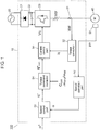
- Fig. 1 is a block diagram of brushless motor 100 equipped with motor control device 10 in the first exemplary embodiment of the present invention.
- brushless motor 100 in the exemplary embodiment includes motor control device 10 and synchronous motor 40.
- Synchronous motor 40 which is a motor in the exemplary embodiment, rotates by applying current and driving synchronous motor 40 with motor control device 10.
- rectifying circuit 21 rectifies AC voltage from AC power source 20 to DC voltage. This is then smoothed by smoothing capacitor 22. Then, the DC voltage is supplied to three-phase inverter 23 in motor control device 10. Three-phase inverter 23 converts supplied DV voltage to required AC voltage. A drive voltage of this AC voltage is supplied to synchronous motor 40 including a permanent magnet. In this way, three-phase synchronous motor 40 having U phase, V phase, and W phase shifted by 120 degrees to each other is driven in the exemplary embodiment.
- Fig. 2 is an example of a structure of synchronous motor 40 in the exemplary embodiment.
- synchronous motor 40 includes rotor 41 and stator 45.
- Rotor 41 holds permanent magnet 43 centering on shaft 42.
- Stator 45 is configured by winding motor coil 40 around stator core 46.
- brushless motor 100 has built-in circuit components 48p that function as motor control device 10 in synchronous motor 40. These circuit components 48p are mounted on circuit board 48b.
- a switching element configuring inverter 23 is mounted on circuit board 48b.
- position detector 51 for detecting a rotating position of rotor 41 is disposed facing permanent magnet 43 of rotor 41.
- three-phase AC voltage from inverter 23 is applied to motor coil 47 of each phase to energizing and drive motor coils 47, and rotor 41 rotates while being rotatably supported by bearing 44.
- motor control device 10 includes current detector 31, torque converter 32, speed operation part 52, speed control part 53, torque command corrector 54, and current control part 55 in the exemplary embodiment shown in Fig. 1 , in addition to inverter 23 described above, so as to control the rotation of rotor 41. Still more, motor control device 10 receives rotor position information Pr indicating the rotor position from position detector 51. Furthermore, motor control device 10 receives speed command ⁇ * for controlling the rotation speed typically from an external controller, as a command for controlling the rotation of synchronous motor 40.
- speed operation part 52 calculates a motor speed based on rotor position information Pr detected by position detector 51 typically by differential operation. This is informed to speed control part 53 as detected speed ⁇ .
- Speed control part 53 calculates and outputs torque command iq* that makes deviation between speed command ⁇ * and detected speed ⁇ zero. In other words, the speed control part calculates torque command iq* based on the deviation between speed command ⁇ * and detected speed ⁇ .
- Torque command corrector 54 corrects the torque command by multiplying torque command iq* output from speed control part 53 by correction torque coefficient C (crr) , and sends corrected torque command iq* (crr) obtained to current control part 55.
- torque command corrector 54 is provided to further correct the torque command based on speed deviation, so as to keep a fixed torque constant.
- the exemplary embodiment includes this torque command corrector 54 as a torque correction means for making corrections to suppress variation in torque constant due to individual differences of motors.
- Current detector 31 detects current flowing when drive voltage Vdr, which is AC drive voltage, is applied to motor coil 47, and outputs it as motor current Idet to torque converter 32.
- Torque converter 32 performs unit conversion of motor current Idet detected by current detector 31 to torque, and outputs it as detected torque iq to current control part 55.
- Current control part 55 calculates voltage command Vc such that deviation between torque command iq* (crr) after correction and detected torque iq becomes zero, and outputs it to three-phase inverter 23. In other words, current control part 55 generates voltage command Vc for driving motor coils 47 of synchronous motor 40 based on corrected torque command iq* (crr) and detected motor current Idet. Then, inverter 23 generates drive voltage Vdr based on voltage command Vc, and generated drive voltage Vdr is applied to motor coil 47.
- the d axis is an axis in a magnetic flux direction of permanent magnet 43 of rotor 41 in brushless motor 100
- the q axis is an axis whose phase is advanced for 90 degrees in the rotating direction from the d axis.
- current in the d axis is d-axis current id
- current in the q axis is q-axis current iq
- d-axis inductance of motor coil 47 Ld
- q-axis inductance is Lq
- induced voltage constant of synchronous motor is Ke
- the number of pole pairs is Pn
- torque T of brushless motor 100 is expressed with Formula 1 below.
- Formula 1 T P n K e i q + L d ⁇ L q i d i q
- Fig. 3 shows relationship of speed and torque of brushless motor 100.
- motor speed ⁇ o in the unloaded state is expressed with Formula 3 below.
- Formula 3 ⁇ 0 V K e
- Formula 3 can be transformed to obtain induced voltage constant Ke in Formula 4 below.
- K e V ⁇ 0
- correction torque coefficient C (crr) of torque command corrector 54 is this ⁇ smpl / ⁇ std , which is a ratio between unloaded speed ⁇ smpl of the mass-produced motor and unloaded speed ⁇ std of the reference motor.
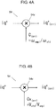
- Fig. 4A is an example of a configuration of torque command corrector 54 executing the above correction.
- torque command corrector 54 is provided as a torque correction means in the exemplary embodiment to correct torque command iq* output from speed controller 53, using correction torque coefficient C (crr) .
- This correction of torque command (q-axis current command) eliminates torque variation due to individual differences of motors and enables to keep a fixed torque constant.
- the maximum speed in the unloaded state is measured in advance by applying a predetermined voltage to a motor coil of the reference motor with known torque constant as a standard motor. Then, the maximum speed in the unloaded state of all motors is measured under the same conditions in a mass production process.
- Correction torque coefficient C (crr) for correcting torque is then calculated based on that speed and the speed of the standard motor, i.e., ⁇ smpl / ⁇ std , which is a ratio between unloaded speed ⁇ std on applying a predetermined voltage to the motor coil of the standard motor in the unloaded state and unloaded speed ⁇ smpl on applying predetermined voltage to motor coil 47 of synchronous motor 40 in the unloaded state.
- Torque command iq* is multiplied by correction torque coefficient C (crr) to correct the torque constant.
- This method for correcting torque constant in the exemplary embodiment can improve variation in motor torque.
- correction torque coefficient C (crr) based on the maximum unloaded speed measured in the mass production process may be stored in a storage part, such as a memory, for correction by torque command corrector 54.
- correction torque coefficient C (crr) based on unloaded speed when an applied voltage to the motor coil is fixed to be constant.
- correction torque coefficient Cv(crr) based on an applied voltage value when the motor speed is fixed to be constant may be used for correction as the torque correction means.
- correction torque coefficient Cv (crr) is calculated as follows.
- induced voltage constant K std is expressed with Formula 10 below on applying voltage V std to rotate the reference motor at predetermined speed ⁇ a .
- K std V std ⁇ a
- correction torque coefficient Cv (crr) may be V std /V smpl , which is a ratio between voltage V std applied to the motor coil when the reference motor with known torque constant is rotated at a predetermined speed and voltage V smpl applied to motor coil 47 when each brushless motor 100 is rotated at the same predetermined speed in the unloaded state.
- Fig. 4B shows a configuration of torque command corrector 54 when the above correction is executed.
- corrected torque command iq* (crr) which is corrected torque, is used only in current control part 55. However, it may be used in other controller or arithmetic operation.
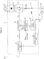
- Fig. 5 is a block diagram of brushless motor 101 equipped with motor control device 11 in the second exemplary embodiment of the present invention.
- Motor control device 11 includes detected torque corrector 33 for correcting detected torque iq in addition to correction of torque command iq*, compared to the first exemplary embodiment in Fig. 1 .
- same reference marks are given to components same as those in Fig. 1 , and detailed description of these components are omitted.
- speed operation part 52 calculates a motor speed based on rotor position information Pr detected by position detector 51. This is sent to speed control part 53 as detected speed ⁇ . Speed control part 53 calculates and outputs torque command iq* such that a deviation between speed command ⁇ * and detected speed ⁇ becomes 0.
- torque converter 32 performs unit conversion of motor current Idet detected by current detector 31 to torque, and outputs it as detected torque iq.
- Detected torque corrector 33 corrects detected torque iq, using correction torque coefficient Cd (crr) , and sends corrected torque iq (crr) obtained to current control part 55.
- detected torque corrector 33 is provided to further correct the detected torque based on detected motor current Idet, so as to keep a fixed torque constant.
- Current control part 55 calculates voltage command Vc that achieves zero deviation between torque command iq* and corrected torque iq (crr) , and outputs it to three-phase inverter 23.
- detected torque iq is corrected to eliminate torque variation due to individual differences of motors and keep a fixed torque constant.
- the motor control device of the present invention can solve torque variation due to individual differences of motors, and is thus applicable to general motor control devices having a speed control part (including current minor loop), such as of a servo motor.
Landscapes
- Engineering & Computer Science (AREA)
- Power Engineering (AREA)
- Databases & Information Systems (AREA)
- Control Of Ac Motors In General (AREA)
- Control Of Motors That Do Not Use Commutators (AREA)
Description
- The present invention relates to motor control devices for controlling a synchronous motor and methods of calculating a correction torque coefficient in the motor control devices.
- In a speed control of a synchronous motor, a conversion coefficient that expresses a relationship between a torque command and actual torque that is actually output from the motor is generally called a torque constant. In general, the torque constant is a fixed value that does not change with speed or current and configures a speed control system. However, the actual torque constant is not always fixed. The torque constant may not be fixed due to an influence of current flowing in the motor and a current control circuit.
- PTL1 discloses a conventional method as a technical measure to cope with it. PTL1 has a means to measure actual output torque relative to the torque command by actually driving the motor, and correct the torque command. PTL1 controls the motor using this corrected torque command, so as to keep a fixed torque constant.
- However, the above conventional method can correct the torque constant according to motor specifications, but cannot correct an influence of individual differences, such as variation in motor production and variation in characteristic of electronic components in a drive circuit.
- The rotating electric machine control device disclosed in
WO 2010/116769 A1 comprises a power converter for driving a rotating electric machine, a DC voltage detection means for detecting a DC voltage applied to the power converter, and a control unit for controlling the operation of the power converter. The control unit includes a terminal voltage fixing means that calculates the terminal voltage of the rotating electric machine on the basis of the DC voltage detected by the DC voltage detection means and d-axis and q-axis voltage commands from a voltage command calculation means and performs control for outputting a d-axis current correction value for correcting a d-axis current command so that the calculated terminal voltage matches a terminal voltage command that is a preset control target value, thereby maintaining the terminal voltage to be constant. -
JP 2008 220155 A - PTL1 Japanese Patent Unexamined Publication No.
H11-191990 - The invention is defined by the appended claims.
- A motor control device according to an exemplary embodiment of the present invention includes a speed control part for controlling a motor rotation speed, and a torque correction means for suppressing variation in torque constant due to individual differences of motors. This eliminates influence of torque variation in individual motors and thus achieves high-precision torque control.
-
-
Fig. 1 is a block diagram of a brushless motor equipped with a motor control device in accordance with a first exemplary embodiment of the present invention. -
Fig. 2 is an example of structure of a synchronous motor in the brushless motor in accordance with the first exemplary embodiment of the present invention. -
Fig. 3 illustrates a relationship between speed and torque of the brushless motor. -
Fig. 4A is an example of a configuration of a torque command corrector in the brushless motor in accordance with the first exemplary embodiment of the present invention. -
Fig. 4B is an example of another configuration of the torque command corrector in the brushless motor in accordance with the first exemplary embodiment of the present invention. -
Fig. 5 is a block diagram of a brushless motor equipped with a motor control device in accordance with a second exemplary embodiment of the present invention. - Exemplary embodiments of the present invention are described below with reference to drawings. The exemplary embodiments described herein are illustrative and not restrictive.
-
Fig. 1 is a block diagram ofbrushless motor 100 equipped withmotor control device 10 in the first exemplary embodiment of the present invention. - As shown in
Fig. 1 ,brushless motor 100 in the exemplary embodiment includesmotor control device 10 andsynchronous motor 40.Synchronous motor 40, which is a motor in the exemplary embodiment, rotates by applying current and drivingsynchronous motor 40 withmotor control device 10. - In
motor control device 10 shown inFig. 1 , rectifyingcircuit 21 rectifies AC voltage fromAC power source 20 to DC voltage. This is then smoothed by smoothingcapacitor 22. Then, the DC voltage is supplied to three-phase inverter 23 inmotor control device 10. Three-phase inverter 23 converts supplied DV voltage to required AC voltage. A drive voltage of this AC voltage is supplied tosynchronous motor 40 including a permanent magnet. In this way, three-phasesynchronous motor 40 having U phase, V phase, and W phase shifted by 120 degrees to each other is driven in the exemplary embodiment. -
Fig. 2 is an example of a structure ofsynchronous motor 40 in the exemplary embodiment. As shown inFig. 2 ,synchronous motor 40 includesrotor 41 andstator 45.Rotor 41 holdspermanent magnet 43 centering onshaft 42. Stator 45 is configured by windingmotor coil 40 aroundstator core 46. - In addition, in the exemplary embodiment,
brushless motor 100 has built-incircuit components 48p that function asmotor control device 10 insynchronous motor 40. Thesecircuit components 48p are mounted oncircuit board 48b. For example, a switchingelement configuring inverter 23 is mounted oncircuit board 48b. Still more,position detector 51 for detecting a rotating position ofrotor 41 is disposed facingpermanent magnet 43 ofrotor 41. In this structure, three-phase AC voltage frominverter 23 is applied tomotor coil 47 of each phase to energizing and drivemotor coils 47, androtor 41 rotates while being rotatably supported by bearing 44. - In
brushless motor 100 as configured above,motor control device 10 includescurrent detector 31,torque converter 32,speed operation part 52,speed control part 53,torque command corrector 54, andcurrent control part 55 in the exemplary embodiment shown inFig. 1 , in addition toinverter 23 described above, so as to control the rotation ofrotor 41. Still more,motor control device 10 receives rotor position information Pr indicating the rotor position fromposition detector 51. Furthermore,motor control device 10 receives speed command ω* for controlling the rotation speed typically from an external controller, as a command for controlling the rotation ofsynchronous motor 40. - Next, in
motor control device 10 inFig. 1 ,speed operation part 52 calculates a motor speed based on rotor position information Pr detected byposition detector 51 typically by differential operation. This is informed tospeed control part 53 as detected speed ω.Speed control part 53 calculates and outputs torque command iq* that makes deviation between speed command ω* and detected speed ω zero. In other words, the speed control part calculates torque command iq* based on the deviation between speed command ω* and detected speed ω. Torquecommand corrector 54 corrects the torque command by multiplying torque command iq* output fromspeed control part 53 by correction torque coefficient C(crr), and sends corrected torque command iq*(crr) obtained tocurrent control part 55. In the exemplary embodiment,torque command corrector 54 is provided to further correct the torque command based on speed deviation, so as to keep a fixed torque constant. In other words, the exemplary embodiment includes thistorque command corrector 54 as a torque correction means for making corrections to suppress variation in torque constant due to individual differences of motors. -
Current detector 31 detects current flowing when drive voltage Vdr, which is AC drive voltage, is applied tomotor coil 47, and outputs it as motor current Idet totorque converter 32.Torque converter 32 performs unit conversion of motor current Idet detected bycurrent detector 31 to torque, and outputs it as detected torque iq tocurrent control part 55.Current control part 55 calculates voltage command Vc such that deviation between torque command iq*(crr) after correction and detected torque iq becomes zero, and outputs it to three-phase inverter 23. In other words,current control part 55 generates voltage command Vc for driving motor coils 47 ofsynchronous motor 40 based on corrected torque command iq*(crr) and detected motor current Idet. Then,inverter 23 generates drive voltage Vdr based on voltage command Vc, and generated drive voltage Vdr is applied tomotor coil 47. - Next, the structure and operation of aforementioned
torque command corrector 54 are further detailed. - As is known by a d-q axis in motor vector control, the d axis is an axis in a magnetic flux direction of
permanent magnet 43 ofrotor 41 inbrushless motor 100, and the q axis is an axis whose phase is advanced for 90 degrees in the rotating direction from the d axis. When current in the d axis is d-axis current id, current in the q axis is q-axis current iq, d-axis inductance ofmotor coil 47 is Ld, q-axis inductance is Lq, induced voltage constant of synchronous motor is Ke, and the number of pole pairs is Pn; torque T ofbrushless motor 100 is expressed withFormula 1 below.
Formula 1
- One of the most popular control methods that have been employed in brushless motors is the id = 0 control to keep the d-axis current at 0. In this case, a current vector moves on the q axis according to the load state. It is apparent from
Formula 1 that reluctance torque Tr = 0 when d-axis current id = 0. Generated torque thus becomes only magnet torque Tm. In this case,Formula 1 is transformed to Formula 2 below. It is apparent from Formula 2 that the torque is proportional only to q-axis current iq. Accordingly, linear control of torque becomes easy.
Formula 2
-
Fig. 3 shows relationship of speed and torque ofbrushless motor 100. When applied voltage V is applied tomotor coil 47 ofbrushless motor 100, motor speed ωo in the unloaded state is expressed with Formula 3 below.
Formula 3
- Formula 3 can be transformed to obtain induced voltage constant Ke in Formula 4 below.
Formula 4
- On the other hand, torque Tstd of a reference motor whose induced voltage constant Kstd is already known is expressed with Formula 5 below based on Formula 2.
Formula 5
- When torque Tsmpl and induced voltage constant Ksmpl of a mass-produced motor are assigned to Formula 5, Formula 6 below is obtained.
Formula 6
- Based on Formula 4, when ωstd is unloaded speed on applying voltage Va to the reference motor, induced voltage constant Kstd is expressed with Formula 7 below.
Formula 7
- When ωsmpl is unloaded speed on applying voltage Va to a mass-produced motor under the same conditions, induced voltage constant Ksmpl is expressed with Formula 8 below.
Formula 8
- Following Formula 9 is obtained by assigning Formulae 7 and 8 to Formula 6.
Formula 9
- It is apparent from the above that a torque value same as that of the reference motor is obtained by multiplying q-axis current iq by ωsmpl/ωstd in the mass-produced motor. Here, correction torque coefficient C(crr) of
torque command corrector 54 is this ωsmpl/ωstd, which is a ratio between unloaded speed ωsmpl of the mass-produced motor and unloaded speed ωstd of the reference motor. -
Fig. 4A is an example of a configuration oftorque command corrector 54 executing the above correction. As shown inFig. 4A ,torque command corrector 54 includesmultiplier 54x, and multiplies input torque command iq* by correction torque coefficient C(crr) = ωsmpl/ωstd to output a multiplication result as corrected torque command iq*(crr). - As described above,
torque command corrector 54 is provided as a torque correction means in the exemplary embodiment to correct torque command iq* output fromspeed controller 53, using correction torque coefficient C(crr). This correction of torque command (q-axis current command) eliminates torque variation due to individual differences of motors and enables to keep a fixed torque constant. - More specifically, the maximum speed in the unloaded state is measured in advance by applying a predetermined voltage to a motor coil of the reference motor with known torque constant as a standard motor. Then, the maximum speed in the unloaded state of all motors is measured under the same conditions in a mass production process. Correction torque coefficient C(crr) for correcting torque is then calculated based on that speed and the speed of the standard motor, i.e., ωsmpl/ωstd, which is a ratio between unloaded speed ωstd on applying a predetermined voltage to the motor coil of the standard motor in the unloaded state and unloaded speed ωsmpl on applying predetermined voltage to
motor coil 47 ofsynchronous motor 40 in the unloaded state. Torque command iq* is multiplied by correction torque coefficient C(crr) to correct the torque constant. This method for correcting torque constant in the exemplary embodiment can improve variation in motor torque. As for specific example, correction torque coefficient C(crr) based on the maximum unloaded speed measured in the mass production process may be stored in a storage part, such as a memory, for correction bytorque command corrector 54. - The above description refers to a correction method using correction torque coefficient C(crr) based on unloaded speed when an applied voltage to the motor coil is fixed to be constant. However, correction torque coefficient Cv(crr) based on an applied voltage value when the motor speed is fixed to be constant may be used for correction as the torque correction means.
- In this case, correction torque coefficient Cv(crr) is calculated as follows.
- From Formula 4, induced voltage constant Kstd is expressed with
Formula 10 below on applying voltage Vstd to rotate the reference motor at predetermined speed ωa.
Formula 10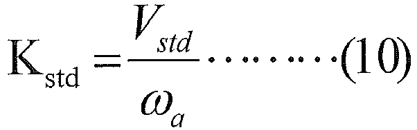
- On applying voltage Vsmpl to rotate the mass-produced motor at predetermined speed ωa under the same conditions, induced voltage constant Ksmpl is expressed with
Formula 11 below.
Formula 11
- By assigning
Formulae
Formula 12
- As described above, torque variation due to individual differences of motors can be corrected by multiplying torque command (q-axis current command) iq* of the mass-produced motor by correction torque coefficient Cv(crr), which is Vstd/Vsmpl. In other words, correction torque coefficient Cv(crr) may be Vstd/Vsmpl, which is a ratio between voltage Vstd applied to the motor coil when the reference motor with known torque constant is rotated at a predetermined speed and voltage Vsmpl applied to
motor coil 47 when eachbrushless motor 100 is rotated at the same predetermined speed in the unloaded state. -
Fig. 4B shows a configuration oftorque command corrector 54 when the above correction is executed. As shown inFig. 4B ,torque command corrector 54 includesmultiplier 54x and multiplies input torque command iq* by correction torque coefficient Cv(crr) = Vstd/Vsmpl to output a multiplication result as corrected torque command iq*(crr). - In the exemplary embodiment, corrected torque command iq*(crr), which is corrected torque, is used only in
current control part 55. However, it may be used in other controller or arithmetic operation. -
Fig. 5 is a block diagram ofbrushless motor 101 equipped withmotor control device 11 in the second exemplary embodiment of the present invention.Motor control device 11 includes detectedtorque corrector 33 for correcting detected torque iq in addition to correction of torque command iq*, compared to the first exemplary embodiment inFig. 1 . InFig. 5 , same reference marks are given to components same as those inFig. 1 , and detailed description of these components are omitted. - In
Fig. 5 ,speed operation part 52 calculates a motor speed based on rotor position information Pr detected byposition detector 51. This is sent to speedcontrol part 53 as detected speed ω.Speed control part 53 calculates and outputs torque command iq* such that a deviation between speed command ω* and detected speed ω becomes 0. - On the other hand,
torque converter 32 performs unit conversion of motor current Idet detected bycurrent detector 31 to torque, and outputs it as detected torque iq. Detectedtorque corrector 33 corrects detected torque iq, using correction torque coefficient Cd(crr), and sends corrected torque iq(crr) obtained tocurrent control part 55. In the exemplary embodiment, detectedtorque corrector 33 is provided to further correct the detected torque based on detected motor current Idet, so as to keep a fixed torque constant. -
Current control part 55 calculates voltage command Vc that achieves zero deviation between torque command iq* and corrected torque iq(crr), and outputs it to three-phase inverter 23. - Here, with respect to correction by detected
torque corrector 33, a torque value same as that of the reference motor is achieved by multiplying detected torque (detected q-axis current) by correction torque coefficient C(crr) = ωsmpl/ωstd, as in Formula 9 in the first exemplary embodiment. In the exemplary embodiment, detected torque iq is corrected to eliminate torque variation due to individual differences of motors and keep a fixed torque constant. - In the exemplary embodiment, torque variation due to individual differences of motors can also be corrected by multiplying detected torque (detected q-axis current) by corrected torque coefficient Cdv(crr) = Vstd/Vsmpl, as in Formula 12 in the first exemplary embodiment.
- As described above, the motor control device of the present invention can solve torque variation due to individual differences of motors, and is thus applicable to general motor control devices having a speed control part (including current minor loop), such as of a servo motor.
-
- 10, 11
- Motor control device
- 20
- AC power source
- 21
- Rectifying circuit
- 22
- Smoothing capacitor
- 23
- Inverter
- 31
- Current detector
- 32
- Torque converter
- 33
- Detected torque corrector
- 40
- Synchronous motor
- 41
- Rotor
- 42
- Shaft
- 43
- Permanent magnet
- 44
- Bearing
- 45
- Stator
- 46
- Stator core
- 47
- Motor coil
- 48b
- Circuit board
- 48p
- Circuit component
- 51
- Position detector
- 52
- Speed operation part
- 53
- Speed control part
- 54
- Torque command corrector
- 54x
- Multiplier
- 55
- Current control part
- 100, 101
- Brushless motor
Claims (8)
- A motor control device (10) at least including a speed control part (53) for controlling a rotation speed of a synchronous motor (40) with built-in electronic components in a drive circuit, the motor control device (10) comprising a torque correction means for making a correction to suppress a variation in a conversion coefficient expressing a relationship between a torque command and actual torque that is output from the motor (40) due to an individual difference of the motor (40), such as a variation in motor production and variation in characteristics of the electronic components in a drive circuit, characterized in that the torque correction means is configured to correct the conversion coefficient based on a maximum unloaded speed when an applied voltage is fixed or based on a motor applied voltage when a speed of the motor is fixed.
- The motor control device (10) of claim 1, wherein the torque correction means is used for correcting a torque command output from the speed control part (53).
- The motor control device (10) of claim 1, wherein the torque correction means is used for correcting a detected current or a detected torque of the motor (40).
- The motor control device (10) of claim 1, comprising:the speed control part (53) for calculating a torque command based on a deviation between a speed command and a detected speed;a torque command corrector (54) as the torque correction means for making a correction by multiplying the torque command by a correction torque coefficient and outputting a result of the multiplication as a corrected torque command;a current control part (55) for generating a voltage command for driving a motor coil of the motor based on the corrected torque command and a detected motor current; andan inverter (23) for generating a drive voltage for energizing and driving the motor coil based on the voltage command from the current control part.
- The motor control device (10) of claim 6, wherein the correction torque coefficient is a ratio in an unloaded state between an unloaded speed when a predetermined voltage is applied to a motor coil of a reference motor with a known conversion coefficient and an unloaded speed when the predetermined voltage is applied to the motor coil of the motor (40).
- The motor control device (10) of claim 6, wherein the correction torque coefficient is a ratio in an unloaded state between a voltage applied to a motor coil when a reference motor with a known conversion coefficient is rotated at a predetermined speed and a voltage applied to the motor coil when the motor (40) is rotated at the predetermined speed.
- A method for controlling a rotation speed of a synchronous motor (40) with built-in electronic components in a drive circuit, the method comprising:making a correction to suppress a variation in a conversion coefficient expressing a relationship between a torque command and actual torque that is output from the motor (40) due to an individual difference of the motor (40) such as variation in motor production and variation in characteristics of the electronic components in a drive circuit, characterized in thatthe correction of the conversion coefficient is based on a maximum unloaded speed when an applied voltage is fixed or based on a motor applied voltage when a speed of the motor (40) is fixed.
- The method of claim 7, further comprising:measuring a maximum unloaded speed of a reference motor with the torque constant already known as a standard motor when a predetermined voltage is applied to a motor coil;measuring a maximum unloaded speed of all motors in a mass production process under a same condition;calculating a ratio between an unloaded speed when the predetermined voltage is applied to the motor coil of the reference motor in the unloaded state and an unloaded speed when the predetermined voltage is applied to the motor coil of the motor in the unloaded state, and setting the ratio as the correction torque coefficient; andmaking a correction by multiplying the torque command by the correction torque coefficient.
Applications Claiming Priority (2)
| Application Number | Priority Date | Filing Date | Title |
|---|---|---|---|
| JP2015013835 | 2015-01-28 | ||
| PCT/JP2016/000363 WO2016121373A1 (en) | 2015-01-28 | 2016-01-26 | Motor control device, and method for correcting torque constant in such motor control device |
Publications (3)
| Publication Number | Publication Date |
|---|---|
| EP3157162A1 EP3157162A1 (en) | 2017-04-19 |
| EP3157162A4 EP3157162A4 (en) | 2017-08-16 |
| EP3157162B1 true EP3157162B1 (en) | 2020-07-15 |
Family
ID=56542995
Family Applications (1)
| Application Number | Title | Priority Date | Filing Date |
|---|---|---|---|
| EP16742977.8A Active EP3157162B1 (en) | 2015-01-28 | 2016-01-26 | Motor control device, and method for correcting torque constant in such motor control device |
Country Status (5)
| Country | Link |
|---|---|
| US (2) | US10270377B2 (en) |
| EP (1) | EP3157162B1 (en) |
| JP (1) | JP6667076B2 (en) |
| CN (1) | CN106537760B (en) |
| WO (1) | WO2016121373A1 (en) |
Families Citing this family (10)
| Publication number | Priority date | Publication date | Assignee | Title |
|---|---|---|---|---|
| US11370307B2 (en) * | 2016-06-30 | 2022-06-28 | Borg Warner Gateshead Limited | Method and apparatus for controlling an electric motor |
| GB2551822B (en) | 2016-06-30 | 2018-08-22 | Sevcon Ltd | Methods and apparatus for controlling an electric motor |
| CN106208833B (en) * | 2016-09-23 | 2019-09-24 | 北京乾勤科技发展有限公司 | DC brushless motor most Daheng's torque control method |
| JP6426782B2 (en) * | 2017-03-14 | 2018-11-21 | ファナック株式会社 | Servo motor control device for controlling servo motor and servo motor control system including the same |
| JP2018182975A (en) * | 2017-04-19 | 2018-11-15 | パナソニックIpマネジメント株式会社 | Compressor motor drive |
| JP7050624B2 (en) * | 2018-08-24 | 2022-04-08 | 日立Astemo株式会社 | Motor control device and electric brake device equipped with it |
| CN109818541B (en) * | 2019-03-13 | 2020-10-02 | 东南大学 | A memory motor winding multiplexing control method and system for flux linkage observation |
| EP4048544B1 (en) * | 2019-10-23 | 2024-03-13 | Eldor Corporation S.p.A. | A drive system for a hybrid or electric vehicle |
| CN115008422A (en) | 2021-03-03 | 2022-09-06 | 创科无线普通合伙 | Control system for normally open power tool |
| WO2023067682A1 (en) * | 2021-10-19 | 2023-04-27 | ファナック株式会社 | Servomotor control device |
Family Cites Families (23)
| Publication number | Priority date | Publication date | Assignee | Title |
|---|---|---|---|---|
| JPS5869497A (en) | 1981-10-22 | 1983-04-25 | Fuji Electric Co Ltd | Motor control system by current pwm inverter |
| JP3578900B2 (en) | 1997-12-25 | 2004-10-20 | ファナック株式会社 | Servo motor control device |
| JP3755054B2 (en) * | 1998-02-27 | 2006-03-15 | 三菱電機株式会社 | Synchronous control device |
| JP2001278085A (en) * | 2000-03-30 | 2001-10-10 | Toyoda Mach Works Ltd | Electric power steering |
| JP4066914B2 (en) * | 2003-08-25 | 2008-03-26 | 富士電機システムズ株式会社 | Motor drive control device |
| JP4538786B2 (en) * | 2004-04-09 | 2010-09-08 | 株式会社安川電機 | Motor control device |
| JP2006340454A (en) * | 2005-05-31 | 2006-12-14 | Mitsubishi Electric Corp | Motor control device |
| JP2006342454A (en) | 2005-06-08 | 2006-12-21 | Canon Electronics Inc | Inkjet printing method, fabric for inkjet printing and printer for inkjet printing |
| JP5453714B2 (en) * | 2007-02-08 | 2014-03-26 | 株式会社ジェイテクト | Motor control device and electric power steering device |
| US7889978B2 (en) * | 2007-02-08 | 2011-02-15 | Jtekt Corporation | Motor controller and electric power steering system |
| JP5187172B2 (en) * | 2008-08-06 | 2013-04-24 | 株式会社安川電機 | Motor control device, torque ripple correction method thereof, and motor control system |
| JP5509677B2 (en) * | 2008-09-24 | 2014-06-04 | セイコーエプソン株式会社 | Device, method, motor, motor-mounted device, and computer program for calculating characteristics of motor |
| KR101171659B1 (en) * | 2008-10-29 | 2012-08-07 | 미쓰비시덴키 가부시키가이샤 | Control apparatus for permanent magnet synchronous motor |
| JP2010130853A (en) * | 2008-11-28 | 2010-06-10 | Yaskawa Electric Corp | Motor control device and motor winding resistance value change detection method |
| JP5196269B2 (en) * | 2009-03-04 | 2013-05-15 | 本田技研工業株式会社 | Electric motor control device |
| WO2010116769A1 (en) | 2009-04-10 | 2010-10-14 | 三菱電機株式会社 | Rotating electric machine control device |
| JP5175887B2 (en) * | 2010-03-23 | 2013-04-03 | 株式会社東芝 | Motor control device and electrical equipment |
| JP5174205B2 (en) | 2011-04-01 | 2013-04-03 | ファナック株式会社 | Detection device for detecting magnetic pole position of synchronous motor and control device including the same |
| DE102013200248A1 (en) * | 2013-01-10 | 2014-07-24 | Robert Bosch Gmbh | Method for designing control transmitter system with electric motor for use in e.g. seat adjuster in motor vehicle, involves adjusting controlling of electric motor for each function of applications, using configuration parameter |
| JP5620527B2 (en) * | 2013-02-05 | 2014-11-05 | 山洋電気株式会社 | Motor control device |
| US9376025B2 (en) | 2013-02-06 | 2016-06-28 | Lg Electronics Inc. | Charging apparatus and electric vehicle including the same |
| JP2014204489A (en) * | 2013-04-02 | 2014-10-27 | 三菱電機株式会社 | Rotary machine control device |
| JP5800933B2 (en) * | 2014-02-28 | 2015-10-28 | ファナック株式会社 | Motor control device for controlling synchronous motor |
-
2016
- 2016-01-26 EP EP16742977.8A patent/EP3157162B1/en active Active
- 2016-01-26 CN CN201680002103.9A patent/CN106537760B/en active Active
- 2016-01-26 WO PCT/JP2016/000363 patent/WO2016121373A1/en not_active Ceased
- 2016-01-26 JP JP2016571861A patent/JP6667076B2/en active Active
- 2016-01-26 US US15/325,309 patent/US10270377B2/en active Active
-
2019
- 2019-02-27 US US16/287,601 patent/US10469013B2/en active Active
Non-Patent Citations (1)
| Title |
|---|
| None * |
Also Published As
| Publication number | Publication date |
|---|---|
| US10270377B2 (en) | 2019-04-23 |
| EP3157162A1 (en) | 2017-04-19 |
| JPWO2016121373A1 (en) | 2017-11-09 |
| JP6667076B2 (en) | 2020-03-18 |
| US20170163194A1 (en) | 2017-06-08 |
| US10469013B2 (en) | 2019-11-05 |
| WO2016121373A1 (en) | 2016-08-04 |
| EP3157162A4 (en) | 2017-08-16 |
| CN106537760A (en) | 2017-03-22 |
| CN106537760B (en) | 2020-03-31 |
| US20190199257A1 (en) | 2019-06-27 |
Similar Documents
| Publication | Publication Date | Title |
|---|---|---|
| US10469013B2 (en) | Motor control device, and method for correcting torque constant in such motor control device | |
| JP5130031B2 (en) | Position sensorless control device for permanent magnet motor | |
| JP6008264B2 (en) | Magnetic pole position detection device for permanent magnet type synchronous motor | |
| US9825579B2 (en) | Temperature estimating apparatus for synchronous motor | |
| EP2020743B1 (en) | Sensorless controlling apparatus for controlling a brushless motor | |
| US20090322262A1 (en) | Controller For Permanent Magnet Synchronous Motor and Motor Control System | |
| JP6580899B2 (en) | Drive system and inverter device | |
| US20070222404A1 (en) | Controller for motor | |
| EP2945280A2 (en) | Apparatus for controlling induction machine | |
| JP5267848B2 (en) | Motor control device | |
| JP5416183B2 (en) | Control device for permanent magnet synchronous motor | |
| JP2001186800A (en) | Control device for permanent magnet synchronous motor | |
| JP5744151B2 (en) | Electric motor driving apparatus and electric motor driving method | |
| JP2002078390A (en) | Motor control device | |
| JP6108114B2 (en) | Control device for permanent magnet type synchronous motor | |
| JP4687104B2 (en) | Control device and method for permanent magnet type rotary motor | |
| JP5228435B2 (en) | Inverter control device and control method thereof | |
| JP7567532B2 (en) | Highly efficient operation control device and method for a permanent magnet synchronous motor | |
| JP2003339193A (en) | Driver of stepping motor | |
| JP2001224195A (en) | Control method of permanent magnet synchronous motor | |
| CN107276480B (en) | Equipment for correcting current benchmark | |
| KR20250122202A (en) | Apparatus and method for controlling motor driving | |
| JP5228629B2 (en) | AC motor inverter device and motor current control method thereof | |
| HK1093384B (en) | Vector controller of induction motor | |
| HK1093384A1 (en) | Vector controller of induction motor |
Legal Events
| Date | Code | Title | Description |
|---|---|---|---|
| STAA | Information on the status of an ep patent application or granted ep patent |
Free format text: STATUS: THE INTERNATIONAL PUBLICATION HAS BEEN MADE |
|
| PUAI | Public reference made under article 153(3) epc to a published international application that has entered the european phase |
Free format text: ORIGINAL CODE: 0009012 |
|
| STAA | Information on the status of an ep patent application or granted ep patent |
Free format text: STATUS: REQUEST FOR EXAMINATION WAS MADE |
|
| 17P | Request for examination filed |
Effective date: 20161121 |
|
| AK | Designated contracting states |
Kind code of ref document: A1 Designated state(s): AL AT BE BG CH CY CZ DE DK EE ES FI FR GB GR HR HU IE IS IT LI LT LU LV MC MK MT NL NO PL PT RO RS SE SI SK SM TR |
|
| AX | Request for extension of the european patent |
Extension state: BA ME |
|
| A4 | Supplementary search report drawn up and despatched |
Effective date: 20170713 |
|
| RIC1 | Information provided on ipc code assigned before grant |
Ipc: H02P 21/20 20160101ALI20170707BHEP Ipc: H02P 6/06 20060101ALI20170707BHEP Ipc: H02P 21/00 20160101AFI20170707BHEP Ipc: H02P 27/04 20160101ALI20170707BHEP Ipc: H02P 23/00 20160101ALI20170707BHEP |
|
| DAV | Request for validation of the european patent (deleted) | ||
| DAX | Request for extension of the european patent (deleted) | ||
| GRAP | Despatch of communication of intention to grant a patent |
Free format text: ORIGINAL CODE: EPIDOSNIGR1 |
|
| STAA | Information on the status of an ep patent application or granted ep patent |
Free format text: STATUS: GRANT OF PATENT IS INTENDED |
|
| INTG | Intention to grant announced |
Effective date: 20200331 |
|
| GRAS | Grant fee paid |
Free format text: ORIGINAL CODE: EPIDOSNIGR3 |
|
| GRAA | (expected) grant |
Free format text: ORIGINAL CODE: 0009210 |
|
| STAA | Information on the status of an ep patent application or granted ep patent |
Free format text: STATUS: THE PATENT HAS BEEN GRANTED |
|
| AK | Designated contracting states |
Kind code of ref document: B1 Designated state(s): AL AT BE BG CH CY CZ DE DK EE ES FI FR GB GR HR HU IE IS IT LI LT LU LV MC MK MT NL NO PL PT RO RS SE SI SK SM TR |
|
| REG | Reference to a national code |
Ref country code: GB Ref legal event code: FG4D Ref country code: CH Ref legal event code: EP |
|
| REG | Reference to a national code |
Ref country code: IE Ref legal event code: FG4D |
|
| REG | Reference to a national code |
Ref country code: DE Ref legal event code: R096 Ref document number: 602016039967 Country of ref document: DE |
|
| REG | Reference to a national code |
Ref country code: AT Ref legal event code: REF Ref document number: 1292094 Country of ref document: AT Kind code of ref document: T Effective date: 20200815 |
|
| REG | Reference to a national code |
Ref country code: LT Ref legal event code: MG4D |
|
| REG | Reference to a national code |
Ref country code: AT Ref legal event code: MK05 Ref document number: 1292094 Country of ref document: AT Kind code of ref document: T Effective date: 20200715 |
|
| REG | Reference to a national code |
Ref country code: NL Ref legal event code: MP Effective date: 20200715 |
|
| PG25 | Lapsed in a contracting state [announced via postgrant information from national office to epo] |
Ref country code: SE Free format text: LAPSE BECAUSE OF FAILURE TO SUBMIT A TRANSLATION OF THE DESCRIPTION OR TO PAY THE FEE WITHIN THE PRESCRIBED TIME-LIMIT Effective date: 20200715 Ref country code: GR Free format text: LAPSE BECAUSE OF FAILURE TO SUBMIT A TRANSLATION OF THE DESCRIPTION OR TO PAY THE FEE WITHIN THE PRESCRIBED TIME-LIMIT Effective date: 20201016 Ref country code: FI Free format text: LAPSE BECAUSE OF FAILURE TO SUBMIT A TRANSLATION OF THE DESCRIPTION OR TO PAY THE FEE WITHIN THE PRESCRIBED TIME-LIMIT Effective date: 20200715 Ref country code: NO Free format text: LAPSE BECAUSE OF FAILURE TO SUBMIT A TRANSLATION OF THE DESCRIPTION OR TO PAY THE FEE WITHIN THE PRESCRIBED TIME-LIMIT Effective date: 20201015 Ref country code: AT Free format text: LAPSE BECAUSE OF FAILURE TO SUBMIT A TRANSLATION OF THE DESCRIPTION OR TO PAY THE FEE WITHIN THE PRESCRIBED TIME-LIMIT Effective date: 20200715 Ref country code: LT Free format text: LAPSE BECAUSE OF FAILURE TO SUBMIT A TRANSLATION OF THE DESCRIPTION OR TO PAY THE FEE WITHIN THE PRESCRIBED TIME-LIMIT Effective date: 20200715 Ref country code: PT Free format text: LAPSE BECAUSE OF FAILURE TO SUBMIT A TRANSLATION OF THE DESCRIPTION OR TO PAY THE FEE WITHIN THE PRESCRIBED TIME-LIMIT Effective date: 20201116 Ref country code: HR Free format text: LAPSE BECAUSE OF FAILURE TO SUBMIT A TRANSLATION OF THE DESCRIPTION OR TO PAY THE FEE WITHIN THE PRESCRIBED TIME-LIMIT Effective date: 20200715 Ref country code: BG Free format text: LAPSE BECAUSE OF FAILURE TO SUBMIT A TRANSLATION OF THE DESCRIPTION OR TO PAY THE FEE WITHIN THE PRESCRIBED TIME-LIMIT Effective date: 20201015 Ref country code: ES Free format text: LAPSE BECAUSE OF FAILURE TO SUBMIT A TRANSLATION OF THE DESCRIPTION OR TO PAY THE FEE WITHIN THE PRESCRIBED TIME-LIMIT Effective date: 20200715 |
|
| PG25 | Lapsed in a contracting state [announced via postgrant information from national office to epo] |
Ref country code: IS Free format text: LAPSE BECAUSE OF FAILURE TO SUBMIT A TRANSLATION OF THE DESCRIPTION OR TO PAY THE FEE WITHIN THE PRESCRIBED TIME-LIMIT Effective date: 20201115 Ref country code: PL Free format text: LAPSE BECAUSE OF FAILURE TO SUBMIT A TRANSLATION OF THE DESCRIPTION OR TO PAY THE FEE WITHIN THE PRESCRIBED TIME-LIMIT Effective date: 20200715 Ref country code: LV Free format text: LAPSE BECAUSE OF FAILURE TO SUBMIT A TRANSLATION OF THE DESCRIPTION OR TO PAY THE FEE WITHIN THE PRESCRIBED TIME-LIMIT Effective date: 20200715 Ref country code: RS Free format text: LAPSE BECAUSE OF FAILURE TO SUBMIT A TRANSLATION OF THE DESCRIPTION OR TO PAY THE FEE WITHIN THE PRESCRIBED TIME-LIMIT Effective date: 20200715 |
|
| PG25 | Lapsed in a contracting state [announced via postgrant information from national office to epo] |
Ref country code: NL Free format text: LAPSE BECAUSE OF FAILURE TO SUBMIT A TRANSLATION OF THE DESCRIPTION OR TO PAY THE FEE WITHIN THE PRESCRIBED TIME-LIMIT Effective date: 20200715 |
|
| REG | Reference to a national code |
Ref country code: DE Ref legal event code: R097 Ref document number: 602016039967 Country of ref document: DE |
|
| PG25 | Lapsed in a contracting state [announced via postgrant information from national office to epo] |
Ref country code: DK Free format text: LAPSE BECAUSE OF FAILURE TO SUBMIT A TRANSLATION OF THE DESCRIPTION OR TO PAY THE FEE WITHIN THE PRESCRIBED TIME-LIMIT Effective date: 20200715 Ref country code: CZ Free format text: LAPSE BECAUSE OF FAILURE TO SUBMIT A TRANSLATION OF THE DESCRIPTION OR TO PAY THE FEE WITHIN THE PRESCRIBED TIME-LIMIT Effective date: 20200715 Ref country code: SM Free format text: LAPSE BECAUSE OF FAILURE TO SUBMIT A TRANSLATION OF THE DESCRIPTION OR TO PAY THE FEE WITHIN THE PRESCRIBED TIME-LIMIT Effective date: 20200715 Ref country code: RO Free format text: LAPSE BECAUSE OF FAILURE TO SUBMIT A TRANSLATION OF THE DESCRIPTION OR TO PAY THE FEE WITHIN THE PRESCRIBED TIME-LIMIT Effective date: 20200715 Ref country code: EE Free format text: LAPSE BECAUSE OF FAILURE TO SUBMIT A TRANSLATION OF THE DESCRIPTION OR TO PAY THE FEE WITHIN THE PRESCRIBED TIME-LIMIT Effective date: 20200715 Ref country code: IT Free format text: LAPSE BECAUSE OF FAILURE TO SUBMIT A TRANSLATION OF THE DESCRIPTION OR TO PAY THE FEE WITHIN THE PRESCRIBED TIME-LIMIT Effective date: 20200715 |
|
| PLBE | No opposition filed within time limit |
Free format text: ORIGINAL CODE: 0009261 |
|
| STAA | Information on the status of an ep patent application or granted ep patent |
Free format text: STATUS: NO OPPOSITION FILED WITHIN TIME LIMIT |
|
| PG25 | Lapsed in a contracting state [announced via postgrant information from national office to epo] |
Ref country code: AL Free format text: LAPSE BECAUSE OF FAILURE TO SUBMIT A TRANSLATION OF THE DESCRIPTION OR TO PAY THE FEE WITHIN THE PRESCRIBED TIME-LIMIT Effective date: 20200715 |
|
| 26N | No opposition filed |
Effective date: 20210416 |
|
| PG25 | Lapsed in a contracting state [announced via postgrant information from national office to epo] |
Ref country code: SK Free format text: LAPSE BECAUSE OF FAILURE TO SUBMIT A TRANSLATION OF THE DESCRIPTION OR TO PAY THE FEE WITHIN THE PRESCRIBED TIME-LIMIT Effective date: 20200715 |
|
| PG25 | Lapsed in a contracting state [announced via postgrant information from national office to epo] |
Ref country code: SI Free format text: LAPSE BECAUSE OF FAILURE TO SUBMIT A TRANSLATION OF THE DESCRIPTION OR TO PAY THE FEE WITHIN THE PRESCRIBED TIME-LIMIT Effective date: 20200715 Ref country code: MC Free format text: LAPSE BECAUSE OF FAILURE TO SUBMIT A TRANSLATION OF THE DESCRIPTION OR TO PAY THE FEE WITHIN THE PRESCRIBED TIME-LIMIT Effective date: 20200715 |
|
| REG | Reference to a national code |
Ref country code: CH Ref legal event code: PL |
|
| GBPC | Gb: european patent ceased through non-payment of renewal fee |
Effective date: 20210126 |
|
| PG25 | Lapsed in a contracting state [announced via postgrant information from national office to epo] |
Ref country code: LU Free format text: LAPSE BECAUSE OF NON-PAYMENT OF DUE FEES Effective date: 20210126 |
|
| REG | Reference to a national code |
Ref country code: BE Ref legal event code: MM Effective date: 20210131 |
|
| PG25 | Lapsed in a contracting state [announced via postgrant information from national office to epo] |
Ref country code: FR Free format text: LAPSE BECAUSE OF NON-PAYMENT OF DUE FEES Effective date: 20210131 |
|
| PG25 | Lapsed in a contracting state [announced via postgrant information from national office to epo] |
Ref country code: LI Free format text: LAPSE BECAUSE OF NON-PAYMENT OF DUE FEES Effective date: 20210131 Ref country code: GB Free format text: LAPSE BECAUSE OF NON-PAYMENT OF DUE FEES Effective date: 20210126 Ref country code: CH Free format text: LAPSE BECAUSE OF NON-PAYMENT OF DUE FEES Effective date: 20210131 |
|
| PG25 | Lapsed in a contracting state [announced via postgrant information from national office to epo] |
Ref country code: IE Free format text: LAPSE BECAUSE OF NON-PAYMENT OF DUE FEES Effective date: 20210126 |
|
| PG25 | Lapsed in a contracting state [announced via postgrant information from national office to epo] |
Ref country code: IS Free format text: LAPSE BECAUSE OF FAILURE TO SUBMIT A TRANSLATION OF THE DESCRIPTION OR TO PAY THE FEE WITHIN THE PRESCRIBED TIME-LIMIT Effective date: 20201115 |
|
| PG25 | Lapsed in a contracting state [announced via postgrant information from national office to epo] |
Ref country code: BE Free format text: LAPSE BECAUSE OF NON-PAYMENT OF DUE FEES Effective date: 20210131 |
|
| PG25 | Lapsed in a contracting state [announced via postgrant information from national office to epo] |
Ref country code: HU Free format text: LAPSE BECAUSE OF FAILURE TO SUBMIT A TRANSLATION OF THE DESCRIPTION OR TO PAY THE FEE WITHIN THE PRESCRIBED TIME-LIMIT; INVALID AB INITIO Effective date: 20160126 |
|
| PG25 | Lapsed in a contracting state [announced via postgrant information from national office to epo] |
Ref country code: CY Free format text: LAPSE BECAUSE OF FAILURE TO SUBMIT A TRANSLATION OF THE DESCRIPTION OR TO PAY THE FEE WITHIN THE PRESCRIBED TIME-LIMIT Effective date: 20200715 |
|
| PG25 | Lapsed in a contracting state [announced via postgrant information from national office to epo] |
Ref country code: MK Free format text: LAPSE BECAUSE OF FAILURE TO SUBMIT A TRANSLATION OF THE DESCRIPTION OR TO PAY THE FEE WITHIN THE PRESCRIBED TIME-LIMIT Effective date: 20200715 |
|
| PG25 | Lapsed in a contracting state [announced via postgrant information from national office to epo] |
Ref country code: MT Free format text: LAPSE BECAUSE OF FAILURE TO SUBMIT A TRANSLATION OF THE DESCRIPTION OR TO PAY THE FEE WITHIN THE PRESCRIBED TIME-LIMIT Effective date: 20200715 |
|
| PG25 | Lapsed in a contracting state [announced via postgrant information from national office to epo] |
Ref country code: TR Free format text: LAPSE BECAUSE OF FAILURE TO SUBMIT A TRANSLATION OF THE DESCRIPTION OR TO PAY THE FEE WITHIN THE PRESCRIBED TIME-LIMIT Effective date: 20200715 |
|
| PGFP | Annual fee paid to national office [announced via postgrant information from national office to epo] |
Ref country code: DE Payment date: 20260121 Year of fee payment: 11 |