EP3156750A1 - Shelf for thermal processing - Google Patents
Shelf for thermal processing Download PDFInfo
- Publication number
- EP3156750A1 EP3156750A1 EP16193671.1A EP16193671A EP3156750A1 EP 3156750 A1 EP3156750 A1 EP 3156750A1 EP 16193671 A EP16193671 A EP 16193671A EP 3156750 A1 EP3156750 A1 EP 3156750A1
- Authority
- EP
- European Patent Office
- Prior art keywords
- board
- shelf
- column
- columns
- projection portion
- Prior art date
- Legal status (The legal status is an assumption and is not a legal conclusion. Google has not performed a legal analysis and makes no representation as to the accuracy of the status listed.)
- Granted
Links
- 125000006850 spacer group Chemical group 0.000 claims description 41
- 238000000034 method Methods 0.000 description 27
- 238000001816 cooling Methods 0.000 description 7
- 238000010438 heat treatment Methods 0.000 description 7
- HBMJWWWQQXIZIP-UHFFFAOYSA-N silicon carbide Chemical compound [Si+]#[C-] HBMJWWWQQXIZIP-UHFFFAOYSA-N 0.000 description 4
- 229910010271 silicon carbide Inorganic materials 0.000 description 4
- 239000000853 adhesive Substances 0.000 description 3
- 230000001070 adhesive effect Effects 0.000 description 3
- 239000000463 material Substances 0.000 description 3
- 238000004519 manufacturing process Methods 0.000 description 2
- 230000002093 peripheral effect Effects 0.000 description 2
- OKTJSMMVPCPJKN-UHFFFAOYSA-N Carbon Chemical compound [C] OKTJSMMVPCPJKN-UHFFFAOYSA-N 0.000 description 1
- 239000004372 Polyvinyl alcohol Substances 0.000 description 1
- 230000004075 alteration Effects 0.000 description 1
- 239000011230 binding agent Substances 0.000 description 1
- 229910052799 carbon Inorganic materials 0.000 description 1
- 239000000919 ceramic Substances 0.000 description 1
- 229910010293 ceramic material Inorganic materials 0.000 description 1
- 238000001125 extrusion Methods 0.000 description 1
- 238000000465 moulding Methods 0.000 description 1
- 229920003023 plastic Polymers 0.000 description 1
- 229920002451 polyvinyl alcohol Polymers 0.000 description 1
- 239000000843 powder Substances 0.000 description 1
- 229910052710 silicon Inorganic materials 0.000 description 1
- 239000010703 silicon Substances 0.000 description 1
- 239000007787 solid Substances 0.000 description 1
- 230000008646 thermal stress Effects 0.000 description 1
- XLYOFNOQVPJJNP-UHFFFAOYSA-N water Substances O XLYOFNOQVPJJNP-UHFFFAOYSA-N 0.000 description 1
Images



Classifications
-
- F—MECHANICAL ENGINEERING; LIGHTING; HEATING; WEAPONS; BLASTING
- F27—FURNACES; KILNS; OVENS; RETORTS
- F27D—DETAILS OR ACCESSORIES OF FURNACES, KILNS, OVENS OR RETORTS, IN SO FAR AS THEY ARE OF KINDS OCCURRING IN MORE THAN ONE KIND OF FURNACE
- F27D5/00—Supports, screens or the like for the charge within the furnace
- F27D5/0006—Composite supporting structures
- F27D5/0012—Modules of the sagger or setter type; Supports built up from them
-
- F—MECHANICAL ENGINEERING; LIGHTING; HEATING; WEAPONS; BLASTING
- F27—FURNACES; KILNS; OVENS; RETORTS
- F27D—DETAILS OR ACCESSORIES OF FURNACES, KILNS, OVENS OR RETORTS, IN SO FAR AS THEY ARE OF KINDS OCCURRING IN MORE THAN ONE KIND OF FURNACE
- F27D5/00—Supports, screens or the like for the charge within the furnace
- F27D5/0006—Composite supporting structures
- F27D5/0018—Separating elements
Definitions
- the technique disclosed herein relates to a shelf for thermal processing used in a thermal processing device.
- the thermal processing includes heating process and cooling process.
- a shelf for thermal processing is used to convey a process target object of thermal processing into a thermal processing device such as a furnace, and to heat or cool the process target object.
- This shelf has a board mounted on a column. A technique for attaching the column to the board is being considered for this shelf so that the board will not be detached from the column while conveying the process target object.
- a shelf for thermal processing described in Japanese Patent Application Publication No. H10-141867 provides through holes at four corners of a board and inserts convex parts of columns into those through holes so that the board is firmly attached to the columns.
- the board of the shelf for thermal processing as above has a reduced strength in vicinities of the through holes due to the through holes for inserting the columns being provided in the board. Due to this, for example, a total weight of the process target object to be mounted on the board need to be set by taking the strength in the vicinities of the through holes into account.
- a technique to attach a board to a column without providing a through hole in the board will be provided.
- the technique disclosed herein is a shelf for thermal processing that is to be used in thermal processing.
- the shelf for thermal processing includes a board, a column, and a projection portion.
- the board has a flat plate shape.
- the column has a support part which supports the board from below, and an opposing part which is located above the support part and opposing an upper surface of the board.
- the projection portion projects from one of the upper surface and a lower surface of the board disposed between the support part and the opposing part.
- the projection portion is restricted to move along the flat plate shape of the board.
- One of the support part and the opposing part that is located on a side of the one of the upper surface and the lower surface opposes a side surface of the projection portion, and makes contact with the projection portion to restrict the board from moving relative to the column along the flat plate shape.
- the board can be restricted from being displaced relative to the column in an up-and-down direction by providing the board between the support part and the opposing part of the column. Further, the board is restricted from being displaced relative to the column along the flat plate shape of the board, by the contact between the projection portion projecting from the board and the one of the support part and the opposing part opposing the projection portion. According to this configuration, the board can be firmly attached to the column without providing a through hole in the board.
- a projection portion may project from one of an upper end and a lower end of a column.
- the column may include a concave portion at the other of the upper end and the lower end of the column.
- the concave portion may be larger than the projection portion.
- a plural decker shelf can be configured by stacking plural columns of the shelve for thermal processing. In doing so, the projection portion of the column of the shelf for thermal processing can be inserted into the concave portion provided at the one of the upper end and the lower end of the column of the shelf for thermal processing, by which the columns stacked on top of one another can be suppressed from being displaced relative to one another.
- the projection portion may include a pin fixed to a board, wherein the pin and one of a support part and an opposing part may be disposed with a clearance therebetween, and a spacer engaged with the pin and disposed in the clearance between the pin and the one of the support part and the opposing part.
- the one of the support part and the opposing part may include a notch, and the notch may allow the pin to pass therethrough and may not allow the spacer to pass therethrough when the board is moved relative to the column along a flat plate shape of the board.
- the board can be assembled onto the column by firstly fixing the pin to the board and thereafter arranging the pin from an outside into an inside of the one of the support part and the opposing part through the notch. Further, the board can be prevented from being detached from the column by arranging the spacer between the pin and the one of the support part and the opposing part after having assembled the board onto the column.
- the opposing part and the board may be disposed with a clearance therebetween.
- the board Upon assembling the board onto the column, when the board is inserted into a clearance between the support part and the opposing part, the board can be suppressed from making contact with the column. Due to this, a situation in which the board and the column make contact while assembling the board onto the column and resulting in breakage can be avoided.
- the projection portion and the one of the support part and the opposing part may be disposed with a clearance therebetween.
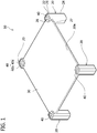
- a shelf 10 for thermal processing will be described with reference to FIG. 1 .
- the thermal processing shelf 10 is used upon arranging a process target object such as a ceramic piece into a thermal processing device such as a baking furnace. Specifically, the process target object is mounted on the thermal processing shelf 10, and the thermal processing shelf 10 is conveyed into the baking furnace. Due to this, the process target object is arranged in the baking furnace. The process target object is heated by the baking furnace in a state of being mounted on the thermal processing shelf 10. That is, the thermal processing shelf 10 is heated together with the process target object.
- the thermal processing shelf 10 includes a board 30 and four columns 20, and the board 30 is supported by the four columns 20.
- the board 30 and the columns 20 are constituted of a same material.
- the material of the board 30 and the columns 20 may, for example, be a high-strength silicon carbide (that is, SiC)-based ceramic material.
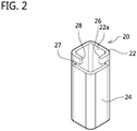
- each column 20 has a square tubular shape.
- Each column 20 includes an opposing part 22, a support part 24, and a connecting part 26.
- the opposing part 22, the support part 24, and the connecting part 26 are integrally formed.
- the material that is not yet baked is processed into the tubular shape by extrusion molding and the like, an opening 27 to be described later is formed therein by cutting out a part of the tubular shape, and by which an unfinished piece having the shape of the column 20 is manufactured. Thereafter, the unfinished piece is subjected to baking, by which the opposing part 22, the support part 24, and the connecting part 26 are integrally formed.
- the support part 24 has the square tubular shape.
- the support part 24 is to have the board 30 mounted on its upper end (see FIG.
- the connecting part 26 that extends upward on an outer side of an outer edge of the board 30 is arranged at the upper end of the support part 24 (see FIG. 1 ).
- the connecting part 26 is configured of two walls with one apex in between within the square tubular shape of the column 20. In other words, within the square tubular shape of the column 20, a portion where the connecting part 26 is not provided is opened (hereinbelow referred to as the "opening 27").
- a length of the connecting part 26 in an up-and-down direction is somewhat larger than a thiclrness of the board 30.
- the opposing part 22 is arranged at an upper end of the connecting part 26.
- the opposing part 22 within the square tubular shape of the column 20, parts of two walls that intervene one apex where the connecting part 26 is not provided (an apex on a sheet front side in FIG. 2 ) are notched. That is, the opposing part 22 has a notch 28 at a position corresponding to the one apex where the connecting part 26 is not provided.
- the notch 28 is arranged above the opening 27 of the connecting part 26.
- the board 30 has a square flat plate shape.
- Each of an upper surface 30a and a lower surface 30b (see FIG 5 ) of the board 30 has a flat shape, and is arranged along a horizontal direction.
- the board 30 is supported by the columns 20 at its four corners (see FIG 1 ).
- a pin 40a is arranged at each of the four corners of the board 30.
- the pins 40a are integrally formed with the board 30 by baking. Specifically, the pins 40a and the board 30 are formed separately, and are thereafter baked in a state where the pins 40a are mounted on the board 30. Due to this, the pins 40a and the board 30 are fixed integrally.
- Each of the pins 40a has a round columnar shape.
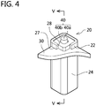
- FIG. 4 is a perspective view that enlarges a vicinity of one column 20 of the thermal processing shelf 10.
- the pin 40a is arranged inside the opposing part 22.
- a spacer 40b is arranged in a clearance between the pin 40a and the opposing part 22.
- the spacer 40b has a square annular shape. Each side of the square of the spacer 40b is longer than a width of the notch 28 of the column 20.
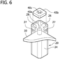
- a through hole 40c into which the pin 40a is to be inserted is arranged at a center of the spacer 40b (see FIG 6 ).
- the pin 40a and the spacer 40b will collectively be called a projection portion 40.
- Each projection portion 40 projects upward from its corresponding corner of the board 30.
- each pin 40a projects upward from the upper end of its corresponding column 20.
- Each spacer 40b is positioned lower than its corresponding pin 40a, and lower than the upper end of its corresponding columns 20.
- the columns 20, the board 30 including the pins 40a, and the spacers 40b are respectively manufactured prior to this assembling procedure.
- a plastic matter in which binders such as polyvinyl alcohol and water are added to SiC powder is subjected to press molding using molds corresponding to the shapes of the respective pieces.
- the manufacturing is completed by baking the press-molded pieces in a crucible furnace made of carbon, and impregnating the pieces with silicon.
- each corner of the board 30 is inserted into the opening 27 of the corresponding column 20 from a side where the notch 28 of the opposing part 22 of the column 20 is provided.
- a diameter of each pin 40a fixed to the board 30 is smaller than the width of the notch 28. Due to this, the pin 40a passes through the notch 28 and is arranged inside the opposing part 22.
- the spacer 40b is arranged in the clearance between the pin 40a and the opposing part 22.
- the through hole 40c of the spacer 40b is larger than the diameter of the pin 40a. Due to this, a small clearance is formed between the spacer 40b and the pin 40a. Further, the spacer 40b is somewhat smaller than an inner periphery of the opposing part 22. Due to this, a small clearance is formed between the spacer 40b and the opposing part 22. According to this configuration, the spacer 40b can be arranged easily. Further, dimensional accuracy of the respective pieces 22, 40a, 40b does not have to be controlled strictly.
- each spacer 40b is fixed to the board 30 and cannot move relative to the board 30.
- Each side of the spacer 40b is longer than the width of the notch 28 of the column 20. Due to this, in a state where the spacers 40b are fixed to the upper surface of the thermal processing shelf 10, each spacer 40b cannot pass through its corresponding notch 28. Due to this, each spacer 40b is surrounded by the opposing part 22, and thus cannot move from the inside to the outside of the opposing part 22.
- the board 30 is supported from below by the support parts 24 of the columns 20. In the up-and-down direction, the board 30 intervenes between the opposing parts 22 and the support parts 24. Due to this, the board 30 is restricted from moving in the up-and-down direction relative to the columns 20. Further, in a direction parallel to a flat surface of the flat plate shape of the board 30 (that is, the horizontal direction), the pins 40a fixed to the board 30 and the spacers 40b which are restricted from moving by the pins 40a (that is, projection portions 40) are restricted from moving by being surrounded by the opposing parts 22.
- the board 30 is restricted from moving along the flat surface of the flat plate shape of the board 30 (the motion thereof being parallel to the flat plate shape in this embodiment) relative to the columns 20. Due to this, the board 30 can be prevented from being detached from the columns 20. Especially, the board 30 can be prevented from being detached from the columns 20, even if the adhesive is no longer effective.
- thermal stress caused by heating in a heating device and cooling after having taken out of the heating device can be suppressed by manufacturing the columns 20 and the board 30 separately.
- the thermal processing shelf 10 can be utilized as a plural decker shelf by stacking plural thermal processing shelves 10 in the up-and-down direction.
- the plural decker shelf lower ends of the columns 20 of the upper thermal processing shelf 10 are stacked on upper ends of the columns 20 of the lower thermal processing shelf 10.
- the pins 40a of the columns 20 of the lower shelf are arranged in hollow parts 29 (one example of "concave portion") of the columns 20 of the upper shelf.
- the plural decker shelf is prevented from collapsing. Due to this, upon when the plural decker shelf is to be conveyed into the heating device, a worker does not need to visually confirm that the plural decker shelf does not collapse. Due to this, work efficiency can be improved.
- a shape of columns 220 differs from the shape of the columns 20 of the first embodiment.
- An opposing part 222 in each column 220 has a square annular shape that continuously surrounds its corresponding projection portion 40. That is, the opposing parts 222 do not have notches corresponding to the notches 28 of the opposing parts 22.
- Other configurations of the columns 220 are identical to those of the columns 20 of the first embodiment. That is, each the column 220 has a supporting member 224 similar to the supporting member 24.
- a procedure for assembling the columns 220 onto the board 30 is different from the first embodiment.
- the board 30 is formed integrally with the pins 40a, and the board 30 having the pins 40a fixed thereon is assembled onto the columns 20.
- the board 30 and the pins 40a are formed separately.
- the board 30 is inserted into openings 227 of the columns 220, after which the pins 40a are arranged inside the opposing parts 222 and fixed to the board 30, and the spacers 40b are arranged.
- the projection portion 40 does not need to be provided with the spacer 40b.
- a shape of columns 320 differs from the shape of the columns 20 of the first embodiment.
- Each column 320 has a round tubular shape. That is, a support part 324 of each column 320 has a round tubular shape, and an opposing part 322 has a round annular shape with a notch 328 similar to the notch 28. Further, a connecting part that connects the opposing part 322 and the support part 324 has a partially round tubular shape.
- each column 320 has an opening 327 into which the board 30 is to be inserted, similar to the opening 27, between the opposing part 322 and the support part 324.
- a spacer 340b of each projection portion 40 has a round annular shape, complying with the shape of the opposing part 322.
- a shape of columns 420 differs from the shape of the columns 20 of the first embodiment.
- Each column 420 has the same shape as the columns 220 of the second embodiment. That is, each column 420 is provided with an opposing part 422 similar to the opposing part 222, a support part 424 similar to the support part 224, and an opening 427 similar to the opening 227.
- a shape of projection portions 440 differs from that of the projection portions 40 of the first embodiment.
- Each projection portion 440 is configured of one piece.
- Each projection portion 440 has a square columnar shape complying with an inner peripheral shape of the opposing part 422.
- the projection portion 440 and the opposing part 422 are arranged with a small clearance in between.
- a shape of columns 520 differs from the shape of the columns 20 of the first embodiment.
- Each column 520 is provided with an opposing part 522 similar to the opposing part 222, a support part 524 similar to the support part 224, and an opening 527 similar to the opening 227.
- An upper end of each opposing part 522 is closed by a cover 523.
- a through hole 523a is provided at a center of each cover 523.
- the pins 40a are arranged in the through holes 523a.
- the pins 40a have a round columnar shape.
- the shape of the pins 40a is not limited to the round columnar shape, and may for example be a round tubular shape, or a polygonal tubular or columnar shape.
- each projection portion 40 is provided with one pin 40a and one spacer 40b.
- each projection portion 40 may be provided with a plurality of pins, and may be provided with a plurality of the spacers 40b.
- each projection portion 40 may be provided with a pin fixed to the board 30 inside each apex of three corners except for the notch 28 of the opposing part 22.
- three spacers may be arranged in the clearances between the opposing part 22 and respective three pins, or one spacer may be arranged in the clearance between the three pins and the opposing part 22. The same applies to other embodiments as well.
- each projection portion 40 is provided with the pin 40a and the spacer 40b.
- the projection portion 40 may be provided with the pin 40a while not being provided with the spacer 40b.
- the diameter of the pins 40a (that is, the length of the pins 40a in the flat surface direction of the board 30) may be larger than the width of the notches 28.
- the pins 40a may be fixed to the board 30 after the board 30 is inserted into the columns 20, similar to the second embodiment. The same applies to the third embodiment as well.
- the spacers 40b, 340b do not project from the upper ends of the columns 20, 220, 320. However, the spacers 40b, 340b may project from the columns 20, 220, 320 similar to the pins 40a.
- the columns 20, 220, 320, 420, 520 have a hollow tubular shape.
- the columns may have a solid columnar shape.
- portions where the board 30 is to be inserted and the projection portions are to be arranged may be hollow, and concave portions may be provided at portions where the projection portions of the columns of the lower shelf are to be inserted.
- the spacers 40b, 340b are adhered to the board 30.
- the spacers 40b, 340b may not be adhered to the board 30.
- the spacers 40b, 340b may be restricted from moving along the flat surface of the flat plate shape of the board by engaging with the pins 40a.
- the columns 20 and the board 30 can easily be disassembled by detaching the spacers 40b from the clearances between the opposing parts 22 and the pins 40a.
- the thermal processing shelf 10 can be handled space-efficiently by disassembling the board 30 and the columns 20.
- the opposing part of each column simply needs to have a shape that can restrict the projection portion 40 arranged inside the opposing part from moving from inside to outside of the opposing part when the projection portion 40 moves along the flat surface of the flat plate shape of the board 30 by the movement of the board 30.
- the opposing part may be arranged intermittently with intervals in between along a peripheral direction of its corresponding projection portion 40.
- the projection portions 40 are arranged on the upper surface of the board 30.
- the projection portions may be arranged on at least one of the upper surface and the lower surface of the board 30.
- the support parts 24 may make contact with the projection portions to restrict the board 30 from moving along the flat surface of the flat plate shape of the board 30 relative to the columns 20.
- the support parts 24 may oppose side surfaces of the respective projection portions, and surround the entire circumferences of the projection portions.
- the openings 27 may be arranged in vicinities of the lower ends of the columns 20.
- the projection portions may project downward from the lower ends of the columns 20, in which case the upper ends of the columns 20 of the lower shelf arranged under the aforementioned columns 20 may have concave portions for receiving the projection portions.
- the thermal processing shelves 10, 210, 310, 410, 510 are used to carry out heating process on the process target object.
- the thermal processing shelves 10,210, 310, 410, 510 may be used to carry out cooling process on the process target object.
- they may be used to convey the process target object into a cooling device for cooling, and convey the process target object out of the cooling device.
- the thermal processing shelves 10, 210, 310, 410, 510 may be cooled together with the process target object.
- the thermal processing shelves 10, 210, 310, 410, 510 may be used to arrange the process target object that has been heated or cooled than a normal temperature under a normal temperature environment (for example, in open air) for cooling or heating.
- the thermal processing shelves 10, 210, 310, 410, 510 may not necessarily be arranged inside the thermal processing device.
- a shelf (10) for thermal processing inludes a board (30) having a flat plate shape, a column (20) having a support part (24) which supports the board (30) from below, and an opposing part (22) which is located above the support part (24) and opposing an upper surface (30a) of the board (30), and a projection portion (40) projecting from one of the upper surface (30a) and a lower surface (30b) of the board (30) disposed between the support part (24) and the opposing part (22), wherein the projection portion (40) is restricted to move along the flat plate shape of the board (30).
Landscapes
- Engineering & Computer Science (AREA)
- Mechanical Engineering (AREA)
- General Engineering & Computer Science (AREA)
- Container, Conveyance, Adherence, Positioning, Of Wafer (AREA)
- Furnace Charging Or Discharging (AREA)
Abstract
Description
- The technique disclosed herein relates to a shelf for thermal processing used in a thermal processing device. Notably, the thermal processing includes heating process and cooling process.
- A shelf for thermal processing is used to convey a process target object of thermal processing into a thermal processing device such as a furnace, and to heat or cool the process target object. This shelf has a board mounted on a column. A technique for attaching the column to the board is being considered for this shelf so that the board will not be detached from the column while conveying the process target object.
- A shelf for thermal processing described in Japanese Patent Application Publication No.
H10-141867 - The board of the shelf for thermal processing as above has a reduced strength in vicinities of the through holes due to the through holes for inserting the columns being provided in the board. Due to this, for example, a total weight of the process target object to be mounted on the board need to be set by taking the strength in the vicinities of the through holes into account. In this disclosure, a technique to attach a board to a column without providing a through hole in the board will be provided.
- The technique disclosed herein is a shelf for thermal processing that is to be used in thermal processing. The shelf for thermal processing includes a board, a column, and a projection portion. The board has a flat plate shape. The column has a support part which supports the board from below, and an opposing part which is located above the support part and opposing an upper surface of the board. The projection portion projects from one of the upper surface and a lower surface of the board disposed between the support part and the opposing part. The projection portion is restricted to move along the flat plate shape of the board. One of the support part and the opposing part that is located on a side of the one of the upper surface and the lower surface opposes a side surface of the projection portion, and makes contact with the projection portion to restrict the board from moving relative to the column along the flat plate shape.
- According to this configuration, the board can be restricted from being displaced relative to the column in an up-and-down direction by providing the board between the support part and the opposing part of the column. Further, the board is restricted from being displaced relative to the column along the flat plate shape of the board, by the contact between the projection portion projecting from the board and the one of the support part and the opposing part opposing the projection portion. According to this configuration, the board can be firmly attached to the column without providing a through hole in the board.
-
FIG. 1 is a perspective view of a shelf for thermal processing of an embodiment; -
FIG 2 is a perspective view of a column of the embodiment; -
FIG 3 is a perspective view of a board of the embodiment; -
FIG 4 is an enlarged perspective view in a vicinity of the column of the shelf for thermal processing of the embodiment; -
FIG 5 is a cross sectional view along a line V-V inFIG 4 ; -
FIG 6 is a perspective view for explaining an assembling method of the shelf for thermal processing of the embodiment; -
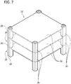
FIG 7 is a perspective view for a case of combining plural stacks of the shelves for thermal processing of the embodiment; -
FIG 8 is an enlarged perspective view in a vicinity of a column of a shelf for thermal processing of a second embodiment; -
FIG 9 is an enlarged perspective view in a vicinity of a column of a shelf for thermal processing of a third embodiment; -
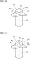
FIG 10 is an enlarged perspective view in a vicinity of a column of a shelf for thermal processing of a fourth embodiment; and -
FIG. 11 is an enlarged perspective view in a vicinity of a column of a shelf for thermal processing of a fifth embodiment. - Primary features of embodiments described hereinbelow will be listed. Each technical element described hereinbelow is a technical element independent of one another, and may have technical utility on its own or in various combinations.
- In a shelf for thermal processing of the embodiments, a projection portion may project from one of an upper end and a lower end of a column. The column may include a concave portion at the other of the upper end and the lower end of the column. The concave portion may be larger than the projection portion. With this shelf for thermal processing, a plural decker shelf can be configured by stacking plural columns of the shelve for thermal processing. In doing so, the projection portion of the column of the shelf for thermal processing can be inserted into the concave portion provided at the one of the upper end and the lower end of the column of the shelf for thermal processing, by which the columns stacked on top of one another can be suppressed from being displaced relative to one another.
- In the shelf for thermal processing of the embodiments, the projection portion may include a pin fixed to a board, wherein the pin and one of a support part and an opposing part may be disposed with a clearance therebetween, and a spacer engaged with the pin and disposed in the clearance between the pin and the one of the support part and the opposing part.
- In the shelf for thermal processing of the embodiments, the one of the support part and the opposing part may include a notch, and the notch may allow the pin to pass therethrough and may not allow the spacer to pass therethrough when the board is moved relative to the column along a flat plate shape of the board. According to this configuration, the board can be assembled onto the column by firstly fixing the pin to the board and thereafter arranging the pin from an outside into an inside of the one of the support part and the opposing part through the notch. Further, the board can be prevented from being detached from the column by arranging the spacer between the pin and the one of the support part and the opposing part after having assembled the board onto the column.
- In the shelf for thermal processing of the embodiments, the opposing part and the board may be disposed with a clearance therebetween. Upon assembling the board onto the column, when the board is inserted into a clearance between the support part and the opposing part, the board can be suppressed from making contact with the column. Due to this, a situation in which the board and the column make contact while assembling the board onto the column and resulting in breakage can be avoided.
- In the shelf for thermal processing of the embodiments, the projection portion and the one of the support part and the opposing part may be disposed with a clearance therebetween.
- A
shelf 10 for thermal processing will be described with reference toFIG. 1 . Thethermal processing shelf 10 is used upon arranging a process target object such as a ceramic piece into a thermal processing device such as a baking furnace. Specifically, the process target object is mounted on thethermal processing shelf 10, and thethermal processing shelf 10 is conveyed into the baking furnace. Due to this, the process target object is arranged in the baking furnace. The process target object is heated by the baking furnace in a state of being mounted on thethermal processing shelf 10. That is, thethermal processing shelf 10 is heated together with the process target object. - The
thermal processing shelf 10 includes aboard 30 and fourcolumns 20, and theboard 30 is supported by the fourcolumns 20. Theboard 30 and thecolumns 20 are constituted of a same material. The material of theboard 30 and thecolumns 20 may, for example, be a high-strength silicon carbide (that is, SiC)-based ceramic material. - As shown in
FIG. 2 , eachcolumn 20 has a square tubular shape. Eachcolumn 20 includes anopposing part 22, asupport part 24, and a connectingpart 26. Theopposing part 22, thesupport part 24, and the connectingpart 26 are integrally formed. Specifically, the material that is not yet baked is processed into the tubular shape by extrusion molding and the like, anopening 27 to be described later is formed therein by cutting out a part of the tubular shape, and by which an unfinished piece having the shape of thecolumn 20 is manufactured. Thereafter, the unfinished piece is subjected to baking, by which the opposingpart 22, thesupport part 24, and the connectingpart 26 are integrally formed. Thesupport part 24 has the square tubular shape. Thesupport part 24 is to have theboard 30 mounted on its upper end (seeFIG. 1 ), and supports theboard 30 from below. The connectingpart 26 that extends upward on an outer side of an outer edge of theboard 30 is arranged at the upper end of the support part 24 (seeFIG. 1 ). The connectingpart 26 is configured of two walls with one apex in between within the square tubular shape of thecolumn 20. In other words, within the square tubular shape of thecolumn 20, a portion where the connectingpart 26 is not provided is opened (hereinbelow referred to as the "opening 27"). A length of the connectingpart 26 in an up-and-down direction is somewhat larger than a thiclrness of theboard 30. - The opposing
part 22 is arranged at an upper end of the connectingpart 26. In the opposingpart 22, within the square tubular shape of thecolumn 20, parts of two walls that intervene one apex where the connectingpart 26 is not provided (an apex on a sheet front side inFIG. 2 ) are notched. That is, the opposingpart 22 has anotch 28 at a position corresponding to the one apex where the connectingpart 26 is not provided. Thenotch 28 is arranged above theopening 27 of the connectingpart 26. - As shown in
FIG 3 , theboard 30 has a square flat plate shape. Each of anupper surface 30a and alower surface 30b (seeFIG 5 ) of theboard 30 has a flat shape, and is arranged along a horizontal direction. Theboard 30 is supported by thecolumns 20 at its four corners (seeFIG 1 ). Apin 40a is arranged at each of the four corners of theboard 30. Thepins 40a are integrally formed with theboard 30 by baking. Specifically, thepins 40a and theboard 30 are formed separately, and are thereafter baked in a state where thepins 40a are mounted on theboard 30. Due to this, thepins 40a and theboard 30 are fixed integrally. Each of thepins 40a has a round columnar shape. -
FIG. 4 is a perspective view that enlarges a vicinity of onecolumn 20 of thethermal processing shelf 10. Thepin 40a is arranged inside the opposingpart 22. Aspacer 40b is arranged in a clearance between thepin 40a and the opposingpart 22. Thespacer 40b has a square annular shape. Each side of the square of thespacer 40b is longer than a width of thenotch 28 of thecolumn 20. A throughhole 40c into which thepin 40a is to be inserted is arranged at a center of thespacer 40b (seeFIG 6 ). Notably, thepin 40a and thespacer 40b will collectively be called aprojection portion 40. Eachprojection portion 40 projects upward from its corresponding corner of theboard 30. - As shown in
FIG 5 , eachpin 40a projects upward from the upper end of itscorresponding column 20. Eachspacer 40b is positioned lower than itscorresponding pin 40a, and lower than the upper end of itscorresponding columns 20. - Next, a procedure for assembling the
columns 20 onto theboard 30 will be described. Notably, thecolumns 20, theboard 30 including thepins 40a, and thespacers 40b are respectively manufactured prior to this assembling procedure. Specifically, a plastic matter in which binders such as polyvinyl alcohol and water are added to SiC powder is subjected to press molding using molds corresponding to the shapes of the respective pieces. Then, the manufacturing is completed by baking the press-molded pieces in a crucible furnace made of carbon, and impregnating the pieces with silicon. - The
columns 20 shown inFIG 2 are assembled onto the respective four corners ofboard 30 shown inFIG. 3 . As shown inFIG 6 , each corner of theboard 30 is inserted into theopening 27 of thecorresponding column 20 from a side where thenotch 28 of the opposingpart 22 of thecolumn 20 is provided. A diameter of eachpin 40a fixed to theboard 30 is smaller than the width of thenotch 28. Due to this, thepin 40a passes through thenotch 28 and is arranged inside the opposingpart 22. - Then, the
spacer 40b is arranged in the clearance between thepin 40a and the opposingpart 22. The throughhole 40c of thespacer 40b is larger than the diameter of thepin 40a. Due to this, a small clearance is formed between the spacer 40b and thepin 40a. Further, thespacer 40b is somewhat smaller than an inner periphery of the opposingpart 22. Due to this, a small clearance is formed between the spacer 40b and the opposingpart 22. According to this configuration, thespacer 40b can be arranged easily. Further, dimensional accuracy of therespective pieces - Then, the
board 30 and thesupport parts 24 of thecolumns 20 are adhered. Further, theboard 30 and thespacers 40b are adhered. Notably, as an adhesive, for example, a SiC-based adhesive may be used. Due to this, thespacers 40b are fixed to theboard 30 and cannot move relative to theboard 30. Each side of thespacer 40b is longer than the width of thenotch 28 of thecolumn 20. Due to this, in a state where thespacers 40b are fixed to the upper surface of thethermal processing shelf 10, eachspacer 40b cannot pass through itscorresponding notch 28. Due to this, eachspacer 40b is surrounded by the opposingpart 22, and thus cannot move from the inside to the outside of the opposingpart 22. - The
board 30 is supported from below by thesupport parts 24 of thecolumns 20. In the up-and-down direction, theboard 30 intervenes between the opposingparts 22 and thesupport parts 24. Due to this, theboard 30 is restricted from moving in the up-and-down direction relative to thecolumns 20. Further, in a direction parallel to a flat surface of the flat plate shape of the board 30 (that is, the horizontal direction), thepins 40a fixed to theboard 30 and thespacers 40b which are restricted from moving by thepins 40a (that is, projection portions 40) are restricted from moving by being surrounded by the opposingparts 22. As a result, theboard 30 is restricted from moving along the flat surface of the flat plate shape of the board 30 (the motion thereof being parallel to the flat plate shape in this embodiment) relative to thecolumns 20. Due to this, theboard 30 can be prevented from being detached from thecolumns 20. Especially, theboard 30 can be prevented from being detached from thecolumns 20, even if the adhesive is no longer effective. On the other hand, as compared to a configuration in which thecolumns 20 and theboard 30 are manufactured integrally, thermal stress caused by heating in a heating device and cooling after having taken out of the heating device can be suppressed by manufacturing thecolumns 20 and theboard 30 separately. - Further, as shown in
FIG. 7 , thethermal processing shelf 10 can be utilized as a plural decker shelf by stacking pluralthermal processing shelves 10 in the up-and-down direction. In the plural decker shelf, lower ends of thecolumns 20 of the upperthermal processing shelf 10 are stacked on upper ends of thecolumns 20 of the lowerthermal processing shelf 10. In this configuration, as shown inFIG 5 , thepins 40a of thecolumns 20 of the lower shelf are arranged in hollow parts 29 (one example of "concave portion") of thecolumns 20 of the upper shelf. As a result, if thecolumns 20 of the upper shelf are to be displaced in a direction parallel to theboard 30 relative to thecolumns 20 of the lower shelf, thepins 40a of thecolumns 20 of the lower shelf are caught by outer walls of thecolumns 20 of the upper shelf, and thecolumns 20 of the upper shelf can be prevented from falling off of thecolumns 20 of the lower shelf. As a result, the plural decker shelf is prevented from collapsing. Due to this, upon when the plural decker shelf is to be conveyed into the heating device, a worker does not need to visually confirm that the plural decker shelf does not collapse. Due to this, work efficiency can be improved. - Features different from the first embodiment will be described with reference to
FIG. 8 . In athermal processing shelf 210 of the second embodiment, a shape ofcolumns 220 differs from the shape of thecolumns 20 of the first embodiment. Anopposing part 222 in eachcolumn 220 has a square annular shape that continuously surrounds itscorresponding projection portion 40. That is, the opposingparts 222 do not have notches corresponding to thenotches 28 of the opposingparts 22. Other configurations of thecolumns 220 are identical to those of thecolumns 20 of the first embodiment. That is, each thecolumn 220 has a supportingmember 224 similar to the supportingmember 24. - Further, in the second embodiment, a procedure for assembling the
columns 220 onto theboard 30 is different from the first embodiment. In the first embodiment, theboard 30 is formed integrally with thepins 40a, and theboard 30 having thepins 40a fixed thereon is assembled onto thecolumns 20. On the other hand, in the second embodiment, theboard 30 and thepins 40a are formed separately. Then, theboard 30 is inserted intoopenings 227 of thecolumns 220, after which thepins 40a are arranged inside the opposingparts 222 and fixed to theboard 30, and thespacers 40b are arranged. Notably, as in the second embodiment, in the configuration in which eachopposing part 222 surrounds itscorresponding pin 40a, theprojection portion 40 does not need to be provided with thespacer 40b. Despite the lack of thespacers 40b, when theboard 30 is displaced parallel to the flat surface of theboard 30 relative to thecolumns 220, a situation in which thecolumns 220 are detached from theboard 30 can be avoided by thepins 40a making contact with the opposingparts 222. - Features different from the first embodiment will be described with reference to
FIG. 9 . In athermal processing shelf 310 of the third embodiment, a shape ofcolumns 320 differs from the shape of thecolumns 20 of the first embodiment. Eachcolumn 320 has a round tubular shape. That is, asupport part 324 of eachcolumn 320 has a round tubular shape, and anopposing part 322 has a round annular shape with anotch 328 similar to thenotch 28. Further, a connecting part that connects the opposingpart 322 and thesupport part 324 has a partially round tubular shape. Moreover, eachcolumn 320 has anopening 327 into which theboard 30 is to be inserted, similar to theopening 27, between theopposing part 322 and thesupport part 324. - A
spacer 340b of eachprojection portion 40 has a round annular shape, complying with the shape of the opposingpart 322. - Features different from the first embodiment will be described with reference to
FIG. 10 . In athermal processing shelf 410 of the fourth embodiment, a shape ofcolumns 420 differs from the shape of thecolumns 20 of the first embodiment. Eachcolumn 420 has the same shape as thecolumns 220 of the second embodiment. That is, eachcolumn 420 is provided with an opposingpart 422 similar to the opposingpart 222, asupport part 424 similar to thesupport part 224, and anopening 427 similar to theopening 227. - Further, a shape of
projection portions 440 differs from that of theprojection portions 40 of the first embodiment. Eachprojection portion 440 is configured of one piece. Eachprojection portion 440 has a square columnar shape complying with an inner peripheral shape of the opposingpart 422. Theprojection portion 440 and the opposingpart 422 are arranged with a small clearance in between. - Features different from the first embodiment will be described with reference to
FIG. 11 . In athermal processing shelf 510 of the fifth embodiment, a shape ofcolumns 520 differs from the shape of thecolumns 20 of the first embodiment. Eachcolumn 520 is provided with an opposingpart 522 similar to the opposingpart 222, asupport part 524 similar to thesupport part 224, and anopening 527 similar to theopening 227. An upper end of eachopposing part 522 is closed by acover 523. A throughhole 523a is provided at a center of eachcover 523. Thepins 40a are arranged in the throughholes 523a. - Specific examples of the invention disclosed herein have been described in detail, however, these are mere examples, and do not limit the scope of the claims. The techniques described in the claims include variations and alterations of the above-exemplified specific examples.
- In the above embodiments, the
pins 40a have a round columnar shape. However, the shape of thepins 40a is not limited to the round columnar shape, and may for example be a round tubular shape, or a polygonal tubular or columnar shape. - In the first embodiment, each
projection portion 40 is provided with onepin 40a and onespacer 40b. However, eachprojection portion 40 may be provided with a plurality of pins, and may be provided with a plurality of thespacers 40b. For example, in the first embodiment, eachprojection portion 40 may be provided with a pin fixed to theboard 30 inside each apex of three corners except for thenotch 28 of the opposingpart 22. In this configuration, three spacers may be arranged in the clearances between the opposingpart 22 and respective three pins, or one spacer may be arranged in the clearance between the three pins and the opposingpart 22. The same applies to other embodiments as well. - In the first embodiment, each
projection portion 40 is provided with thepin 40a and thespacer 40b. However, theprojection portion 40 may be provided with thepin 40a while not being provided with thespacer 40b. In this case, the diameter of thepins 40a (that is, the length of thepins 40a in the flat surface direction of the board 30) may be larger than the width of thenotches 28. Further, thepins 40a may be fixed to theboard 30 after theboard 30 is inserted into thecolumns 20, similar to the second embodiment. The same applies to the third embodiment as well. - In the first to third embodiments, the
spacers columns spacers columns pins 40a. - In the respective embodiments, the
columns board 30 is to be inserted and the projection portions are to be arranged may be hollow, and concave portions may be provided at portions where the projection portions of the columns of the lower shelf are to be inserted. - In the first to third embodiments, the
spacers board 30. However, thespacers board 30. In this configuration, thespacers pins 40a. According to this configuration, for example in the first embodiment, thecolumns 20 and theboard 30 can easily be disassembled by detaching thespacers 40b from the clearances between the opposingparts 22 and thepins 40a. As a result, for example, when one of thecolumns 20 and theboard 30 is damaged, the damaged one can easily be replaced. Further, upon transporting and storing thethermal processing shelf 10, thethermal processing shelf 10 can be handled space-efficiently by disassembling theboard 30 and thecolumns 20. - The opposing part of each column simply needs to have a shape that can restrict the
projection portion 40 arranged inside the opposing part from moving from inside to outside of the opposing part when theprojection portion 40 moves along the flat surface of the flat plate shape of theboard 30 by the movement of theboard 30. For example, the opposing part may be arranged intermittently with intervals in between along a peripheral direction of itscorresponding projection portion 40. - In the first embodiment, the
projection portions 40 are arranged on the upper surface of theboard 30. However, the projection portions may be arranged on at least one of the upper surface and the lower surface of theboard 30. In a case where the projection portions are arranged on the lower surface of theboard 30, thesupport parts 24 may make contact with the projection portions to restrict theboard 30 from moving along the flat surface of the flat plate shape of theboard 30 relative to thecolumns 20. For example, thesupport parts 24 may oppose side surfaces of the respective projection portions, and surround the entire circumferences of the projection portions. In this case, theopenings 27 may be arranged in vicinities of the lower ends of thecolumns 20. Further, the projection portions may project downward from the lower ends of thecolumns 20, in which case the upper ends of thecolumns 20 of the lower shelf arranged under theaforementioned columns 20 may have concave portions for receiving the projection portions. - In the above embodiments, the
thermal processing shelves thermal processing shelves thermal processing shelves thermal processing shelves - Further, the technical elements disclosed in the description and the drawings exhibit technical usefulness independently or in various combinations, and are not limited to the combinations described in the claims as originally filed. Further, the techniques exemplified in the description and the drawings concurrently achieve plural aims, and have the technical usefulness simply by achieving one of such aims.
- A shelf (10) for thermal processing inludes a board (30) having a flat plate shape, a column (20) having a support part (24) which supports the board (30) from below, and an opposing part (22) which is located above the support part (24) and opposing an upper surface (30a) of the board (30), and a projection portion (40) projecting from one of the upper surface (30a) and a lower surface (30b) of the board (30) disposed between the support part (24) and the opposing part (22), wherein the projection portion (40) is restricted to move along the flat plate shape of the board (30). One of the support part (24) and the opposing part (22) that is located on a side of the one of the upper surface (30a) and the lower surface (30b) opposes a side surface of the projection portion (40), and makes contact with the projection portion (40) to restrict the board (30) from moving relative to the column (20) along the flat plate shape of the board (30).
Claims (6)
- A shelf (10) for thermal processing comprising:a board (30) having a flat plate shape;a column (20) comprising a support part (24) which supports the board (30) from below, and an opposing part (22) which is located above the support part (24) and opposing an upper surface (30a) of the board (30); anda projection portion (40) projecting from one of the upper surface (30a) and a lower surface (30b) of the board (30) disposed between the support part (24) and the opposing part (22), wherein the projection portion (40) is restricted to move along the flat plate shape of the board (30),wherein one of the support part (24) and the opposing part (22) that is located on a side of the one of the upper surface (30a) and the lower surface (30b) opposes a side surface of the projection portion (40), and makes contact with the projection portion (40) to restrict the board (30) from moving relative to the column (20) along the flat plate shape of the board (30).
- The shelf (10) as in claim 1, wherein
the projection portion (40) projects from one of an upper end and a lower end of the column (20),
the column (20) comprises a concave portion (29) at the other of the upper end and the lower end of the column (20), and
the concave portion (29) is larger than the projection portion (40). - The shelf (10) as in claim 1 or 2, wherein
the projection portion (40) comprises:a pin (40a) fixed to the board (30), wherein the pin (40a) and the one of the support part (24) and the opposing part (22) are disposed with a clearance therebetween; anda spacer (40b) engaged with the pin (40a) and disposed in the clearance between the pin (40a) and the one of the support part (24) and the opposing part (22). - The shelf (10) as in claim 3, wherein
the one of the support part (24) and the opposing part (22) comprises a notch (28), and
the notch (28) allows the pin (40a) to pass therethrough and does not allow the spacer (40b) to pass therethrough when the board (30) is moved relative to the column along the flat plate shape of the board (30). - The shelf (10) as in any one of claims 1 to 4, wherein
the opposing part (22) and the board (30) are disposed with a clearance therebetween. - The shelf (10) as in any one of claims 1 to 5, wherein
the projection portion (40) and the one of the support part (24) and the opposing part (22) are disposed with a clearance therebetween.
Priority Applications (1)
| Application Number | Priority Date | Filing Date | Title |
|---|---|---|---|
| PL16193671T PL3156750T3 (en) | 2015-10-14 | 2016-10-13 | Shelf for thermal processing |
Applications Claiming Priority (1)
| Application Number | Priority Date | Filing Date | Title |
|---|---|---|---|
| JP2015202833A JP6378155B2 (en) | 2015-10-14 | 2015-10-14 | Heat treatment shelf |
Publications (2)
| Publication Number | Publication Date |
|---|---|
| EP3156750A1 true EP3156750A1 (en) | 2017-04-19 |
| EP3156750B1 EP3156750B1 (en) | 2020-01-15 |
Family
ID=57280951
Family Applications (1)
| Application Number | Title | Priority Date | Filing Date |
|---|---|---|---|
| EP16193671.1A Active EP3156750B1 (en) | 2015-10-14 | 2016-10-13 | Shelf for thermal processing |
Country Status (3)
| Country | Link |
|---|---|
| EP (1) | EP3156750B1 (en) |
| JP (1) | JP6378155B2 (en) |
| PL (1) | PL3156750T3 (en) |
Cited By (3)
| Publication number | Priority date | Publication date | Assignee | Title |
|---|---|---|---|---|
| US11280549B2 (en) * | 2018-06-20 | 2022-03-22 | Saint-Gobain Industriekeramik Rödental GmbH | Multi-part support element for spacing carrier elements |
| WO2024160747A1 (en) * | 2023-01-30 | 2024-08-08 | Saint-Gobain Industriekeramik Rödental GmbH | Multipart ceramic support element |
| US12146736B2 (en) | 2018-02-28 | 2024-11-19 | Industrial Metrology Solutions Llc | Metrology system |
Citations (7)
| Publication number | Priority date | Publication date | Assignee | Title |
|---|---|---|---|---|
| US2923997A (en) * | 1960-02-09 | emmerling | ||
| GB1421504A (en) * | 1973-08-18 | 1976-01-21 | Acme Marls Ltd | Support for pottery articles |
| FR2357845A1 (en) * | 1976-07-09 | 1978-02-03 | Decize Boigues Cie Usine Ceram | Stackable tray supporting enamelled tiles during baking - where one set of trays can carry tiles of different thickness |
| GB2183805A (en) * | 1985-11-28 | 1987-06-10 | Hewitt & Son J | Kiln furniture |
| JPH10111084A (en) * | 1996-10-04 | 1998-04-28 | Ngk Insulators Ltd | Baking shelf board and baking method using it |
| JPH10141867A (en) | 1996-11-13 | 1998-05-29 | Murata Mfg Co Ltd | Heat treating jig |
| JP2000009389A (en) * | 1998-06-19 | 2000-01-14 | Nichias Corp | Ceramic firing shelf |
Family Cites Families (1)
| Publication number | Priority date | Publication date | Assignee | Title |
|---|---|---|---|---|
| JP3523968B2 (en) * | 1996-10-31 | 2004-04-26 | 三井金属鉱業株式会社 | Furnace shelves |
-
2015
- 2015-10-14 JP JP2015202833A patent/JP6378155B2/en not_active Expired - Fee Related
-
2016
- 2016-10-13 EP EP16193671.1A patent/EP3156750B1/en active Active
- 2016-10-13 PL PL16193671T patent/PL3156750T3/en unknown
Patent Citations (7)
| Publication number | Priority date | Publication date | Assignee | Title |
|---|---|---|---|---|
| US2923997A (en) * | 1960-02-09 | emmerling | ||
| GB1421504A (en) * | 1973-08-18 | 1976-01-21 | Acme Marls Ltd | Support for pottery articles |
| FR2357845A1 (en) * | 1976-07-09 | 1978-02-03 | Decize Boigues Cie Usine Ceram | Stackable tray supporting enamelled tiles during baking - where one set of trays can carry tiles of different thickness |
| GB2183805A (en) * | 1985-11-28 | 1987-06-10 | Hewitt & Son J | Kiln furniture |
| JPH10111084A (en) * | 1996-10-04 | 1998-04-28 | Ngk Insulators Ltd | Baking shelf board and baking method using it |
| JPH10141867A (en) | 1996-11-13 | 1998-05-29 | Murata Mfg Co Ltd | Heat treating jig |
| JP2000009389A (en) * | 1998-06-19 | 2000-01-14 | Nichias Corp | Ceramic firing shelf |
Cited By (3)
| Publication number | Priority date | Publication date | Assignee | Title |
|---|---|---|---|---|
| US12146736B2 (en) | 2018-02-28 | 2024-11-19 | Industrial Metrology Solutions Llc | Metrology system |
| US11280549B2 (en) * | 2018-06-20 | 2022-03-22 | Saint-Gobain Industriekeramik Rödental GmbH | Multi-part support element for spacing carrier elements |
| WO2024160747A1 (en) * | 2023-01-30 | 2024-08-08 | Saint-Gobain Industriekeramik Rödental GmbH | Multipart ceramic support element |
Also Published As
| Publication number | Publication date |
|---|---|
| JP6378155B2 (en) | 2018-08-22 |
| JP2017075726A (en) | 2017-04-20 |
| PL3156750T3 (en) | 2021-07-19 |
| EP3156750B1 (en) | 2020-01-15 |
Similar Documents
| Publication | Publication Date | Title |
|---|---|---|
| EP3156750B1 (en) | Shelf for thermal processing | |
| JP6274454B2 (en) | Firing jig | |
| KR20130130676A (en) | Rack for firing | |
| KR200486265Y1 (en) | Container for storing substrates | |
| US12478972B2 (en) | Spacer plate, a stackable rack, a stacked assembly of at least two racks, and use of a spacer plate | |
| JP6337962B2 (en) | Heat treatment jig | |
| JP4718864B2 (en) | Press mold and press molding method | |
| KR101610293B1 (en) | Cassette for loading glass | |
| US20170120550A1 (en) | Hot plate structure of press molding device and continuous molding method using same | |
| JPH11304371A (en) | Baking rack | |
| JP6735334B2 (en) | Firing torch and method for manufacturing honeycomb structure using firing torch | |
| JP7158925B2 (en) | Forming mold disassembly and assembly equipment | |
| KR101651820B1 (en) | Fine blanking press apparatus | |
| JP5595020B2 (en) | Hacker for slit coil | |
| KR101178730B1 (en) | Shelf for showcase | |
| KR101753683B1 (en) | Prefabricated setter | |
| JPH10227579A (en) | Supporting pillar for setter of kiln | |
| KR200455345Y1 (en) | Conveyor frame | |
| JP6566256B2 (en) | Method of assembling a die device for hot forging | |
| JP5529590B2 (en) | Firing jig | |
| JP2016003823A (en) | Workpiece support tool within heat-treating furnace | |
| KR101610239B1 (en) | Space adjusting device for drying rack | |
| JP2017078007A (en) | Glass article holding jig, and production method of glass article | |
| JP2010078169A (en) | Baking tool for ceramic mold | |
| JP2008050861A (en) | Tile |
Legal Events
| Date | Code | Title | Description |
|---|---|---|---|
| PUAI | Public reference made under article 153(3) epc to a published international application that has entered the european phase |
Free format text: ORIGINAL CODE: 0009012 |
|
| STAA | Information on the status of an ep patent application or granted ep patent |
Free format text: STATUS: THE APPLICATION HAS BEEN PUBLISHED |
|
| AK | Designated contracting states |
Kind code of ref document: A1 Designated state(s): AL AT BE BG CH CY CZ DE DK EE ES FI FR GB GR HR HU IE IS IT LI LT LU LV MC MK MT NL NO PL PT RO RS SE SI SK SM TR |
|
| AX | Request for extension of the european patent |
Extension state: BA ME |
|
| STAA | Information on the status of an ep patent application or granted ep patent |
Free format text: STATUS: REQUEST FOR EXAMINATION WAS MADE |
|
| 17P | Request for examination filed |
Effective date: 20170821 |
|
| RBV | Designated contracting states (corrected) |
Designated state(s): AL AT BE BG CH CY CZ DE DK EE ES FI FR GB GR HR HU IE IS IT LI LT LU LV MC MK MT NL NO PL PT RO RS SE SI SK SM TR |
|
| STAA | Information on the status of an ep patent application or granted ep patent |
Free format text: STATUS: EXAMINATION IS IN PROGRESS |
|
| 17Q | First examination report despatched |
Effective date: 20180305 |
|
| GRAP | Despatch of communication of intention to grant a patent |
Free format text: ORIGINAL CODE: EPIDOSNIGR1 |
|
| STAA | Information on the status of an ep patent application or granted ep patent |
Free format text: STATUS: GRANT OF PATENT IS INTENDED |
|
| INTG | Intention to grant announced |
Effective date: 20190729 |
|
| GRAS | Grant fee paid |
Free format text: ORIGINAL CODE: EPIDOSNIGR3 |
|
| GRAA | (expected) grant |
Free format text: ORIGINAL CODE: 0009210 |
|
| STAA | Information on the status of an ep patent application or granted ep patent |
Free format text: STATUS: THE PATENT HAS BEEN GRANTED |
|
| AK | Designated contracting states |
Kind code of ref document: B1 Designated state(s): AL AT BE BG CH CY CZ DE DK EE ES FI FR GB GR HR HU IE IS IT LI LT LU LV MC MK MT NL NO PL PT RO RS SE SI SK SM TR |
|
| REG | Reference to a national code |
Ref country code: CH Ref legal event code: EP Ref country code: GB Ref legal event code: FG4D |
|
| REG | Reference to a national code |
Ref country code: IE Ref legal event code: FG4D |
|
| REG | Reference to a national code |
Ref country code: DE Ref legal event code: R096 Ref document number: 602016028201 Country of ref document: DE |
|
| REG | Reference to a national code |
Ref country code: AT Ref legal event code: REF Ref document number: 1225515 Country of ref document: AT Kind code of ref document: T Effective date: 20200215 |
|
| REG | Reference to a national code |
Ref country code: NL Ref legal event code: MP Effective date: 20200115 |
|
| REG | Reference to a national code |
Ref country code: LT Ref legal event code: MG4D |
|
| PG25 | Lapsed in a contracting state [announced via postgrant information from national office to epo] |
Ref country code: NO Free format text: LAPSE BECAUSE OF FAILURE TO SUBMIT A TRANSLATION OF THE DESCRIPTION OR TO PAY THE FEE WITHIN THE PRESCRIBED TIME-LIMIT Effective date: 20200415 Ref country code: PT Free format text: LAPSE BECAUSE OF FAILURE TO SUBMIT A TRANSLATION OF THE DESCRIPTION OR TO PAY THE FEE WITHIN THE PRESCRIBED TIME-LIMIT Effective date: 20200607 Ref country code: FI Free format text: LAPSE BECAUSE OF FAILURE TO SUBMIT A TRANSLATION OF THE DESCRIPTION OR TO PAY THE FEE WITHIN THE PRESCRIBED TIME-LIMIT Effective date: 20200115 Ref country code: NL Free format text: LAPSE BECAUSE OF FAILURE TO SUBMIT A TRANSLATION OF THE DESCRIPTION OR TO PAY THE FEE WITHIN THE PRESCRIBED TIME-LIMIT Effective date: 20200115 Ref country code: RS Free format text: LAPSE BECAUSE OF FAILURE TO SUBMIT A TRANSLATION OF THE DESCRIPTION OR TO PAY THE FEE WITHIN THE PRESCRIBED TIME-LIMIT Effective date: 20200115 |
|
| PG25 | Lapsed in a contracting state [announced via postgrant information from national office to epo] |
Ref country code: IS Free format text: LAPSE BECAUSE OF FAILURE TO SUBMIT A TRANSLATION OF THE DESCRIPTION OR TO PAY THE FEE WITHIN THE PRESCRIBED TIME-LIMIT Effective date: 20200515 Ref country code: SE Free format text: LAPSE BECAUSE OF FAILURE TO SUBMIT A TRANSLATION OF THE DESCRIPTION OR TO PAY THE FEE WITHIN THE PRESCRIBED TIME-LIMIT Effective date: 20200115 Ref country code: LV Free format text: LAPSE BECAUSE OF FAILURE TO SUBMIT A TRANSLATION OF THE DESCRIPTION OR TO PAY THE FEE WITHIN THE PRESCRIBED TIME-LIMIT Effective date: 20200115 Ref country code: GR Free format text: LAPSE BECAUSE OF FAILURE TO SUBMIT A TRANSLATION OF THE DESCRIPTION OR TO PAY THE FEE WITHIN THE PRESCRIBED TIME-LIMIT Effective date: 20200416 Ref country code: HR Free format text: LAPSE BECAUSE OF FAILURE TO SUBMIT A TRANSLATION OF THE DESCRIPTION OR TO PAY THE FEE WITHIN THE PRESCRIBED TIME-LIMIT Effective date: 20200115 Ref country code: BG Free format text: LAPSE BECAUSE OF FAILURE TO SUBMIT A TRANSLATION OF THE DESCRIPTION OR TO PAY THE FEE WITHIN THE PRESCRIBED TIME-LIMIT Effective date: 20200415 |
|
| REG | Reference to a national code |
Ref country code: DE Ref legal event code: R097 Ref document number: 602016028201 Country of ref document: DE |
|
| PG25 | Lapsed in a contracting state [announced via postgrant information from national office to epo] |
Ref country code: DK Free format text: LAPSE BECAUSE OF FAILURE TO SUBMIT A TRANSLATION OF THE DESCRIPTION OR TO PAY THE FEE WITHIN THE PRESCRIBED TIME-LIMIT Effective date: 20200115 Ref country code: SM Free format text: LAPSE BECAUSE OF FAILURE TO SUBMIT A TRANSLATION OF THE DESCRIPTION OR TO PAY THE FEE WITHIN THE PRESCRIBED TIME-LIMIT Effective date: 20200115 Ref country code: EE Free format text: LAPSE BECAUSE OF FAILURE TO SUBMIT A TRANSLATION OF THE DESCRIPTION OR TO PAY THE FEE WITHIN THE PRESCRIBED TIME-LIMIT Effective date: 20200115 Ref country code: ES Free format text: LAPSE BECAUSE OF FAILURE TO SUBMIT A TRANSLATION OF THE DESCRIPTION OR TO PAY THE FEE WITHIN THE PRESCRIBED TIME-LIMIT Effective date: 20200115 Ref country code: RO Free format text: LAPSE BECAUSE OF FAILURE TO SUBMIT A TRANSLATION OF THE DESCRIPTION OR TO PAY THE FEE WITHIN THE PRESCRIBED TIME-LIMIT Effective date: 20200115 Ref country code: LT Free format text: LAPSE BECAUSE OF FAILURE TO SUBMIT A TRANSLATION OF THE DESCRIPTION OR TO PAY THE FEE WITHIN THE PRESCRIBED TIME-LIMIT Effective date: 20200115 Ref country code: CZ Free format text: LAPSE BECAUSE OF FAILURE TO SUBMIT A TRANSLATION OF THE DESCRIPTION OR TO PAY THE FEE WITHIN THE PRESCRIBED TIME-LIMIT Effective date: 20200115 Ref country code: SK Free format text: LAPSE BECAUSE OF FAILURE TO SUBMIT A TRANSLATION OF THE DESCRIPTION OR TO PAY THE FEE WITHIN THE PRESCRIBED TIME-LIMIT Effective date: 20200115 |
|
| REG | Reference to a national code |
Ref country code: AT Ref legal event code: MK05 Ref document number: 1225515 Country of ref document: AT Kind code of ref document: T Effective date: 20200115 |
|
| PLBE | No opposition filed within time limit |
Free format text: ORIGINAL CODE: 0009261 |
|
| STAA | Information on the status of an ep patent application or granted ep patent |
Free format text: STATUS: NO OPPOSITION FILED WITHIN TIME LIMIT |
|
| 26N | No opposition filed |
Effective date: 20201016 |
|
| PG25 | Lapsed in a contracting state [announced via postgrant information from national office to epo] |
Ref country code: AT Free format text: LAPSE BECAUSE OF FAILURE TO SUBMIT A TRANSLATION OF THE DESCRIPTION OR TO PAY THE FEE WITHIN THE PRESCRIBED TIME-LIMIT Effective date: 20200115 Ref country code: IT Free format text: LAPSE BECAUSE OF FAILURE TO SUBMIT A TRANSLATION OF THE DESCRIPTION OR TO PAY THE FEE WITHIN THE PRESCRIBED TIME-LIMIT Effective date: 20200115 |
|
| PG25 | Lapsed in a contracting state [announced via postgrant information from national office to epo] |
Ref country code: SI Free format text: LAPSE BECAUSE OF FAILURE TO SUBMIT A TRANSLATION OF THE DESCRIPTION OR TO PAY THE FEE WITHIN THE PRESCRIBED TIME-LIMIT Effective date: 20200115 |
|
| REG | Reference to a national code |
Ref country code: DE Ref legal event code: R119 Ref document number: 602016028201 Country of ref document: DE |
|
| REG | Reference to a national code |
Ref country code: CH Ref legal event code: PL |
|
| GBPC | Gb: european patent ceased through non-payment of renewal fee |
Effective date: 20201013 |
|
| PG25 | Lapsed in a contracting state [announced via postgrant information from national office to epo] |
Ref country code: LU Free format text: LAPSE BECAUSE OF NON-PAYMENT OF DUE FEES Effective date: 20201013 Ref country code: MC Free format text: LAPSE BECAUSE OF FAILURE TO SUBMIT A TRANSLATION OF THE DESCRIPTION OR TO PAY THE FEE WITHIN THE PRESCRIBED TIME-LIMIT Effective date: 20200115 |
|
| REG | Reference to a national code |
Ref country code: BE Ref legal event code: MM Effective date: 20201031 |
|
| PG25 | Lapsed in a contracting state [announced via postgrant information from national office to epo] |
Ref country code: FR Free format text: LAPSE BECAUSE OF NON-PAYMENT OF DUE FEES Effective date: 20201031 Ref country code: DE Free format text: LAPSE BECAUSE OF NON-PAYMENT OF DUE FEES Effective date: 20210501 |
|
| PG25 | Lapsed in a contracting state [announced via postgrant information from national office to epo] |
Ref country code: GB Free format text: LAPSE BECAUSE OF NON-PAYMENT OF DUE FEES Effective date: 20201013 Ref country code: LI Free format text: LAPSE BECAUSE OF NON-PAYMENT OF DUE FEES Effective date: 20201031 Ref country code: BE Free format text: LAPSE BECAUSE OF NON-PAYMENT OF DUE FEES Effective date: 20201031 Ref country code: CH Free format text: LAPSE BECAUSE OF NON-PAYMENT OF DUE FEES Effective date: 20201031 |
|
| PG25 | Lapsed in a contracting state [announced via postgrant information from national office to epo] |
Ref country code: IE Free format text: LAPSE BECAUSE OF NON-PAYMENT OF DUE FEES Effective date: 20201013 |
|
| PGFP | Annual fee paid to national office [announced via postgrant information from national office to epo] |
Ref country code: PL Payment date: 20211005 Year of fee payment: 6 |
|
| PG25 | Lapsed in a contracting state [announced via postgrant information from national office to epo] |
Ref country code: TR Free format text: LAPSE BECAUSE OF FAILURE TO SUBMIT A TRANSLATION OF THE DESCRIPTION OR TO PAY THE FEE WITHIN THE PRESCRIBED TIME-LIMIT Effective date: 20200115 Ref country code: MT Free format text: LAPSE BECAUSE OF FAILURE TO SUBMIT A TRANSLATION OF THE DESCRIPTION OR TO PAY THE FEE WITHIN THE PRESCRIBED TIME-LIMIT Effective date: 20200115 Ref country code: CY Free format text: LAPSE BECAUSE OF FAILURE TO SUBMIT A TRANSLATION OF THE DESCRIPTION OR TO PAY THE FEE WITHIN THE PRESCRIBED TIME-LIMIT Effective date: 20200115 |
|
| PG25 | Lapsed in a contracting state [announced via postgrant information from national office to epo] |
Ref country code: MK Free format text: LAPSE BECAUSE OF FAILURE TO SUBMIT A TRANSLATION OF THE DESCRIPTION OR TO PAY THE FEE WITHIN THE PRESCRIBED TIME-LIMIT Effective date: 20200115 Ref country code: AL Free format text: LAPSE BECAUSE OF FAILURE TO SUBMIT A TRANSLATION OF THE DESCRIPTION OR TO PAY THE FEE WITHIN THE PRESCRIBED TIME-LIMIT Effective date: 20200115 |
|
| PG25 | Lapsed in a contracting state [announced via postgrant information from national office to epo] |
Ref country code: PL Free format text: LAPSE BECAUSE OF NON-PAYMENT OF DUE FEES Effective date: 20221013 |