EP3156662A1 - Pump unit and hydraulic system - Google Patents
Pump unit and hydraulic system Download PDFInfo
- Publication number
- EP3156662A1 EP3156662A1 EP15189319.5A EP15189319A EP3156662A1 EP 3156662 A1 EP3156662 A1 EP 3156662A1 EP 15189319 A EP15189319 A EP 15189319A EP 3156662 A1 EP3156662 A1 EP 3156662A1
- Authority
- EP
- European Patent Office
- Prior art keywords
- impeller
- pump unit
- valve
- valve element
- unit according
- Prior art date
- Legal status (The legal status is an assumption and is not a legal conclusion. Google has not performed a legal analysis and makes no representation as to the accuracy of the status listed.)
- Granted
Links
- 230000002093 peripheral effect Effects 0.000 claims abstract description 39
- 238000010438 heat treatment Methods 0.000 claims description 41
- 238000007789 sealing Methods 0.000 claims description 39
- 239000007788 liquid Substances 0.000 claims description 18
- 238000005452 bending Methods 0.000 claims description 13
- 230000005489 elastic deformation Effects 0.000 claims description 5
- XLYOFNOQVPJJNP-UHFFFAOYSA-N water Substances O XLYOFNOQVPJJNP-UHFFFAOYSA-N 0.000 description 22
- 230000000694 effects Effects 0.000 description 4
- 230000001154 acute effect Effects 0.000 description 2
- 230000008901 benefit Effects 0.000 description 2
- 230000015572 biosynthetic process Effects 0.000 description 2
- 230000008878 coupling Effects 0.000 description 2
- 238000010168 coupling process Methods 0.000 description 2
- 238000005859 coupling reaction Methods 0.000 description 2
- 230000002349 favourable effect Effects 0.000 description 2
- 239000012530 fluid Substances 0.000 description 2
- 239000008236 heating water Substances 0.000 description 2
- 230000009471 action Effects 0.000 description 1
- 230000002457 bidirectional effect Effects 0.000 description 1
- 238000004891 communication Methods 0.000 description 1
- 239000013013 elastic material Substances 0.000 description 1
- 238000002347 injection Methods 0.000 description 1
- 239000007924 injection Substances 0.000 description 1
- 238000009434 installation Methods 0.000 description 1
- 239000000463 material Substances 0.000 description 1
- 230000004048 modification Effects 0.000 description 1
- 238000012986 modification Methods 0.000 description 1
- 239000002991 molded plastic Substances 0.000 description 1
- 238000005192 partition Methods 0.000 description 1
- 230000001105 regulatory effect Effects 0.000 description 1
- 239000007787 solid Substances 0.000 description 1
- 230000007306 turnover Effects 0.000 description 1
- 238000011144 upstream manufacturing Methods 0.000 description 1
Images


Classifications
-
- F—MECHANICAL ENGINEERING; LIGHTING; HEATING; WEAPONS; BLASTING
- F04—POSITIVE - DISPLACEMENT MACHINES FOR LIQUIDS; PUMPS FOR LIQUIDS OR ELASTIC FLUIDS
- F04D—NON-POSITIVE-DISPLACEMENT PUMPS
- F04D29/00—Details, component parts, or accessories
- F04D29/40—Casings; Connections of working fluid
- F04D29/42—Casings; Connections of working fluid for radial or helico-centrifugal pumps
- F04D29/44—Fluid-guiding means, e.g. diffusers
- F04D29/445—Fluid-guiding means, e.g. diffusers especially adapted for liquid pumps
-
- F—MECHANICAL ENGINEERING; LIGHTING; HEATING; WEAPONS; BLASTING
- F04—POSITIVE - DISPLACEMENT MACHINES FOR LIQUIDS; PUMPS FOR LIQUIDS OR ELASTIC FLUIDS
- F04D—NON-POSITIVE-DISPLACEMENT PUMPS
- F04D15/00—Control, e.g. regulation, of pumps, pumping installations or systems
- F04D15/0005—Control, e.g. regulation, of pumps, pumping installations or systems by using valves
- F04D15/0016—Control, e.g. regulation, of pumps, pumping installations or systems by using valves mixing-reversing- or deviation valves
-
- F—MECHANICAL ENGINEERING; LIGHTING; HEATING; WEAPONS; BLASTING
- F04—POSITIVE - DISPLACEMENT MACHINES FOR LIQUIDS; PUMPS FOR LIQUIDS OR ELASTIC FLUIDS
- F04D—NON-POSITIVE-DISPLACEMENT PUMPS
- F04D15/00—Control, e.g. regulation, of pumps, pumping installations or systems
- F04D15/0066—Control, e.g. regulation, of pumps, pumping installations or systems by changing the speed, e.g. of the driving engine
-
- F—MECHANICAL ENGINEERING; LIGHTING; HEATING; WEAPONS; BLASTING
- F04—POSITIVE - DISPLACEMENT MACHINES FOR LIQUIDS; PUMPS FOR LIQUIDS OR ELASTIC FLUIDS
- F04D—NON-POSITIVE-DISPLACEMENT PUMPS
- F04D29/00—Details, component parts, or accessories
- F04D29/40—Casings; Connections of working fluid
- F04D29/42—Casings; Connections of working fluid for radial or helico-centrifugal pumps
- F04D29/426—Casings; Connections of working fluid for radial or helico-centrifugal pumps especially adapted for liquid pumps
- F04D29/4293—Details of fluid inlet or outlet
-
- F—MECHANICAL ENGINEERING; LIGHTING; HEATING; WEAPONS; BLASTING
- F04—POSITIVE - DISPLACEMENT MACHINES FOR LIQUIDS; PUMPS FOR LIQUIDS OR ELASTIC FLUIDS
- F04D—NON-POSITIVE-DISPLACEMENT PUMPS
- F04D29/00—Details, component parts, or accessories
- F04D29/40—Casings; Connections of working fluid
- F04D29/42—Casings; Connections of working fluid for radial or helico-centrifugal pumps
- F04D29/44—Fluid-guiding means, e.g. diffusers
- F04D29/46—Fluid-guiding means, e.g. diffusers adjustable
- F04D29/48—Fluid-guiding means, e.g. diffusers adjustable for unidirectional fluid flow in reversible pumps
- F04D29/486—Fluid-guiding means, e.g. diffusers adjustable for unidirectional fluid flow in reversible pumps especially adapted for liquid pumps
-
- F—MECHANICAL ENGINEERING; LIGHTING; HEATING; WEAPONS; BLASTING
- F16—ENGINEERING ELEMENTS AND UNITS; GENERAL MEASURES FOR PRODUCING AND MAINTAINING EFFECTIVE FUNCTIONING OF MACHINES OR INSTALLATIONS; THERMAL INSULATION IN GENERAL
- F16K—VALVES; TAPS; COCKS; ACTUATING-FLOATS; DEVICES FOR VENTING OR AERATING
- F16K11/00—Multiple-way valves, e.g. mixing valves; Pipe fittings incorporating such valves
- F16K11/02—Multiple-way valves, e.g. mixing valves; Pipe fittings incorporating such valves with all movable sealing faces moving as one unit
- F16K11/04—Multiple-way valves, e.g. mixing valves; Pipe fittings incorporating such valves with all movable sealing faces moving as one unit comprising only lift valves
- F16K11/048—Multiple-way valves, e.g. mixing valves; Pipe fittings incorporating such valves with all movable sealing faces moving as one unit comprising only lift valves with valve seats positioned between movable valve members
-
- F—MECHANICAL ENGINEERING; LIGHTING; HEATING; WEAPONS; BLASTING
- F24—HEATING; RANGES; VENTILATING
- F24D—DOMESTIC- OR SPACE-HEATING SYSTEMS, e.g. CENTRAL HEATING SYSTEMS; DOMESTIC HOT-WATER SUPPLY SYSTEMS; ELEMENTS OR COMPONENTS THEREFOR
- F24D19/00—Details
- F24D19/10—Arrangement or mounting of control or safety devices
- F24D19/1006—Arrangement or mounting of control or safety devices for water heating systems
- F24D19/1066—Arrangement or mounting of control or safety devices for water heating systems for the combination of central heating and domestic hot water
-
- F—MECHANICAL ENGINEERING; LIGHTING; HEATING; WEAPONS; BLASTING
- F24—HEATING; RANGES; VENTILATING
- F24D—DOMESTIC- OR SPACE-HEATING SYSTEMS, e.g. CENTRAL HEATING SYSTEMS; DOMESTIC HOT-WATER SUPPLY SYSTEMS; ELEMENTS OR COMPONENTS THEREFOR
- F24D3/00—Hot-water central heating systems
- F24D3/02—Hot-water central heating systems with forced circulation, e.g. by pumps
-
- F—MECHANICAL ENGINEERING; LIGHTING; HEATING; WEAPONS; BLASTING
- F24—HEATING; RANGES; VENTILATING
- F24D—DOMESTIC- OR SPACE-HEATING SYSTEMS, e.g. CENTRAL HEATING SYSTEMS; DOMESTIC HOT-WATER SUPPLY SYSTEMS; ELEMENTS OR COMPONENTS THEREFOR
- F24D3/00—Hot-water central heating systems
- F24D3/08—Hot-water central heating systems in combination with systems for domestic hot-water supply
-
- F—MECHANICAL ENGINEERING; LIGHTING; HEATING; WEAPONS; BLASTING
- F24—HEATING; RANGES; VENTILATING
- F24D—DOMESTIC- OR SPACE-HEATING SYSTEMS, e.g. CENTRAL HEATING SYSTEMS; DOMESTIC HOT-WATER SUPPLY SYSTEMS; ELEMENTS OR COMPONENTS THEREFOR
- F24D3/00—Hot-water central heating systems
- F24D3/10—Feed-line arrangements, e.g. providing for heat-accumulator tanks, expansion tanks ; Hydraulic components of a central heating system
- F24D3/105—Feed-line arrangements, e.g. providing for heat-accumulator tanks, expansion tanks ; Hydraulic components of a central heating system pumps combined with multiple way valves
-
- F—MECHANICAL ENGINEERING; LIGHTING; HEATING; WEAPONS; BLASTING
- F24—HEATING; RANGES; VENTILATING
- F24D—DOMESTIC- OR SPACE-HEATING SYSTEMS, e.g. CENTRAL HEATING SYSTEMS; DOMESTIC HOT-WATER SUPPLY SYSTEMS; ELEMENTS OR COMPONENTS THEREFOR
- F24D2220/00—Components of central heating installations excluding heat sources
- F24D2220/02—Fluid distribution means
- F24D2220/0207—Pumps
-
- F—MECHANICAL ENGINEERING; LIGHTING; HEATING; WEAPONS; BLASTING
- F24—HEATING; RANGES; VENTILATING
- F24D—DOMESTIC- OR SPACE-HEATING SYSTEMS, e.g. CENTRAL HEATING SYSTEMS; DOMESTIC HOT-WATER SUPPLY SYSTEMS; ELEMENTS OR COMPONENTS THEREFOR
- F24D2220/00—Components of central heating installations excluding heat sources
- F24D2220/02—Fluid distribution means
- F24D2220/0235—Three-way-valves
Definitions
- the invention relates to a pump unit with a valve and a hydraulic system with such a pump unit.
- a pump unit in the form of a heating circulation pump which has an integrated valve to selectively direct the emerging from the pump unit flow in two different outputs.
- the valve acts as a function of the direction of rotation of the impeller in the pump unit.
- a valve element of the valve is directed into two different switching positions as a function of the direction of rotation.
- a disadvantage of these known bidirectional pumps is that the efficiency is difficult to optimize. If the impeller has radially directed blades, the efficiency is the same in both directions, but not optimal. If the impeller, as is common in modern circulation pumps, has curved blades, thereby the efficiency is improved in one direction, but deteriorated in the other direction of rotation. Thus, such a pump unit can deliver optimal efficiency only in one direction.
- the pump unit according to the invention is a centrifugal pump unit and has a pump housing, in which an impeller is rotatably arranged.
- the impeller is driven by an electric drive motor connected to it.
- the electric drive motor is designed so that it can run in two directions of rotation.
- There is a corresponding control device is provided, which selectively drives the drive motor in one of the two directions of rotation.
- the pump unit also has at least one valve with at least one valve element. This valve may preferably be integrated into the pump housing or be arranged directly on the pump housing in a separate housing.
- a valve housing and the pump housing are integrally formed, for example as a cast component, in particular injection molded plastic.
- the valve element of the valve is moved by the flow generated by the impeller.
- the valve element is arranged correspondingly in the pump housing, so that it is acted upon by the flow generated by the impeller.
- the valve element is arranged so that it can be moved in two different switching positions depending on the direction of rotation of the impeller. Due to the rotation of the impeller in the pump housing, the radially emerging from the impeller fluid is additionally accelerated in the circumferential direction. That is, in the pump housing creates a rotating in the circumferential direction of the impeller flow. This flow rotates in the direction of rotation of the impeller. By changing the direction of rotation of the Impeller can thus be changed, the flow direction of the rotating flow. With an appropriate arrangement of the valve element, this can thus be applied differently in the different directions of rotation of the flow, so that the valve element can be moved by the different flow directions either in the two different sleeping positions.
- the pump housing and the impeller are designed and dimensioned relative to one another such that a comparatively large clearance is formed in at least one circumferential section, relative to the axis of rotation of the impeller, between the outer circumference of the impeller and the pump housing.
- the pump housing and impeller are dimensioned so that a radius of the pump housing, ie the inner circumference of the pump housing, in this peripheral portion in the peripheral region of the impeller at least 1.4 times, and preferably at least 1.5 or at least 2 times as large as the radius of the impeller ,
- the radius of the pump housing is the distance of the inner wall of the pump housing from the axis of rotation of the impeller.
- the resulting distance or clearance between the outer periphery of the impeller and the surrounding inner wall of the pump housing improves the flow guidance in the interior of the pump housing at the outlet of the impeller. This is especially true when the impeller is optimized for one direction of rotation. Then, the effect of the impeller in the opposite direction of rotation, for which it is not optimized, significantly improved by the resulting clearance, so that even in this "wrong" direction of rotation improved efficiency can be achieved.
- the inner contour of the pump housing does not necessarily have a circular cross section, but the radius can vary over the circumference.
- the inventive design of the pump housing it is possible to achieve pressure-quantity curves, which are essentially identical in both directions of rotation.
- the radial distance between the outer circumference of the impeller and the opposite inner wall of the pump housing is preferably at any point as large as it results from the aforementioned proportions of impeller and pump housing in this area , That is, the free space is preferably disturbed by any projections or the like, so that there are no obstacles to the flow in this area. In particular, no part of the valve or valve element extends into this space.
- the radius of the pump housing in said peripheral portion is at least 2.5 or at least 3 times as large as the radius of the impeller. According to a further preferred embodiment, the radius of the pump housing in this peripheral portion is between 1.5 and 3.5 times as large and more preferably between 1.75 and 2.25 times the radius of the impeller. In these proportions particularly favorable flow conditions are achieved.
- said enlarged peripheral portion in which an enlarged clearance between the impeller and the opposite inner wall of the pump housing is formed, extends only over a limited angular range in the periphery of the impeller.
- the peripheral portion extends at least over 45 ° of the circumference with respect to the axis of rotation of the impeller. More preferably, the peripheral portion extends at least over 90 ° and even more preferably over at least 180 ° of the circumference with respect to the axis of rotation of the impeller.
- such a free space is provided between the outer circumference of the impeller and the opposite one Inner wall of the pump housing according to the foregoing definitions of the size ratios between the radius of the impeller and radius of the pump housing given.
- an annular clearance in the entire circumference of the impeller in which in particular also no parts of valve elements protrude, designed such that upon rotation of the impeller in the periphery of the impeller, a rotating water ring or liquid ring can be formed.
- the annular clearance which extends over the entire circumference of the impeller, need not have a constant width in the radial direction and no constant height in the axial direction.
- the formation of such a water ring thus differs fundamentally from conventional centrifugal pumps, in which the formation of such a rotating water ring is just to be prevented.
- the pump housing in the periphery of the impeller is usually designed so that in the direction of rotation behind the outlet of the pump housing, a radially inwardly directed projection or a tongue is provided, which prevents the rotation of the liquid beyond the outlet.
- this clearance in the axial direction parallel to the axis of rotation of the impeller preferably has a height which at least the height of the outlet openings on the outer periphery of the Impeller in this direction corresponds.
- the height can be at least between 3 and 6 mm. If in this way an annular space is formed in the periphery of the impeller, then this annular space preferably has such a height in the axial direction over the entire circumference. If only smaller peripheral portions are widened in the manner described in the radial direction, it is possible that the narrower in the radial direction formed peripheral portions have a greater height in the axial direction parallel to the axis of rotation of the impeller.
- the impeller is preferably dimensioned so that it has a diameter between 25 and 60 mm, wherein the inlet diameter or suction mouth diameter is preferably between 12 and 30 mm.
- the impeller is a relatively small diameter impeller.
- such an impeller is driven by the electric drive motor in at least one, preferably in both directions of rotation with a relatively high operating speed, which is preferably greater than 3,000, more preferably greater than 5,000 revolutions per minute.
- the speed may be in the range between 3,000 and 7,000 revolutions per minute and may be varied in this range by speed control for regulating the pump unit.
- the pump unit is further designed so that the achieved pressure-quantity ratio is greater than 3/1, more preferably greater than 4/1 or greater than 5/1.
- the pressure to volume ratio can be up to 8/1 or more.
- the mentioned pressure-quantity ratio is based on a pressure specified as head in meters and an amount in terms of flow in cubic meters per hour. Together with the aforementioned operating speed, a specific rotational speed nq between 20 and 40, possibly even greater than 40, can thus preferably be achieved.
- the impeller can be optimized in one direction of rotation.
- the impeller may preferably have curved, more preferably curved in two directions blades.
- the screws of the impeller may also be curved in the circumferential direction to the other in the axial direction in addition to optimize the flow path through the impeller.
- the blades are curved so that they are adapted to a preferred direction of rotation.
- This preferred direction of rotation is preferably the direction of rotation in which the impeller is predominantly operated, that is, completed the most hours of operation.
- the blades are preferably curved in the circumferential direction against the preferred direction of rotation.
- the impeller is rotated in this preferred direction of rotation, which is preferably the direction of rotation in which the impeller is predominantly operated, a particularly high efficiency is achieved.
- the blades In the opposite direction of rotation, the blades then have a "wrong" or less favorable curvature for this direction of rotation.
- the increased clearance between impeller and pump housing according to the invention still results in an acceptable efficiency, so that an impeller with blades curved in this way can also be operated in two directions of rotation.
- a pump unit designed in this way in the direction of rotation for which the impeller is optimized, achieve an energy efficiency index (EEI) which is well below the standard required in Europe of 0.23. If this is the predominant direction of rotation, it is possible in this way to compensate for a somewhat poorer energy efficiency index for the opposite direction of rotation when weighted with the propagation time in both directions of rotation, so that an overall energy efficiency index below zero is still weighted after runtime , 23 can be achieved.
- EI energy efficiency index
- the valve has at least one inflow area situated in the peripheral area of the impeller, preferably two inflow faces located in the peripheral area of the impeller, which are arranged such that the valve element is generated by the impeller acting on the flow area Flow force is movable.
- the flow generated by the impeller acts on the inflow surface and generates at this a force which moves the valve element in a desired switching position.
- the inflow surface may be formed directly on the valve element itself or may be formed on a drive element, which is coupled to the valve element for its movement in a suitable manner.
- two inflow surfaces are formed on two opposite sides of a movable flap. This can for example be arranged so that the surfaces extend substantially radially to the impeller.
- the generated rotating flow in the circumference of the impeller so selectively on one of the surfaces of the flap and moves it in the direction of action of the flow.
- the inflow surfaces are preferably arranged so that they are located outside of the above-described space between the impeller and the pump housing, so that they do not interfere with the flow in the periphery of the impeller.
- the at least one inflow surface is preferably arranged radially spaced from the outer circumference of the impeller that an impeller facing end portion of the inflow surface spaced from the outer periphery of the impeller and preferably spaced by a measure which at least the radial distance between the outer periphery of the impeller and the inner diameter the pump housing in the above-mentioned peripheral portion, in which the extended distance between the outer diameter of the impeller and the inner circumference of the pump housing is present corresponds.
- the at least one inflow surface preferably does not protrude into the free space created between the impeller and the pump housing.
- the pump housing preferably has in a section a radially directed extension or recess in which the inflow surface and / or the valve element is located.
- This extension preferably simultaneously forms an outlet space with the outlet of the pump housing.
- the pump housing has two outlet channels, and the valve is designed as a switching valve between the two outlet channels.
- the valve is thus on the pressure side of the pump unit, so that of the impeller produced flow can preferably act directly on the valve element or on the valve element formed inflow surfaces.
- the two outlet channels can branch off from a common outlet space in the pump housing, so that their openings on the pump housing are adjacent or in the same circumferential region of the pump housing.
- the outlet channels can also spaced from each other at different angular positions of the pump housing.
- the two outlet channels can branch off from the inner circumference of the pump housing at two diametrically opposite positions.
- the pump housing in at least one peripheral portion on an opposite to the inner diameter radially outwardly extended outlet space, from which branch off at least one preferably both outlet channels. If the two outlet channels are at different angular positions, two such extended outlet spaces may be present.
- the valve element may preferably be located to shut off the associated outlet channel, without this protruding into the above-described clearance between the pump housing and the impeller.
- the outlet space (s) are preferably designed such that they taper radially outwardly, that is, are widened in the circumferential direction at their junction with the interior of the pump housing in the circumference of the impeller. Thus, the running in the circumferential direction or tangential to the impeller flow can enter the outlet space favorably.
- the two outlet channels each have an inlet opening facing the interior of the pump housing, through which the liquid conveyed by the rotor enters the outlet channel.
- the valve points Preferably, at least one movable valve element, wherein in a first switching position of the valve, the inlet opening of the first outlet channel and in a second switching position of the valve, the inlet opening of the second outlet channel is closed by a valve element. If only one valve element is present, it may, depending on the direction of flow, which results from the different directions of rotation of the impeller, selectively close off one outlet opening or the other outlet opening. However, it is also possible that two valve elements are present, wherein one of these valve elements is arranged at each inlet opening.
- the inlet openings and the valve elements are arranged so that in a first direction of rotation of the impeller, the flow acts on only one valve element so that it closes the associated inlet opening, while the other valve element remains in an open position. If the direction of rotation is changed, as described above, the direction of flow changes and, accordingly, the other valve element is moved against the adjacent inlet opening to its closure, while the previously closed inlet opening is released.
- the valve element is pivotable about a pivot axis and / or a bending region between the two switching positions, wherein the pivot axis or the bending region preferably extends parallel to a rotational axis of the impeller.
- the valve element can be articulated or rotatably mounted on a pivot axis for its movement.
- the valve element can also be bendable, in particular elastically bendable, so that it alternatively or additionally completes a pivoting movement about the bending region.
- valve element is arranged so that it extends in the rest position substantially in the radial direction, that is with its central axis in the radial direction to the impeller. Depending on the direction of flow, such a valve element can be deflected from this rest position into one or the other circumferential direction.
- the pivot axis and / or the bending region may be situated on a region of the valve element facing away from the impeller or facing the impeller.
- the valve element may preferably be fixed radially inward or radially outward relative to the axis of rotation of the impeller.
- the valve element can also be fixed at two ends, that is to say radially inward and radially outward, and elastically deform or bend in the intermediate region in order to close one or the other inlet opening of the outlet channels.
- the valve element may have a circular sector-shaped shape, that is "pie slice-shaped" shape, wherein an arcuate outer surface of the valve element, which forms a sealing surface of the valve element, concentric with a pivot axis and / or bending axis of the valve element extends and two opposite in the radius direction, relative to the pivot axis of the valve element, extending side surfaces of the valve element form the inflow surfaces on which the flow generated by the impeller acts.
- the pivoting and / or bending axis preferably extends parallel to the axis of rotation of the impeller and is located at the tip end of the thus formed valve element.
- the arcuate sealing surface preferably moves during pivoting parallel to an opposite wall of the pump housing, in which the inlet openings of the two outlet channels are located. Depending on the pivot or angular position of the valve element so one or the other outlet channel can be closed by the arcuate sealing surface covers the inlet opening.
- the valve may also be arranged on the suction side of the pump unit.
- the pump unit may have two inlet channels and the valve may be formed as a switching valve between the two inlet channels.
- the pump unit optionally sucks the liquid from a first or a second inlet channel.
- the valve element is preferably coupled to its movement with a drive element on which at least one inflow surface is formed.
- the drive element can be arranged in the interior of the pump housing in the manner described above, so that the flow generated by the impeller acts on the inflow surface of the drive element.
- the drive element can preferably be designed as the valve element described above and pivot in a corresponding manner. The pivoting movement is transmitted by a coupling to the then arranged outside of the pump housing valve element.
- a valve element may be arranged in a valve housing, which is separated from the pressure chamber of the pump unit in which the impeller rotates.
- the valve housing is preferably formed integrally with the pump housing.
- the valve is designed such that the at least one valve element closes at both inlet channels in each case in the flow direction of the respective inlet channel.
- This arrangement has the advantage that a self-holding function is achieved by the pressure prevailing in the inlet channel. If the pump unit is a circulatory pump unit which is arranged in one circuit or in two circuits, then this circuit has two branches which branch off from one another on the pressure side of the pump unit and open into one of the two inlet channels. In such an arrangement, the pressure prevailing on the output side of the pump unit is also transmitted to the sealed inlet channel.
- valve element When the valve element is arranged to move in the flow direction in the inlet channel to its closed switching position, the pressure prevailing in the inlet channel presses the valve element in the closed switching position, so that the valve element, as long as the pump unit is in operation, automatically in its closed position.
- the valve element preferably has a rest position, which is preferably located between the two switching positions.
- the valve element then moves during commissioning of the pump unit either by direct flow or by flow of a connected to the valve element drive element depending on the direction of rotation of the impeller from the rest position in one of the two switching positions.
- the valve element can be provided with a return means, which exerts on the valve element directed into the rest position restoring force. This restoring force is opposite to the force generated by the flow and must be overcome by the flow to move the valve element. If the flow force drops when switching off the pump unit, the valve element is moved by the restoring force back to its rest position.
- the restoring force can be generated for example by a spring element or by elastic restoring forces in the valve element itself.
- valve element So can serve as a return means and an elastically deformable valve element or drive element.
- the valve element can be designed so elastic that it generates the restoring force by elastic deformation during movement in at least one of the two switching positions and automatically moves back to its rest position when the flow force ceases.
- the pump unit described is preferably a circulating pump unit and in particular a heating circulating pump unit.
- a circulating pump unit or heating circulating pump unit can be further preferably provided with a wet-running electric drive motor.
- the invention further relates to a hydraulic system, in particular in the form of a heating system, as described above, with at least two hydraulic circuits, wherein a pump unit is arranged according to the above description in the hydraulic system and the valve of the pump unit is designed as a changeover valve, by means of which the flow path for a pumped by the pump unit liquid between the two hydraulic circuits can be switched.
- a pump unit is arranged according to the above description in the hydraulic system and the valve of the pump unit is designed as a changeover valve, by means of which the flow path for a pumped by the pump unit liquid between the two hydraulic circuits can be switched.
- a heat exchanger for heating domestic water and a heating circuit in a building.
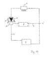
- Fig. 1 shows a hydraulic system in which a pump unit according to the Fig. 2 to 20 can be used.
- This hydraulic system is a heating system with two hydraulic circuits.
- the hydraulic system has a primary heat exchanger 2, which is heated, for example by a burner such as a gas or oil burner.
- the primary heat exchanger 2 is therefore for example a boiler, but it may also be another suitable heat generator.
- Located in the flow direction behind the primary heat exchanger 2 is a branch point 4, at which the circuit is divided into two branches or circles.
- a first circle 5 passes through a building for space heating and is symbolized by a radiator 6 in this example. It is to be understood that this heating circuit 5 may have more than one heating element 6 or other heating cables.
- the second hydraulic circuit 7 passes through a secondary heat exchanger 8, which serves to heat hot water.
- the heating circuit 5 and the second circuit 7 open into a valve 10, which is part of the pump unit 12.
- the pump unit 12 serves to convey water through the two circuits 5 and 7, wherein depending on the switching position of the switching valve designed as a valve 10, only one of the circles 5 and 7 is opened, while the other circle is closed. That is, during operation of the pump unit 12, the heated water from the primary heat exchanger 2 is conveyed either by the secondary heat exchanger 8 or by the radiator 6 depending on the valve position. It is essential that the outlet-side pressure of the pump unit 12 is applied via the branch point 4 in the closed circuit of the valve 10.
- In the pump unit 12 is a pump unit, which can be operated via an electric drive motor in two directions of rotation. The direction of rotation is from a control device 14, which is integrated in the pump unit 12 set. The control device 14 controls the electric drive motor.
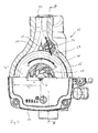
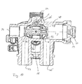
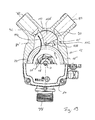
- Fig. 2 shows the pump housing 16 partially cut. In the uncut area, a plan view of the electronics housing housing the controller 14 is shown. Inside the pump housing 16, an impeller 18 is located. This is rotationally driven by the electric drive motor 20 about the rotation axis D. In this case, the impeller can be driven either in the directions of rotation A and B.
- the impeller 18 has a radius r 1 , while the inner diameter of the pump housing 16 in the peripheral region of the impeller 18 has a diameter r 2 . It can be seen that the inner diameter r 2 of the pump housing 16 is significantly larger than the outer diameter r 1 of the impeller.
- the radius of the pump housing r 2 is about twice as large as the radius r 1 of the impeller 18. In this way, a space in the form of an annular space 22 in the peripheral region of the impeller 18 is created, in which a upon rotation of the impeller 18 a forms rotating water ring, which increases in the radial direction during the rotation until the flow enters the outlet channel 24.
- the rotating water ring favors the implementation of flow energy, that is speed of the fluid exiting the impeller 18 in pressure.
- the impeller 18 has curved blades 26 which are curved both in the direction of the rotation axis D and in the circumferential direction.
- the blades 26 are curved so that they are optimized in the direction of rotation A. That is, the impeller will achieve the optimum efficiency when rotated in the direction A. Due to the free annular space 22, the impeller but also achieved in the Direction of rotation B, despite the not properly curved for this direction blades 26, an acceptable efficiency.
- the outlet channel 24 has two outlet channel sections 28 and 30 adjacent to the interior of the pump housing 16.
- the outlet channel sections 28 and 30 are separated from one another by a cross-sectionally triangular separating element 32 or a dividing wall 32. Downstream of the partition 32, the outlet channel sections 28 and 30 join to the outlet channel 24.
- the impeller 18 rotates in the direction of rotation A
- the liquid or water in the outer peripheral region of the impeller 18 in the annular space 22 will also rotate in the direction A and so on enter the outlet channel section 28 in a tangential direction, while significantly less water will enter the outlet channel section 30.
- the impeller 18 is operated in the opposite direction of rotation B, the liquid in the annular space 22 also rotates in the direction of rotation B, so that the liquid then preferably enters the outlet channel section 30.
- a drive element in the form of a pivotable flap 34 is arranged in the outlet channel section 28 in the outlet channel section 28 in the outlet channel section 28, a drive element in the form of a pivotable flap 34 is arranged.
- the flap is secured to a lever 36 which extends through a seal 38 from inside the pump housing 16 into the interior of a valve housing 40.
- the valve housing 40 is arranged on the suction side of the pump assembly 12 and accommodates the valve 10.
- the interior of the valve housing 40 is connected via a connection 42 indicated only schematically with a suction chamber and thus the suction mouth of the impeller 18 in connection.
- the valve housing 40 has two inlet channels 44 and 46, wherein the inlet channel 44 is connected to the heating circuit 5 and the inlet channel 46 to the second circuit 7 through the secondary heat exchanger 8.
- the valve has a linearly movable valve element 48, wherein the lever 36 is engaged with the valve element 48 such that pivotal movement of the lever 36 about a pivot axis S linearly displaces the valve element 48 along the axis Y.
- the valve element 48 has two facing sealing surfaces 50 and 52 at its axial ends. The sealing surfaces 50 and 52 facing valve seats 54 and 56. In this case, the first inlet channel 44 opens to the first valve seat 54 and the second inlet channel 46 at the second valve seat 56.
- the sealing surface 50 can be in sealing contact with the valve seat 54, while the sealing surface 52 can come into sealing contact with the valve seat 56, as in Fig. 3 is shown.
- the sealing surfaces 50, 52 are firmly connected to each other via the valve element 48, so that when one of the sealing surfaces 50, 52 abuts its associated valve seat 54, 56, the respective other sealing surface 52, 50 is lifted from its valve seat 56, 54.
- the inlet channels 44 and 46 communicates via the connection 42 with the suction mouth of the impeller 18 in fluid-conducting connection.
- Fig. 3 shows the rest position of the valve 48, which is held by a return spring 58.
- This rest position is the position of the valve element 58 at standstill of the pump unit.
- the second circuit 7 is closed by the secondary heat exchanger 8, since the inlet channel 46 is closed.
- the drive motor 20 is started by appropriate control via the control device 14 in such a way that the impeller 18 rotates in the direction of rotation B, the rotating flow is directed in the annular space 22 primarily in the outlet channel 30, so that on the flap 34 acts only a small flow force, which is not sufficient that the flap 34 pivots the lever 36 to move the valve element 48.
- the water is conveyed via the outlet channel section 30 into the outlet channel 34 and flows through the heating circuit 5 into the inlet channel 34. From there it flows through the open valve seat 54, At the same time, the output side pressure of the pump unit 12 is transmitted via the now closed second circuit 7 in the inlet channel 46 via the connection 42 in the suction port of the impeller 18. There, the pressure acts on the end face of the valve element 48, that is, the back of the sealing surface 52. Since the valve seat 56 is formed elastically, it is thereby deformed by a certain amount relative to the rest position, so that the valve element 48 is still a certain degree can move. During the operation of the pump unit, the pressure acting on the rear side of the sealing surface 52 through the inlet channel 46 holds the valve element 48 so securely in the shown first switching position, which serves to guide the heating water through the heating circuit 5.
- valve element is designed so that it must be moved to close the inlet channel 46 in the flow direction S 1 to the sealing seat 50. Conversely, the sealing surface 50 is moved in the flow direction S 2 through the inlet channel 44 to the valve seat 54 to close the valve seat 54.
- the valve element 48 extends through the valve seats 54 and 56 or in the openings enclosed by the valve seats 54 and 65, so that the sealing surfaces 50 and 52 face each other, while the valve seats 54 and 56 are facing away from each other.
- the liquid in the interior of the pump housing 16 in the annular space 22 is set in rotation in the direction of rotation A.
- the liquid now flows primarily into the outlet channel section 28, while less or substantially no flow is directed into the outlet channel section 30.
- the flap 34 is acted on at its impeller 18 facing surface, which forms an inflow surface, with the flow which pivots the flap 34 about the pivot axis S, whereupon the lever 36 at the same time the valve member 48 linearly displaced along the axis Y, wherein the sealing surface 52 of the valve seat 56 out of engagement and so the first inlet channel 46 releases.
- the drive motor is preferably accelerated by a control device such that the flow pivoting the flap 34 sets itself faster than a pressure prevailing in the inlet channel 46 and acting on the valve element 48. This ensures that the valve element 48 can be moved before a sufficient holding pressure builds up.
- the sealing surface 50 comes into contact with the valve seat 54 and closes the first inlet channel 44.
- the output-side pressure of the pump unit 12 is also transmitted through the closed heating circuit 5 into the first inlet channel 44, so that the pressure there acts on the rear side of the sealing surface 50 or on the end face of the valve element 48.
- the sealing surface 50 is pressed further against the valve seat 54, which deforms to a certain extent due to its elasticity.
- the valve element 48 is further linearly displaced, as it was moved solely by the pivotal movement of the flap 34 and the lever 36.
- the lever 36 is also moved via the coupling, and the flap 34 is pivoted substantially out of the flow path through the outlet channel section 30, so that the flow resistance is minimized. If the pump unit is turned off, the pressure on the end face of the valve element 48, which is formed by the back of the sealing surface 50, away and the return spring 58 moves the valve element 48 back into the in Fig. 3 shown starting position back.
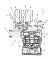
- Fig. 6 illustrates the assembly of the pump assembly 12.
- the pump housing 16 is integrally formed with the valve housing 40.
- the valve 10 is used as an insert in the valve housing 40 by a Opening 59 inserted, which is subsequently closed by a cover 57.
- the return spring 58 is supported at one end on the valve element 48 and at the opposite end on the inside of the lid 57 from.
- the flap 34 with the lever 36 and the seal 38 can be used with the drive motor 20 removed by the drive motor 20 facing opening of the pump housing 16.
- Fig. 7 to 12 show a variant of the pump unit 12, as described above. The following description will essentially deal with the differences.
- the arrangement of the impeller 18 in the pump housing 16 with the surrounding annular space 22 corresponds to the embodiment in the preceding embodiment.
- the outlet channel 24 also expands towards the interior of the pump housing 16, so that outlet channel sections 28 and 30 are formed, which are not separated by a solid wall, but by a flap 60, which serves here as a drive element.
- the flap 60 has an inflow surface 62 on one side and a second inflow surface 44 on the opposite side. If the impeller 18 rotates in the direction of rotation 17, the flow is directed mainly into the outlet channel section 28 and flows to the inflow surface 64, while upon rotation of the impeller in the direction of rotation B, the flow is directed primarily into the outlet channel section 30 and the inflow surface 62 flows to. If the inflow surface 62 is flown, the flap 60 pivots about the pivot axis C in the direction b. When the inflow surface 64 is flown, the flap 60 is pivoted about the pivot axis C in the direction a.
- the flap 60 is rotatably connected to a shaft 66 which extends through a shaft seal 68 into the valve housing 14.
- the shaft seal 68 can be dispensed with if the fit in the leadthrough for the shaft 66 has been selected accordingly and / or if necessary a certain leakage can be tolerated.
- the shaft seal 56 is formed directly from the wall of the pump housing or the valve housing 40.
- the shaft 66 terminates on a lever arm 70, which extends from the shaft 66 with respect to the pivot axis C diametrically opposite to the flap 60.
- the lever arm 70 engages with a pin 72 in the valve element 48 a.
- valve 10 is also in this embodiment, as in Fig. 8 can be seen, formed as an insert 10, which is inserted through the opening 59 in the valve housing 40.
- the valve housing 40 at the opposite end of the opening 59 for mounting purposes nor a port 74, which, as in Fig. 7 shown closed by a cap 76.
- Fig. 9 shows a rest position of the flap 62, in which it extends substantially radially to the axis of rotation D of the impeller 18. It can be seen that the flap 62 as well as the flap 34 is located completely outside of the free annular space 22, that is with its radially inner end as far from the outer periphery of the impeller 18 as the inner wall of the pump housing 16 in the peripheral region of the Impeller 18.
- the valve element 48 of the valve 10 which is formed substantially as in the first embodiment, in the in Fig. 10 shown center position in which the sealing surface 52 are lifted from the valve seat 56 and the sealing surface 50 of the valve seat 54. In this situation are thus initially open both inlet channels 44 and 46.
- the flap 60 pivots as described in the direction b until it comes to rest against the wall of the outlet channel 24, preferably under elastic deformation.
- the valve element 18 in the in Fig. 11 shown shifted switching position, in which the sealing surface 50 comes to the valve seat 54 in sealing contact.
- the inlet duct 44 which is connected to the heating circuit 5, is closed.
- the output pressure of the pump unit 12 now also acts on the end face of the valve element 48 on the rear side of the sealing surface 50 via the inlet channel 44, so that the valve element 48 is displaced further in the axial direction with elastic deformation of the valve seat 54.
- the flap 60 springs back due to an elastic deformation when it rests against the wall of the outlet channel 24.
- the relaxation of the sealing seat 54 also causes a restoring force.
- the flap 60 pivots as described in the direction a until it comes to rest on the wall of the outlet channel 24 and the valve element 48 is inserted into the in Fig. 12 shown second switching position moves in which the sealing surface 50 is lifted from the valve seat 54 and the sealing surface 52 of the valve element 48 comes to the sealing seat 56 to the plant.
- the intake passage 46 is closed while the intake passage 44 is opened.
- the flow path through the heating circuit 5 is opened and the flow path through the circuit 7 and the secondary heat exchanger 8 is closed.
- the suction mouth or inlet 77 (see 10 to 12 ) of the impeller 18 in all the embodiments described herein preferably has a diameter between 12 and 30 mm, more preferably between 12 and 25 mm, while the radius r 1 of the impeller 18 is preferably between 12 and 30 mm.
- valve 10 was arranged on the suction side of the pump unit 12 and actuated by a drive element in the form of a flap 34 or a flap 60 which was arranged on the pressure side of the pump unit 12, according to the following embodiments, which reference of the Fig. 13 to 21 be explained, the valve 10 'on the pressure side of the pump unit 12 is arranged.
- Fig. 13 shows a corresponding hydraulic system with such a pump unit 12.
- the pump unit 12 via its control device 14 in two different directions A and B can be driven, the valve 10 'depending on the direction of rotation A, B, the flow path either through the heating circuit 5 or the flow path through the heat exchanger 8 turns on.
- the two heating circuits branch 5 and 7 at the valve 10 'and flow again at the branch point 4' and from there through the primary heat exchanger 2 back to the pump unit 12th
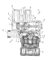
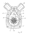
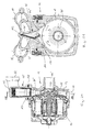
- FIGS. 14 to 16 show a first embodiment of a suitably designed pump unit 12 with a valve 10 '.
- the design of the pump housing 16 with the impeller 18 disposed therein, which is driven by a drive motor, not shown here, corresponds to the embodiment, as they are based on Fig. 2 was explained.
- the radius r 2 of the inner diameter of the pump casing 16 in the peripheral region of the impeller 18 is significantly greater than the radius r 1 of the impeller 18.
- the radius r 2 is about twice as large as the radius r. 1
- a free annular space 22 surrounding the impeller 18 is also formed here, in which a rotating liquid ring can form when the impeller 18 rotates.
- the blades 26 of the impeller 18 curved in the manner as shown by Fig. 2 was explained.
- this pump unit 12 has only one inlet channel 78, which is in communication with the suction mouth of the impeller 18.
- pump unit 12 has two outlet channels 80 and 82.
- the heating circuit 8 extends and to the outlet 82, the second circuit 7 connects through the secondary heat exchanger 8.
- the two outlet channels 80 and 82 branch off from a common outlet space 84.
- Exhaust space 84 is formed on the inner circumference of the pump housing 16 and extends radially outward.
- the outlet space 84 has a substantially triangular shape normal to the axis of rotation D of the impeller 18, wherein it tapers radially outwards starting from its inlet end facing the impeller 18.
- the discharge space 84 is outside the annulus 22.
- the discharge space 84 is further formed symmetrically to a center axis Z which extends normal to the rotation axis D.
- the outlet channels 80 and 82 branch off from two opposite and at an acute angle to each other extending side surfaces 86 and 88 from.
- the outlet channel 80 has in the side surface 86 an inlet opening 90 and the outlet channel 82 has an inlet opening 92 in the side surface 88.
- the side surfaces 86 and 88 form in the peripheral region of the inlet openings 90 and 92 a valve seat.
- a valve element in the form of a pivotable flap 94 is arranged in the outlet space 84.
- the flap 94 is formed of an elastically bendable material and fixed with its end edge 96 facing away from the impeller 18 in the housing in the contact area of the side surfaces 86 and 88.
- the flap 94 can pivot by bending in the directions a and b in the outlet space 84.
- the impeller facing the end edge 98 of the flap 94 is also outside the annular space 22, that is substantially the same distance from the outer circumference of the impeller 18 as the inner circumference of the pump housing 16. D. h. the distance to the axis of rotation D is also substantially r 2 .
- the two opposite side surfaces 100 and 102 of the flap 94 form inflow surfaces on which the flow generated by the impeller 18 during its rotation acts.
- the impeller rotates in the direction of rotation A
- the resulting liquid which also rotates in the direction of rotation A in the annular space 22 acts mainly on the inflow surface 100, so that the flap 94 pivots in the direction a.
- a circumferential flow in the annular space 22 is also generated in the direction B.
- This flow enters the outlet space 84 so that it acts substantially on the opposite upstream surface 102, so that the flap 94 is deflected in the direction b.
- the deflection is done by bending the flap 94, so that in the flap 94 elastic restoring forces are generated, which the flap 94 at standstill of the impeller 18 back into the in Fig. 14 move shown center or rest position.
- the impeller 18 rotates counter to its optimized direction, ie, opposite to the direction for which the curvature of the blades 26 is optimized.
- the large annular space 22 while the efficiency can be improved, even if the efficiency in this state may be less than in the direction of rotation A, so that it lends itself to use this direction of rotation for the second circuit 7 through the secondary heat exchanger 8, since this circle is operated in a heating system in time to a much lesser extent than the heating circuit 5.
- the efficiency difference between the directions of rotation is low.
- the impeller 18 is rotated by appropriate control of the drive motor in the direction of rotation A, as in Fig. 16 is shown pivoted the flap 94 in the direction a, so that the surface of the flap 94, which forms the inflow surface 102, sealingly comes to rest on the circumference of the inlet opening 92 and the inlet opening 92 and thus the outlet channel 82 closes.
- the inlet opening 90 and thus the outlet channel 80 are opened.
- the flow from the annular space 22 is thus directed via the outlet 94 in the outlet channel 80 and thus in the subsequent heating circuit 5, while the second circuit 7 is closed by the secondary heat exchanger 8.
- the impeller 18 rotates in its preferred running direction, for which the curvature of the blades 26 is optimized, so that in this state a particularly high efficiency is achieved.
- Fig. 17 shows a pump housing 16 ', which is slightly modified from the pump housing 16 described above.
- the valve 10 'in the embodiment according to Fig. 17 is designed in the same way as based on the Fig. 14 to 16 explained.
- the embodiment according to Fig. 17 is only the annular space 22 'relative to the annular space 22, as described above, modified.
- the annular space 22 'does not extend over the full circumference of the impeller 18 with a constant width, but has on two diametrically opposite sides radially enlarged peripheral portions 104, which adjoin the outlet space 84.
- the radius r 2 'of the inner periphery of the pump housing 16' is substantially twice the radius r 1 of the impeller 18.
- the radius of the inner circumference of the Pump housing 16 ' In the diametrically opposite to the outlet chamber 84 located peripheral portion of the pump housing 16 'is the radius of the inner circumference of the Pump housing 16 ', however, smaller.
- no completely uniformly expanded annular space 22 is created.
- the radially inner end 98 of the flap 94 is also spaced from the outer circumference of the impeller 18, substantially the same extent as the inner peripheral surface of the pump housing 16 'in the peripheral portions 104.
- the Fig. 18 and 19 show a modification of the pump unit 12 according to Fig. 13 to 16
- the embodiment according to Fig. 18 and 19 differs in the design of the valve 10 '.
- the pump housing 16, the impeller 18 with the blades 26 and the annular space 22 correspond to the embodiment, as they are based on the Fig. 13 to 16 were explained. In this respect, reference is made to this description.
- the outlet space 84 ' has a somewhat modified shape. He has no triangular basic shape.
- a substantially circular segment-shaped or "pie-shaped" valve element 106 is arranged in the outlet space 84.
- the valve element 106 is pivotable about a pivot axis 108, which extends parallel to the axis of rotation D of the impeller 18.
- the pivot axis 108 lies against the end of the valve element 106 which faces in the impeller 18, ie essentially at the tip of the sector shape.
- the pivot axis 108 is spaced from the outer circumference of the impeller 18, substantially the same distance as the inner peripheral wall of the pump housing 16, that is substantially to the radius r 2 , spaced as he is based on Fig. 14 has been described.
- the valve element 106 has an end face 110, which faces away from the pivot axis 108 and is curved in cross-section, which extends concentrically with respect to the pivot axis 108.
- the end face 110 forms a sealing surface of the valve element 106.
- the end face 110 connecting with the region of the pivot axis 108 has the valve element 106 two side faces 112 and 114 facing away from each other and at an acute angle.
- the side surfaces 112 and 114 form inflow surfaces and are concavely curved transversely to the pivot axis 108 in the cross section shown. Thus, they can form a curved flow channel together with the side surfaces of the outlet space 84 '.
- the outlet channels 80 and 82 have inlet openings adjacent to the outlet space 84 ' 90 and 92, wherein the inlet openings 90 and 92 in a cross-sectionally arcuate outer wall 116 of the outlet space 84 'are located.
- the outer wall 116 has substantially the same radius of curvature as the end face 110 or extends radially from the end face 110 concentrically with the pivot axis 108, so that the end face 110 is guided parallel to the outer wall 116 when the valve element 106 is pivoted.
- the end face 110 can come into sealing contact with the peripheral areas of the inlet openings 90 and 92 in order to close them.
- Fig. 18 shows a first switching position of the valve element 106. This switching position is achieved when the impeller 18 rotates in the direction of rotation A. Then, the generated flow acts on the inflow surface 112, so that the valve element 106 is pivoted in the direction a so far that the end face 110 closes the inlet opening 92. At the same time, the end face 110 comes out of the inlet opening 90, so that the inlet opening 90 is released and the flow into the outlet channel 80 and from there into the heating circuit 5 can occur. If the impeller 18 is rotated in the opposite direction of rotation B, as in Fig.
- the flow acts on the inflow surface 114 and the valve element 106 is pivoted about the pivot axis 108 in the direction b, so that the end face 110 covers the inlet opening 90 and closes the outlet channel 80 and at the same time releases the inlet opening 92 with the outlet channel 82, so that the flow is directed into the second circuit 7 through the secondary heat exchanger 8.
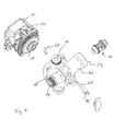
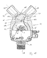
- FIGS. 20 and 21 show a further variant of the valve 10 'in the pump unit 12.
- the basic embodiment corresponds to the basis of the Fig. 13 to 16 explained embodiment. That in the FIGS. 20 and 21 Pump unit shown has a drive motor 20, as in the embodiments 13 to 19 use but not shown in the figures there.
- the drive motor 20 is connected to the pump housing 16.
- Fig. 20 the electronics housing or the control device 14 is not shown.
- an impeller 18 is arranged in the same manner as with reference to Fig. 13 explained, so that the annular clearance 22 is formed in the interior of the pump housing 16.
- FIGS. 20 and 21 shown embodiment in the form of the outlet chamber 84 'and the valve element, which is designed here as an elastic sail 118.
- the valve element 118 is made of an elastic material and extends in the outlet space 84 "between the inlet openings 90 'and 92' of the outlet channels 80 and 82.
- the inlet openings 90 'and 92' are similar to the inlet openings 90 and 92 in the previous one Embodiment according to Fig. 13 to 16 ,
- the valve element 118 in the form of an elastic sail is fixed both at its end 120 facing the impeller 18 and at its end 122 facing away from the impeller 18.
- the surfaces of the valve element 108 extend in planes parallel to the axis of rotation D of the impeller 18. It has between the ends of such a length that it either to the inlet opening 92 ', as in Fig. 21 can turn, so that the inlet opening 92 'is closed, or can turn in the opposite direction to the inlet opening 90' out to close it.
- the turnover takes place in each case depending on whether the flow is generated by rotation of the impeller 18 in the direction of rotation A or in the direction of rotation B. If the impeller 18 rotates in the direction of rotation A, the valve element 118 is pressed against the inlet opening 92 'by the generated flow so that it is closed and the flow flows through the inlet opening 90' into the outlet channel 80.
- valve element 118 deflects due to the flow acting on its surface and thus closes the inlet opening 90 ', wherein the inlet opening 92 'is released and the flow flows into the outlet channel 82.
Abstract
Die Erfindung betrifft ein Pumpenaggregat (12) mit einem Pumpengehäuse, einem in dem Pumpengehäuse (16; 16')drehbar angeordneten Laufrad (18), einem mit dem Laufrad (18) verbundenen elektrischen Antriebsmotor (209, welcher wahlweise in zwei Drehrichtungen (A, B) antreibbar ist, sowie zumindest einem Ventil (10; 10') mit zumindest einem Ventilelement (106), welches von der von dem Laufrad (18) erzeugten Strömung abhängig von der Drehrichtung(A, B) des Laufrades (18) in zwei verschiedene Schaltstellungen bewegbar ist, wobei das ein Radius (r 2 ; r 2 ') des Pumpengehäuses z(16, 16') zumindest in einem Umfangsabschnitt (104) im Umfangsbereich des Laufrades (18) zumindest 1,4 mal und vorzugsweise zumindest 2 mal so groß wie der Radius (r 1 ) des Laufrades (18) ist, sowie ein hydraulisches System mit zumindest zwei hydraulischen Kreisen und einem solchen Pumpenaggregat (12), wobei das Ventil (10, 10') als Umschaltventil zwischen den zwei hydraulischen Kreisen ausgebildet ist.The invention relates to a pump unit (12) having a pump housing, an impeller (18) rotatably mounted in the pump housing (16; 16), an electric drive motor (209) connected to the impeller (18) and optionally in two directions of rotation (A, B), and at least one valve (10, 10 ') with at least one valve element (106), which depends on the direction of rotation (A, B) of the impeller (18) generated by the impeller (18) in two various switch positions is movable, wherein the one radius (r 2, r 2 ') of the pump housing z (16, 16') at least in a peripheral portion (104) in the peripheral region of the impeller (18) at least 1.4 times, and preferably at least 2 times as large as the radius (r 1) of the impeller (18), and a hydraulic system with at least two hydraulic circuits and such a pump unit (12), wherein the valve (10, 10 ') formed as a switching valve between the two hydraulic circuits is.
Description
Die Erfindung betrifft ein Pumpenaggregat mit einem Ventil sowie ein hydraulisches System mit einem solchen Pumpenaggregat.The invention relates to a pump unit with a valve and a hydraulic system with such a pump unit.
Beispielsweise aus
Nachteilig bei diesen bekannten bidirektionalen Pumpen ist, dass der Wirkungsgrad schwer zu optimieren ist. Wenn das Laufrad radial gerichtete Schaufeln aufweist, ist der Wirkungsgrad in beiden Drehrichtungen gleich, jedoch nicht optimal. Wenn das Laufrad, wie bei modernen Umwälzpumpen üblich, gekrümmte Schaufeln aufweist, wird dadurch der Wirkungsgrad in einer Drehrichtung verbessert, in der anderen Drehrichtung jedoch verschlechtert. So kann ein solches Pumpenaggregat nur in einer Drehrichtung einen optimalen Wirkungsgrad liefern.A disadvantage of these known bidirectional pumps is that the efficiency is difficult to optimize. If the impeller has radially directed blades, the efficiency is the same in both directions, but not optimal. If the impeller, as is common in modern circulation pumps, has curved blades, thereby the efficiency is improved in one direction, but deteriorated in the other direction of rotation. Thus, such a pump unit can deliver optimal efficiency only in one direction.
Im Hinblick auf diese Problematik ist es Aufgabe der Erfindung, ein Pumpenaggregat dahingehend zu verbessern, dass in beiden Drehrichtungen ein akzeptabler Wirkungsgrad erreicht werden kann.In view of this problem, it is an object of the invention to improve a pump unit to the effect that in both directions an acceptable efficiency can be achieved.
Diese Aufgabe wird gelöst durch ein Pumpenaggregat mit den in Anspruch 1 angegebenen Merkmalen sowie durch ein hydraulisches System mit den in Anspruch 20 angegebenen Merkmalen. Bevorzugte Ausführungsformen ergeben sich aus den Unteransprüchen, der nachfolgenden Beschreibung sowie den beigefügten Figuren.This object is achieved by a pump unit having the features specified in claim 1 and by a hydraulic system with the features specified in
Das erfindungsgemäße Pumpenaggregat ist ein Kreiselpumpenaggregat und weist ein Pumpengehäuse auf, in welchem ein Laufrad drehbar angeordnet ist. Das Laufrad wird durch einen mit ihm verbundenen elektrischen Antriebsmotor angetrieben. Dabei ist der elektrische Antriebsmotor so ausgebildet, dass er in zwei Drehrichtungen laufen kann. Es ist eine entsprechende Steuereinrichtung vorgesehen, welche den Antriebsmotor wahlweise in einer der beiden Drehrichtungen ansteuert. Das Pumpenaggregat weist ferner zumindest ein Ventil mit zumindest einem Ventilelement auf. Dieses Ventil kann vorzugsweise in das Pumpengehäuse integriert sein oder direkt an dem Pumpengehäuse in einem eigenen Gehäuse angeordnet sein. Besonders bevorzugt sind ein Ventilgehäuse und das Pumpengehäuse einstückig ausgebildet, beispielsweise als Gussbauteil, insbesondere Spritzgussbauteil aus Kunststoff.The pump unit according to the invention is a centrifugal pump unit and has a pump housing, in which an impeller is rotatably arranged. The impeller is driven by an electric drive motor connected to it. In this case, the electric drive motor is designed so that it can run in two directions of rotation. There is a corresponding control device is provided, which selectively drives the drive motor in one of the two directions of rotation. The pump unit also has at least one valve with at least one valve element. This valve may preferably be integrated into the pump housing or be arranged directly on the pump housing in a separate housing. Particularly preferably, a valve housing and the pump housing are integrally formed, for example as a cast component, in particular injection molded plastic.
Das Ventilelement des Ventils wird durch die von dem Laufrad erzeugte Strömung bewegt. Dazu ist das Ventilelement entsprechend in dem Pumpengehäuse angeordnet, so dass es von der von dem Laufrad erzeugten Strömung beaufschlagt wird. Dabei ist das Ventilelement so angeordnet, dass es in Abhängigkeit von der Drehrichtung des Laufrades in zwei verschiedene Schaltstellungen bewegbar ist. Durch die Rotation des Laufrades in dem Pumpengehäuse wird die aus dem Laufrad radial austretende Flüssigkeit zusätzlich in Umfangsrichtung beschleunigt. Das heißt im Pumpengehäuse entsteht eine in Umfangsrichtung des Laufrades rotierende Strömung. Diese Strömung rotiert in der Drehrichtung des Laufrades. Durch Änderung der Drehrichtung des Laufrades kann somit auch die Strömungsrichtung der rotierenden Strömung geändert werden. Bei entsprechender Anordnung des Ventilelementes kann dies somit bei den unterschiedlichen Drehrichtungen unterschiedlich von der Strömung beaufschlagt werden, so dass das Ventilelement durch die verschiedenen Strömungsrichtungen wahlweise in die zwei verschiedenen Schlafstellungen bewegt werden kann.The valve element of the valve is moved by the flow generated by the impeller. For this purpose, the valve element is arranged correspondingly in the pump housing, so that it is acted upon by the flow generated by the impeller. In this case, the valve element is arranged so that it can be moved in two different switching positions depending on the direction of rotation of the impeller. Due to the rotation of the impeller in the pump housing, the radially emerging from the impeller fluid is additionally accelerated in the circumferential direction. That is, in the pump housing creates a rotating in the circumferential direction of the impeller flow. This flow rotates in the direction of rotation of the impeller. By changing the direction of rotation of the Impeller can thus be changed, the flow direction of the rotating flow. With an appropriate arrangement of the valve element, this can thus be applied differently in the different directions of rotation of the flow, so that the valve element can be moved by the different flow directions either in the two different sleeping positions.
Erfindungsgemäß sind das Pumpengehäuse und das Laufrad so ausgebildet und relativ zueinander so dimensioniert, dass in zumindest einem Umfangsabschnitt, bezogen auf die Drehachse des Laufrades, zwischen dem Außenumfang des Laufrades und dem Pumpengehäuse ein vergleichsweise großer Freiraum ausgebildet ist. Dazu sind Pumpengehäuse und Laufrad so dimensioniert, dass ein Radius des Pumpengehäuses, d.h. des Innenumfanges des Pumpengehäuses, in diesem Umfangsabschnitt im Umfangsbereich des Laufrades zumindest 1,4 mal und vorzugsweise zumindest 1,5 oder zumindest 2 mal so groß wie der Radius des Laufrades ist. Der Radius des Pumpengehäuses ist dabei der Abstand der Innenwandung des Pumpengehäuses von der Drehachse des Laufrades. Der dadurch gebildete Abstand bzw. Freiraum zwischen dem Außenumfang des Laufrades und der umgebenden Innenwandung des Pumpengehäuses verbessert die Strömungsführung im Inneren des Pumpengehäuses am Austritt des Laufrades. Dies gilt insbesondere dann, wenn das Laufrad für eine Drehrichtung optimiert ist. Dann wird die Wirkung des Laufrades in der entgegengesetzten Drehrichtung, für welche es nicht optimiert ist, durch den entstehenden Freiraum deutlich verbessert, so dass auch in dieser "falschen" Drehrichtung ein verbesserter Wirkungsgrad erzielt werden kann. Die Innenkontur des Pumpengehäuses muss nicht zwingend einen kreisförmigen Querschnitt haben, vielmehr kann der Radius über den Umfang variieren. Durch die erfindungsgemäße Ausgestaltung des Pumpengehäuses ist es möglich Druck-Mengen-Kurven zu erzielen, welche in beiden Drehrichtungen im Wesentlichen identisch sind.According to the invention, the pump housing and the impeller are designed and dimensioned relative to one another such that a comparatively large clearance is formed in at least one circumferential section, relative to the axis of rotation of the impeller, between the outer circumference of the impeller and the pump housing. For this purpose, the pump housing and impeller are dimensioned so that a radius of the pump housing, ie the inner circumference of the pump housing, in this peripheral portion in the peripheral region of the impeller at least 1.4 times, and preferably at least 1.5 or at least 2 times as large as the radius of the impeller , The radius of the pump housing is the distance of the inner wall of the pump housing from the axis of rotation of the impeller. The resulting distance or clearance between the outer periphery of the impeller and the surrounding inner wall of the pump housing improves the flow guidance in the interior of the pump housing at the outlet of the impeller. This is especially true when the impeller is optimized for one direction of rotation. Then, the effect of the impeller in the opposite direction of rotation, for which it is not optimized, significantly improved by the resulting clearance, so that even in this "wrong" direction of rotation improved efficiency can be achieved. The inner contour of the pump housing does not necessarily have a circular cross section, but the radius can vary over the circumference. The inventive design of the pump housing, it is possible to achieve pressure-quantity curves, which are essentially identical in both directions of rotation.
In dem genannten Umfangsabschnitt, in welchem der Freiraum ausgebildet ist, ist der radiale Abstand zwischen dem Außenumfang des Laufrades und der gegenüberliegenden Innenwandung des Pumpengehäuses vorzugsweise an jeder Stelle so groß, wie es sich durch die zuvor genannten Größenverhältnisse von Laufrad und Pumpengehäuse in diesem Bereich ergibt. Das heißt der Freiraum ist vorzugsweise durch keinerlei Vorsprünge oder ähnliches gestört, so dass in diesem Bereich keine Hindernisse für die Strömung bestehen. Insbesondere erstreckt sich auch kein Teil des Ventils oder Ventilelementes in diesen Freiraum hinein.In the said peripheral portion, in which the free space is formed, the radial distance between the outer circumference of the impeller and the opposite inner wall of the pump housing is preferably at any point as large as it results from the aforementioned proportions of impeller and pump housing in this area , That is, the free space is preferably disturbed by any projections or the like, so that there are no obstacles to the flow in this area. In particular, no part of the valve or valve element extends into this space.
Gemäß einer bevorzugten Ausführungsform der Erfindung ist der Radius des Pumpengehäuses in dem genannten Umfangsabschnitt mindestens 2,5 oder mindestens 3 mal so groß, wie der Radius des Laufrades. Gemäß einer weiteren bevorzugten Ausführungsform ist der Radius des Pumpengehäuses in diesem Umfangsabschnitt zwischen 1,5 und 3,5 mal so groß und weiter bevorzugt zwischen 1,75 und 2,25 mal so groß wie der Radius des Laufrades. In diesen Größenverhältnissen werden besonders günstige Strömungsverhältnisse erzielt.According to a preferred embodiment of the invention, the radius of the pump housing in said peripheral portion is at least 2.5 or at least 3 times as large as the radius of the impeller. According to a further preferred embodiment, the radius of the pump housing in this peripheral portion is between 1.5 and 3.5 times as large and more preferably between 1.75 and 2.25 times the radius of the impeller. In these proportions particularly favorable flow conditions are achieved.
Wie beschrieben ist es möglich, dass sich der genannte erweiterte Umfangsabschnitt, in welchem ein vergrößerter Freiraum zwischen Laufrad und gegenüberliegender Innenwandung des Pumpengehäuses ausgebildet ist, nur über einen begrenzten Winkelbereich im Umfang des Laufrades erstreckt. Vorzugsweise erstreckt sich der Umfangsabschnitt zumindest über 45° des Umfanges bezogen auf die Drehachse des Laufrades. Weiter bevorzugt erstreckt sich der Umfangsabschnitt zumindest über 90° und noch weiter bevorzugt über mindestens 180° des Umfanges bezogen auf die Drehachse des Laufrades. Gemäß einer besonders bevorzugten Ausführungsform ist im gesamten Umfangsbereich des Laufrades, das heißt über 360° ein derartiger Freiraum zwischen dem Außenumfang des Laufrades und der gegenüberliegenden Innenwandung des Pumpengehäuses gemäß der vorangehenden Definitionen der Größenverhältnisse zwischen Radius des Laufrades und Radius des Pumpengehäuses gegeben. Vorteilhaft ist ein solcher ringförmiger Freiraum im gesamten Umfang des Laufrades, in welchem insbesondere auch keine Teile von Ventilelementen hinein ragen, derart ausgebildet, dass bei Rotation des Laufrades im Umfang des Laufrades ein sich drehender Wasserring bzw. Flüssigkeitsring ausgebildet werden kann. Der ringförmige Freiraum, welcher sich über den gesamten Umfang des Laufrades erstreckt, muss keine konstante Breite in radialer Richtung und keine konstante Höhe in axialer Richtung aufweisen. Diese Maße können vielmehr über den Umfang variieren. Wesentlich ist lediglich, dass der Freiraum so groß dimensioniert ist, dass sich ein um die Drehachse des Laufrades rotierender Wasserring ausbilden kann. Ein solcher rotierender Wasserring hat die Wirkung einer zweiten nachfolgenden Pumpenstufe und unterstützt die Umwandlung der durch die Geschwindigkeit der aus dem Laufrad austretenden Flüssigkeit bedingten kinetischen Energie in Druck. Der rotierende Wasserring hat somit eine ähnliche Wirkung einer Spirale im Pumpengehäuse oder eines Leitapparates im Pumpengehäuse. Aus diesem Wasserring tritt die Flüssigkeit dann in einen am Außenumfang des Pumpengehäuses angeordneten Auslass in radialer und/oder tangentialer Richtung aus. Insgesamt vollzieht die Flüssigkeit nach dem Austritt aus dem Laufrad somit eine kreis- bzw. spiralförmige Bewegung im Inneren des Pumpengehäuses. Die Ausbildung eines solchen Wasserringes unterscheidet sich somit grundsätzlich von konventionellen Kreiselpumpen, bei welchen die Ausbildung eines solchen rotierenden Wasserringes gerade verhindert werden soll. In konventionellen Kreiselpumpen ist das Pumpengehäuse im Umfang des Laufrades in der Regel so gestaltet, dass in Drehrichtung hinter dem Auslass des Pumpengehäuses ein radial nach innen gerichteter Vorsprung oder eine Zunge vorgesehen ist, welche die Rotation der Flüssigkeit über den Auslass hinaus verhindert.As described, it is possible that said enlarged peripheral portion, in which an enlarged clearance between the impeller and the opposite inner wall of the pump housing is formed, extends only over a limited angular range in the periphery of the impeller. Preferably, the peripheral portion extends at least over 45 ° of the circumference with respect to the axis of rotation of the impeller. More preferably, the peripheral portion extends at least over 90 ° and even more preferably over at least 180 ° of the circumference with respect to the axis of rotation of the impeller. According to a particularly preferred embodiment, in the entire peripheral region of the impeller, that is to say over 360 °, such a free space is provided between the outer circumference of the impeller and the opposite one Inner wall of the pump housing according to the foregoing definitions of the size ratios between the radius of the impeller and radius of the pump housing given. Advantageously, such an annular clearance in the entire circumference of the impeller, in which in particular also no parts of valve elements protrude, designed such that upon rotation of the impeller in the periphery of the impeller, a rotating water ring or liquid ring can be formed. The annular clearance, which extends over the entire circumference of the impeller, need not have a constant width in the radial direction and no constant height in the axial direction. These dimensions may vary over the circumference. It is only essential that the free space is dimensioned so large that can form a rotating about the axis of rotation of the impeller water ring. Such a rotating water ring has the effect of a second subsequent pump stage and helps to convert the kinetic energy due to the velocity of the liquid leaving the impeller into pressure. The rotating water ring thus has a similar effect of a spiral in the pump housing or a nozzle in the pump housing. From this water ring, the liquid then exits into a arranged on the outer circumference of the pump housing outlet in the radial and / or tangential direction. Overall, the liquid thus completes after leaving the impeller a circular or spiral movement in the interior of the pump housing. The formation of such a water ring thus differs fundamentally from conventional centrifugal pumps, in which the formation of such a rotating water ring is just to be prevented. In conventional centrifugal pumps, the pump housing in the periphery of the impeller is usually designed so that in the direction of rotation behind the outlet of the pump housing, a radially inwardly directed projection or a tongue is provided, which prevents the rotation of the liquid beyond the outlet.
In dem genannten Umfangsabschnitt, in welchem der oben beschriebene vergrößerte Freiraum zwischen dem Außenumfang des Laufrades und der gegenüberliegenden Innenwandung des Pumpengehäuses gegeben ist, hat dieser Freiraum in axialer Richtung parallel zur Drehachse des Laufrades vorzugsweise eine Höhe, welche zumindest der Höhe der Austrittsöffnungen am Außenumfang des Laufrades in dieser Richtung entspricht. So kann die Höhe beispielsweise mindestens zwischen 3 und 6 mm liegen. Wenn auf diese Weise ein Ringraum im Umfang des Laufrades ausgebildet ist, so weist dieser Ringraum vorzugsweise über den gesamten Umfang eine solche Höhe in axialer Richtung auf. Wenn nur kleinere Umfangsabschnitte in der beschriebenen Weise in radialer Richtung verbreitert ausgebildet sind, ist es möglich, dass die in radialer Richtung schmaler ausgebildeten Umfangsabschnitte eine größere Höhe in axialer Richtung parallel zur Drehachse des Laufrades haben.In said peripheral portion, in which the above-described increased clearance between the outer periphery of the impeller and the opposite inner wall of the pump housing is given, this clearance in the axial direction parallel to the axis of rotation of the impeller preferably has a height which at least the height of the outlet openings on the outer periphery of the Impeller in this direction corresponds. For example, the height can be at least between 3 and 6 mm. If in this way an annular space is formed in the periphery of the impeller, then this annular space preferably has such a height in the axial direction over the entire circumference. If only smaller peripheral portions are widened in the manner described in the radial direction, it is possible that the narrower in the radial direction formed peripheral portions have a greater height in the axial direction parallel to the axis of rotation of the impeller.
Das Laufrad ist vorzugsweise so dimensioniert, dass es einen Durchmesser zwischen 25 und 60 mm aufweist, wobei der Einlauf-Durchmesser bzw. Saugmund-Durchmesser vorzugsweise zwischen 12 und 30 mm liegt. Dies bedeutet, dass es sich vorzugsweise bei dem Laufrad um ein im Durchmesser relativ kleines Laufrad handelt. Bevorzugt wird ein solches Laufrad von dem elektrischen Antriebsmotor in zumindest einer, vorzugsweise in beiden Drehrichtungen mit einer relativ hohen Betriebsdrehzahl angetrieben, welche bevorzugt größer als 3.000, weiter bevorzugt größer als 5.000 Umdrehungen pro Minute ist. So kann die Drehzahl beispielsweise im Bereich zwischen 3.000 und 7.000 Umdrehungen pro Minute liegen und gegebenenfalls in diesem Bereich durch Drehzahlregelung zur Regelung des Pumpenaggregates variiert werden. Vorzugsweise ist das Pumpenaggregat ferner so ausgebildet, dass das erzielte Druck-Mengen-Verhältnis größer als 3/1, weiter bevorzugt größer 4/1 oder größer 5/1 ist. Das Druck-Mengen-Verhältnis kann bis zu 8/1 oder mehr betragen. Das genannte Druck-Mengen-Verhältnis basiert auf einem als Förderhöhe in Metern angegebenen Druck und einer Menge in Form des Durchflusses in Kubikmetern pro Stunde. Zusammen mit der genannten Betriebsdrehzahl kann so vorzugsweise eine spezifische Drehzahl nq zwischen 20 und 40, gegebenenfalls auch größer 40 erreicht werden.The impeller is preferably dimensioned so that it has a diameter between 25 and 60 mm, wherein the inlet diameter or suction mouth diameter is preferably between 12 and 30 mm. This means that it is preferably the impeller is a relatively small diameter impeller. Preferably, such an impeller is driven by the electric drive motor in at least one, preferably in both directions of rotation with a relatively high operating speed, which is preferably greater than 3,000, more preferably greater than 5,000 revolutions per minute. For example, the speed may be in the range between 3,000 and 7,000 revolutions per minute and may be varied in this range by speed control for regulating the pump unit. Preferably, the pump unit is further designed so that the achieved pressure-quantity ratio is greater than 3/1, more preferably greater than 4/1 or greater than 5/1. The pressure to volume ratio can be up to 8/1 or more. The mentioned pressure-quantity ratio is based on a pressure specified as head in meters and an amount in terms of flow in cubic meters per hour. Together with the aforementioned operating speed, a specific rotational speed nq between 20 and 40, possibly even greater than 40, can thus preferably be achieved.
Wie oben beschrieben, kann das Laufrad in eine Drehrichtung optimiert sein. So kann das Laufrad vorzugsweise gekrümmte, weiter bevorzugt in zwei Richtungen gekrümmte Schaufeln aufweisen. So können die Schrauben des Laufrades zum einen in Umfangsrichtung zum anderen zusätzlich auch in axialer Richtung gekrümmt sein, um den Strömungsverlauf durch das Laufrad zu optimieren. Vorzugsweise sind die Schaufeln so gekrümmt, dass sie einer bevorzugten Drehrichtung angepasst sind. Diese bevorzugte Drehrichtung ist vorzugsweise diejenige Drehrichtung, in welcher das Laufrad überwiegend betrieben wird, das heißt die meisten Betriebsstunden absolviert. So sind die Schaufeln in Umfangsrichtung vorzugsweise entgegen der bevorzugten Drehrichtung gekrümmt. Wenn das Laufrad in dieser bevorzugten Drehrichtung, welche bevorzugt die Drehrichtung ist, in welcher das Laufrad überwiegend betrieben wird, gedreht wird, wird so ein besonders hoher Wirkungsgrad erreicht. In der entgegengesetzten Drehrichtung weisen die Schaufeln dann eine für diese Drehrichtung "falsche" bzw. ungünstigerer Krümmung auf. Durch den erfindungsgemäßen vergrößerten Freiraum zwischen Laufrad und Pumpengehäuse wird jedoch auch dann immer noch ein akzeptabler Wirkungsgrad erreicht, so dass auch ein Laufrad mit so gekrümmten Schaufeln in zwei Drehrichtungen betrieben werden kann.As described above, the impeller can be optimized in one direction of rotation. Thus, the impeller may preferably have curved, more preferably curved in two directions blades. Thus, the screws of the impeller may also be curved in the circumferential direction to the other in the axial direction in addition to optimize the flow path through the impeller. Preferably, the blades are curved so that they are adapted to a preferred direction of rotation. This preferred direction of rotation is preferably the direction of rotation in which the impeller is predominantly operated, that is, completed the most hours of operation. Thus, the blades are preferably curved in the circumferential direction against the preferred direction of rotation. If the impeller is rotated in this preferred direction of rotation, which is preferably the direction of rotation in which the impeller is predominantly operated, a particularly high efficiency is achieved. In the opposite direction of rotation, the blades then have a "wrong" or less favorable curvature for this direction of rotation. However, the increased clearance between impeller and pump housing according to the invention still results in an acceptable efficiency, so that an impeller with blades curved in this way can also be operated in two directions of rotation.
Gemäß der erfindungsgemäßen bevorzugten Ausgestaltung kann ein so ausgebildetes Pumpenaggregat in derjenigen Drehrichtung, für welche das Laufrad optimiert ist, einen Energie-Effizienz-Index (EEI) erreichen, welcher deutlich unter der in Europa geforderten Norm von 0,23 liegt. Wenn nun dies die überwiegende Drehrichtung ist, kann auf diese Weise ein etwas schlechterer Energie-Effizienz-Index zu entgegengesetzter Drehrichtung bei Gewichtung mit der Laufzeit in beiden Drehrichtungen kompensiert werden, so dass insgesamt gewichtet nach der Laufzeit noch ein Energie-Effizienz-Index unter 0,23 erreicht werden kann. Dies lässt sich insbesondere dann erreichen, wenn das erfindungsgemäße Umwälzpumpenaggregat in einer Heizungsanlage derart eingesetzt wird, dass es in der bevorzugten Drehrichtung das Heizmedium zur Erwärmung eines Gebäudes durch die Heizkörper des Gebäudes fördert und in der entgegengesetzten zweiten Drehrichtung das Heizmedium zur Erwärmung von Brauchwasser durch einen Wärmetauscher fördert. Die Brauchwassererwärmung macht in Gebäuden üblicherweise nur einen sehr kleinen Anteil der Betriebsdauer des Pumpenaggregates aus.According to the preferred embodiment of the invention, a pump unit designed in this way, in the direction of rotation for which the impeller is optimized, achieve an energy efficiency index (EEI) which is well below the standard required in Europe of 0.23. If this is the predominant direction of rotation, it is possible in this way to compensate for a somewhat poorer energy efficiency index for the opposite direction of rotation when weighted with the propagation time in both directions of rotation, so that an overall energy efficiency index below zero is still weighted after runtime , 23 can be achieved. This can be achieved in particular when the circulating pump unit according to the invention is used in a heating system such that it promotes the heating medium for heating a building through the radiator of the building in the preferred direction of rotation and in the opposite second direction the heating medium for heating domestic water by a Heat exchanger promotes. Domestic hot water heating in buildings usually only accounts for a very small proportion of the service life of the pump unit.
Gemäß einer weiter bevorzugten Ausführungsform weist das Ventil zumindest eine im Umfangsbereich des Laufrades gelegene Anströmfläche auf, vorzugsweise zwei einander abgewandte im Umfangsbereich des Laufrades gelegene Anströmflächen auf, welche derart angeordnet ist/sind, dass das Ventilelement durch eine an der Strömfläche angreifende von dem Laufrad erzeugte Strömungskraft bewegbar ist. Die von dem Laufrad erzeugte Strömung wirkt auf die Anströmfläche und erzeugt an dieser eine Kraft, welche das Ventilelement in eine gewünschte Schaltstellung bewegt. Die Anströmfläche kann direkt am Ventilelement selber ausgebildet sein oder aber an einem Antriebselement ausgebildet sein, welches mit dem Ventilelement zu dessen Bewegung in geeigneter Weise gekoppelt ist. Besonders bevorzugt sind zwei Anströmflächen an zwei entgegengesetzten Seiten einer beweglichen Klappe ausgebildet. Diese kann beispielsweise so angeordnet sein, dass die Oberflächen sich im Wesentlichen radial zu dem Laufrad erstrecken. Je nach Drehrichtung des Laufrades wirkt die erzeugte rotierende Strömung im Umfang des Laufrades so wahlweise auf eine der Flächen der Klappe und bewegt diese in die Wirkungsrichtung der Strömung.According to a further preferred embodiment, the valve has at least one inflow area situated in the peripheral area of the impeller, preferably two inflow faces located in the peripheral area of the impeller, which are arranged such that the valve element is generated by the impeller acting on the flow area Flow force is movable. The flow generated by the impeller acts on the inflow surface and generates at this a force which moves the valve element in a desired switching position. The inflow surface may be formed directly on the valve element itself or may be formed on a drive element, which is coupled to the valve element for its movement in a suitable manner. Particularly preferably, two inflow surfaces are formed on two opposite sides of a movable flap. This can for example be arranged so that the surfaces extend substantially radially to the impeller. Depending on the direction of rotation of the impeller, the generated rotating flow in the circumference of the impeller so selectively on one of the surfaces of the flap and moves it in the direction of action of the flow.
Die Anströmflächen sind vorzugsweise so angeordnet, dass sie außerhalb des oben beschriebenen Freiraumes zwischen Laufrad und Pumpengehäuse gelegen sind, so dass sie die Strömung im Umfang des Laufrades nicht stören. So ist die zumindest eine Anströmfläche bevorzugt derart radial beabstandet zum Außenumfang des Laufrades angeordnet, dass ein dem Laufrad zugewandter Endbereich der Anströmfläche vom Außenumfang des Laufrades beabstandet und vorzugsweise um ein Maß beabstandet ist, welches mindestens dem radialen Abstand zwischen dem Außenumfang des Laufrades und dem Innendurchmesser des Pumpengehäuses in dem oben genannten Umfangsabschnitt, in welchem der erweiterte Abstand zwischen Außendurchmesser des Laufrades und dem Innenumfang des Pumpengehäuses vorhanden ist, entspricht. Wenn das Pumpengehäuse über den gesamten Umfang in entsprechender Weise erweitert ausgebildet ist, insbesondere gemäß der oben genannten Definitionen des Radius-Verhältnisses zwischen Pumpengehäuse und Laufrad, ragt so die zumindest eine Anströmfläche vorzugsweise nicht in den zwischen Laufrad und Pumpengehäuse geschaffenen Freiraum hinein.The inflow surfaces are preferably arranged so that they are located outside of the above-described space between the impeller and the pump housing, so that they do not interfere with the flow in the periphery of the impeller. Thus, the at least one inflow surface is preferably arranged radially spaced from the outer circumference of the impeller that an impeller facing end portion of the inflow surface spaced from the outer periphery of the impeller and preferably spaced by a measure which at least the radial distance between the outer periphery of the impeller and the inner diameter the pump housing in the above-mentioned peripheral portion, in which the extended distance between the outer diameter of the impeller and the inner circumference of the pump housing is present corresponds. If the pump housing is designed to be widened over the entire circumference in a corresponding manner, in particular according to the abovementioned definitions of the radius ratio between pump housing and impeller, then the at least one inflow surface preferably does not protrude into the free space created between the impeller and the pump housing.
Um dies zu erreichen, weist das Pumpengehäuse bevorzugt in einem Abschnitt eine in radialer Richtung gerichtete Erweiterung oder Ausnehmung auf, in welcher die Anströmfläche und/oder das Ventilelement gelegen ist. Diese Erweiterung bildet vorzugsweise gleichzeitig einen Auslassraum mit dem Auslass des Pumpengehäuses.In order to achieve this, the pump housing preferably has in a section a radially directed extension or recess in which the inflow surface and / or the valve element is located. This extension preferably simultaneously forms an outlet space with the outlet of the pump housing.
Weiter bevorzugt weist das Pumpengehäuse zwei Auslasskanäle auf, und das Ventil ist als Umschaltventil zwischen den beiden Auslasskanälen ausgebildet. Bei dieser Anordnung liegt das Ventil somit auf der Druckseite des Pumpenaggregates, so dass die von dem Laufrad erzeugte erzeugte Strömung vorzugsweise direkt auf das Ventilelement bzw. an dem Ventilelement ausgebildete Anströmflächen wirken kann.More preferably, the pump housing has two outlet channels, and the valve is designed as a switching valve between the two outlet channels. In this arrangement, the valve is thus on the pressure side of the pump unit, so that of the impeller produced flow can preferably act directly on the valve element or on the valve element formed inflow surfaces.
Die beiden Auslasskanäle können von einem gemeinsamen Auslassraum in dem Pumpengehäuse abzweigen, so dass ihre Öffnungen am Pumpengehäuse benachbart oder im selben Umfangsbereich des Pumpengehäuses liegen. Alternativ ist es möglich, die Auslasskanäle auch beabstandet voneinander an verschiedenen Winkelpositionen des Pumpengehäuses anzuordnen. So können die beiden Auslasskanäle beispielsweise an zwei diametral gegenüberliegenden Positionen vom Innenumfang des Pumpengehäuses abzweigen.The two outlet channels can branch off from a common outlet space in the pump housing, so that their openings on the pump housing are adjacent or in the same circumferential region of the pump housing. Alternatively, it is possible to arrange the outlet channels also spaced from each other at different angular positions of the pump housing. For example, the two outlet channels can branch off from the inner circumference of the pump housing at two diametrically opposite positions.
Weiter bevorzugt weist das Pumpengehäuse in zumindest einem Umfangsabschnitt einen gegenüber dem Innendurchmesser radial nach außen erweiterten Auslassraum auf, von welchem zumindest ein vorzugsweise beide Auslasskanäle abzweigen. Wenn die beiden Auslasskanäle an unterschiedlichen Winkelpositionen liegen, können zwei derartig erweiterte Auslassräume vorhanden sein. In einem solchen Auslassraum kann vorzugsweise das Ventilelement zum Absperren des zugehörigen Auslasskanals gelegen sein, ohne dass dieses in den oben beschriebenen Freiraum zwischen dem Pumpengehäuse und dem Laufrad hinein ragt. Der oder die Auslassräume sind vorzugsweise so ausgebildet, dass sie sich radial nach außen verjüngen, das heißt an ihrer Einmündung zum Inneren des Pumpengehäuses im Umfang des Laufrades in Umfangsrichtung erweitert sind. So kann die in Umfangsrichtung bzw. tangential zum Laufrad verlaufende Strömung günstig in den Auslassraum eintreten.More preferably, the pump housing in at least one peripheral portion on an opposite to the inner diameter radially outwardly extended outlet space, from which branch off at least one preferably both outlet channels. If the two outlet channels are at different angular positions, two such extended outlet spaces may be present. In such an outlet space, the valve element may preferably be located to shut off the associated outlet channel, without this protruding into the above-described clearance between the pump housing and the impeller. The outlet space (s) are preferably designed such that they taper radially outwardly, that is, are widened in the circumferential direction at their junction with the interior of the pump housing in the circumference of the impeller. Thus, the running in the circumferential direction or tangential to the impeller flow can enter the outlet space favorably.
Gemäß einer weiteren bevorzugten Ausführungsform weisen die beiden Auslasskanäle jeweils eine dem Innenraum des Pumpengehäuses zugewandte Eintrittsöffnung auf, durch welche die von dem Laufrad geförderte Flüssigkeit in den Auslasskanal eintritt. Das Ventil weist vorzugsweise zumindest ein bewegliches Ventilelement auf, wobei in einer ersten Schaltstellung des Ventils die Eintrittsöffnung des ersten Auslasskanals und in einer zweiten Schaltstellung des Ventils die Eintrittsöffnung des zweiten Auslasskanals von einem Ventilelement verschlossen ist. Wenn nur ein Ventilelement vorhanden ist, so kann dieses je nach Strömungsrichtung, welche sich durch die unterschiedlichen Drehrichtungen des Laufrades ergibt, wahlweise die eine Austrittsöffnung oder die andere Austrittsöffnung verschließen. Es ist jedoch auch möglich, dass zwei Ventilelemente vorhanden sind, wobei an jeder Eintrittsöffnung eines dieser Ventilelemente angeordnet ist. In diesem Fall sind die Eintrittsöffnungen und die Ventilelemente so angeordnet, dass in einer ersten Drehrichtung des Laufrades die Strömung nur auf das eine Ventilelement so wirkt, dass dieses die zugehörige Eintrittsöffnung verschließt, während das andere Ventilelement in einer geöffneten Stellung verbleibt. Wird die Drehrichtung geändert, ändert sich wie oben beschrieben auch die Strömungsrichtung und es wird entsprechend das andere Ventilelement gegen die benachbarte Eintrittsöffnung zu deren Verschluss bewegt, während die zuvor verschlossene Eintrittsöffnung freigegeben wird.In accordance with a further preferred embodiment, the two outlet channels each have an inlet opening facing the interior of the pump housing, through which the liquid conveyed by the rotor enters the outlet channel. The valve points Preferably, at least one movable valve element, wherein in a first switching position of the valve, the inlet opening of the first outlet channel and in a second switching position of the valve, the inlet opening of the second outlet channel is closed by a valve element. If only one valve element is present, it may, depending on the direction of flow, which results from the different directions of rotation of the impeller, selectively close off one outlet opening or the other outlet opening. However, it is also possible that two valve elements are present, wherein one of these valve elements is arranged at each inlet opening. In this case, the inlet openings and the valve elements are arranged so that in a first direction of rotation of the impeller, the flow acts on only one valve element so that it closes the associated inlet opening, while the other valve element remains in an open position. If the direction of rotation is changed, as described above, the direction of flow changes and, accordingly, the other valve element is moved against the adjacent inlet opening to its closure, while the previously closed inlet opening is released.
Weiter bevorzugt ist das Ventilelement um eine Schwenkachse und/oder einen Biegebereich zwischen den beiden Schaltstellungen schwenkbar, wobei die Schwenkachse bzw. der Biegebereich sich vorzugsweise parallel zu einer Drehachse des Laufrades erstreckt. Dies bedeutet die Schwenk- bzw. Biegebewegung vollzieht sich in einer Ebene quer, insbesondere normal zur Drehachse des Laufrades. Das Ventilelement kann zu seiner Bewegung gelenkig bzw. drehbar an einer Schwenkachse gelagert sein. Alternativ oder zusätzlich kann das Ventilelement auch biegbar, insbesondere elastisch biegbar ausgebildet werden, so dass es alternativ oder zusätzlich eine Schwenkbewegung um den Biegebereich vollzieht. Die Anordnung der Biegebereiche bzw. Schwenkachsen parallel zu Drehachse des Laufrades hat den Vorteil, dass, wenn die Anströmflächen direkt am Ventilelement selber ausgebildet werden, dieses direkt von der in Umfangsrichtung bzw. tangential zum Laufrad verlaufenden Strömung beaufschlagt werden kann. Bevorzugt wird ein solches Ventilelement so angeordnet, dass es sich in Ruhelage im Wesentlichen in radialer Richtung, das heißt mit seiner Mittelachse in radialer Richtung zu dem Laufrad erstreckt. Je nach Strömungsrichtung kann ein solches Ventilelement aus dieser Ruhelage in die eine oder andere Umfangsrichtung ausgelenkt werden.More preferably, the valve element is pivotable about a pivot axis and / or a bending region between the two switching positions, wherein the pivot axis or the bending region preferably extends parallel to a rotational axis of the impeller. This means the pivoting or bending movement takes place transversely in a plane, in particular normal to the axis of rotation of the impeller. The valve element can be articulated or rotatably mounted on a pivot axis for its movement. Alternatively or additionally, the valve element can also be bendable, in particular elastically bendable, so that it alternatively or additionally completes a pivoting movement about the bending region. The arrangement of the bending areas or pivot axes parallel to the axis of rotation of the impeller has the advantage that, if the inflow surfaces are formed directly on the valve element itself, this can be acted upon directly by the running in the circumferential direction or tangential to the impeller flow. Preferably, such a valve element is arranged so that it extends in the rest position substantially in the radial direction, that is with its central axis in the radial direction to the impeller. Depending on the direction of flow, such a valve element can be deflected from this rest position into one or the other circumferential direction.
Die Schwenkachse und/oder der Biegebereich können an einem dem Laufrad abgewandten oder einem dem Laufrad zugewandten Bereichs des Ventilelementes gelegen sein. So kann das Ventilelement vorzugsweise radial innen oder radial außen bezogen auf die Drehachse des Laufrades festgelegt sein. Gemäß einer besonderen Ausführungsform kann das Ventilelement auch an zwei Enden, das heißt radial innen und radial außen festgelegt sein und sich in dem Zwischenbereich elastisch verformen bzw. verbiegen, um die eine oder die andere Einlassöffnung der Auslasskanäle zu verschließen.The pivot axis and / or the bending region may be situated on a region of the valve element facing away from the impeller or facing the impeller. Thus, the valve element may preferably be fixed radially inward or radially outward relative to the axis of rotation of the impeller. According to a particular embodiment, the valve element can also be fixed at two ends, that is to say radially inward and radially outward, and elastically deform or bend in the intermediate region in order to close one or the other inlet opening of the outlet channels.
Gemäß einer weiter bevorzugten Ausführungsform kann das Ventilelement eine im Querschnitt kreissektorförmige Gestalt, das heißt "Tortenstück-förmige" Gestalt aufweisen, wobei sich eine bogenförmige Außenfläche des Ventilelementes, welche eine Dichtfläche des Ventilelementes bildet, konzentrisch zu einer Schwenk- und/oder Biegeachse des Ventilelementes erstreckt und zwei einander abgewandte in Radiusrichtung, bezogen auf die Schwenkachse des Ventilelementes, verlaufende Seitenflächen des Ventilelementes die Anströmflächen bilden, auf welche die von dem Laufrad erzeugte Strömung wirkt. Auch bei diesem Ventilelement erstreckt sich die Schwenk- und/oder Biegeachse vorzugsweise parallel zur Drehachse des Laufrades und ist an dem spitzen Ende des so geformten Ventilelementes gelegen. Die bogenförmige Dichtfläche bewegt sich beim Verschwenken vorzugsweise parallel zu einer gegenüberliegenden Wandung des Pumpengehäuses, in welchem die Eintrittsöffnungen der beiden Auslasskanäle gelegen sind. Je nach Schwenk- bzw. Winkellage des Ventilelementes kann so der eine oder der andere Auslasskanal verschlossen werden, indem die bogenförmige Dichtfläche die Einlassöffnung überdeckt.According to a further preferred embodiment, the valve element may have a circular sector-shaped shape, that is "pie slice-shaped" shape, wherein an arcuate outer surface of the valve element, which forms a sealing surface of the valve element, concentric with a pivot axis and / or bending axis of the valve element extends and two opposite in the radius direction, relative to the pivot axis of the valve element, extending side surfaces of the valve element form the inflow surfaces on which the flow generated by the impeller acts. Also in this valve element, the pivoting and / or bending axis preferably extends parallel to the axis of rotation of the impeller and is located at the tip end of the thus formed valve element. The arcuate sealing surface preferably moves during pivoting parallel to an opposite wall of the pump housing, in which the inlet openings of the two outlet channels are located. Depending on the pivot or angular position of the valve element so one or the other outlet channel can be closed by the arcuate sealing surface covers the inlet opening.
Gemäß einer alternativen Ausführungsform der Erfindung kann das Ventil auch an der Saugseite des Pumpenaggregates angeordnet sein. So kann das Pumpenaggregat zwei Einlasskanäle aufweisen und das Ventil kann als Umschaltventil zwischen den beiden Einlasskanälen ausgebildet sein. Das Pumpenaggregat saugt je nach Schaltstellung des Ventiles wahlweise aus einem ersten oder einem zweiten Einlasskanal die Flüssigkeit an.According to an alternative embodiment of the invention, the valve may also be arranged on the suction side of the pump unit. Thus, the pump unit may have two inlet channels and the valve may be formed as a switching valve between the two inlet channels. Depending on the switching position of the valve, the pump unit optionally sucks the liquid from a first or a second inlet channel.
Dabei ist das Ventilelement vorzugsweise zu seiner Bewegung mit einem Antriebselement gekoppelt, an welchem zumindest eine Anströmfläche ausgebildet ist. Das Antriebselement kann im Inneren des Pumpengehäuses in der vorangehend beschriebenen Weise angeordnet werden, so dass die von dem Laufrad erzeugte Strömung auf die Anströmfläche des Antriebselementes wirkt. Dabei kann das Antriebselement vorzugsweise so ausgebildet sein wie das oben beschriebene Ventilelement und in entsprechender Weise verschwenken. Die Schwenkbewegung wird durch eine Kopplung auf das dann außerhalb des Pumpengehäuses angeordnete Ventilelement übertragen. Ein solches Ventilelement kann in einem Ventilgehäuse angeordnet sein, welches vom Druckraum des Pumpenaggregates, in welchem das Laufrad rotiert, getrennt ist. Das Ventilgehäuse ist jedoch vorzugsweise einstückig mit dem Pumpengehäuse ausgebildet.In this case, the valve element is preferably coupled to its movement with a drive element on which at least one inflow surface is formed. The drive element can be arranged in the interior of the pump housing in the manner described above, so that the flow generated by the impeller acts on the inflow surface of the drive element. In this case, the drive element can preferably be designed as the valve element described above and pivot in a corresponding manner. The pivoting movement is transmitted by a coupling to the then arranged outside of the pump housing valve element. Such a valve element may be arranged in a valve housing, which is separated from the pressure chamber of the pump unit in which the impeller rotates. However, the valve housing is preferably formed integrally with the pump housing.
Weiter bevorzugt ist das Ventil derart ausgebildet, dass das zumindest eine Ventilelement an beiden Einlasskanälen jeweils in Strömungsrichtung des jeweiligen Einlasskanals schließt. Diese Anordnung hat den Vorteil, dass eine Selbsthalte-Funktion durch den in dem Einlasskanal herrschenden Druck erreicht wird. Wenn es sich bei dem Pumpenaggregat um ein Umwälzpumpenaggregat handelt, welches in einem Kreislauf bzw. in zwei Kreisläufen angeordnet ist, so hat dieser Kreislauf zwei Zweige, welche an der Druckseite des Pumpenaggregates voneinander abzweigen und jeweils in einem der beiden Einlasskanäle münden. Bei einer solchen Anordnung wird der ausgangsseitig des Pumpenaggregates herrschende Druck auch in den verschlossenen Einlasskanal übertragen. Wenn das Ventilelement so angeordnet ist, dass es sich in Strömungsrichtung in dem Einlasskanal in seine geschlossene Schaltstellung bewegt, drückt so der in dem Einlasskanal herrschende Druck das Ventilelement in die geschlossene Schaltstellung, so dass sich das Ventilelement, solange das Pumpenaggregat in Betrieb ist, selbsttätig in seiner geschlossenen Position hält.More preferably, the valve is designed such that the at least one valve element closes at both inlet channels in each case in the flow direction of the respective inlet channel. This arrangement has the advantage that a self-holding function is achieved by the pressure prevailing in the inlet channel. If the pump unit is a circulatory pump unit which is arranged in one circuit or in two circuits, then this circuit has two branches which branch off from one another on the pressure side of the pump unit and open into one of the two inlet channels. In such an arrangement, the pressure prevailing on the output side of the pump unit is also transmitted to the sealed inlet channel. When the valve element is arranged to move in the flow direction in the inlet channel to its closed switching position, the pressure prevailing in the inlet channel presses the valve element in the closed switching position, so that the valve element, as long as the pump unit is in operation, automatically in its closed position.
Das Ventilelement weist vorzugsweise eine Ruhelage auf, welche bevorzugt zwischen den beiden Schaltstellungen gelegen ist. Das Ventilelement bewegt sich dann bei Inbetriebnahme des Pumpenaggregates entweder durch direkte Anströmung oder durch Anströmung eines mit dem Ventilelement verbundenen Antriebselement abhängig von der Drehrichtung des Laufrades aus der Ruhelage in eine der beiden Schaltstellungen. Bevorzugt kann das Ventilelement mit einem Rückstellmittel versehen sein, welches auf das Ventilelement eine in die Ruhelage gerichtete Rückstellkraft ausübt. Diese Rückstellkraft ist die von der Strömung erzeugten Kraft entgegengerichtet und muss von der Strömung zur Bewegung des Ventilelementes überwunden werden. Fällt die Strömungskraft beim Abschalten des Pumpenaggregates weg, wird das Ventilelement durch die Rückstellkraft wieder in seine Ruhelage bewegt. Die Rückstellkraft kann beispielsweise durch ein Federelement oder durch elastische Rückstellkräfte im Ventilelement selber erzeugt werden. So kann als Rückstellmittel auch ein elastisch verformbares Ventilelement oder Antriebselement dienen. Das Ventilelement kann derart elastisch ausgebildet sein, dass es durch elastische Verformung bei Bewegung in zumindest einer der beiden Schaltstellungen die Rückstellkraft erzeugt und sich bei Wegfall der Strömungskraft selbsttätig wieder in seine Ruhelage bewegt.The valve element preferably has a rest position, which is preferably located between the two switching positions. The valve element then moves during commissioning of the pump unit either by direct flow or by flow of a connected to the valve element drive element depending on the direction of rotation of the impeller from the rest position in one of the two switching positions. Preferably, the valve element can be provided with a return means, which exerts on the valve element directed into the rest position restoring force. This restoring force is opposite to the force generated by the flow and must be overcome by the flow to move the valve element. If the flow force drops when switching off the pump unit, the valve element is moved by the restoring force back to its rest position. The restoring force can be generated for example by a spring element or by elastic restoring forces in the valve element itself. So can serve as a return means and an elastically deformable valve element or drive element. The valve element can be designed so elastic that it generates the restoring force by elastic deformation during movement in at least one of the two switching positions and automatically moves back to its rest position when the flow force ceases.
Bei dem beschriebenen Pumpenaggregat handelt es sich bevorzugt um ein Umwälzpumpenaggregat und insbesondere ein Heizungs-Umwälzpumpenaggregat. Ein solches Umwälzpumpenaggregat oder Heizungs-Umwälzpumpenaggregat kann weiter bevorzugt mit einem nasslaufenden elektrischen Antriebsmotor versehen sein. Besonders bevorzugt wird das Pumpenaggregat, wie oben beschrieben, in einer Heizungsanlage, insbesondere einer Kompaktheizungsanlage eingesetzt, wobei das Ventil als Umschaltventil ausgebildet ist, um den Strömungsweg für das Heizmedium bzw. Heizwasser wahlweise durch einen Heizkreis im Gebäude oder durch einen Wärmetauscher für zu erwägendes Brauchwasser zu leiten.The pump unit described is preferably a circulating pump unit and in particular a heating circulating pump unit. Such a circulating pump unit or heating circulating pump unit can be further preferably provided with a wet-running electric drive motor. Particularly preferably, the pump unit, as described above, used in a heating system, in particular a compact heating system, wherein the valve is designed as a changeover to the flow path for the heating medium or heating water optionally by a heating circuit in the building or by a heat exchanger for contemplated hot water to lead.
Gegenstand der Erfindung ist ferner ein hydraulisches System, insbesondere in Form einer Heizungsanlage, wie sie vorangehend beschrieben wurde, mit zumindest zwei hydraulischen Kreisen, wobei ein Pumpenaggregat gemäß der obigen Beschreibung in dem hydraulischen System angeordnet ist und das Ventil des Pumpenaggregates als Umschaltventil ausgebildet ist, mittels welchem der Strömungsweg für eine von dem Pumpenaggregat geförderte Flüssigkeit zwischen den beiden hydraulischen Kreisen umschaltbar ist. So kann beispielsweise zwischen dem Kreis durch einen Wärmetauscher zur Erwärmung von Brauchwasser und einem Heizkreis in einem Gebäude umgeschaltet werden.The invention further relates to a hydraulic system, in particular in the form of a heating system, as described above, with at least two hydraulic circuits, wherein a pump unit is arranged according to the above description in the hydraulic system and the valve of the pump unit is designed as a changeover valve, by means of which the flow path for a pumped by the pump unit liquid between the two hydraulic circuits can be switched. Thus, for example, can be switched between the circuit through a heat exchanger for heating domestic water and a heating circuit in a building.
Nachfolgend wird die Erfindung beispielhaft anhand der beigefügten Figuren beschrieben. In diesen zeigt:
- Fig. 1
- schematisch ein hydraulisches System gemäß der Erfindung mit einem ersten Einbauort des Pumpenaggregates,
- Fig. 2
- eine teilweise geschnittene Ansicht eines Pumpenaggregates gemäß einer ersten Ausführungsform der Erfindung,
- Fig. 3
- eine Schnittansicht des Pumpenaggregates gemäß
Fig. 2 entlang der Linie III-III inFig. 2 , wobei sich ein Ventil in dem Pumpenaggregat in der Ruhelage befindet, - Fig. 4
- eine Schnittansicht gemäß
Fig. 3 , wobei sich das Ventil in einer ersten Schaltstellung befindet, - Fig. 5
- eine Schnittansicht gemäß
Fig. 3 und4 , wobei sich das Ventil in einer zweiten Schaltstellung befindet, - Fig. 6
- eine Explosionsansicht des Pumpenaggregates gemäß
Fig. 2 ,bis 5 - Fig. 7
- eine Schnittansicht eines Pumpenaggregates gemäß einer zweiten Ausführungsform der Erfindung,
- Fig. 8
- eine Explosionsansicht des Pumpenaggregates gemäß
Fig. 7 , - Fig. 9
- eine Schnittansicht entlang der Linie IX-IX in
Fig. 7 , wobei sich das Antriebselement in der Ruhelage befindet, - Fig. 10
- eine Schnittansicht entlang der Linie X-X in
Fig. 7 , wobei sich das Ventilelement in einer Ruhelage befindet, - Fig. 11
- eine Ansicht gemäß
Fig. 10 , wobei sich das Ventilelement in einer ersten Schaltstellung befindet, - Fig. 12
- eine Ansicht gemäß
Fig. 10 und11 , wobei sich das Ventilelement in einer zweiten Schaltstellung befindet, - Fig. 13
- schematisch ein hydraulisches System mit einer zweiten möglichen Anordnung des Pumpenaggregates,
- Fig. 14
- eine teilweise geschnittene Ansicht eines Pumpenaggregates gemäß einer dritten Ausführungsform der Erfindung, wobei sich ein Ventilelement in einer Ruhelage befindet,
- Fig. 15
- eine Ansicht gemäß
Fig. 14 mit dem Ventilelement in einer ersten Schaltstellung, - Fig. 16
- eine Schnittansicht gemäß
Fig. 14 und15 mit dem Ventilelement in einer zweiten Schaltstellung, - Fig. 17
- eine Schnittansicht eines Pumpenaggregates gemäß einer vierten Ausführungsform der Erfindung,
- Fig. 18
- eine Schnittansicht eines Pumpenaggregates gemäß einer fünften Ausführungsform der Erfindung, wobei sich ein Ventilelement in einer ersten Schaltstellung befindet,
- Fig. 19
- eine Ansicht gemäß
Fig. 18 , wobei sich das Ventilelement in einer zweiten Schaltstellung befindet, - Fig. 20
- eine Schnittansicht eines Pumpenaggregates gemäß einer achten Ausführungsform der Erfindung und
- Fig. 21
- eine Schnittansicht des Pumpengehäuses gemäß
Fig. 20 entlang der Linie XXI-XXI inFig. 20 .
- Fig. 1
- 1 schematically shows a hydraulic system according to the invention with a first installation location of the pump unit,
- Fig. 2
- a partially sectioned view of a pump unit according to a first embodiment of the invention,
- Fig. 3
- a sectional view of the pump unit according to
Fig. 2 along the line III-III inFig. 2 , wherein a valve in the pump unit is in the rest position, - Fig. 4
- a sectional view according to
Fig. 3 , wherein the valve is in a first switching position, - Fig. 5
- a sectional view according to
Fig. 3 and4 , wherein the valve is in a second switching position, - Fig. 6
- an exploded view of the pump unit according to
Fig. 2 to 5 . - Fig. 7
- a sectional view of a pump unit according to a second embodiment of the invention,
- Fig. 8
- an exploded view of the pump unit according to
Fig. 7 . - Fig. 9
- a sectional view taken along the line IX-IX in
Fig. 7 , wherein the drive element is in the rest position, - Fig. 10
- a sectional view taken along the line XX in
Fig. 7 , wherein the valve element is in a rest position, - Fig. 11
- a view according to
Fig. 10 , wherein the valve element is in a first switching position, - Fig. 12
- a view according to
Fig. 10 and11 , wherein the valve element is in a second switching position, - Fig. 13
- schematically a hydraulic system with a second possible arrangement of the pump unit,
- Fig. 14
- a partially sectioned view of a pump unit according to a third embodiment of the invention, wherein a valve element is in a rest position,
- Fig. 15
- a view according to
Fig. 14 with the valve element in a first switching position, - Fig. 16
- a sectional view according to
Fig. 14 and15 with the valve element in a second switching position, - Fig. 17
- a sectional view of a pump unit according to a fourth embodiment of the invention,
- Fig. 18
- 3 a sectional view of a pump unit according to a fifth embodiment of the invention, wherein a valve element is in a first switching position,
- Fig. 19
- a view according to
Fig. 18 , wherein the valve element is in a second switching position, - Fig. 20
- a sectional view of a pump unit according to an eighth embodiment of the invention and
- Fig. 21
- a sectional view of the pump housing according to
Fig. 20 along the line XXI-XXI inFig. 20 ,
Anhand der
Das Laufrad 18 weist gekrümmte Schaufeln 26 auf, welche sowohl in Richtung der Drehachse D als auch in Umfangsrichtung gekrümmt sind. In diesem Fall sind die Schaufeln 26 so gekrümmt, dass sie auf die Drehrichtung A hin optimiert sind. Das heißt das Laufrad wird bei Drehung in der Richtung A den optimalen Wirkungsgrad erzielen. Aufgrund des freien Ringraumes 22 erzielt das Laufrad aber auch in der Drehrichtung B, trotz der für diese Drehrichtung nicht richtig gekrümmten Schaufeln 26, einen akzeptablen Wirkungsgrad.The
Der Auslasskanal 24 weist angrenzend an den Innenraum des Pumpengehäuses 16 zwei Auslasskanalabschnitte 28 und 30 auf. Die Auslasskanalabschnitte 28 und 30 sind durch ein im Querschnitt dreieckiges Trennelement 32 bzw. eine Trennwand 32 voneinander getrennt. Stromabwärts des Trennelementes 32 vereinigen sich die Auslasskanalabschnitte 28 und 30 zu dem Auslasskanal 24. Wenn das Laufrad 18 in der Drehrichtung A rotiert, wird die Flüssigkeit bzw. das Wasser im Außenumfangsbereich des Laufrades 18 in dem Ringraum 22 ebenfalls in der Richtung A rotieren und so in tangentialer Richtung in den Auslasskanalabschnitt 28 eintreten, während in den Auslasskanalabschnitt 30 deutlich weniger Wasser eintreten wird. Wird das Laufrad 18 in umgekehrter Drehrichtung B betrieben, rotiert auch die Flüssigkeit in dem Ringraum 22 in der Drehrichtung B, so dass die Flüssigkeit dann bevorzugt in den Auslasskanalabschnitt 30 eintritt.The
In dem Auslasskanalabschnitt 28 ist ein Antriebselement in Form einer schwenkbaren Klappe 34 angeordnet. Die Klappe ist an einem Hebel 36 befestigt, welcher sich durch eine Dichtung 38 hindurch aus dem Inneren des Pumpengehäuses 16 hinaus in das Innere eines Ventilgehäuses 40 hinein erstreckt.In the
Das Ventilgehäuse 40 ist an der Saugseite des Pumpenaggregates 12 angeordnet und beherbergt das Ventil 10. Das Innere des Ventilgehäuses 40 ist über eine nur schematisch angedeutete Verbindung 42 mit einem Saugraum und damit dem Saugmund des Laufrades 18 in Verbindung. Das Ventilgehäuse 40 weist zwei Einlasskanäle 44 und 46 auf, wobei der Einlasskanal 44 mit dem Heizkreis 5 und der Einlasskanal 46 mit dem zweiten Kreis 7 durch den Sekundärwärmetauscher 8 verbunden wird.The
Das Ventil weist ein linear bewegliches Ventilelement 48 auf, wobei der Hebel 36 mit dem Ventilelement 48 so in Eingriff ist, dass durch eine Schwenkbewegung des Hebels 36 um eine Schwenkachse S das Ventilelement 48 entlang der Achse Y linear verschoben wird. Das Ventilelement 48 weist an seinen Axialenden zwei einander zugewandte Dichtflächen 50 und 52 auf. Den Dichtflächen 50 und 52 zugewandt sind Ventilsitze 54 und 56. Dabei mündet der erste Einlasskanal 44 an den ersten Ventilsitz 54 und der zweite Einlasskanal 46 an dem zweiten Ventilsitz 56. Die Dichtfläche 50 kann mit dem Ventilsitz 54 in dichtende Anlage treten, während die Dichtfläche 52 mit dem Ventilsitz 56 in dichtende Anlage treten kann, wie in
Dafür wesentlich ist, dass das Ventilelement so ausgebildet ist, dass es zum Schließen des Einlasskanales 46 in der Strömungsrichtung S1 zu dem Dichtsitz 50 hin bewegt werden muss. Umgekehrt wird die Dichtfläche 50 in der Strömungsrichtung S2 durch den Einlasskanal 44 zu dem Ventilsitz 54 hin bewegt, um den Ventilsitz 54 zu verschließen. Das Ventilelement 48 erstreckt sich durch die Ventilsitze 54 und 56 bzw. die in den von den Ventilsitzen 54 und 65 umschlossenen Öffnungen hindurch, so dass die Dichtflächen 50 und 52 einander zugewandt sind, während die Ventilsitze 54 und 56 einander abgewandt sind.It is essential that the valve element is designed so that it must be moved to close the
Wird der Antriebsmotor 20 in umgekehrter Drehrichtung A angetrieben, wird die Flüssigkeit im Inneren des Pumpengehäuses 16 in dem Ringraum 22 in eine Rotation in Richtung der Drehrichtung A versetzt. Die Flüssigkeit strömt so nun vorrangig in den Auslasskanalabschnitt 28 ein, während in den Auslasskanalabschnitt 30 weniger bzw. im Wesentlichen keine Strömung gelenkt wird. Dadurch wird die Klappe 34 an ihrer dem Laufrad 18 zugewandten Oberfläche, welche eine Anströmfläche bildet, mit der Strömung beaufschlagt, welche die Klappe 34 um die Schwenkachse S verschwenkt, woraufhin der Hebel 36 gleichzeitig das Ventilelement 48 entlang der Achse Y linear verschiebt, wobei die Dichtfläche 52 von dem Ventilsitz 56 außer Anlage tritt und so den ersten Einlasskanal 46 freigibt. In der Drehrichtung A wird der Antriebsmotor von einer Steuereinrichtung vorzugsweise derart beschleunigt, dass die die Klappe 34 verschwenkende Strömung sich schneller einstellt, als ein in dem Einlasskanal 46 herrschender und auf das Ventilelement 48 wirkender Druck. So wird erreicht, dass das Ventilelement 48 bewegt werden kann, bevor sich ein ausreichender Haltedruck aufbaut. Gleichzeitig tritt die Dichtfläche 50 an dem Ventilsitz 54 in Anlage und verschließt den ersten Einlasskanal 44. So wird nun die Flüssigkeit von dem Pumpenaggregat 12 durch den zweiten Kreis 7 und den Sekundärwärmetauscher 8 gefördert, während der Heizkreis 5 verschlossen ist. Über den Abzweigpunkt 4 überträgt sich jedoch der ausgangsseitige Druck des Pumpenaggregates 12 auch durch den geschlossenen Heizkreis 5 in den ersten Einlasskanal 44, so dass der Druck dort auf die Rückseite der Dichtfläche 50 bzw. auf die Stirnseite des Ventilelementes 48 wirkt. Dadurch wird die Dichtfläche 50 weiter gegen den Ventilsitz 54 gedrückt, welcher sich aufgrund seiner Elastizität um ein gewisses Maß verformt. Dadurch wird das Ventilelement 48 weiter linear verschoben, als es allein durch die Schwenkbewegung der Klappe 34 und des Hebels 36 verschoben wurde. Über die Kopplung wird dabei der Hebel 36 mit bewegt und die Klappe 34 im Wesentlichen aus dem Strömungsweg durch den Auslasskanalabschnitt 30 heraus verschwenkt, so dass der Strömungswiderstand minimiert wird. Wird das Pumpenaggregat ausgeschaltet, fällt der Druck auf die Stirnseite des Ventilelementes 48, welche von der Rückseite der Dichtfläche 50 gebildet wird, weg und die Rückstellfeder 58 bewegt das Ventilelement 48 wieder in die in
Die
Die Anordnung des Laufrades 18 in dem Pumpengehäuse 16 mit dem umgebenden Ringraum 22 entspricht der Ausgestaltung in dem vorangehenden Ausführungsbeispiel. In diesem Ausführungsbeispiel weitet sich der Auslasskanal 24 ebenfalls zum Innenraum des Pumpengehäuses 16 hin auf, so dass Auslasskanalabschnitte 28 und 30 gebildet werden, welche jedoch nicht durch eine feste Wand voneinander getrennt sind, sondern durch eine Klappe 60, welche hier als Antriebselement dient. Die Klappe 60 weist eine Anströmfläche 62 an einer Seite und eine zweite Anströmfläche 44 an der entgegengesetzten Seite auf. Dreht sich das Laufrad 18 in der Drehrichtung 17, wird die Strömung hauptsächlich in den Auslasskanalabschnitt 28 gelenkt und strömt die Anströmfläche 64 an, während bei einer Rotation des Laufrades in der Drehrichtung B die Strömung in erster Linie in den Auslasskanalabschnitt 30 gelenkt wird und die Anströmfläche 62 anströmt. Wird die Anströmfläche 62 angeströmt, verschwenkt die Klappe 60 um die Schwenkachse C in der Richtung b. Wenn die Anströmfläche 64 angeströmt wird, wird die Klappe 60 um die Schwenkachse C in der Richtung a verschwenkt.The arrangement of the
Die Klappe 60 ist drehfest mit einer Welle 66 verbunden, welche sich durch eine Wellendichtung 68 hindurch in das Ventilgehäuse 14 erstreckt. Auf die Wellendichtung 68 kann gegebenfalls verzichtet werden, wenn die Passung in der Durchführung für die Welle 66 entsprechend gewählt ist und/oder gegebenenfalls eine gewisse Undichtigkeit toleriert werden kann. In solch einem Fall wird die Wellendichtung 56 direkt von der Wandung des Pumpengehäuses bzw. des Ventilgehäuses 40 gebildet. Im Ventilgehäuse 14 endet die Welle 66 an einem Hebelarm 70, welcher sich ausgehend von der Welle 66 bezüglich der Schwenkachse C diametral entgegengesetzt zu der Klappe 60 erstreckt. Der Hebelarm 70 greift mit einem Zapfen 72 in das Ventilelement 48 ein. So verschwenkt sich bei Drehung der Klappe 60 ebenfalls der Hebelarm 70, wodurch das Ventilelement 48 in der oben beschriebenen Weise linear verschoben wird. Das Ventil 10 ist auch bei dieser Ausführungsform, wie in
Wenn das Laufrad in entgegengesetzter Drehrichtung A angetrieben wird, verschwenkt die Klappe 60 wie beschrieben in der Richtung a bis sie an der Wandung es Auslasskanals 24 zur Anlage kommt und das Ventilelement 48 wird in die in
Der Saugmund bzw. Einlauf 77 (siehe
Während in den vorangehenden Beispielen das Ventil 10 an der Saugseite des Pumpenaggregates 12 angeordnet und über ein Antriebselement in Form einer Klappe 34 oder einer Klappe 60, welche an der Druckseite des Pumpenaggregates 12 angeordnet war, betätigt wurde, ist gemäß den nachfolgenden Ausführungsbeispielen, welche anhand der
Die
Im Unterschied zu den vorangehenden Ausführungsbeispielen weist dieses Pumpenaggregat 12 nur einen Einlasskanal 78 auf, welcher mit dem Saugmund des Laufrades 18 in Verbindung steht. Dafür weist dieses Pumpenaggregat 12 zwei Auslasskanäle 80 und 82 auf. Von dem Auslasskanal 80 ausgehend erstreckt sich der Heizkreis 8 und an den Auslass 82 schließt sich der zweite Kreis 7 durch den Sekundärwärmetauscher 8 an. Die beiden Auslasskanäle 80 und 82 zweigen von einem gemeinsamen Auslassraum 84 ab. Auslassraum 84 ist am Innenumfang des Pumpengehäuses 16 ausgebildet und erstreckt sich radial nach außen. Dabei hat der Auslassraum 84 normal zur Drehachse D des Laufrades 18 eine im Wesentlichen dreieckige Form, wobei er sich ausgehend von seinem dem Laufrad 18 zugewandten Eintrittsende radial nach außen verjüngt. Der Auslassraum 84 liegt außerhalb des Ringraums 22. Der Auslassraum 84 ist darüber hinaus symmetrisch zu einer Mittelachse Z, welche sich normal zur Drehachse D erstreckt, ausgebildet. Die Auslasskanäle 80 und 82 zweigen von zwei einander gegenüberliegenden und im spitzen Winkel zueinander verlaufenden Seitenflächen 86 und 88 ab. Der Auslasskanal 80 hat dabei in der Seitenfläche 86 eine Eintrittsöffnung 90 und der Auslasskanal 82 hat eine Eintrittsöffnung 92 in der Seitenfläche 88. Die Seitenflächen 86 und 88 bilden im Umfangsbereich der Eintrittsöffnungen 90 und 92 einen Ventilsitz. In dem Auslassraum 84 ist darüber hinaus ein Ventilelement in Form einer schwenkbaren Klappe 94 angeordnet. Die Klappe 94 ist aus einem elastisch biegbaren Material ausgebildet und mit Ihrer dem Laufrad 18 abgewandten Endkante 96 im Gehäuse im Berührungsbereich der Seitenflächen 86 und 88 fixiert. Die Klappe 94 kann durch Biegung in den Richtungen a und b in dem Auslassraum 84 verschwenken. Die dem Laufrad zugewandte Endkante 98 der Klappe 94 liegt ebenfalls außerhalb des Ringraumes 22, d. h. ist im Wesentlichen um dasselbe Maß vom Außenumfang des Laufrades 18 beabstandet wie der Innenumfang des Pumpengehäuses 16. D. h. der Abstand zur Drehachse D beträgt ebenfalls im Wesentlichen r2.In contrast to the preceding embodiments, this
Die zwei einander entgegengesetzten Seitenfläche 100 und 102 der Klappe 94 bilden Anströmflächen, auf welche die von dem Laufrad 18 bei seiner Drehung erzeugte Strömung wirkt. Wenn das Laufrad in der Drehrichtung A rotiert, wirkt die dabei entstehende ebenfalls in Drehrichtung A in dem Ringraum 22 rotierende Flüssigkeit hauptsächlich auf die Anströmfläche 100, so dass die Klappe 94 in Richtung a verschwenkt. Wird das Laufrad 18 in entgegengesetzter Richtung B rotiert, wird eine umfängliche Strömung in dem Ringraum 22 ebenfalls in der Richtung B erzeugt. Diese Strömung tritt so in den Auslassraum 84 ein, dass sie im Wesentlichen auf die entgegengesetzte Anströmfläche 102 wirkt, so dass die Klappe 94 in der Richtung b ausgelenkt wird. Die Auslenkung erfolgt durch Verbiegen der Klappe 94, so dass in der Klappe 94 elastische Rückstellkräfte erzeugt werden, welche die Klappe 94 bei Stillstand des Laufrades 18 wieder zurück in die in
Wenn die Klappe 94 in der Richtung b ausgelenkt ist, wie es in
Wird das Laufrad 18 durch entsprechende Ansteuerung des Antriebsmotors in der Drehrichtung A rotiert, wie in
Die
Das Ventilelement 106 weist eine der Schwenkachse 108 abgewandte im Querschnitt bogenförmige Stirnfläche 110 auf, welche sich konzentrisch zur Schwenkachse 108 erstreckt. Die Stirnfläche 110 bildet, wie nachfolgend beschrieben wird, eine Dichtfläche des Ventilelementes 106. Die Stirnfläche 110 mit dem Bereich der Schwenkachse 108 verbindend weist das Ventilelement 106 zwei einander abgewandte und im spitzen Winkel zueinander verlaufende Seitenflächen 112 und 114 auf. Die Seitenflächen 112 und 114 bilden Anströmflächen und sind im gezeigten Querschnitt quer zur Schwenkachse 108 konkav gekrümmt. So können sie gemeinsam mit den Seitenflächen des Auslassraumes 84' einen gebogenen Strömungskanal bilden. Die Auslasskanäle 80 und 82 weisen an den Auslassraum 84' angrenzende Eintrittsöffnungen 90 und 92 auf, wobei die Eintrittsöffnungen 90 und 92 in einer im Querschnitt bogenförmig verlaufenden Außenwand 116 des Auslassraumes 84' gelegen sind. Die Außenwand 116 hat im Wesentlichen denselben Krümmungsradius wie die Stirnfläche 110 oder erstreckt sich von der Stirnfläche 110 radial beabstandet konzentrisch zu der Schwenkachse 108, so dass die Stirnfläche 110 bei Verschwenken des Ventilelements 106 parallel zu der Außenwand 116 geführt wird. Die Stirnfläche 110 kann im Umfangsbereich der Eintrittsöffnungen 90 und 92 dichtend zur Anlage kommen, um diese zu verschließen.The
Die
Von der Ausführungsform gemäß
- 22
- PrimärwärmetauscherPrimary heat exchanger
- 4, 4'4, 4 '
- Abzweigpunktebranch points
- 55
- Heizkreis (erster Kreis)Heating circuit (first circle)
- 66
- Heizkörperradiator
- 77
- zweiter Kreis für die Brauchwassererwärmungsecond circle for domestic water heating
- 88th
- SekundärwärmetauscherSecondary heat exchanger
- 10, 10'10, 10 '
- VentilValve
- 1212
- Pumpenaggregatpump unit
- 1414
- Steuereinrichtung, ElektronikgehäuseControl device, electronics housing
- 16, 16'16, 16 '
- Pumpengehäusepump housing
- 1818
- LaufradWheel
- 2020
- Antriebsmotordrive motor
- 22 22'22 22 '
- Ringraumannulus
- 2424
- Auslasskanalexhaust port
- 2626
- Schaufelnshovel
- 28, 3028, 30
- AuslasskanalabschnitteAuslasskanalabschnitte
- 3232
- Trennelementseparating element
- 3434
- Klappeflap
- 3636
- Hebellever
- 3838
- Dichtungpoetry
- 4040
- Ventilgehäusevalve housing
- 4242
- Verbindungconnection
- 44,4644.46
- Einlasskanäleintake ports
- 4848
- Ventilelementvalve element
- 54, 5654, 56
- Ventilsitzevalve seats
- 5757
- Deckelcover
- 5858
- RückstellfederReturn spring
- 5959
- Öffnungopening
- 6060
- Klappeflap
- 62, 6462, 64
- Anströmflächenleading faces
- 6666
- Wellewave
- 6868
- Wellendichtungshaft seal
- 7070
- Hebellever
- 7272
- Zapfenspigot
- 7474
- Anschlussconnection
- 7676
- Kappecap
- 7777
- Saugmundsaugmund
- 78, 78'78, 78 '
- Einlasskanalinlet channel
- 80, 8280, 82
- Auslasskanäleexhaust ports
- 84, 84', 84"84, 84 ', 84 "
- Auslassraumoutlet space
- 86, 8886, 88
- Seitenflächenfaces
- 90, 9290, 92
- Eintrittsöffnungeninlet openings
- 9494
- Klappeflap
- 96, 9896, 98
- Endkantenend edges
- 100, 102100, 102
- Anströmflächenleading faces
- 104104
- Umfangsabschnitteperipheral sections
- 106106
- Ventilelementvalve element
- 108108
- Schwenkachseswivel axis
- 110110
- Stirnflächeface
- 112, 114112, 114
- Seitenflächenfaces
- 116116
- Außenwandouter wall
- 118118
- Ventilelementvalve element
- 120, 122120, 122
- Endenend up
- A, BA, B
- Drehrichtungendirections
- S1, S2 S 1 , S 2
- Strömungsrichtungenflow directions
- DD
- Drehachseaxis of rotation
- S, CS, C
- Schwenkachsenswiveling axes
- YY
- Achseaxis
- ZZ
- Mittelachsecentral axis
- r1 r 1
- Radius des LaufradesRadius of the impeller
- r2, r2'r 2 , r 2 '
- Radius des PumpengehäusesRadius of the pump housing
Claims (20)
dadurch gekennzeichnet, dass
das ein Radius (r2; r2')des Pumpengehäuses (16, 16') zumindest in einem Umfangsabschnitt (104) im Umfangsbereich des Laufrades (18) zumindest 1,4 mal und vorzugsweise zumindest 2 mal so groß wie der Radius (r1) des Laufrades (18) ist.Pump unit with a pump housing (16, 16 '), one in the pump housing (16, 16') rotatably mounted impeller (18) connected to the impeller electric drive motor (20) which selectively in two directions of rotation (A, B) driven and at least one valve (10, 10 ') with at least one valve element (48; 94; 106; 118) which depends on the flow generated by the impeller (18) as a function of the direction of rotation (A, B) of the impeller (18 ) is movable in two different switching positions,
characterized in that
the one radius (r 2 , r 2 ') of the pump housing (16, 16') at least in a peripheral portion (104) in the peripheral region of the impeller (18) at least 1.4 times, and preferably at least 2 times as large as the radius (r 1 ) of the impeller (18).
das Ventilelement (106) eine im Querschnitt kreissektorförmige Gestalt aufweist,
sich eine bogenförmige Außenfläche (110) des Ventilelementes (106), welche eine Dichtfläche des Ventilelementes (106) bildet, konzentrisch zu einer Schwenkachse (108) des Ventilelementes erstreckt, und
zwei einander abgewandte in Radiusrichtung verlaufende Seitenflächen (112, 114) des Ventilelementes (106) Anströmflächen bilden.Pump unit according to claim 11 or 12, characterized in that
the valve element (106) has a circular sector-shaped shape in cross-section,
an arcuate outer surface (110) of the valve element (106) which forms a sealing surface of the valve element (106) extends concentrically to a pivot axis (108) of the valve element, and
two facing away in the radius direction side surfaces (112, 114) of the valve element (106) form inflow surfaces.
Priority Applications (3)
| Application Number | Priority Date | Filing Date | Title |
|---|---|---|---|
| EP15189319.5A EP3156662B1 (en) | 2015-10-12 | 2015-10-12 | Pump unit and hydraulic system |
| CN201680059881.1A CN108138800A (en) | 2015-10-12 | 2016-10-10 | Pump assembly and hydraulic system |
| PCT/EP2016/074126 WO2017063969A1 (en) | 2015-10-12 | 2016-10-10 | Pump unit and hydraulic system |
Applications Claiming Priority (1)
| Application Number | Priority Date | Filing Date | Title |
|---|---|---|---|
| EP15189319.5A EP3156662B1 (en) | 2015-10-12 | 2015-10-12 | Pump unit and hydraulic system |
Publications (2)
| Publication Number | Publication Date |
|---|---|
| EP3156662A1 true EP3156662A1 (en) | 2017-04-19 |
| EP3156662B1 EP3156662B1 (en) | 2019-06-05 |
Family
ID=54292730
Family Applications (1)
| Application Number | Title | Priority Date | Filing Date |
|---|---|---|---|
| EP15189319.5A Not-in-force EP3156662B1 (en) | 2015-10-12 | 2015-10-12 | Pump unit and hydraulic system |
Country Status (3)
| Country | Link |
|---|---|
| EP (1) | EP3156662B1 (en) |
| CN (1) | CN108138800A (en) |
| WO (1) | WO2017063969A1 (en) |
Cited By (5)
| Publication number | Priority date | Publication date | Assignee | Title |
|---|---|---|---|---|
| EP3438556A1 (en) * | 2017-08-03 | 2019-02-06 | Grundfos Holding A/S | Mixing device, heating system with a mixing device and method |
| DE102018107899A1 (en) * | 2018-04-04 | 2019-10-10 | Nidec Gpm Gmbh | Coolant pump with self-regulating flow divider |
| DE102018107892A1 (en) * | 2018-04-04 | 2019-10-10 | Nidec Gpm Gmbh | Coolant pump with self-regulating flow divider |
| EP3553410A1 (en) * | 2018-03-30 | 2019-10-16 | Bosch Termoteknik Isitma ve Klima Sanayi Ticaret Anonim Sirketi | Hot water preparer |
| WO2023166182A1 (en) * | 2022-03-04 | 2023-09-07 | Vitesco Technologies GmbH | Valve/pump unit |
Families Citing this family (5)
| Publication number | Priority date | Publication date | Assignee | Title |
|---|---|---|---|---|
| JP6882959B2 (en) * | 2017-08-30 | 2021-06-02 | 株式会社鷺宮製作所 | Drainage pump and air conditioner |
| US11060441B2 (en) * | 2019-04-05 | 2021-07-13 | Perkins Engines Company Limited | Water pump with twin return ports |
| CN111608792A (en) * | 2020-04-14 | 2020-09-01 | 广西玉柴机器股份有限公司 | Cooling and lubricating system of supercharger |
| CN112353337A (en) * | 2020-11-03 | 2021-02-12 | 追创科技(苏州)有限公司 | Cleaning machine |
| JP2023108198A (en) * | 2022-01-25 | 2023-08-04 | 株式会社不二工機 | pump |
Citations (7)
| Publication number | Priority date | Publication date | Assignee | Title |
|---|---|---|---|---|
| DE6607072U (en) * | 1968-01-26 | 1971-01-07 | Siemens Elektrogeraete Gmbh | CENTRIFUGAL PUMP |
| EP0394140A1 (en) * | 1989-04-21 | 1990-10-24 | I.C.F., S.A.R.L. | Fluid circulation and distribution apparatus |
| EP0460399A2 (en) | 1990-05-04 | 1991-12-11 | Grundfos International A/S | Centrifugal pump and gasboiler including the same |
| EP0501109A1 (en) * | 1991-02-27 | 1992-09-02 | Zanussi Elettrodomestici S.p.A. | Centrifugal pump driven by a synchronous motor |
| EP0924435A1 (en) * | 1997-12-16 | 1999-06-23 | Ford Motor Company | Dual output window washer pump for an automotive vehicle |
| EP1403521A1 (en) * | 2002-09-26 | 2004-03-31 | Nidec Shibaura Corporation | Pump having one inlet and two outlets |
| JP2008038743A (en) * | 2006-08-04 | 2008-02-21 | Nidec Shibaura Corp | Pump and dish washer mounted with this pump |
Family Cites Families (3)
| Publication number | Priority date | Publication date | Assignee | Title |
|---|---|---|---|---|
| GB272519A (en) * | 1926-06-09 | 1927-12-08 | Bbc Brown Boveri & Cie | Centrifugal blowers for the supply of scavenging or charging air to diesel engines |
| JPH09184498A (en) * | 1995-12-28 | 1997-07-15 | Tominaga Jushi Kogyosho:Kk | Centrifugal pump |
| JPH10141295A (en) * | 1996-11-01 | 1998-05-26 | Hitachi Ltd | Pump and dish washer using the pump |
-
2015
- 2015-10-12 EP EP15189319.5A patent/EP3156662B1/en not_active Not-in-force
-
2016
- 2016-10-10 CN CN201680059881.1A patent/CN108138800A/en active Pending
- 2016-10-10 WO PCT/EP2016/074126 patent/WO2017063969A1/en active Application Filing
Patent Citations (7)
| Publication number | Priority date | Publication date | Assignee | Title |
|---|---|---|---|---|
| DE6607072U (en) * | 1968-01-26 | 1971-01-07 | Siemens Elektrogeraete Gmbh | CENTRIFUGAL PUMP |
| EP0394140A1 (en) * | 1989-04-21 | 1990-10-24 | I.C.F., S.A.R.L. | Fluid circulation and distribution apparatus |
| EP0460399A2 (en) | 1990-05-04 | 1991-12-11 | Grundfos International A/S | Centrifugal pump and gasboiler including the same |
| EP0501109A1 (en) * | 1991-02-27 | 1992-09-02 | Zanussi Elettrodomestici S.p.A. | Centrifugal pump driven by a synchronous motor |
| EP0924435A1 (en) * | 1997-12-16 | 1999-06-23 | Ford Motor Company | Dual output window washer pump for an automotive vehicle |
| EP1403521A1 (en) * | 2002-09-26 | 2004-03-31 | Nidec Shibaura Corporation | Pump having one inlet and two outlets |
| JP2008038743A (en) * | 2006-08-04 | 2008-02-21 | Nidec Shibaura Corp | Pump and dish washer mounted with this pump |
Cited By (6)
| Publication number | Priority date | Publication date | Assignee | Title |
|---|---|---|---|---|
| EP3438556A1 (en) * | 2017-08-03 | 2019-02-06 | Grundfos Holding A/S | Mixing device, heating system with a mixing device and method |
| WO2019025526A1 (en) * | 2017-08-03 | 2019-02-07 | Grundfos Holding A/S | Mixing device and method for controlling the temperature of a fluid flow |
| EP3553410A1 (en) * | 2018-03-30 | 2019-10-16 | Bosch Termoteknik Isitma ve Klima Sanayi Ticaret Anonim Sirketi | Hot water preparer |
| DE102018107899A1 (en) * | 2018-04-04 | 2019-10-10 | Nidec Gpm Gmbh | Coolant pump with self-regulating flow divider |
| DE102018107892A1 (en) * | 2018-04-04 | 2019-10-10 | Nidec Gpm Gmbh | Coolant pump with self-regulating flow divider |
| WO2023166182A1 (en) * | 2022-03-04 | 2023-09-07 | Vitesco Technologies GmbH | Valve/pump unit |
Also Published As
| Publication number | Publication date |
|---|---|
| EP3156662B1 (en) | 2019-06-05 |
| CN108138800A (en) | 2018-06-08 |
| WO2017063969A1 (en) | 2017-04-20 |
Similar Documents
| Publication | Publication Date | Title |
|---|---|---|
| EP3156662B1 (en) | Pump unit and hydraulic system | |
| EP3156659B1 (en) | Pump unit and hydraulic system | |
| EP2418389B1 (en) | Impeller for a ventilator | |
| DE102006019916B4 (en) | Spray control and operating device for explosive devices and sprinklers | |
| EP0940565B1 (en) | Water pump for the cooling circuit of an internal combustion engine | |
| DE69925071T2 (en) | Centrifugal fan unit for a motor vehicle | |
| EP3540233A1 (en) | Centrifugal pump assembly with rotatable valve | |
| EP3289225A1 (en) | Pump having a plurality of adjustable outlet openings | |
| DE102020100252A1 (en) | Control valve | |
| EP3267042B1 (en) | Pump unit | |
| EP3376037B1 (en) | Centrifugal pump assembly | |
| DE102011013841B4 (en) | Centrifugal fan wheel and centrifugal fan | |
| DE202015103751U1 (en) | pump device | |
| DE102015106612A1 (en) | pump device | |
| EP3376049A1 (en) | Pump unit | |
| DE102012020420A1 (en) | Exhaust gas system of internal combustion engine in motor vehicle, has second connecting piece for connection of coaxial connection lines to two coaxial flanges having respective circular openings for first and second lines | |
| EP3303845B1 (en) | Self-priming pump assembly | |
| EP1293678B1 (en) | Pump impeller with valve function | |
| EP0694698A1 (en) | Centrifugal pump | |
| EP2618939B1 (en) | Sprinkler | |
| DE1503523A1 (en) | Improvements to fans | |
| DE102014114964B4 (en) | Adjustable, mechanically driven coolant pump for an internal combustion engine | |
| WO2018166967A1 (en) | Centrifugal pump aggregate | |
| EP1676061B1 (en) | Throttle valve support | |
| DE102016225279A1 (en) | Exhaust after-treatment arrangement and method for operating an exhaust aftertreatment arrangement |
Legal Events
| Date | Code | Title | Description |
|---|---|---|---|
| PUAI | Public reference made under article 153(3) epc to a published international application that has entered the european phase |
Free format text: ORIGINAL CODE: 0009012 |
|
| STAA | Information on the status of an ep patent application or granted ep patent |
Free format text: STATUS: THE APPLICATION HAS BEEN PUBLISHED |
|
| AK | Designated contracting states |
Kind code of ref document: A1 Designated state(s): AL AT BE BG CH CY CZ DE DK EE ES FI FR GB GR HR HU IE IS IT LI LT LU LV MC MK MT NL NO PL PT RO RS SE SI SK SM TR |
|
| AX | Request for extension of the european patent |
Extension state: BA ME |
|
| STAA | Information on the status of an ep patent application or granted ep patent |
Free format text: STATUS: REQUEST FOR EXAMINATION WAS MADE |
|
| 17P | Request for examination filed |
Effective date: 20171013 |
|
| RBV | Designated contracting states (corrected) |
Designated state(s): AL AT BE BG CH CY CZ DE DK EE ES FI FR GB GR HR HU IE IS IT LI LT LU LV MC MK MT NL NO PL PT RO RS SE SI SK SM TR |
|
| REG | Reference to a national code |
Ref country code: DE Ref legal event code: R079 Ref document number: 502015009214 Country of ref document: DE Free format text: PREVIOUS MAIN CLASS: F04D0029440000 Ipc: F04D0029480000 |
|
| GRAP | Despatch of communication of intention to grant a patent |
Free format text: ORIGINAL CODE: EPIDOSNIGR1 |
|
| STAA | Information on the status of an ep patent application or granted ep patent |
Free format text: STATUS: GRANT OF PATENT IS INTENDED |
|
| RIC1 | Information provided on ipc code assigned before grant |
Ipc: F04D 15/00 20060101ALI20181022BHEP Ipc: F24D 3/10 20060101ALI20181022BHEP Ipc: F04D 29/48 20060101AFI20181022BHEP Ipc: F04D 29/44 20060101ALI20181022BHEP Ipc: F24D 3/08 20060101ALI20181022BHEP Ipc: F24D 19/10 20060101ALI20181022BHEP Ipc: F04D 29/42 20060101ALI20181022BHEP Ipc: F16K 11/048 20060101ALI20181022BHEP Ipc: F24D 3/02 20060101ALI20181022BHEP |
|
| INTG | Intention to grant announced |
Effective date: 20181119 |
|
| GRAS | Grant fee paid |
Free format text: ORIGINAL CODE: EPIDOSNIGR3 |
|
| GRAJ | Information related to disapproval of communication of intention to grant by the applicant or resumption of examination proceedings by the epo deleted |
Free format text: ORIGINAL CODE: EPIDOSDIGR1 |
|
| GRAL | Information related to payment of fee for publishing/printing deleted |
Free format text: ORIGINAL CODE: EPIDOSDIGR3 |
|
| STAA | Information on the status of an ep patent application or granted ep patent |
Free format text: STATUS: REQUEST FOR EXAMINATION WAS MADE |
|
| GRAP | Despatch of communication of intention to grant a patent |
Free format text: ORIGINAL CODE: EPIDOSNIGR1 |
|
| STAA | Information on the status of an ep patent application or granted ep patent |
Free format text: STATUS: GRANT OF PATENT IS INTENDED |
|
| INTC | Intention to grant announced (deleted) | ||
| INTG | Intention to grant announced |
Effective date: 20190326 |
|
| GRAA | (expected) grant |
Free format text: ORIGINAL CODE: 0009210 |
|
| STAA | Information on the status of an ep patent application or granted ep patent |
Free format text: STATUS: THE PATENT HAS BEEN GRANTED |
|
| AK | Designated contracting states |
Kind code of ref document: B1 Designated state(s): AL AT BE BG CH CY CZ DE DK EE ES FI FR GB GR HR HU IE IS IT LI LT LU LV MC MK MT NL NO PL PT RO RS SE SI SK SM TR |
|
| REG | Reference to a national code |
Ref country code: GB Ref legal event code: FG4D Free format text: NOT ENGLISH |
|
| REG | Reference to a national code |
Ref country code: CH Ref legal event code: EP |
|
| REG | Reference to a national code |
Ref country code: AT Ref legal event code: REF Ref document number: 1140273 Country of ref document: AT Kind code of ref document: T Effective date: 20190615 |
|
| REG | Reference to a national code |
Ref country code: DE Ref legal event code: R096 Ref document number: 502015009214 Country of ref document: DE |
|
| REG | Reference to a national code |
Ref country code: IE Ref legal event code: FG4D Free format text: LANGUAGE OF EP DOCUMENT: GERMAN |
|
| REG | Reference to a national code |
Ref country code: NL Ref legal event code: MP Effective date: 20190605 |
|
| REG | Reference to a national code |
Ref country code: LT Ref legal event code: MG4D |
|
| PG25 | Lapsed in a contracting state [announced via postgrant information from national office to epo] |
Ref country code: SE Free format text: LAPSE BECAUSE OF FAILURE TO SUBMIT A TRANSLATION OF THE DESCRIPTION OR TO PAY THE FEE WITHIN THE PRESCRIBED TIME-LIMIT Effective date: 20190605 Ref country code: HR Free format text: LAPSE BECAUSE OF FAILURE TO SUBMIT A TRANSLATION OF THE DESCRIPTION OR TO PAY THE FEE WITHIN THE PRESCRIBED TIME-LIMIT Effective date: 20190605 Ref country code: ES Free format text: LAPSE BECAUSE OF FAILURE TO SUBMIT A TRANSLATION OF THE DESCRIPTION OR TO PAY THE FEE WITHIN THE PRESCRIBED TIME-LIMIT Effective date: 20190605 Ref country code: LT Free format text: LAPSE BECAUSE OF FAILURE TO SUBMIT A TRANSLATION OF THE DESCRIPTION OR TO PAY THE FEE WITHIN THE PRESCRIBED TIME-LIMIT Effective date: 20190605 Ref country code: AL Free format text: LAPSE BECAUSE OF FAILURE TO SUBMIT A TRANSLATION OF THE DESCRIPTION OR TO PAY THE FEE WITHIN THE PRESCRIBED TIME-LIMIT Effective date: 20190605 Ref country code: NO Free format text: LAPSE BECAUSE OF FAILURE TO SUBMIT A TRANSLATION OF THE DESCRIPTION OR TO PAY THE FEE WITHIN THE PRESCRIBED TIME-LIMIT Effective date: 20190905 Ref country code: FI Free format text: LAPSE BECAUSE OF FAILURE TO SUBMIT A TRANSLATION OF THE DESCRIPTION OR TO PAY THE FEE WITHIN THE PRESCRIBED TIME-LIMIT Effective date: 20190605 |
|
| PG25 | Lapsed in a contracting state [announced via postgrant information from national office to epo] |
Ref country code: GR Free format text: LAPSE BECAUSE OF FAILURE TO SUBMIT A TRANSLATION OF THE DESCRIPTION OR TO PAY THE FEE WITHIN THE PRESCRIBED TIME-LIMIT Effective date: 20190906 Ref country code: BG Free format text: LAPSE BECAUSE OF FAILURE TO SUBMIT A TRANSLATION OF THE DESCRIPTION OR TO PAY THE FEE WITHIN THE PRESCRIBED TIME-LIMIT Effective date: 20190905 Ref country code: LV Free format text: LAPSE BECAUSE OF FAILURE TO SUBMIT A TRANSLATION OF THE DESCRIPTION OR TO PAY THE FEE WITHIN THE PRESCRIBED TIME-LIMIT Effective date: 20190605 Ref country code: RS Free format text: LAPSE BECAUSE OF FAILURE TO SUBMIT A TRANSLATION OF THE DESCRIPTION OR TO PAY THE FEE WITHIN THE PRESCRIBED TIME-LIMIT Effective date: 20190605 |
|
| PG25 | Lapsed in a contracting state [announced via postgrant information from national office to epo] |
Ref country code: EE Free format text: LAPSE BECAUSE OF FAILURE TO SUBMIT A TRANSLATION OF THE DESCRIPTION OR TO PAY THE FEE WITHIN THE PRESCRIBED TIME-LIMIT Effective date: 20190605 Ref country code: NL Free format text: LAPSE BECAUSE OF FAILURE TO SUBMIT A TRANSLATION OF THE DESCRIPTION OR TO PAY THE FEE WITHIN THE PRESCRIBED TIME-LIMIT Effective date: 20190605 Ref country code: PT Free format text: LAPSE BECAUSE OF FAILURE TO SUBMIT A TRANSLATION OF THE DESCRIPTION OR TO PAY THE FEE WITHIN THE PRESCRIBED TIME-LIMIT Effective date: 20191007 Ref country code: CZ Free format text: LAPSE BECAUSE OF FAILURE TO SUBMIT A TRANSLATION OF THE DESCRIPTION OR TO PAY THE FEE WITHIN THE PRESCRIBED TIME-LIMIT Effective date: 20190605 Ref country code: RO Free format text: LAPSE BECAUSE OF FAILURE TO SUBMIT A TRANSLATION OF THE DESCRIPTION OR TO PAY THE FEE WITHIN THE PRESCRIBED TIME-LIMIT Effective date: 20190605 Ref country code: SK Free format text: LAPSE BECAUSE OF FAILURE TO SUBMIT A TRANSLATION OF THE DESCRIPTION OR TO PAY THE FEE WITHIN THE PRESCRIBED TIME-LIMIT Effective date: 20190605 |
|
| PG25 | Lapsed in a contracting state [announced via postgrant information from national office to epo] |
Ref country code: IS Free format text: LAPSE BECAUSE OF FAILURE TO SUBMIT A TRANSLATION OF THE DESCRIPTION OR TO PAY THE FEE WITHIN THE PRESCRIBED TIME-LIMIT Effective date: 20191005 Ref country code: SM Free format text: LAPSE BECAUSE OF FAILURE TO SUBMIT A TRANSLATION OF THE DESCRIPTION OR TO PAY THE FEE WITHIN THE PRESCRIBED TIME-LIMIT Effective date: 20190605 |
|
| REG | Reference to a national code |
Ref country code: DE Ref legal event code: R097 Ref document number: 502015009214 Country of ref document: DE |
|
| PG25 | Lapsed in a contracting state [announced via postgrant information from national office to epo] |
Ref country code: TR Free format text: LAPSE BECAUSE OF FAILURE TO SUBMIT A TRANSLATION OF THE DESCRIPTION OR TO PAY THE FEE WITHIN THE PRESCRIBED TIME-LIMIT Effective date: 20190605 |
|
| PLBE | No opposition filed within time limit |
Free format text: ORIGINAL CODE: 0009261 |
|
| STAA | Information on the status of an ep patent application or granted ep patent |
Free format text: STATUS: NO OPPOSITION FILED WITHIN TIME LIMIT |
|
| PG25 | Lapsed in a contracting state [announced via postgrant information from national office to epo] |
Ref country code: DK Free format text: LAPSE BECAUSE OF FAILURE TO SUBMIT A TRANSLATION OF THE DESCRIPTION OR TO PAY THE FEE WITHIN THE PRESCRIBED TIME-LIMIT Effective date: 20190605 Ref country code: PL Free format text: LAPSE BECAUSE OF FAILURE TO SUBMIT A TRANSLATION OF THE DESCRIPTION OR TO PAY THE FEE WITHIN THE PRESCRIBED TIME-LIMIT Effective date: 20190605 |
|
| 26N | No opposition filed |
Effective date: 20200306 |
|
| PG25 | Lapsed in a contracting state [announced via postgrant information from national office to epo] |
Ref country code: MC Free format text: LAPSE BECAUSE OF FAILURE TO SUBMIT A TRANSLATION OF THE DESCRIPTION OR TO PAY THE FEE WITHIN THE PRESCRIBED TIME-LIMIT Effective date: 20190605 Ref country code: SI Free format text: LAPSE BECAUSE OF FAILURE TO SUBMIT A TRANSLATION OF THE DESCRIPTION OR TO PAY THE FEE WITHIN THE PRESCRIBED TIME-LIMIT Effective date: 20190605 |
|
| REG | Reference to a national code |
Ref country code: CH Ref legal event code: PL |
|
| PG25 | Lapsed in a contracting state [announced via postgrant information from national office to epo] |
Ref country code: LU Free format text: LAPSE BECAUSE OF NON-PAYMENT OF DUE FEES Effective date: 20191012 Ref country code: CH Free format text: LAPSE BECAUSE OF NON-PAYMENT OF DUE FEES Effective date: 20191031 Ref country code: LI Free format text: LAPSE BECAUSE OF NON-PAYMENT OF DUE FEES Effective date: 20191031 |
|
| REG | Reference to a national code |
Ref country code: BE Ref legal event code: MM Effective date: 20191031 |
|
| PG25 | Lapsed in a contracting state [announced via postgrant information from national office to epo] |
Ref country code: BE Free format text: LAPSE BECAUSE OF NON-PAYMENT OF DUE FEES Effective date: 20191031 |
|
| PG25 | Lapsed in a contracting state [announced via postgrant information from national office to epo] |
Ref country code: IE Free format text: LAPSE BECAUSE OF NON-PAYMENT OF DUE FEES Effective date: 20191012 |
|
| PG25 | Lapsed in a contracting state [announced via postgrant information from national office to epo] |
Ref country code: CY Free format text: LAPSE BECAUSE OF FAILURE TO SUBMIT A TRANSLATION OF THE DESCRIPTION OR TO PAY THE FEE WITHIN THE PRESCRIBED TIME-LIMIT Effective date: 20190605 |
|
| PG25 | Lapsed in a contracting state [announced via postgrant information from national office to epo] |
Ref country code: HU Free format text: LAPSE BECAUSE OF FAILURE TO SUBMIT A TRANSLATION OF THE DESCRIPTION OR TO PAY THE FEE WITHIN THE PRESCRIBED TIME-LIMIT; INVALID AB INITIO Effective date: 20151012 Ref country code: MT Free format text: LAPSE BECAUSE OF FAILURE TO SUBMIT A TRANSLATION OF THE DESCRIPTION OR TO PAY THE FEE WITHIN THE PRESCRIBED TIME-LIMIT Effective date: 20190605 |
|
| REG | Reference to a national code |
Ref country code: AT Ref legal event code: MM01 Ref document number: 1140273 Country of ref document: AT Kind code of ref document: T Effective date: 20201012 |
|
| PG25 | Lapsed in a contracting state [announced via postgrant information from national office to epo] |
Ref country code: AT Free format text: LAPSE BECAUSE OF NON-PAYMENT OF DUE FEES Effective date: 20201012 |
|
| PGFP | Annual fee paid to national office [announced via postgrant information from national office to epo] |
Ref country code: DE Payment date: 20211026 Year of fee payment: 7 Ref country code: GB Payment date: 20211022 Year of fee payment: 7 |
|
| PGFP | Annual fee paid to national office [announced via postgrant information from national office to epo] |
Ref country code: IT Payment date: 20211029 Year of fee payment: 7 Ref country code: FR Payment date: 20211021 Year of fee payment: 7 |
|
| PG25 | Lapsed in a contracting state [announced via postgrant information from national office to epo] |
Ref country code: MK Free format text: LAPSE BECAUSE OF FAILURE TO SUBMIT A TRANSLATION OF THE DESCRIPTION OR TO PAY THE FEE WITHIN THE PRESCRIBED TIME-LIMIT Effective date: 20190605 |
|
| REG | Reference to a national code |
Ref country code: DE Ref legal event code: R082 Ref document number: 502015009214 Country of ref document: DE |
|
| REG | Reference to a national code |
Ref country code: DE Ref legal event code: R119 Ref document number: 502015009214 Country of ref document: DE |
|
| GBPC | Gb: european patent ceased through non-payment of renewal fee |
Effective date: 20221012 |
|
| PG25 | Lapsed in a contracting state [announced via postgrant information from national office to epo] |
Ref country code: FR Free format text: LAPSE BECAUSE OF NON-PAYMENT OF DUE FEES Effective date: 20221031 Ref country code: DE Free format text: LAPSE BECAUSE OF NON-PAYMENT OF DUE FEES Effective date: 20230503 |
|
| PG25 | Lapsed in a contracting state [announced via postgrant information from national office to epo] |
Ref country code: IT Free format text: LAPSE BECAUSE OF NON-PAYMENT OF DUE FEES Effective date: 20221012 Ref country code: GB Free format text: LAPSE BECAUSE OF NON-PAYMENT OF DUE FEES Effective date: 20221012 |