EP3156643B1 - Procédé de fabrication de plaques de commande d'une machine hydraulique - Google Patents
Procédé de fabrication de plaques de commande d'une machine hydraulique Download PDFInfo
- Publication number
- EP3156643B1 EP3156643B1 EP16187567.9A EP16187567A EP3156643B1 EP 3156643 B1 EP3156643 B1 EP 3156643B1 EP 16187567 A EP16187567 A EP 16187567A EP 3156643 B1 EP3156643 B1 EP 3156643B1
- Authority
- EP
- European Patent Office
- Prior art keywords
- notch
- control
- control panel
- control plate
- axial piston
- Prior art date
- Legal status (The legal status is an assumption and is not a legal conclusion. Google has not performed a legal analysis and makes no representation as to the accuracy of the status listed.)
- Active
Links
- 238000004519 manufacturing process Methods 0.000 title claims description 35
- 238000000034 method Methods 0.000 claims description 35
- 239000000463 material Substances 0.000 claims description 18
- 238000004080 punching Methods 0.000 claims description 17
- 238000005520 cutting process Methods 0.000 claims description 13
- 238000000227 grinding Methods 0.000 claims description 9
- 239000002184 metal Substances 0.000 claims description 5
- 230000004048 modification Effects 0.000 claims description 5
- 238000012986 modification Methods 0.000 claims description 5
- 230000035515 penetration Effects 0.000 claims description 4
- 238000006073 displacement reaction Methods 0.000 claims description 3
- 238000007493 shaping process Methods 0.000 claims 7
- 210000003734 kidney Anatomy 0.000 description 42
- 238000004049 embossing Methods 0.000 description 29
- 230000008569 process Effects 0.000 description 13
- 238000003754 machining Methods 0.000 description 10
- 230000006835 compression Effects 0.000 description 6
- 238000007906 compression Methods 0.000 description 6
- 239000003921 oil Substances 0.000 description 6
- 239000010720 hydraulic oil Substances 0.000 description 5
- 230000008901 benefit Effects 0.000 description 4
- 238000003801 milling Methods 0.000 description 4
- 230000005284 excitation Effects 0.000 description 3
- 238000009434 installation Methods 0.000 description 3
- 238000012805 post-processing Methods 0.000 description 3
- 230000008859 change Effects 0.000 description 2
- 230000007423 decrease Effects 0.000 description 2
- 230000003628 erosive effect Effects 0.000 description 2
- 239000000835 fiber Substances 0.000 description 2
- 230000007704 transition Effects 0.000 description 2
- 238000005299 abrasion Methods 0.000 description 1
- 238000005352 clarification Methods 0.000 description 1
- 238000010276 construction Methods 0.000 description 1
- 230000006837 decompression Effects 0.000 description 1
- 230000003247 decreasing effect Effects 0.000 description 1
- 230000001419 dependent effect Effects 0.000 description 1
- 238000005553 drilling Methods 0.000 description 1
- 238000001595 flow curve Methods 0.000 description 1
- 238000005242 forging Methods 0.000 description 1
- 239000007769 metal material Substances 0.000 description 1
- 230000002093 peripheral effect Effects 0.000 description 1
- 230000010349 pulsation Effects 0.000 description 1
- 239000002994 raw material Substances 0.000 description 1
- 230000003252 repetitive effect Effects 0.000 description 1
- 238000007789 sealing Methods 0.000 description 1
Images


Classifications
-
- F—MECHANICAL ENGINEERING; LIGHTING; HEATING; WEAPONS; BLASTING
- F03—MACHINES OR ENGINES FOR LIQUIDS; WIND, SPRING, OR WEIGHT MOTORS; PRODUCING MECHANICAL POWER OR A REACTIVE PROPULSIVE THRUST, NOT OTHERWISE PROVIDED FOR
- F03C—POSITIVE-DISPLACEMENT ENGINES DRIVEN BY LIQUIDS
- F03C1/00—Reciprocating-piston liquid engines
- F03C1/02—Reciprocating-piston liquid engines with multiple-cylinders, characterised by the number or arrangement of cylinders
- F03C1/06—Reciprocating-piston liquid engines with multiple-cylinders, characterised by the number or arrangement of cylinders with cylinder axes generally coaxial with, or parallel or inclined to, main shaft axis
- F03C1/0636—Reciprocating-piston liquid engines with multiple-cylinders, characterised by the number or arrangement of cylinders with cylinder axes generally coaxial with, or parallel or inclined to, main shaft axis having rotary cylinder block
- F03C1/0644—Component parts
- F03C1/0655—Valve means
-
- F—MECHANICAL ENGINEERING; LIGHTING; HEATING; WEAPONS; BLASTING
- F04—POSITIVE - DISPLACEMENT MACHINES FOR LIQUIDS; PUMPS FOR LIQUIDS OR ELASTIC FLUIDS
- F04B—POSITIVE-DISPLACEMENT MACHINES FOR LIQUIDS; PUMPS
- F04B1/00—Multi-cylinder machines or pumps characterised by number or arrangement of cylinders
- F04B1/12—Multi-cylinder machines or pumps characterised by number or arrangement of cylinders having cylinder axes coaxial with, or parallel or inclined to, main shaft axis
- F04B1/20—Multi-cylinder machines or pumps characterised by number or arrangement of cylinders having cylinder axes coaxial with, or parallel or inclined to, main shaft axis having rotary cylinder block
- F04B1/2014—Details or component parts
- F04B1/2042—Valves
Definitions
- the invention relates to a manufacturing method for a control plate for a hydraulic machine, in particular an axial piston machine.
- the present invention further comprises an axial piston machine, in particular an axial piston pump or axial piston motor, with at least one control plate which was manufactured according to the method on which the invention is based.
- Control plates of hydraulic machines are used to control the hydraulic or pneumatic flows within the machine.
- the control plate provides several openings, also referred to as kidneys, the resulting volume flows depending on the angle of rotation of the control plate.
- further fine control elements usually in the form of notches and continuous openings, are provided.
- the function of the control plate is described using the example of a swash plate axial piston pump.
- the required control plate is mounted on the drive shaft between the connection plate and the engine cylinder.
- the geometry and position of the high-pressure kidneys of the control plate define the angle of rotation ranges for a given cylinder kidney shape, to which, firstly, a respective engine cylinder with the low-pressure side of the Oil circuit is connected, so that by the movement of the engine piston (along its longitudinal axis out of the engine cylinder) hydraulic oil can be sucked into the corresponding hydraulic cylinder, and secondly, the respective engine cylinder is connected to the high pressure side of the oil circuit when the engine continues to rotate accordingly, whereby the Hydraulic oil is pressed into the high pressure oil circuit in the course of the corresponding engine piston movement taking place in the opposite direction.
- the cause of these variables is the pressure curve of the delivery flow in the individual engine pistons.
- a significant influence on the sizes can be made by suitable modifications of the basic geometry of the control plate. Geometrical features that determine the transition from low pressure to high pressure - compression - and the transition from high pressure to low pressure - decompression - are particularly important.
- the unwanted mechanical and hydraulic excitations occur primarily in the so-called reversing areas.
- the geometry of these fine control elements, i.e. the control notch and relief opening, should influence the pressure and flow curves in order to specifically suppress unwanted mechanical and hydraulic excitations.
- the openings of the high pressure kidney have been made by cutting using conventional drilling, eroding or similar processes. Relief and control notches are also machined using grinding, milling, eroding or similar processes.
- the control plate has a through opening, the radially inner edge of the control plate being designed as a centering surface which centers the control plate on a centering body formed on the housing side.
- the centering surface consists of several partial surfaces which are formed on segments of the inner edge of the control plate which extend radially inward into the through opening, the segments being separated by recesses.
- a radial enlargement takes place in the hot forging process or by a machining process.
- the control openings are preferably punched, it being possible for the punching to take place in the warm or in the cold state.
- the sealing surroundings are machined in a machining production process, for example by lapping.
- the main idea of the present invention is that bores for the production of the control plate are largely avoided.
- the modification preferably includes the introduction of openings and / or kidneys and / or any fine control elements.
- the blank in its basic shape can be plate-shaped or disk-shaped. This is preferably first cut out of a metal material.
- other shapes and manufacturing processes for the blank are conceivable.
- Non-cutting production offers options for extensive modifications to the openings or notches to be provided.
- finer geometries can be created without having to accept increasing complexity of the manufacturing process. Due to the non-cutting production, in particular forms of fine control elements are conceivable which, due to the problems mentioned at the beginning, are not possible or can only be implemented with considerable additional effort by cutting processes.
- the post-processing of the control plate includes the production of one or more openings through the control plate.
- openings are known as kidneys, in particular high pressure or suction kidneys.
- the introduction of a centering opening by means of non-cutting machining, which is arranged centrally in the control plate, is also conceivable.
- the centering opening is used to accommodate a drive shaft of the hydraulic machine.
- one or more relief openings can be introduced by the method.
- control plate can be provided with at least one fixing cutout during post-processing, preferably in the form of a groove-like recess on the peripheral edge of the control plate.
- the fixing cutout serves, on the one hand, to fix it against unintentional rotation of the control plate relative to the axial piston machine, in particular relative to the connection plate of the machine.
- the fixing cutout is also suitable as an assembly aid, in that the recess serves as a guide for a protruding bolt of the connection plate.
- the non-cutting machining takes place by embossing or pre-embossing with simultaneous material displacement.
- This manufacturing variant is that the pre-embossing / embossing simultaneously achieves material compression at the machined points of the control plate blank, whereby the material strength increases at the corresponding material points.
- the material compression also causes the metal fibers to be aligned, which also increases the component strength. Overall, this increases the crack resistance of the control plate, in particular the strength of the control plate is optimized in the area of the reworked shapes.
- embossing is particularly preferably used to produce the above-mentioned notches.
- the embossing process here pre-embossing, is supplemented by a subsequent punching process in order to achieve an opening that extends through the material thickness of the control plate.
- the introduction of the one or more relief and / or control notches and / or at least one blind hole is achieved by means of embossing and displacing material.
- the centering opening and / or at least one kidney, in particular the main or suction kidney, and / or at least one relief opening and / or a fixation cutout are made by means of pre-embossing and subsequent punching.
- the work steps embossing or pre-embossing for the production of the opening or notch elements can be introduced in a common work step. It is also useful to when the subsequent punching can be carried out on the workpiece without having to clamp or re-clamp it in the production machine.
- the punching step is preferably carried out immediately after the stamping or pre-stamping step.
- At least one upper side, preferably both surfaces of the control plate is or will be ground after the production of the high-pressure kidneys and the fine control elements.
- the embossing depth of at least one notch is selected in such a way that the resulting length of the notch on the surface of the control plate remains constant even after the grinding process.
- the embossing depth of the at least one notch is greater than the material removal from the surface achieved by the grinding process.
- the embossing depth of the control notch over its longitudinal extent.
- the area with deeper embossing penetration into the control plate blank is referred to as a blind hole, a relief opening being created on the surface of the control plate opposite the notch preferably by punching through the blind hole.
- any contours of the control plate without radii can be produced. Such radii had to be accepted due to manufacturing reasons when milling the control plates. Embossing with optional punching also allows the control plate to be shaped without radii. Particularly preferably, at least one notch with an angular shape is embossed, for example with a tapered notch end, preferably in the area of a relief opening, and / or with a rectangular notch shape, in particular a rectangular transverse groove in the area around a relief opening.
- the invention also relates to a control plate for a hydraulic machine, in particular an axial piston machine, with one or more high pressure and / or suction ports and at least one notch, in particular a relief and / or control notch, the at least one notch being a pointed longitudinal groove or a rectangular Forms transverse groove on at least one surface of the control plate.
- the control plate can preferably be manufactured according to the method according to the invention.
- the invention also relates to a control plate for a hydraulic machine, in particular an axial piston machine, particularly preferably an axial piston pump or axial piston motor, which was manufactured according to a method of the present invention.
- the present invention relates to an axial piston machine, in particular an axial piston pump or an axial piston motor, with at least one control plate manufactured according to the method according to the invention.
- the control plate or the axial piston machine is accordingly distinguished by the same advantages and properties as have already been explained in more detail using the method according to the invention. For this reason, a repetitive description is dispensed with.
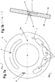
- the exemplary embodiment shows a control plate 1 according to the invention, which is suitable for installation in an axial piston machine between the engine cylinders and the connection plate.
- the main function of the control plate 1 is to supply the engine cylinders of the axial piston pump with hydraulic oil. Due to the geometry and the position of the high pressure kidneys 3 for a given cylinder kidney shape, the control plate 1 defines the angle of rotation ranges to which a respective engine cylinder is connected to the low pressure side of the oil circuit. As a result, the movement of the engine piston (along its longitudinal axis out of the engine cylinder) hydraulic oil can be sucked into the corresponding hydraulic cylinder. When the engine continues to rotate, the respective engine cylinder is also connected to the high pressure side of the oil circuit, whereby the hydraulic oil is pressed into the high pressure oil circuit in the course of the corresponding engine piston movement in the opposite direction.
- Figure 1 shows a top view of side 1a of the control plate 1 according to the invention facing the engine cylinder of an axial piston pump.
- the control plate 1 shown comprises a centrally arranged centering opening 6 as well as a total of four high-pressure kidneys 3 and a larger-sized suction kidney 5, the kidneys all being elongated holes through the control plate 1 are shaped.
- the size of the high pressure kidneys 3 is identical, the dimensions of the suction kidney 5, in contrast, are significantly larger, ie longer.
- the suction kidney 5 extends over the ring area of the control plate 1 opposite the centering opening 6.
- a control notch 2 extends in the first intermediate area, which directly adjoins the end of the outer high pressure kidney 3 and extends in the direction of the suction kidney 5.
- a relief opening 4 is provided in the intermediate area between the high pressure kidney 3 and suction kidney 5 on the other side of the centering opening.
- FIG. 1 A top perspective view of the Figure 1 underlying surface 1b of the control plate 1 is in the Figure 4 reproduced. In the installation position within the axial piston pump, this surface 1b faces the connection plate.
- the high pressure kidneys 3 and the suction kidneys 5 can also be seen in the area of the relief opening on the surface 1a of the control plate 1, the relief notch 8 with the groove-like depression at the end to form a blind hole 9 lies on the underside.
- the blind hole 9 opens into the relief opening 4.
- a cutout 7 is provided in the area of the suction kidney 5 on the outer circumference, which is a recess in the circumference of the control plate 1.
- the cutout 7 fulfills two functions. On the one hand, it represents an assembly aid in that the correct installation position with the correct angle between the control plate and the axial piston pump is enforced by plugging the cutout onto a protruding bolt on the connection plate. On the other hand, a fixation of the control plate is achieved at the same time during pump operation and this is secured against unintentional rotation during operation.
- control plate 1 which is essentially formed from the illustrated control plate 1 without the openings or notches 2-9
- the control plate 1 according to the invention is produced according to FIGS Figures 1 to 5 produced.
- the high pressure kidneys 3 and the suction kidney 5, the centering opening 6 as well as the relief opening 4 and the cutout 7 for fixing the control plate 1 are produced by a combination of pre-embossing and punching.
- the production of the control and relief notches 2, 8, on the other hand, is achieved by simple stamping.
- the embossing makes it possible to form fine control elements that are not possible using machining processes or can only be implemented with considerable effort.
- the production of openings by embossing and then punching through enables shapes that can only be implemented with considerable additional effort using machining processes.
- the embossing included in the manufacturing process i.e. the production of the notches 2, 5 by embossing and the production of openings 3, 5, 6, 7 by pre-embossing with subsequent punching, also leads to material compression on the material surfaces 1 a, newly created by machining the control plate blank 1b of the completed control plate 1.
- the material compression also results in an alignment of the Metal fibers, which, like the material compression itself, result in a higher component strength. In particular, the crack resistance of the control plate 1 increases.
- FIG. 2a shows a detailed view of the control notch 2, which adjoins the edge of a high pressure kidney 3.
- the control notch represents a depression in the surface 1 a of the control plate 1, which continues in the longitudinal direction of the high pressure kidney 3 and is oriented in the direction of the suction kidney 5.
- the free end of the control notch 2 has two side edges 2a, 2b which are at right angles to one another.
- the depth of penetration of the control notch 2 into the control plate 1 can decrease exponentially starting from the high pressure kidney 3 in the direction of the free end, ie the bottom of the control notch can show a concave or convex course.
- the bottom can be straight, as shown on the basis of the sectional view of FIG Figure 2b can be seen along the cutting axis BB, ie the notch 2 shows a constantly decreasing penetration depth.
- the pointed end of the control notch 2 with the side edges 2a, 2b can only be produced by the production method according to the invention (embossing & punching), since the conventional production method using a milling cutter always results in a radius in the end area of the notch.
- the entire surface area 1a, 1b of the control plate 1 must be ground so that the dimensional accuracy and surface quality that can be achieved are sufficient. For this reason, the minimum embossing depth of the control notch 2 must be selected to be at least so deep that the length l of the control notch 2 does not become smaller during the subsequent material removal by the grinding process.
- Figure 3 a detailed view of the high pressure kidney 3 in connection with the control notch 2 is shown again.
- the thickness a corresponds to the original thickness of the control plate 1
- b represents the thickness of the control plate 1 after the grinding process. It can be seen in this context that the minimum depth of the embossing of the control notch 2 extends deeper into the control plate than the material removal achieved by the grinding process. As a result, the length I of the control notch 2 does not change by the grinding process.
- FIGS. 5a, 5b again show detailed views of the underside 1b of the control plate 1 with the relief notch 8 and the relief opening 4.
- the illustration of FIG Figure 5a shows a detailed view of the surface 1b in the area of the relief notch 8. It can be seen here that the end of the notch 8 protrudes deeper into the control plate 1 on the side facing the main groove 3 and thereby forms the blind hole 9.
- the blind hole 9 of the relief notch 8 opens into the relief opening 4 of the surface 1a.
- a sectional view through the relief notch 8 in the area of the blind hole 9 along the section line EE shows Figure 5b .
- the channel formed by the surface 1b accordingly tapers in the direction of the surface 1a.
- the relief notch 8 including the blind hole 9 is embossed. The metal is then pierced by punching in the center of the material hole 9 and the relief opening 4 is created.
- FIG. 6 Another embodiment of a control plate is the Figure 6 refer to.
- the side 10a of the control plate 10 facing the engine cylinder of an axial piston pump is essentially the same as the control plate 1 according to FIG Figure 1 . Identical features are therefore provided with identical reference symbols.
- the only difference between the control plate 10 and the control plate 1 is that the relief opening 4 is provided on the side 10a with an additional notch-like recess 40 (additional relief notch). Starting from the relief opening 4, this recess 40 converges to a point in the direction of the high pressure kidney 3.
- the underside 10b of the control plate 10 corresponds in its design to the underside 1b of the control plate 1 according to FIG Figure 4 .
- the width of the recess 40 at the beginning corresponds to the width of the relief opening and converges to a point in the direction of the high pressure kidney 3.
- This shape of the recess 40 which converges to a point, is only made possible by the production method according to the invention by means of embossing and punching.
- the novel shape in the area of the relief opening 4 shows certain advantages in operation. Cavitation clearly leads to an uncontrolled change in geometry. Damage in the area of the relief opening due to cavitation is significantly reduced due to the depression 40.
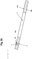
- FIG Figure 8 Another alternative embodiment of the control plate is shown in FIG Figure 8 shown.
- This control plate 100 also differs from the control plate 1, 10 only in the design of the relief opening 4 on the side 100a.
- a rectangular transverse groove 400 is formed around the relief opening 4, which also serves as an additional relief notch 400 on the side 100a.
- the rectangular shape of the additional transverse groove 400 is shown in the plan view Figure 9a as well as in the sectional view according to Figure 9b can be seen along the section axis EE.
- the embossing 400 shown here can of course take place in a precisely defined manner.
- a rectangular shape of the transverse groove 400 can be produced by the embossing process, since this avoids undesired radii at the corner points.
- control plates 1, 10, 100 were limited to the pump operation of the axial piston unit. Such a control plate 1, 10, 100 could of course also be used for engine operation.
Claims (11)
- Procédé de fabrication d'une plaque de commande (1) pour une machine hydraulique, en particulier une machine à pistons axiaux, une ébauche de plaque de commande étant fabriquée en métal puis la géométrie de l'ébauche de plaque de commande étant modifiée par fabrication sans enlèvement de copeaux pour la réalisation des fonctions de commande, la modification comprenant la fabrication d'un ou plusieurs orifices traversants,
caractérisé en ce que
le formage sans enlèvement de copeaux comprend l'étape de travail de l'estampage/pré-estampage en liaison avec un refoulement de matière, les orifices traversant la plaque de commande (1) étant en plus percés par poinçonnage après le pré-estampage. - Procédé selon la revendication 1, caractérisé en ce que la modification comprend la fabrication d'un ou de plusieurs reins (3, 5) et/ou d'un orifice de centrage (6) et/ou d'un ou de plusieurs orifices de décharge (4) et/ou d'une ou de plusieurs encoches (2, 8, 40), par exemple une ou plusieurs encoches de décharge et/ou de commande (2, 8), et/ou d'un ou de plusieurs trous borgnes (9), et/ou au moins d'une découpe de fixation (7) pour la fixation de la plaque de commande (1).
- Procédé selon la revendication 2, caractérisé en ce que la mise en œuvre de la ou des encoches de décharge et/ou de commande (2, 8, 40) et/ou d'au moins un trou borgne (9) est effectuée par estampage et refoulement de matière.
- Procédé selon l'une des revendications précédentes 2 à 3, caractérisé en ce que la mise en œuvre de l'orifice de centrage (6) et/ou d'au moins un rein (3, 5) et/ou d'au moins un orifice de décharge (4) et/ou d'une découpe de fixation (7) est effectuée par pré-estampage et poinçonnage subséquent.
- Procédé selon l'une des revendications précédentes 3 ou 4, caractérisé en ce que l'étape de procédé d'estampage/pré-estampage est effectuée en une étape de travail et un poinçonnage subséquent est effectué de préférence sans nouveau serrage de la pièce directement après l'estampage/pré-estampage.
- Procédé selon l'une des revendications précédentes, caractérisé en ce qu'au moins une surface (1a, 1b) de la plaque de commande (1) est rectifiée après l'estampage/pré-estampage et le poinçonnage.
- Procédé selon la revendication 6, caractérisé en ce que la profondeur d'estampage d'au moins une encoche (2, 8, 40), en particulier de l'encoche de commande (2), est supérieure à l'enlèvement sur la surface (1a, 1b) obtenu par le processus de rectification, de telle sorte que la longueur de l'au moins une encoche (2, 8, 40), en particulier de l'encoche de commande (2), reste constante malgré le processus de rectification.
- Procédé selon l'une des revendications précédentes, caractérisé en ce que la profondeur d'estampage de l'encoche de décharge (8) varie, la zone avec pénétration plus profonde dans l'ébauche de plaque de commande étant définie comme trou borgne (9), un orifice de décharge (4) étant réalisé de préférence par poinçonnage du trou borgne (9).
- Procédé selon l'une des revendications précédentes, caractérisé en ce que des contours et/ou des creux sont fabriqués sans rayon sur la surface de plaque de commande (1a, 1b), une encoche (2, 8, 40) de forme polygonale, par exemple avec une extrémité d'encoche rétrécissant en pointe et/ou une forme d'encoche rectangulaire, étant de préférence fabriquée.
- Plaque de commande (1) pour une machine hydraulique, en particulier une machine à pistons axiaux, qui a été fabriquée par le procédé selon l'une des revendications précédentes, comprenant un ou plusieurs reins à haute pression et/ou d'aspiration (3, 5) ainsi qu'au moins une encoche (2, 8, 40), en particulier une encoche de décharge et/ou de commande (2, 8),
caractérisée en ce que
l'au moins une encoche (2, 8, 40) forme une rainure longitudinale rétrécissant en pointe ou une rainure transversale rectangulaire sur au moins une surface (1a, 1b) de la plaque de commande (1), le contour de l'au moins une encoche (2, 8, 40) ne présentant pas de rayon dans les coins. - Machine à pistons axiaux, en particulier pompe à pistons axiaux ou moteur à pistons axiaux, comprenant au moins une plaque de commande (1) selon la revendication 10.
Applications Claiming Priority (1)
| Application Number | Priority Date | Filing Date | Title |
|---|---|---|---|
| CH01520/15A CH711662A1 (de) | 2015-10-15 | 2015-10-15 | Herstellungsverfahren für Steuerplatten einer hydraulischen Maschine. |
Publications (2)
| Publication Number | Publication Date |
|---|---|
| EP3156643A1 EP3156643A1 (fr) | 2017-04-19 |
| EP3156643B1 true EP3156643B1 (fr) | 2021-03-24 |
Family
ID=57240786
Family Applications (1)
| Application Number | Title | Priority Date | Filing Date |
|---|---|---|---|
| EP16187567.9A Active EP3156643B1 (fr) | 2015-10-15 | 2016-09-07 | Procédé de fabrication de plaques de commande d'une machine hydraulique |
Country Status (2)
| Country | Link |
|---|---|
| EP (1) | EP3156643B1 (fr) |
| CH (1) | CH711662A1 (fr) |
Families Citing this family (1)
| Publication number | Priority date | Publication date | Assignee | Title |
|---|---|---|---|---|
| CN113906212A (zh) * | 2019-06-26 | 2022-01-07 | 丹佛斯动力系统Ii技术有限公司 | 用于流体泵的阀板 |
Citations (5)
| Publication number | Priority date | Publication date | Assignee | Title |
|---|---|---|---|---|
| DE2047557A1 (de) * | 1969-10-06 | 1971-04-22 | VEB Kombinat Orsta Hydraulik Be trieb Industnewerke Karl Marx Stadt, χ 9030 Karl Marx Stadt | Hydrostatische Kolbenmaschine |
| DE3140339A1 (de) * | 1981-10-10 | 1983-04-28 | Goetze Ag, 5093 Burscheid | Steuerscheibe fuer hydromotoren und ihr herstellungsverfahren |
| EP0301310A1 (fr) * | 1987-07-30 | 1989-02-01 | BRUENINGHAUS HYDRAULIK GmbH | Machine à piston axiaux du type à plateaux ou axes inclinés avec des lumières de distribution et des canaux de compensation de pression |
| US6981321B1 (en) * | 2003-09-29 | 2006-01-03 | Sauer-Danfoss Inc. | Hydrostatic cylinder block and method of making the same |
| DE102007008049A1 (de) * | 2007-02-17 | 2008-08-21 | Thyssenkrupp Vdm Gmbh | Gleitender Reibung ausgesetztes Bauteil |
Family Cites Families (8)
| Publication number | Priority date | Publication date | Assignee | Title |
|---|---|---|---|---|
| FR956823A (fr) * | 1944-10-30 | 1950-02-08 | ||
| US4550645A (en) * | 1984-04-27 | 1985-11-05 | Sundstrand Corporation | Thin valve plate for a hydraulic unit |
| JPH11182410A (ja) * | 1997-12-24 | 1999-07-06 | Nachi Fujikoshi Corp | 多連ピストンポンプ及びバルブプレート及びその製造方法 |
| US6196109B1 (en) * | 1998-11-16 | 2001-03-06 | Eaton Corporation | Axial piston pump and improved valve plate design therefor |
| IT1319854B1 (it) * | 2000-02-22 | 2003-11-03 | Embraco Europ Srl | Procedimento per la fabbricazione di una piastra valvolare dicompressore, piastra valvolare ottenuta con il procedimento, gruppo |
| DE10200545A1 (de) * | 2001-12-11 | 2003-06-26 | Liebherr Machines Bulle S A | Steuerplatte für Hydromotoren und -pumpen vom Axialkolbentyp sowie Verfahren zu ihrer Herstellung |
| DE10251552C5 (de) * | 2002-11-05 | 2010-07-15 | Brueninghaus Hydromatik Gmbh | Axialkolbenmaschine und Steuerplatte für eine Axialkolbenmaschine |
| JP5478577B2 (ja) * | 2011-09-27 | 2014-04-23 | 株式会社豊田自動織機 | 圧縮機 |
-
2015
- 2015-10-15 CH CH01520/15A patent/CH711662A1/de not_active Application Discontinuation
-
2016
- 2016-09-07 EP EP16187567.9A patent/EP3156643B1/fr active Active
Patent Citations (5)
| Publication number | Priority date | Publication date | Assignee | Title |
|---|---|---|---|---|
| DE2047557A1 (de) * | 1969-10-06 | 1971-04-22 | VEB Kombinat Orsta Hydraulik Be trieb Industnewerke Karl Marx Stadt, χ 9030 Karl Marx Stadt | Hydrostatische Kolbenmaschine |
| DE3140339A1 (de) * | 1981-10-10 | 1983-04-28 | Goetze Ag, 5093 Burscheid | Steuerscheibe fuer hydromotoren und ihr herstellungsverfahren |
| EP0301310A1 (fr) * | 1987-07-30 | 1989-02-01 | BRUENINGHAUS HYDRAULIK GmbH | Machine à piston axiaux du type à plateaux ou axes inclinés avec des lumières de distribution et des canaux de compensation de pression |
| US6981321B1 (en) * | 2003-09-29 | 2006-01-03 | Sauer-Danfoss Inc. | Hydrostatic cylinder block and method of making the same |
| DE102007008049A1 (de) * | 2007-02-17 | 2008-08-21 | Thyssenkrupp Vdm Gmbh | Gleitender Reibung ausgesetztes Bauteil |
Also Published As
| Publication number | Publication date |
|---|---|
| CH711662A1 (de) | 2017-04-28 |
| EP3156643A1 (fr) | 2017-04-19 |
Similar Documents
| Publication | Publication Date | Title |
|---|---|---|
| DE60019929T2 (de) | Bohrer mit drei schneidkanten | |
| DE102017123786A1 (de) | Halter für ein Nutstoßwerkzeug | |
| DE102012016660A1 (de) | Einlippenbohrer | |
| EP2091681B2 (fr) | Plaquette de coupe pour un outil de tournage et procédé d'usinage avec cette plaquette de coupe | |
| DE102007024174B4 (de) | Axialkolbenmaschine mit einer Verdrehsicherung für die Steuerplatte | |
| WO2007096336A1 (fr) | Dispositif et procede de réalisation d'une decoupe en forme de calotte dans une piece par enlevement de matiere | |
| DE10300070A1 (de) | Axialkolbenmaschine, Rückzugplatte und Verfahren zum Herstellen einer Rückzugplatte | |
| EP3156643B1 (fr) | Procédé de fabrication de plaques de commande d'une machine hydraulique | |
| DE10251552C5 (de) | Axialkolbenmaschine und Steuerplatte für eine Axialkolbenmaschine | |
| DE102006015367B4 (de) | Drehantreibbares Werkzeug zur Herstellung von Gewinden | |
| EP3501767A1 (fr) | Dispositif et procédé de changement | |
| EP3085492B1 (fr) | Outil de rectification | |
| DE102015206716A1 (de) | Schrägscheibenmaschine | |
| EP3797911B1 (fr) | Fraise à queue et son procédé de fabrication | |
| EP2976174B1 (fr) | Élément d'alésage et alésoir et sa méthode de production | |
| DE102009040510A1 (de) | Rotor für eine Pumpe | |
| DE102008056782A1 (de) | Entgratreibahle | |
| DE102008049515B4 (de) | Verfahren zur spanenden Bearbeitung von Werkstückflächen an Werkstücken, insbesondere an Kurbelwellen, sowie Schneidplatte zur Durchführung eines solchen Verfahrens | |
| EP3284558A1 (fr) | Procédé d'usinage d'un piston | |
| EP4241948A1 (fr) | Agrégat pour l'usinage d'une surface de chant d'un panneau en matériau dérivé du bois et procédé d'usinage | |
| WO2020207937A1 (fr) | Compresseur à pistons alternatifs | |
| DE102008049516B4 (de) | Verfahren zur spanenden Bearbeitung von Werkstückflächen an Werkstücken, insbesondere an Kurbelwellen, sowie Schneideinsatz zur Durchführung eines solchen Verfahrens | |
| WO2009109283A1 (fr) | Carter de moteur oscillant | |
| EP1900452A1 (fr) | Procédé de renforcement d'un paroi d'une garniture tridimensionnelle | |
| EP1561031A1 (fr) | Moteur a pistons axiaux, plateau oscillant et procede de fabrication d'un plateau oscillant |
Legal Events
| Date | Code | Title | Description |
|---|---|---|---|
| PUAI | Public reference made under article 153(3) epc to a published international application that has entered the european phase |
Free format text: ORIGINAL CODE: 0009012 |
|
| STAA | Information on the status of an ep patent application or granted ep patent |
Free format text: STATUS: THE APPLICATION HAS BEEN PUBLISHED |
|
| AK | Designated contracting states |
Kind code of ref document: A1 Designated state(s): AL AT BE BG CH CY CZ DE DK EE ES FI FR GB GR HR HU IE IS IT LI LT LU LV MC MK MT NL NO PL PT RO RS SE SI SK SM TR |
|
| AX | Request for extension of the european patent |
Extension state: BA ME |
|
| STAA | Information on the status of an ep patent application or granted ep patent |
Free format text: STATUS: REQUEST FOR EXAMINATION WAS MADE |
|
| 17P | Request for examination filed |
Effective date: 20171016 |
|
| STAA | Information on the status of an ep patent application or granted ep patent |
Free format text: STATUS: EXAMINATION IS IN PROGRESS |
|
| 17Q | First examination report despatched |
Effective date: 20190808 |
|
| REG | Reference to a national code |
Ref country code: DE Ref legal event code: R079 Ref document number: 502016012646 Country of ref document: DE Free format text: PREVIOUS MAIN CLASS: F03C0001340000 Ipc: F03C0001060000 |
|
| GRAP | Despatch of communication of intention to grant a patent |
Free format text: ORIGINAL CODE: EPIDOSNIGR1 |
|
| STAA | Information on the status of an ep patent application or granted ep patent |
Free format text: STATUS: GRANT OF PATENT IS INTENDED |
|
| RIC1 | Information provided on ipc code assigned before grant |
Ipc: F03C 1/06 20060101AFI20200925BHEP Ipc: F04B 1/20 20200101ALI20200925BHEP |
|
| INTG | Intention to grant announced |
Effective date: 20201019 |
|
| GRAS | Grant fee paid |
Free format text: ORIGINAL CODE: EPIDOSNIGR3 |
|
| GRAA | (expected) grant |
Free format text: ORIGINAL CODE: 0009210 |
|
| STAA | Information on the status of an ep patent application or granted ep patent |
Free format text: STATUS: THE PATENT HAS BEEN GRANTED |
|
| RAP1 | Party data changed (applicant data changed or rights of an application transferred) |
Owner name: LIEBHERR MACHINES BULLE SA |
|
| AK | Designated contracting states |
Kind code of ref document: B1 Designated state(s): AL AT BE BG CH CY CZ DE DK EE ES FI FR GB GR HR HU IE IS IT LI LT LU LV MC MK MT NL NO PL PT RO RS SE SI SK SM TR |
|
| REG | Reference to a national code |
Ref country code: GB Ref legal event code: FG4D Free format text: NOT ENGLISH |
|
| REG | Reference to a national code |
Ref country code: CH Ref legal event code: EP |
|
| REG | Reference to a national code |
Ref country code: DE Ref legal event code: R096 Ref document number: 502016012646 Country of ref document: DE |
|
| REG | Reference to a national code |
Ref country code: IE Ref legal event code: FG4D Free format text: LANGUAGE OF EP DOCUMENT: GERMAN |
|
| REG | Reference to a national code |
Ref country code: AT Ref legal event code: REF Ref document number: 1374736 Country of ref document: AT Kind code of ref document: T Effective date: 20210415 |
|
| REG | Reference to a national code |
Ref country code: LT Ref legal event code: MG9D |
|
| PG25 | Lapsed in a contracting state [announced via postgrant information from national office to epo] |
Ref country code: BG Free format text: LAPSE BECAUSE OF FAILURE TO SUBMIT A TRANSLATION OF THE DESCRIPTION OR TO PAY THE FEE WITHIN THE PRESCRIBED TIME-LIMIT Effective date: 20210624 Ref country code: FI Free format text: LAPSE BECAUSE OF FAILURE TO SUBMIT A TRANSLATION OF THE DESCRIPTION OR TO PAY THE FEE WITHIN THE PRESCRIBED TIME-LIMIT Effective date: 20210324 Ref country code: GR Free format text: LAPSE BECAUSE OF FAILURE TO SUBMIT A TRANSLATION OF THE DESCRIPTION OR TO PAY THE FEE WITHIN THE PRESCRIBED TIME-LIMIT Effective date: 20210625 Ref country code: HR Free format text: LAPSE BECAUSE OF FAILURE TO SUBMIT A TRANSLATION OF THE DESCRIPTION OR TO PAY THE FEE WITHIN THE PRESCRIBED TIME-LIMIT Effective date: 20210324 Ref country code: NO Free format text: LAPSE BECAUSE OF FAILURE TO SUBMIT A TRANSLATION OF THE DESCRIPTION OR TO PAY THE FEE WITHIN THE PRESCRIBED TIME-LIMIT Effective date: 20210624 |
|
| PG25 | Lapsed in a contracting state [announced via postgrant information from national office to epo] |
Ref country code: RS Free format text: LAPSE BECAUSE OF FAILURE TO SUBMIT A TRANSLATION OF THE DESCRIPTION OR TO PAY THE FEE WITHIN THE PRESCRIBED TIME-LIMIT Effective date: 20210324 Ref country code: LV Free format text: LAPSE BECAUSE OF FAILURE TO SUBMIT A TRANSLATION OF THE DESCRIPTION OR TO PAY THE FEE WITHIN THE PRESCRIBED TIME-LIMIT Effective date: 20210324 Ref country code: SE Free format text: LAPSE BECAUSE OF FAILURE TO SUBMIT A TRANSLATION OF THE DESCRIPTION OR TO PAY THE FEE WITHIN THE PRESCRIBED TIME-LIMIT Effective date: 20210324 |
|
| REG | Reference to a national code |
Ref country code: NL Ref legal event code: MP Effective date: 20210324 |
|
| PG25 | Lapsed in a contracting state [announced via postgrant information from national office to epo] |
Ref country code: NL Free format text: LAPSE BECAUSE OF FAILURE TO SUBMIT A TRANSLATION OF THE DESCRIPTION OR TO PAY THE FEE WITHIN THE PRESCRIBED TIME-LIMIT Effective date: 20210324 |
|
| PG25 | Lapsed in a contracting state [announced via postgrant information from national office to epo] |
Ref country code: SM Free format text: LAPSE BECAUSE OF FAILURE TO SUBMIT A TRANSLATION OF THE DESCRIPTION OR TO PAY THE FEE WITHIN THE PRESCRIBED TIME-LIMIT Effective date: 20210324 Ref country code: EE Free format text: LAPSE BECAUSE OF FAILURE TO SUBMIT A TRANSLATION OF THE DESCRIPTION OR TO PAY THE FEE WITHIN THE PRESCRIBED TIME-LIMIT Effective date: 20210324 Ref country code: CZ Free format text: LAPSE BECAUSE OF FAILURE TO SUBMIT A TRANSLATION OF THE DESCRIPTION OR TO PAY THE FEE WITHIN THE PRESCRIBED TIME-LIMIT Effective date: 20210324 Ref country code: LT Free format text: LAPSE BECAUSE OF FAILURE TO SUBMIT A TRANSLATION OF THE DESCRIPTION OR TO PAY THE FEE WITHIN THE PRESCRIBED TIME-LIMIT Effective date: 20210324 |
|
| PG25 | Lapsed in a contracting state [announced via postgrant information from national office to epo] |
Ref country code: ES Free format text: LAPSE BECAUSE OF FAILURE TO SUBMIT A TRANSLATION OF THE DESCRIPTION OR TO PAY THE FEE WITHIN THE PRESCRIBED TIME-LIMIT Effective date: 20210324 Ref country code: PL Free format text: LAPSE BECAUSE OF FAILURE TO SUBMIT A TRANSLATION OF THE DESCRIPTION OR TO PAY THE FEE WITHIN THE PRESCRIBED TIME-LIMIT Effective date: 20210324 Ref country code: PT Free format text: LAPSE BECAUSE OF FAILURE TO SUBMIT A TRANSLATION OF THE DESCRIPTION OR TO PAY THE FEE WITHIN THE PRESCRIBED TIME-LIMIT Effective date: 20210726 Ref country code: SK Free format text: LAPSE BECAUSE OF FAILURE TO SUBMIT A TRANSLATION OF THE DESCRIPTION OR TO PAY THE FEE WITHIN THE PRESCRIBED TIME-LIMIT Effective date: 20210324 Ref country code: RO Free format text: LAPSE BECAUSE OF FAILURE TO SUBMIT A TRANSLATION OF THE DESCRIPTION OR TO PAY THE FEE WITHIN THE PRESCRIBED TIME-LIMIT Effective date: 20210324 Ref country code: IS Free format text: LAPSE BECAUSE OF FAILURE TO SUBMIT A TRANSLATION OF THE DESCRIPTION OR TO PAY THE FEE WITHIN THE PRESCRIBED TIME-LIMIT Effective date: 20210724 |
|
| REG | Reference to a national code |
Ref country code: DE Ref legal event code: R097 Ref document number: 502016012646 Country of ref document: DE |
|
| PG25 | Lapsed in a contracting state [announced via postgrant information from national office to epo] |
Ref country code: DK Free format text: LAPSE BECAUSE OF FAILURE TO SUBMIT A TRANSLATION OF THE DESCRIPTION OR TO PAY THE FEE WITHIN THE PRESCRIBED TIME-LIMIT Effective date: 20210324 Ref country code: AL Free format text: LAPSE BECAUSE OF FAILURE TO SUBMIT A TRANSLATION OF THE DESCRIPTION OR TO PAY THE FEE WITHIN THE PRESCRIBED TIME-LIMIT Effective date: 20210324 |
|
| PLBE | No opposition filed within time limit |
Free format text: ORIGINAL CODE: 0009261 |
|
| STAA | Information on the status of an ep patent application or granted ep patent |
Free format text: STATUS: NO OPPOSITION FILED WITHIN TIME LIMIT |
|
| PG25 | Lapsed in a contracting state [announced via postgrant information from national office to epo] |
Ref country code: SI Free format text: LAPSE BECAUSE OF FAILURE TO SUBMIT A TRANSLATION OF THE DESCRIPTION OR TO PAY THE FEE WITHIN THE PRESCRIBED TIME-LIMIT Effective date: 20210324 |
|
| 26N | No opposition filed |
Effective date: 20220104 |
|
| REG | Reference to a national code |
Ref country code: CH Ref legal event code: PL |
|
| REG | Reference to a national code |
Ref country code: BE Ref legal event code: MM Effective date: 20210930 |
|
| GBPC | Gb: european patent ceased through non-payment of renewal fee |
Effective date: 20210907 |
|
| PG25 | Lapsed in a contracting state [announced via postgrant information from national office to epo] |
Ref country code: IS Free format text: LAPSE BECAUSE OF FAILURE TO SUBMIT A TRANSLATION OF THE DESCRIPTION OR TO PAY THE FEE WITHIN THE PRESCRIBED TIME-LIMIT Effective date: 20210724 Ref country code: MC Free format text: LAPSE BECAUSE OF FAILURE TO SUBMIT A TRANSLATION OF THE DESCRIPTION OR TO PAY THE FEE WITHIN THE PRESCRIBED TIME-LIMIT Effective date: 20210324 |
|
| PG25 | Lapsed in a contracting state [announced via postgrant information from national office to epo] |
Ref country code: LU Free format text: LAPSE BECAUSE OF NON-PAYMENT OF DUE FEES Effective date: 20210907 Ref country code: IE Free format text: LAPSE BECAUSE OF NON-PAYMENT OF DUE FEES Effective date: 20210907 Ref country code: GB Free format text: LAPSE BECAUSE OF NON-PAYMENT OF DUE FEES Effective date: 20210907 Ref country code: FR Free format text: LAPSE BECAUSE OF NON-PAYMENT OF DUE FEES Effective date: 20210930 Ref country code: BE Free format text: LAPSE BECAUSE OF NON-PAYMENT OF DUE FEES Effective date: 20210930 |
|
| PG25 | Lapsed in a contracting state [announced via postgrant information from national office to epo] |
Ref country code: LI Free format text: LAPSE BECAUSE OF NON-PAYMENT OF DUE FEES Effective date: 20210930 Ref country code: CH Free format text: LAPSE BECAUSE OF NON-PAYMENT OF DUE FEES Effective date: 20210930 |
|
| REG | Reference to a national code |
Ref country code: AT Ref legal event code: MM01 Ref document number: 1374736 Country of ref document: AT Kind code of ref document: T Effective date: 20210907 |
|
| PG25 | Lapsed in a contracting state [announced via postgrant information from national office to epo] |
Ref country code: IT Free format text: LAPSE BECAUSE OF FAILURE TO SUBMIT A TRANSLATION OF THE DESCRIPTION OR TO PAY THE FEE WITHIN THE PRESCRIBED TIME-LIMIT Effective date: 20210324 Ref country code: AT Free format text: LAPSE BECAUSE OF NON-PAYMENT OF DUE FEES Effective date: 20210907 |
|
| PG25 | Lapsed in a contracting state [announced via postgrant information from national office to epo] |
Ref country code: HU Free format text: LAPSE BECAUSE OF FAILURE TO SUBMIT A TRANSLATION OF THE DESCRIPTION OR TO PAY THE FEE WITHIN THE PRESCRIBED TIME-LIMIT; INVALID AB INITIO Effective date: 20160907 |
|
| PG25 | Lapsed in a contracting state [announced via postgrant information from national office to epo] |
Ref country code: CY Free format text: LAPSE BECAUSE OF FAILURE TO SUBMIT A TRANSLATION OF THE DESCRIPTION OR TO PAY THE FEE WITHIN THE PRESCRIBED TIME-LIMIT Effective date: 20210324 |
|
| PGFP | Annual fee paid to national office [announced via postgrant information from national office to epo] |
Ref country code: DE Payment date: 20230928 Year of fee payment: 8 |