EP3156313A1 - Handlebar fastener for a switchgear unit - Google Patents
Handlebar fastener for a switchgear unit Download PDFInfo
- Publication number
- EP3156313A1 EP3156313A1 EP16193394.0A EP16193394A EP3156313A1 EP 3156313 A1 EP3156313 A1 EP 3156313A1 EP 16193394 A EP16193394 A EP 16193394A EP 3156313 A1 EP3156313 A1 EP 3156313A1
- Authority
- EP
- European Patent Office
- Prior art keywords
- handlebar
- adapter
- switching unit
- receiving
- adapter device
- Prior art date
- Legal status (The legal status is an assumption and is not a legal conclusion. Google has not performed a legal analysis and makes no representation as to the accuracy of the status listed.)
- Granted
Links
- 230000001419 dependent effect Effects 0.000 description 2
- 238000005553 drilling Methods 0.000 description 1
- 230000005484 gravity Effects 0.000 description 1
- 239000002655 kraft paper Substances 0.000 description 1
- 238000004519 manufacturing process Methods 0.000 description 1
Images


Classifications
-
- B—PERFORMING OPERATIONS; TRANSPORTING
- B62—LAND VEHICLES FOR TRAVELLING OTHERWISE THAN ON RAILS
- B62K—CYCLES; CYCLE FRAMES; CYCLE STEERING DEVICES; RIDER-OPERATED TERMINAL CONTROLS SPECIALLY ADAPTED FOR CYCLES; CYCLE AXLE SUSPENSIONS; CYCLE SIDE-CARS, FORECARS, OR THE LIKE
- B62K23/00—Rider-operated controls specially adapted for cycles, i.e. means for initiating control operations, e.g. levers, grips
- B62K23/02—Rider-operated controls specially adapted for cycles, i.e. means for initiating control operations, e.g. levers, grips hand actuated
- B62K23/06—Levers
-
- B—PERFORMING OPERATIONS; TRANSPORTING
- B62—LAND VEHICLES FOR TRAVELLING OTHERWISE THAN ON RAILS
- B62L—BRAKES SPECIALLY ADAPTED FOR CYCLES
- B62L3/00—Brake-actuating mechanisms; Arrangements thereof
- B62L3/02—Brake-actuating mechanisms; Arrangements thereof for control by a hand lever
-
- B—PERFORMING OPERATIONS; TRANSPORTING
- B62—LAND VEHICLES FOR TRAVELLING OTHERWISE THAN ON RAILS
- B62L—BRAKES SPECIALLY ADAPTED FOR CYCLES
- B62L3/00—Brake-actuating mechanisms; Arrangements thereof
- B62L3/02—Brake-actuating mechanisms; Arrangements thereof for control by a hand lever
- B62L3/023—Brake-actuating mechanisms; Arrangements thereof for control by a hand lever acting on fluid pressure systems
-
- B—PERFORMING OPERATIONS; TRANSPORTING
- B62—LAND VEHICLES FOR TRAVELLING OTHERWISE THAN ON RAILS
- B62M—RIDER PROPULSION OF WHEELED VEHICLES OR SLEDGES; POWERED PROPULSION OF SLEDGES OR SINGLE-TRACK CYCLES; TRANSMISSIONS SPECIALLY ADAPTED FOR SUCH VEHICLES
- B62M25/00—Actuators for gearing speed-change mechanisms specially adapted for cycles
- B62M25/02—Actuators for gearing speed-change mechanisms specially adapted for cycles with mechanical transmitting systems, e.g. cables, levers
- B62M25/04—Actuators for gearing speed-change mechanisms specially adapted for cycles with mechanical transmitting systems, e.g. cables, levers hand actuated
-
- B—PERFORMING OPERATIONS; TRANSPORTING
- B62—LAND VEHICLES FOR TRAVELLING OTHERWISE THAN ON RAILS
- B62K—CYCLES; CYCLE FRAMES; CYCLE STEERING DEVICES; RIDER-OPERATED TERMINAL CONTROLS SPECIALLY ADAPTED FOR CYCLES; CYCLE AXLE SUSPENSIONS; CYCLE SIDE-CARS, FORECARS, OR THE LIKE
- B62K21/00—Steering devices
- B62K21/12—Handlebars; Handlebar stems
Definitions
- the invention relates to a handlebar attachment for a switching unit with an adapter device for receiving the switching unit and a fastening device for fastening the adapter device to the handlebar of a handlebar-guided vehicle or bicycle.
- handlebar attachments are known with which switching units are attached to the handlebar tube of a handlebar-guided vehicle or bicycle.
- These handlebar mountings have two half-shells which enclose the handlebar tube together and bolted together for attachment to the handlebar tube with bolts.
- the switching unit has two levers, with which the gears of the gearshift can be switched.
- a cable is pulled and upon actuation of the other lever of the switching unit, the cable is released.
- the levers are arranged below the handlebar tube.
- torque is applied to the handlebar attachment, particularly upon actuation of the lever, the actuation of which causes the cable to be pulled.
- the gear is changed when driving, there is a risk that the handlebar attachment as a result of frequent torque changes triggers. Therefore, the known handlebar mountings must be relatively stable and heavy, so that the handlebar attachment does not solve so easily or the handlebar attachment moves around the handlebar.
- the invention is therefore an object of the invention to provide a handlebar attachment for attaching a switching unit to a handlebar tube, in which the risk is reduced that solves the handlebar attachment to the handlebar tube due to frequent switching.
- a handlebar attachment for a switching unit is provided with an adapter device for receiving the switching unit and a fastening device for fastening the adapter device to the handlebar tube of a handlebar-guided vehicle, wherein the adapter device has a Drehmomentabstütz issued.
- the inventive embodiment of the handlebar attachment has the advantage that a force exerted on the handlebar attachment during actuation of the switching unit torque can be derived directly on the handlebar tube via the Drehmomenabstütz issued the adapter device, so that the fastening device will not turn on the handlebar, because if at all a small torque acts on the frictional connection between the fastening device and the handlebar tube.
- the fastening device may be a clamp whose inner contour preferably corresponds to the outer contour of the handlebar tube.
- the fastening device together with a Geberarmartur include the handlebar tube.
- the fastening device or clamp may be formed as a half-shell.
- the Drehmomentabstütz accordingly be arranged and designed so that it is supported eccentrically on the handlebar tube when the adapter device is fastened with the fastening device on the handlebar tube.
- off-center is meant a region whose center of gravity or which lies substantially or completely below a plane passing through the center of the handlebar tube and parallel to the direction of the force exerted on the switching unit when switching.
- the Drehmonentab spainides may have a rib or a plurality of ribs whose contours correspond in a certain angular range of the outer contour of the handlebar tube.
- the angular range may be at least 30 degrees, preferably at least 45 degrees, more preferably at least 60 degrees, and preferably about 70 degrees or 90 degrees.
- the Drehmonentab spainides may have a rib or a plurality of ribs whose contours correspond in a certain angular range of the outer contour of the handlebar tube.
- the angle range may be less than 180 degrees, preferably less than 150 degrees, more preferably less than 120 degrees, and preferably about 90 degrees or 70 degrees.
- opposite side it is meant a region that is located on the side of the handlebar tube, which is opposite to the side on which the adapter device to., Based on a plane through the center of the handlebar tube, which is parallel to the force exerted on the switching unit when switching Recording the switching unit is arranged.
- the second Drehmonentabstütz Scheme have a rib or a plurality of ribs whose contours correspond in a certain angular range of the outer contour of the handlebar tube.
- the angular range may be at least 30 degrees, preferably at least 45 degrees, more preferably at least 60 degrees, and preferably about 90 degrees.
- the Drehmonentab siniques have two ribs between which an engagement hole for a bolt for attaching the switching unit may be provided on the adapter device.
- the fastening device may have an adapter receiving device for receiving the adapter device.
- various adapter devices can be arranged on the fastening device in order to adapt the handlebar attachment to different switching units.
- This has the advantage that multiple handlebar attachments can be made cheaper. It is also an object of the invention to be able to adapt handlebar attachments for receiving switching units quickly and cost-effectively to new switching units.
- a handlebar attachment for a switching unit with an adapter device for receiving the switching unit and a fastening device for fastening the adapter device to the handlebar of a handlebar-guided vehicle is specified, wherein the fastening device has an adapter receiving device for receiving the adapter device.
- This embodiment has the advantage that due to the modular design, only the adapter device must be adapted to new switching units, whereby design and manufacturing costs can be saved. Also repair costs can be lower, because not the entire handlebar attachment must be replaced.
- the adapter device can be rotatably mounted in the adapter receiving device. This has the advantage that the torque generated during the actuation of the switching unit can be better dissipated to the Drehmomentabstütz adopted and thus directly to the handlebar tube.
- the adapter device can be rotatably mounted in the adapter receiving device about an axis which extends substantially parallel to the axis of the handlebar tube.
- the adapter device can have a switching unit receiving device for receiving the switching unit.
- the adapter device can be fastened to the switching unit with a bolt or a threaded pin.
- the adapter device can have an adjusting device for adjusting the angle in which the switching unit is received by the adapter device.
- the adapter device can have an adjusting device with a detent for receiving the switching unit receiving device of the adapter device and a switching unit receiving device for receiving the switching unit.
- the adapter device can have an adjusting device for adjusting the angle in which the adapter device is received by the fastening device.
- the adjusting device may comprise a spring device and a bolt, which are received in a corresponding opening or bore provided in the adapter device.
- a plurality of bores can be provided around the bolt receptacle, with which different angles between the adapter device and the fastening device can be adjusted.
- a master cylinder for a hydraulic brake with a handlebar attachment is specified, which is formed according to the invention.
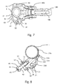
- FIGS. 1 to 7 show a handlebar attachment according to an embodiment of the invention.
- the handlebar attachment has a fastening device 10 with a handlebar tube holder 11.
- the handlebar tube receiving is designed as a clamp or half shell, whose inner contour corresponds to the outer contour of the handlebar tube.
- bolt receptacles 12, 13 and openings are provided on both sides.
- the fastening device 10 is designed such that it encloses the handlebar together with a further fastening device and can be attached thereto.
- the further fastening device may be a simple clamp, so that a separate attachment to the handlebar tube can take place.
- the further fastening device 130 is part of a master cylinder 100 of a hydraulic bicycle brake.
- the further fastening device can also be part of another transducer device, for example hydraulic clutch actuation or a mechanical brake actuation device.
- the hydraulic master cylinder 100 has a lever 110, a housing 120 and a hydraulic line 140.
- a hydraulic transducer device is arranged, which is formed in the manner known in the art.
- the fastening device 130 is arranged, which comprises a half-shell, whose inner contour corresponds to the outer contour of the handlebar tube.
- fastening bolts 61, 62 are inserted through the bolt receptacles and arranged in correspondingly formed receptacles in the mounting device 130 of the master cylinder 100 and fixed there in a known manner, for example via a screw-threaded connection, a press fit etc .
- the fastening device 130 of the master cylinder 100 can also have stud bolts which can be inserted through the bolt receivers 12, 13 of the fastening device 10 and secured in a suitable manner.
- the handlebar attachment has an adapter device 20 and an adapter receiving device 30.
- a switching unit receiving device 24 is formed, which is adapted to a corresponding receptacle of the switching unit.
- the switching unit is used to actuate the gearshift and is constructed in a manner known to those skilled in the art. Usually the switching unit has two levers, with which a cable can be stretched or released, so that the gear shift can be switched in a known manner.
- the adapter receiving device 30 has a fork-like receptacle in which the adapter device 20 is accommodated.
- the fork-shaped receptacle has a fork bottom 31 and two fork legs 32, 33, between which the adapter device 20 is arranged.
- the adapter device 20 is rotatably mounted, namely rotatable about a pin 39 which is arranged in the fork legs 32, 33.
- the adapter device 20 comprises a bolt receiving device 21, in which a bolt receptacle 23 is provided in the form of a passage opening.
- a bolt receiving device 21 in which a bolt receptacle 23 is provided in the form of a passage opening.
- Other embodiments known to those skilled in the art for the rotatable arrangement of the adapter device 20 in the fastening device 10 are conceivable.
- the adapter device 20 At its end opposite the bolt receiving device 21, the adapter device 20 has a shift unit receiving device 24, to which the shift unit can be attached.
- the adapter device 20 has a Drehmomentabstütz Road 22, with which the adapter device 20 is supported on the handlebar tube 1. This has the advantage that in the operation of the switching unit, not shown in the drawings in the adapter device 20 introduced forces are not directed to the fastening device 10, but directly to the handlebar tube 1, so that no torque is exerted on the fastening device 10.
- the torque support device 22 extends over an angular range of approximately 90 degrees.
- the angular range of the Drehmomentabsteitinoplasty 22 is substantially or completely below the plane 2, which extends through the center of the handlebar tube 1 and parallel to the direction of the force when switching to the (not shown) usually two levers for upshifting and downshifting having switching unit is exercised.
- the switching unit is designed so that it can be fastened with a bolt 40 directly to the switching unit receiving device 24.
- the bolt 40 has a bolt head 41 with a tool engagement 43 and a bolt shank 42.
- the bolt is inserted with its bolt shank 42 through a corresponding opening of the switching unit and held there with its bolt head 41.
- the bolt shaft 42 is secured in the switching unit receiving means 24, for example, in a threaded hole provided there.
- an adjusting device 50 is provided on the switching unit receiving means 24, which is provided between the switching unit receiving means 24 of the adapter means 20 and the switching unit.
- the adjusting device 50 has a dial 52 with a detent 51.
- the detent 51 is engaged with the switching unit receiving means 24 having a substantially square cross section.
- a switching unit receiving means 53 is provided which corresponds to the switching unit receiving means 24.
- the switching unit receiving means 53 can be rotated relative to the switching unit receiving means 24, in predetermined by the detent 51 angular increments.
- the detent 51 angular increments.
- 12 positions possible by the detent which corresponds to angular steps of 30 degrees.
- a frictional engagement for example in the form of Reib lake be provided to the detent 51 and to provide a finer adjustment.
- the inclusion of the adapter device 20 in the fastening device 10 has the further advantage that in the fastening device 10 different adapter device 20 can be added, which are adapted to switching units with different shots. As a result, costs can be saved because only smaller parts and not the entire fastening device can be adjusted.
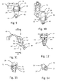
- FIG. 8 shows a further embodiment of a handlebar attachment according to the invention.
- This embodiment essentially corresponds to that in the FIGS. 1 to 7 shown embodiment, so that reference is made to their description, and only the differences will be described below.
- Corresponding or identical parts are described with the same reference numerals and terms, which are optionally additionally provided with the letter A.
- FIG. 8 shown embodiment on another Drehmomentabstütz Scheme 27A. This is related to the plane in which the force exerted on the switching unit when shifting gears arranged on the rear or opposite side of the handlebar tube 1, so that the forces in the opposite direction on the handlebar can be supported.
- the second Drehmonentabstweil Scheme 27A has a rib which extends between the fork bottom 31A and the handlebar tube 1 to behind the handlebar tube and through a passage 35A in the fork bottom 31A.
- the second Drehmeomenabstweil Scheme extends over about 90 degrees. Since the torque-assisting device also extends over about 90 degrees, the handlebar tube is enclosed by more than 180 degrees of torque-supporting portions.
- FIGS. 9 to 14 show a further embodiment of a handlebar attachment according to the invention.
- This embodiment essentially corresponds to that in the FIGS. 1 to 7 shown embodiment, so that reference is made to their description, and only the differences will be described below. Corresponding or identical parts are described with the same reference numerals and terms that are possibly provided with a dash.
- an adjusting device 70 with which the angle between the adapter device 20 'and the fastening device 10 can be adjusted.
- the adjusting device 70 has a spring device 71 and a bolt 72, which are received in a corresponding opening or bore 25 ', which is provided in the adapter device 20'.
- a corresponding opening 34' is provided, into which the end 73 of the bolt 72 engages.
- FIGS. 15 to 20 show a further embodiment of a handlebar attachment according to the invention.
- This embodiment essentially corresponds to that in the FIGS. 1 to 7 shown embodiment, so that reference is made to their description, and only the differences will be described below.
- Corresponding or identical parts are described with the same reference numerals and terms that are optionally provided with two lines.
- FIGS. 15 to 20 An alternative adapter device 20 "is provided, which is adapted to another switching unit.
- the switching unit receiving device 24" is narrower and longer than the switching unit receiving device 24 of the embodiment of FIGS. 1 to 7 ,
- the switching unit can only be attached directly to the switching unit receiving means 24 "at a certain predetermined angle with the bolt FIGS. 14 to 19 embodiment shown also a corresponding to the execution of FIGS. 1 to 7 trained adjusting device 50 may have, the switching unit receiving means then according to the switching unit receiving means 24 "should be formed.
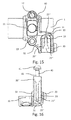
- FIGS. 21 to 24 show a further embodiment of a handlebar attachment according to the invention.
- This embodiment essentially corresponds to that in the FIGS. 1 to 7 shown embodiment, so that reference is made to their description, and only the differences will be described below.
- Corresponding or identical parts are described with the same reference numerals and terms, which are optionally provided with three dashes.
- the bolt 40B is arranged such that the bolt shank 42B is arranged in the direction of the switching unit and can be screwed into a threaded hole provided in the switching unit in order to fasten the shifting unit to the adapter device 20 " be arranged and fastened with the bolt.
- an engagement hole 26B is provided in the adapter device 20, through which the tool engagement 43B of the bolt head 41B can be achieved to fix the shift unit to the adapter device 20. Therefore, the torque arm 22B has two ribs respectively disposed laterally of the engaging hole 26B and substantially similar to the rib of FIGS. 1 to 7 is shown embodiment, however, which is provided in the middle of the adapter device.
Abstract
Die Erfindung betrifft eine Lenkerbefestigung für eine Schalteinheit mit einer Adaptereinrichtung (20) zur Aufnahme der Schalteinheit und einer Befestigungseinrichtung (10) zur Befestigung der Adaptereinrichtung an dem Lenkerrohr (1) eines lenkergeführten Fahrzeugs, wobei die Adaptereinrichtung (20) eine Drehmomentabstützeinrichtung (22) aufweist.The invention relates to a handlebar attachment for a switching unit with an adapter device (20) for receiving the switching unit and a fastening device (10) for fastening the adapter device to the handlebar tube (1) of a handlebar-guided vehicle, wherein the adapter device (20) has a Drehmomentabstützeinrichtung (22) ,
Description
Die Erfindung betrifft eine Lenkerbefestigung für eine Schalteinheit mit einer Adaptereinrichtung zur Aufnahme der Schalteinheit und einer Befestigungseinrichtung zur Befestigung der Adaptereinrichtung an dem Lenkerrohr eines lenkergeführten Fahrzeugs bzw. Fahrrads.The invention relates to a handlebar attachment for a switching unit with an adapter device for receiving the switching unit and a fastening device for fastening the adapter device to the handlebar of a handlebar-guided vehicle or bicycle.
Es sind Lenkerbefestigungen bekannt, mit denen Schalteinheiten an dem Lenkerrohr eines lenkergeführten Fahrzeugs bzw. Fahrrads befestigt werden. Diese Lenkerbefestigungen weisen zwei Halbschalen auf, die das Lenkerrohr gemeinsam umschließen und zur Befestigung an dem Lenkerrohr aneinander mit Bolzen verschraubt werden.There are handlebar attachments are known with which switching units are attached to the handlebar tube of a handlebar-guided vehicle or bicycle. These handlebar mountings have two half-shells which enclose the handlebar tube together and bolted together for attachment to the handlebar tube with bolts.
Die Schalteinheit weist zwei Hebel auf, mit denen die Gänge der Gangschaltung geschaltet werden können. Bei der Betätigung des einen Hebels der Schalteinheit wird ein Seilzug gezogen und bei der Betätigung des anderen Hebels der Schalteinheit wird der Seilzug gelöst. Da die beiden Hebel von den Fingern des Fahrers des Fahrzeugs betätigt werden und die Hand dabei das Lenkerrohr umschließt, sind die Hebel unterhalb des Lenkerrohrs angeordnet. Bei der Betätigung der Hebel wird ein Drehmoment auf die Lenkerbefestigung ausgeübt, insbesondere bei der Betätigung des Hebels, dessen Betätigung das Ziehen des Seilzugs bewirkt. Da beim Fahren in der Regel der Gang gewechselt wird, besteht die Gefahr, dass sich die Lenkerbefestigung infolge der häufigen Drehmomentwechsel löst. Daher müssen die bekannten Lenkerbefestigungen relativ stabil und schwer ausgebildet sein, damit sich die Lenkerbefestigung nicht so leicht löst oder die Lenkerbefestigung um das Lenkerrohr wandert.The switching unit has two levers, with which the gears of the gearshift can be switched. Upon actuation of the one lever of the switching unit, a cable is pulled and upon actuation of the other lever of the switching unit, the cable is released. Since the two levers are operated by the fingers of the driver of the vehicle and the hand encloses the handlebar tube, the levers are arranged below the handlebar tube. Upon actuation of the levers, torque is applied to the handlebar attachment, particularly upon actuation of the lever, the actuation of which causes the cable to be pulled. As a rule, the gear is changed when driving, there is a risk that the handlebar attachment as a result of frequent torque changes triggers. Therefore, the known handlebar mountings must be relatively stable and heavy, so that the handlebar attachment does not solve so easily or the handlebar attachment moves around the handlebar.
Der Erfindung liegt somit die Aufgabe zugrunde, eine Lenkerbefestigung zur Befestigung einer Schalteinheit an einem Lenkerrohr anzugeben, bei der die Gefahr reduziert ist, dass sich die Lenkerbefestigung an dem Lenkerrohr infolge häufigen Schaltens löst.The invention is therefore an object of the invention to provide a handlebar attachment for attaching a switching unit to a handlebar tube, in which the risk is reduced that solves the handlebar attachment to the handlebar tube due to frequent switching.
Diese Aufgabe der Erfindung wird mit einer Lenkerbefestigung gemäß den Markmalen von Anspruch 1 gelöst. Vorteilhafte Ausgestaltungen der Erfindung sind in den abhängigen Ansprüchen angegeben.This object of the invention is achieved with a handlebar attachment according to the Markmalen of
Gemäß der Erfindung wird eine Lenkerbefestigung für eine Schalteinheit mit einer Adaptereinrichtung zur Aufnahme der Schalteinheit und einer Befestigungseinrichtung zur Befestigung der Adaptereinrichtung an dem Lenkerrohr eines lenkergeführten Fahrzeugs angegeben, wobei die Adaptereinrichtung eine Drehmomentabstützeinrichtung aufweist.According to the invention, a handlebar attachment for a switching unit is provided with an adapter device for receiving the switching unit and a fastening device for fastening the adapter device to the handlebar tube of a handlebar-guided vehicle, wherein the adapter device has a Drehmomentabstützeinrichtung.
Die erfindungsgemäße Ausgestaltung der Lenkerbefestigung hat den Vorteil, dass ein bei der Betätigung der Schalteinheit auf die Lenkerbefestigung ausgeübtes Drehmoment über die Drehmomenabstützeinrichtung der Adaptereinrichtung direkt auf das Lenkerrohr abgeleitet werden kann, so dass sich die Befestigungseinrichtung nicht auf dem Lenker verdrehen wird, weil wenn überhaupt nur ein geringes Drehmoment auf die reibschlüssige Verbindung zwischen der Befestigungseinrichtung und dem Lenkerrohr wirkt. Dadurch ergibt sich der Vorteil, dass die Befestigungseinrichtung leichter ausgebildet werden kann, was insbesondere bei Rennausrüstungen sehr vorteilhaft ist, weil das Gewicht eine entscheidene Rolle spielt.The inventive embodiment of the handlebar attachment has the advantage that a force exerted on the handlebar attachment during actuation of the switching unit torque can be derived directly on the handlebar tube via the Drehmomenabstützeinrichtung the adapter device, so that the fastening device will not turn on the handlebar, because if at all a small torque acts on the frictional connection between the fastening device and the handlebar tube. This results in the advantage that the fastening device can be made lighter, which is particularly advantageous in racing equipment, because the weight plays a decisive role.
Erfindungsgemäß kann die Befestigungseinrichtung eine Schelle sein, deren Innenkontur vorzugsweise der Aussenkontur des Lenkerrohrs entspricht. Vorzugsweise kann die Befestigungseinrichtung zusammen mit einer Geberarmartur das Lenkerrohr einschließen. Vorzugsweise kann die Befestigungseinrichtung bzw. Schelle als Halbschale ausgebildet sein.According to the invention, the fastening device may be a clamp whose inner contour preferably corresponds to the outer contour of the handlebar tube. Preferably, the fastening device together with a Geberarmartur include the handlebar tube. Preferably, the fastening device or clamp may be formed as a half-shell.
Dabei, alternativ oder zusätzlich kann erfindungsgemäß die Drehmomentabstützeinrichtung derart angeordnet und ausgebildet sein, dass sie sich an dem Lenkerrohr außermittig abstützt, wenn die Adaptereinrichtung mit der Befestigungseinrichtung an dem Lenkerrohr befestigt ist.In this case, alternatively or additionally, according to the invention, the Drehmomentabstützeinrichtung be arranged and designed so that it is supported eccentrically on the handlebar tube when the adapter device is fastened with the fastening device on the handlebar tube.
Mit außermittig ist ein Bereich gemeint, dessen Schwerpunkt oder der im Wesentlichen oder vollständig unterhalb einer Ebene liegt, die durch die Mitte des Lenkerrohrs und parallel zu der Richtung der Kraft verläuft, die beim Schalten auf die Schalteinheit ausgeübt wird.By off-center is meant a region whose center of gravity or which lies substantially or completely below a plane passing through the center of the handlebar tube and parallel to the direction of the force exerted on the switching unit when switching.
Erfindungsgemäß kann die Drehmonentabstützeinrichtung eine Rippe oder mehrere Rippen aufweisen, deren Konturen in einem bestimmten Winkelbereich der Außenkontur des Lenkerrohrs entspricht. Dabei kann der Winkelbereich mindestens 30 Grad, vorzugsweise mindestens 45 Grad, weiter vorzugsweise mindestens 60 Grad und bevorzugt ungefähr 70 Grad oder 90 Grad betragen.According to the invention, the Drehmonentabstützeinrichtung may have a rib or a plurality of ribs whose contours correspond in a certain angular range of the outer contour of the handlebar tube. In this case, the angular range may be at least 30 degrees, preferably at least 45 degrees, more preferably at least 60 degrees, and preferably about 70 degrees or 90 degrees.
Erfindungsgemäß kann die Drehmonentabstützeinrichtung eine Rippe oder mehrere Rippen aufweisen, deren Konturen in einem bestimmten Winkelbereich der Außenkontur des Lenkerrohrs entspricht. Dabei kann der Winkelbereich weniger als 180 Grad, vorzugsweise weniger als 150 Grad, weiter vorzugsweise weniger als 120 Grad und bevorzugt ungefähr 90 Grad oder 70 Grad betragen.According to the invention, the Drehmonentabstützeinrichtung may have a rib or a plurality of ribs whose contours correspond in a certain angular range of the outer contour of the handlebar tube. In this case, the angle range may be less than 180 degrees, preferably less than 150 degrees, more preferably less than 120 degrees, and preferably about 90 degrees or 70 degrees.
Erfindungsgemäß kann die Drehmonentabstützeinrichtung einen zweiten Drehmonentabstützbereich aufweisen, der auf der gegenüberliegenden Seite des Lenkerrohrs angeordnet sein kann, wenn die Lenkerbefestigung an dem Lenkerrohr montiert ist.According to the invention, the Drehmonentabstützeinrichtung may have a second Drehmonentabstützbereich, which may be arranged on the opposite side of the handlebar tube when the handlebar mount is mounted on the handlebar tube.
Mit gegenüberliegender Seite ist ein Bereich gemeint, der bezogen auf eine Ebene durch die Mitte des Lenkerrohrs, die parallel zu der auf die Schalteinheit beim Schalten ausgeübte Kraft verläuft, auf der Seite des Lenkerrohrs liegt, die gegenüber der Seite ist, auf der die Adaptereinrichtung zur Aufnahme der Schalteinheit angeordnet ist.By opposite side, it is meant a region that is located on the side of the handlebar tube, which is opposite to the side on which the adapter device to., Based on a plane through the center of the handlebar tube, which is parallel to the force exerted on the switching unit when switching Recording the switching unit is arranged.
Erfindungsgemäß kann der zweite Drehmonentabstützbereich eine Rippe oder mehrere Rippen aufweisen, deren Konturen in einem bestimmten Winkelbereich der Außenkontur des Lenkerrohrs entspricht. Dabei kann der Winkelbereich mindestens 30 Grad, vorzugsweise mindestens 45 Grad, weiter vorzugsweise mindestens 60 Grad und bevorzugt ungefähr 90 Grad betragen.According to the invention, the second Drehmonentabstützbereich have a rib or a plurality of ribs whose contours correspond in a certain angular range of the outer contour of the handlebar tube. In this case, the angular range may be at least 30 degrees, preferably at least 45 degrees, more preferably at least 60 degrees, and preferably about 90 degrees.
Erfindungsgemäß kann die Drehmonentabstützeinrichtung zwei Rippen aufweisen, zwischen denen eine Eingriffsöffnung für einen Bolzen zur Befestigung der Schalteinheit an der Adaptereinrichtung vorgesehen sein kann.According to the invention, the Drehmonentabstützeinrichtung have two ribs between which an engagement hole for a bolt for attaching the switching unit may be provided on the adapter device.
Erfindungsgemäß kann die Befestigungseinrichtung eine Adapteraufnahmeeinrichtung zur Aufnahme der Adaptereinrichtung aufweist. Dadurch ergibt sich der Vorteil, dass verschiedene Adaptereinrichtungen an der Befestigungseinrichtung angeordnet werden können, um die Lenkerbefestigung an verschiedene Schalteinheiten anzupassen. Das hat den Vorteil, dass mehrere Lenkerbefestigungen kostengünstiger gefertigt werden können. Es ist auch eine Aufgabe der Erfindung, Lenkerbefestigungen zur Aufnahme von Schalteinheiten schnell und kostengünstig an neue Schalteinheiten anpassen zu können.According to the invention, the fastening device may have an adapter receiving device for receiving the adapter device. This results in the advantage that various adapter devices can be arranged on the fastening device in order to adapt the handlebar attachment to different switching units. This has the advantage that multiple handlebar attachments can be made cheaper. It is also an object of the invention to be able to adapt handlebar attachments for receiving switching units quickly and cost-effectively to new switching units.
Die Aufgabe der Erfindung wird mit einer Lenkerbefestigung gemäß Anspruch 4 bzw. Anspruch 3 gelöst. Vorteilhafte Ausgestaltungen der Erfindung sind in den abhängigen bzw. vorherigen Ansprüchen angegeben.The object of the invention is achieved with a handlebar attachment according to claim 4 or claim 3. Advantageous embodiments of the invention are specified in the dependent or previous claims.
Erfindungsgemäß wird auch eine Lenkerbefestigung für eine Schalteinheit mit einer Adaptereinrichtung zur Aufnahme der Schalteinheit und einer Befestigungseinrichtung zur Befestigung der Adaptereinrichtung an dem Lenkerrohr eines lenkergeführten Fahrzeugs angegeben, wobei die Befestigungseinrichtung eine Adapteraufnahmeeinrichtung zur Aufnahme der Adaptereinrichtung aufweist.According to the invention also a handlebar attachment for a switching unit with an adapter device for receiving the switching unit and a fastening device for fastening the adapter device to the handlebar of a handlebar-guided vehicle is specified, wherein the fastening device has an adapter receiving device for receiving the adapter device.
Diese Ausführung hat den Vorteil, dass infolge des modularen Aufbaus nur die Adaptereinrichtung an neue Schalteinheiten angepaßt werden muss, wodurch Konstruktions- und Fertigungskosten eingespart werden können. Auch Reparaturkosten können geringer sein, weil nicht die gesamte Lenkerbefestigung ausgetauscht werden muss.This embodiment has the advantage that due to the modular design, only the adapter device must be adapted to new switching units, whereby design and manufacturing costs can be saved. Also repair costs can be lower, because not the entire handlebar attachment must be replaced.
Erfindungsgemäß kann die Adaptereinrichtung in der Adapteraufnahmeeinrichtung drehbar gelagert sein. Das hat den Vorteil, dass das bei der Betätigung der Schalteinheit erzeugte Drehmoment besser auf die Drehmomentabstützeinrichtung und somit direkt auf das Lenkerrohr abgeleitet werden kann.According to the invention, the adapter device can be rotatably mounted in the adapter receiving device. This has the advantage that the torque generated during the actuation of the switching unit can be better dissipated to the Drehmomentabstützeinrichtung and thus directly to the handlebar tube.
Dabei, alternativ oder zusätzlich kann erfindungsgemäß die Adaptereinrichtung in der Adapteraufnahmeeinrichtung um eine Achse drehbar gelagert sein, die im Wesentlichen parallel zur Achse des Lenkerrohrs verläuft.In this case, alternatively or additionally, according to the invention, the adapter device can be rotatably mounted in the adapter receiving device about an axis which extends substantially parallel to the axis of the handlebar tube.
Erfindungsgemäß kann die Adaptereinrichtung eine Schalteinheitsaufnahmeeinrichtung zur Aufnahme der Schalteinheit aufweisen.According to the invention, the adapter device can have a switching unit receiving device for receiving the switching unit.
Erfindungsgemäß kann die Adaptereinrichtung mit einem Bolzen oder einem Gewindestift an der Schalteinheit befestigbar sein.According to the invention, the adapter device can be fastened to the switching unit with a bolt or a threaded pin.
Erfindungsgemäß kann die Adaptereinrichtung eine Einstelleinrichtung zur Einstellung des Winkels aufweisen, in dem die Schalteinheit von der Adaptereinrichtung aufgenommen wird.According to the invention, the adapter device can have an adjusting device for adjusting the angle in which the switching unit is received by the adapter device.
Erfindungsgemäß kann die Adaptereinrichtung eine Einstelleinrichtung mit einer Rastierung zur Aufnahme der Schalteinheitsaufnahmeeinrichtung der Adaptereinrichtung und einer Schalteinheitsaufnahmeeinrichtung zur Aufnahme der Schalteinheit aufweisen.According to the invention, the adapter device can have an adjusting device with a detent for receiving the switching unit receiving device of the adapter device and a switching unit receiving device for receiving the switching unit.
Erfindungsgemäß kann die Adaptereinrichtung eine Einstelleinrichtung zur Einstellung des Winkels aufweisen, in dem die Adaptereinrichtung von der Befestigungseinrichtung aufgenommen wird.According to the invention, the adapter device can have an adjusting device for adjusting the angle in which the adapter device is received by the fastening device.
Erfindungsgemäß kann die Einstelleinrichtung eine Federeinrichtung und einen Bolzen aufweisen, die in einer entsprechenden Öffnung bzw. Bohrung aufgenommen sind, die in der Adaptereinrichtung vorgesehen ist.According to the invention, the adjusting device may comprise a spring device and a bolt, which are received in a corresponding opening or bore provided in the adapter device.
Erfindungsgemäß können um die Bolzenaufnahme mehrere Bohrungen vorgesehen sein, mit der unterschiedliche Winkel zwischen der Adaptereinrichtung und der Befestigungseinrichtung einstellbar sind.According to the invention, a plurality of bores can be provided around the bolt receptacle, with which different angles between the adapter device and the fastening device can be adjusted.
Erfindungsgemäß wird auch ein Geberzylinder für eine hydraulische Bremse mit einer Lenkerbefestigung angegeben, die erfindungsgemäß ausgebildet ist.According to the invention, a master cylinder for a hydraulic brake with a handlebar attachment is specified, which is formed according to the invention.
Die Erfindung wird im Folgenden anhand der in den Figuren gezeigten Ausführungsbeispiele beschrieben. Dabei werden folgende Bezugszeichen verwendet, die teilweise zusätzlich mit einem Strich, zwei Strichen oder lateinischen Buchstaben A bzw. B versehen sind, um gleiche Teile unterschiedlicher Ausführungen der Erfindung zu bezeichnen:
- 1
- Lenkerrohr
- 2
- Ebene durch Mitte des Lenkerrohrs parallel zu der Kraft, die beim Schalten auf die (nicht dargestellte) Schalteinheit ausgeübt wird
- 10
- Befestigungseinrichtung
- 11
- Lenkerrohraufnahme
- 12
- Bolzenaufnahme
- 13
- Bolzenaufnahme
- 20
- Adaptereinrichtung
- 21
- Bolzenaufnahmeeinrichtung
- 22
- Drehmomentabstützeinrichtung
- 23
- Bolzenaufnahme
- 24
- Schalteinheitsaufnahmeeinrichtung
- 25
- Bolzenaufnahme
- 26B
- Eingrifföffnung
- 27A
- zweiter Drehmomentabstützbereich
- 30
- Adapteraufnahmeeinrichtung
- 31
- Gabelboden
- 32
- Gabelbein
- 33
- Gabelbein
- 34
- Bohrung
- 35A
- Durchgang
- 39
- Bolzen
- 40
- Bolzen
- 41
- Bolzenkopf
- 42
- Bolzenschaft
- 43
- Werkzeugeingriff
- 50
- Einstelleinrichtung
- 51
- Rastierung
- 52
- Einstellrad
- 53
- Schalteinheitsaufnahmeeinrichtung
- 61
- Befestigungsbolzen
- 62
- Befestigungsbolzen
- 70
- Einstelleinrichtung
- 71
- Federeinrichtung
- 72
- Bolzen
- 73
- Ende
- 100
- Geberzylinder
- 110
- Hebel
- 120
- Gehäuse
- 130
- Befestigungseinrichtung
- 140
- Hydraulikleitung
- 1
- handlebar tube
- 2
- Plane through the center of the handlebar tube parallel to the force exerted when switching on the (not shown) switching unit
- 10
- fastening device
- 11
- Handlebar stem holder
- 12
- bolt Hole
- 13
- bolt Hole
- 20
- adapter device
- 21
- Pin receptacle
- 22
- Drehmomentabstützeinrichtung
- 23
- bolt Hole
- 24
- Switching unit receiving device
- 25
- bolt Hole
- 26B
- engagement opening
- 27A
- second torque support area
- 30
- Adapter receptacle
- 31
- fork floor
- 32
- wishbone
- 33
- wishbone
- 34
- drilling
- 35A
- passage
- 39
- bolt
- 40
- bolt
- 41
- bolt head
- 42
- bolt shaft
- 43
- tool engagement
- 50
- adjustment
- 51
- detent
- 52
- dial
- 53
- Switching unit receiving device
- 61
- mounting bolts
- 62
- mounting bolts
- 70
- adjustment
- 71
- spring means
- 72
- bolt
- 73
- The End
- 100
- Master cylinder
- 110
- lever
- 120
- casing
- 130
- fastening device
- 140
- hydraulic line
Kurzbeschreibung der Figuren:
- Fig. 1
- zeigt eine Ansicht einer Lenkerbefestigung zur Befestigung einer nicht dargestellten Schalteinheit an einem Lenkerrohr gemäß einer ersten Ausführung der Erfindung von hinten.
- Fig. 2
- zeigt eine Ansicht der Lenkerbefestigung von
Fig. 1 von oben, wobei das Lenkerrohr nicht dargestellt ist. - Fig. 3
- zeigt eine Schnittansicht der Lenkerbefestigung von
Fig. 1 entlang der Linie III-III vonFig. 1 . - Fig. 4
- zeigt eine Seitenansicht der Lenkerbefestigung von
Fig. 1 . - Fig. 5
- zeigt eine der
Fig. 1 entsprechende Ansicht der Lenkerbefestigung vonFig. 1 mit einem Geberzylinder einer hydraulischen Fahrradbremse. - Fig. 6
- zeigt eine der
Fig. 2 entsprechende Ansicht der Lenkerbefestigung vonFig. 1 mit einem Lenkerrohrabschnitt und einem Geberzylinder einer hydraulischen Fahrradbremse. - Fig. 7
- zeigt eine der
Fig. 4 entsprechende Ansicht der Lenkerbefestigung vonFig. 1 einem Geberzylinder einer hydraulischen Fahrradbremse. - Fig. 8
- zeigt eine der
Fig. 3 entsprechende Schnittansicht einer Lenkerbefestigung gemäß einer weiteren Ausführung der Erfindung. - Fig. 9
- zeigt eine der
Fig. 2 entsprechende Ansicht einer Lenkerbefestigung gemäß einer weiteren Ausführung der Erfindung. - Fig. 10
- zeigt eine der
Fig. 1 entsprechende Ansicht der Lenkerbefestigung vonFig. 9 ohne Lenkerrohr. - Fig. 11
- zeigt eine der
Fig. 4 entsprechende Ansicht der Lenkerbefestigung vonFig. 9 ohne Lenkerrohr. - Fig. 12
- zeigt eine Schnittansicht der Lenkerbefestigung von
Fig. 9 entlang der Linie XII-XII vonFig.11 . - Fig. 13
- zeigt eine Vergrößerung gemäß Kreis XIII von
Fig. 12 . - Fig. 14
- zeigt eine Detailansicht der Adapteraufnahmeeinrichtung der Lenkerbefestigung von
Fig. 9 . - Fig. 15
- zeigt eine der
Fig. 1 entsprechende Ansicht einer Lenkerbefestigung gemäß einer weiteren Ausführung der Erfindung. - Fig. 16
- zeigt eine der
Fig. 2 entsprechende Ansicht der Lenkerbefestigung vonFig. 15 . - Fig. 17
- zeigt eine der
Fig. 4 entsprechende Ansicht der Lenkerbefestigung vonFig. 15 . - Fig. 18
- zeigt eine der
Fig. 5 entsprechende Ansicht der Lenkerbefestigung vonFig. 15 . - Fig. 19
- zeigt eine der
Fig. 6 entsprechende Ansicht der Lenkerbefestigung vonFig. 15 . - Fig. 20
- zeigt eine der
Fig. 7 entsprechende Ansicht der Lenkerbefestigung vonFig. 15 . - Fig. 21
- zeigt eine der
Fig. 1 entsprechende Ansicht einer Lenkerbefestigung gemäß einer weiteren Ausführung der Erfindung. - Fig. 22
- zeigt eine der
Fig. 2 entsprechende Ansicht der Lenkerbefestigung vonFig. 21 . - Fig. 23
- zeigt eine Schnittansicht der Lenkerbefestigung von
Fig. 21 entlang der Linie XXIII-XXIII vonFig. 1 . - Fig. 24
- zeigt eine der
Fig. 4 entsprechende Ansicht der Lenkerbefestigung vonFig. 21 .
- Fig. 1
- shows a view of a handlebar attachment for attaching a switching unit, not shown, to a handlebar tube according to a first embodiment of the invention from behind.
- Fig. 2
- shows a view of the handlebar mounting of
Fig. 1 from above, wherein the handlebar tube is not shown. - Fig. 3
- shows a sectional view of the handlebar mounting of
Fig. 1 along the line III-III ofFig. 1 , - Fig. 4
- shows a side view of the handlebar mounting of
Fig. 1 , - Fig. 5
- shows one of the
Fig. 1 corresponding view of the handlebar attachment ofFig. 1 with a master cylinder of a hydraulic bicycle brake. - Fig. 6
- shows one of the
Fig. 2 corresponding view of the handlebar attachment ofFig. 1 with a handlebar tube section and a master cylinder of a hydraulic bicycle brake. - Fig. 7
- shows one of the
Fig. 4 corresponding view of the handlebar attachment ofFig. 1 a master cylinder of a hydraulic bicycle brake. - Fig. 8
- shows one of the
Fig. 3 corresponding sectional view of a handlebar attachment according to another embodiment of the invention. - Fig. 9
- shows one of the
Fig. 2 corresponding view of a handlebar attachment according to another embodiment of the invention. - Fig. 10
- shows one of the
Fig. 1 corresponding view of the handlebar attachment ofFig. 9 without handlebar. - Fig. 11
- shows one of the
Fig. 4 corresponding view of the handlebar attachment ofFig. 9 without handlebar. - Fig. 12
- shows a sectional view of the handlebar mounting of
Fig. 9 along the line XII-XII ofFigure 11 , - Fig. 13
- shows an enlargement according to circle XIII of
Fig. 12 , - Fig. 14
- shows a detailed view of the adapter receiving device of the handlebar mounting of
Fig. 9 , - Fig. 15
- shows one of the
Fig. 1 corresponding view of a handlebar attachment according to another embodiment of the invention. - Fig. 16
- shows one of the
Fig. 2 corresponding view of the handlebar attachment ofFig. 15 , - Fig. 17
- shows one of the
Fig. 4 corresponding view of the handlebar attachment ofFig. 15 , - Fig. 18
- shows one of the
Fig. 5 corresponding view of Handlebar attachment ofFig. 15 , - Fig. 19
- shows one of the
Fig. 6 corresponding view of the handlebar attachment ofFig. 15 , - Fig. 20
- shows one of the
Fig. 7 corresponding view of the handlebar attachment ofFig. 15 , - Fig. 21
- shows one of the
Fig. 1 corresponding view of a handlebar attachment according to another embodiment of the invention. - Fig. 22
- shows one of the
Fig. 2 corresponding view of the handlebar attachment ofFig. 21 , - Fig. 23
- shows a sectional view of the handlebar mounting of
Fig. 21 along the line XXIII-XXIII ofFig. 1 , - Fig. 24
- shows one of the
Fig. 4 corresponding view of the handlebar attachment ofFig. 21 ,
Die
Die Lenkerbefestigung weist eine Befestigungseinrichtung 10 mit einer Lenkerrohraufnahme 11 auf. Die Lenkerrohraufnahme ist als eine Schelle bzw. Halbschale ausgebildet, deren Innenkontur der Außenkontur des Lenkerrohrs entspricht. In der Lenkerrohraufnahme 11 sind auf beiden Seiten Bolzenaufnahmen 12, 13 bzw. Öffnungen vorgesehen. Die Befestigungseinrichtung 10 ist derart ausgebildet, dass sie zusammen mit einer weiteren Befestigungseinrichtung das Lenkerrohr umschließt und daran befestigt werden kann. Die weitere Befestigungseinrichtung kann eine einfache Schelle sein, so dass eine separate Befestigung an dem Lenkerrohr erfolgen kann.The handlebar attachment has a
Gemäß der in den Figuren gezeigten Ausführung ist die weitere Befestigungseinrichtung 130 Teil eines Geberzylinders 100 einer hydraulischen Fahrradbremse. Die weitere Befestigungseinrichtung kann auch Teil einer anderen Gebereinrichtung, beispielsweise hydraulischen Kupplungsbetätigung bzw. einer mechanischen Bremsenbetätigungseinrichtung sein.According to the embodiment shown in the figures, the
Der hydraulische Geberzylinder 100 weist einen Hebel 110, ein Gehäuse 120 und eine Hydraulikleitung 140 auf. In dem Gehäuse 130 ist eine hydraulische Gebereinrichtung angeordnet, die auf dem Fachmann bekannte Weise ausgebildet ist. Am Ende des Gehäuses 120 ist die Befestigungseinrichtung 130 angeordnet, die eine Halbschale umfasst, deren Innenkontur der Außenkontur des Lenkerrohrs entspricht.The
Zur Befestigung der Befestigungseinrichtung 10 an dem Lenkerrohr 1 werden Befestigungsbolzen 61, 62 durch die Bolzenaufnahmen gesteckt und in entsprechend ausgebildete Aufnahmen in der Befestigungseinrichtung 130 des Geberzylinders 100 angeordnet und dort auf dem Fachmann bekannte Weise befestigt, beispielsweise über eine Schrauben-Gewindeverbindung, eine Presspassung etc.. Alternativ kann die Befestigungseinrichtung 130 des Geberzylinders 100 auch Stehbolzen aufweisen, die durch die Bolzenaufnahmen 12, 13 der Befestigungseinrichtung 10 gesteckt und auf geeignete Weise gesichert werden können.For fastening the
Die Lenkerbefestigung weist eine Adaptereinrichtung 20 und eine Adapteraufnahmeeinrichtung 30 auf.The handlebar attachment has an
Am Ende der Adaptereinrichtung 20 ist eine Schalteinheitsaufnahmeeinrichtung 24 ausgebildet, die an eine entsprechende Aufnahme der Schalteinheit angepasst ist.At the end of the
Die Schalteinheit dient zur Betätigung der Gangschaltung und ist auf dem Fachmann bekannte Weise aufgebaut. Üblicherweise weist die Schalteinheit zwei Hebel auf, mit denen ein Seilzug gespannt oder gelöst werden kann, so dass die Gangschaltung auf bekannte Weise geschaltet werden kann.The switching unit is used to actuate the gearshift and is constructed in a manner known to those skilled in the art. Usually the switching unit has two levers, with which a cable can be stretched or released, so that the gear shift can be switched in a known manner.
Die Adapteraufnahmeeinrichtung 30 weist eine gabelartige Aufnahme auf, in der die Adaptereinrichtung 20 aufgenommen ist. Die gabelförmige Aufnahme weist einen Gabelboden 31 und zwei Gabelbeine 32, 33 auf, zwischen den die Adaptereinrichtung 20 angeordnet ist.The
Bei der in den
Die Adaptereinrichtung 20 umfasst eine Bolzenaufnahmeeinrichtung 21, in der eine Bolzenaufnahme 23 in Form einer Durchgangsöffnung vorgesehen ist. Andere dem Fachmann bekannte Ausführungen zur drehbaren Anordnung der Adaptereinrichtung 20 in der Befestigungseinrichtung 10 sind denkbar.The
An seinem der Bolzenaufnahmeeinrichtung 21 gegenüberliegenden Ende weist die Adaptereinrichtung 20 eine Schalteinheitsaufnahmeeinrichtung 24 auf, an der die Schalteinheit befestigt werden kann.At its end opposite the
Die Adaptereinrichtung 20 weist eine Drehmomentabstützeinrichtung 22 auf, mit der sich die Adaptereinrichtung 20 an dem Lenkerrohr 1 abstützt. Das hat den Vorteil, dass bei der Betätigung der in den Zeichnungen nicht dargestellten Schalteinheit in die Adaptereinrichtung 20 eingeleitete Kräfte nicht auf die Befestigungseinrichtung 10, sondern direkt auf das Lenkerrohr 1 geleitet werden, so dass auf die Befestigungseinrichtung 10 kein Drehmoment ausgeübt wird.The
Die Drehmomentabstützeinrichtung 22 erstreckt sich über einen Winkelbereich von ca. 90 Grad.The
Der Winkelbereich der Drehmomentabstützeinrichtung 22 liegt im Wesentlichen oder vollständig unterhalb der Ebene 2, die durch die Mitte des Lenkerrohrs 1 und parallel zu der Richtung der Kraft verläuft, die beim Schalten auf die (nicht dargestellte) üblicherweise zwei Hebel zum Hoch- und Runterschalten aufweisende Schalteinheit ausgeübt wird.The angular range of the
Die Schalteinheit ist so ausgebildet, dass sie mit einem Bolzen 40 direkt an der Schalteinheitsaufnahmeeinrichtung 24 befestigt werden kann. Der Bolzen 40 weist einen Bolzenkopf 41 mit einem Werkzeugeingriff 43 und einen Bolzenschaft 42 auf. Zur Befestigung der Schalteinheit wird der Bolzen mit seinem Bolzenschaft 42 durch eine entsprechende Öffnung der Schalteinheit gesteckt und dort mit seinem Bolzenkopf 41 gehalten. Der Bolzenschaft 42 wird in der Schalteinheitsaufnahmeeinrichtung 24 beispielsweise in einer dort vorgesehenen Gewindebohrung gesichert.The switching unit is designed so that it can be fastened with a
Bei dem, in den
Die Einstelleinrichtung 50 weist ein Einstellrad 52 mit einer Rastierung 51 auf. Die Rastierung 51 ist mit der Schalteinheitsaufnahmeeinrichtung 24 in Eingriff, die einen im Wesentlichen quadratischen Querschnitt aufweist. Auf der Oberseite des Einstellrads 52 ist einen Schalteinheitsaufnahmeeinrichtung 53 vorgesehen, die der Schalteinheitsaufnahmeeinrichtung 24 entspricht.The adjusting
Durch Drehen des Einstellrads 52 vor der Montage der Schalteinheit kann die Schalteinheitsaufnahmeeinrichtung 53 gegenüber der Schalteinheitsaufnahmeeinrichtung 24 verdreht werden, und zwar in durch die Rastierung 51 vorgegebenen Winkelschritten. Bei der dargestellten Ausführung sind beispielsweise 12 Positionen durch die Rastierung möglich, was Winkelschritten von 30 Grad entspricht. Alternativ oder zusätzlich kann zu der Rastierung 51 auch ein Reibeingriff beispielsweise in Form von Reibflächenpaaren vorgesehen werden, um eine feinere Einstellmöglichkeit zu schaffen.By turning the
Die Aufnahme der Adaptereinrichtung 20 in der Befestigungseinrichtung 10 hat den weiteren Vorteil, dass in der Befestigungseinrichtung 10 verschiedene Adaptereinrichtung 20 aufgenommen werden können, die an Schalteinheiten mit unterschiedlichen Aufnahmen angepasst sind. Dadurch können Kosten gespart werden, weil nur kleinere Teile und nicht die gesamte Befestigungseinrichtung anzupassen sind.The inclusion of the
Die
Zusätzlich zu der im Zusammenhang mit den
Der zweite Drehmonentabstützbereich 27A weist eine Rippe auf, die zwischen dem Gabelboden 31A und dem Lenkerrohr 1 sich bis hinter das Lenkerrohr und durch einen Durchgang 35A in dem Gabelboden 31A erstreckt. Der zweite Drehmeomenabstützbereich erstreckt sich über ca. 90 Grad. Da sich die Drehmomentabstützeinrichtung ebenfalls über ca. 90 Grad erstreckt, wird das Lenkerrohr insgesamt über 180 Grad von Drehmomentabstützbereichen eingeschlossen.The
Die
Zusätzlich zu der im Zusammenhang mit den
Die Einstelleinrichtung 70 weist eine Federeinrichtung 71 und einen Bolzen 72 auf, die in einer entsprechenden Öffnung bzw. Bohrung 25' aufgenommen sind, die in der Adaptereinrichtung 20' vorgesehen ist.The adjusting
Um die Bolzenaufnahme 23' sind 3 Bohrungen 25' vorgesehen, mit der unterschiedliche Winkel zwischen der Adaptereinrichtung 20' und der Befestigungseinrichtung 10 eingestellt werden können.3 holes 25 'are provided around the bolt receptacle 23', with which different angles between the adapter device 20 'and the
In dem Gabelbein 32' ist eine entsprechende Öffnung 34' vorgesehen, in die das Ende 73 des Bolzens 72 eingreift.In the fork leg 32 ', a corresponding opening 34' is provided, into which the
Bei der in den
Die
Bei der Ausführung der
Bei der Ausführung der
Die
Bei der Ausführung der
Bei dieser Ausführung ist in der Adaptereinrichtung 20 eine Eingriffsöffnung 26B vorgesehen, durch die der Werkzeugeingriff 43B des Bolzenkopfs 41B erreicht werden kann, um die Schalteinheit an der Adaptereinrichtung 20 zu befestigen. Die Drehmomentabstützeinrichtung 22B weist daher zwei Rippen auf, die jeweils seitlich der Eingriffsöffnung 26B angeordnet sind und im Wesentlichen ähnlich wie die Rippe der in den
Selbstverständlich ist die Erfindung nicht auf die dargestellten Ausführungsformen beschränkt. Die vorstehende Beschreibung ist daher nicht als beschränkend, sondern als erläuternd anzusehen. Die nachfolgenden Ansprüche sind so zu verstehen, dass ein genanntes Merkmal in zumindest einer Ausführungsform der Erfindung vorhanden ist. Dies schließt die Anwesenheit weiterer Merkmale nicht aus.Of course, the invention is not limited to the illustrated embodiments. The above description is therefore not to be considered as limiting, but as illustrative. The following claims are to be understood as meaning that a named feature is present in at least one embodiment of the invention. This does not exclude the presence of further features.
Claims (10)
dadurch gekennzeichnet, dass die Adaptereinrichtung (20) eine Drehmomentabstützeinrichtung (22) aufweist.Handlebar attachment for a shift unit with an adapter device (20) for receiving the shift unit and a fastening device (10) for fastening the adapter device to the handlebar tube (1) of a handlebar-guided vehicle,
characterized in that the adapter means (20) comprises a Drehmomentabstützeinrichtung (22).
dadurch gekennzeichnet, dass die Befestigungseinrichtung (10) eine Adapteraufnahmeeinrichtung (30) zur Aufnahme der Adaptereinrichtung (20) aufweist.Handlebar attachment for a shift unit with an adapter device (20) for receiving the shift unit and a fastening device (10) for fastening the adapter device to the handlebar tube (1) of a handlebar-guided vehicle,
characterized in that the fastening device (10) has an adapter receiving device (30) for receiving the adapter device (20).
Applications Claiming Priority (1)
| Application Number | Priority Date | Filing Date | Title |
|---|---|---|---|
| DE102015220239.9A DE102015220239A1 (en) | 2015-10-16 | 2015-10-16 | Handlebar attachment for a switching unit |
Publications (2)
| Publication Number | Publication Date |
|---|---|
| EP3156313A1 true EP3156313A1 (en) | 2017-04-19 |
| EP3156313B1 EP3156313B1 (en) | 2021-07-07 |
Family
ID=57136707
Family Applications (1)
| Application Number | Title | Priority Date | Filing Date |
|---|---|---|---|
| EP16193394.0A Active EP3156313B1 (en) | 2015-10-16 | 2016-10-11 | Handlebar fastener for a switchgear unit |
Country Status (4)
| Country | Link |
|---|---|
| US (1) | US10279858B2 (en) |
| EP (1) | EP3156313B1 (en) |
| DE (1) | DE102015220239A1 (en) |
| TW (1) | TWI694944B (en) |
Cited By (1)
| Publication number | Priority date | Publication date | Assignee | Title |
|---|---|---|---|---|
| EP3736199A1 (en) | 2019-05-09 | 2020-11-11 | Gustav Magenwirth GmbH & Co. KG | Hydraulics sensor device for a hydraulic brake or clutch of steering-guided vehicles and hydraulic brake of a steering-guided vehicle |
Families Citing this family (2)
| Publication number | Priority date | Publication date | Assignee | Title |
|---|---|---|---|---|
| US9731787B2 (en) * | 2013-06-28 | 2017-08-15 | Shimano Inc. | Bicycle operating device mounting assembly |
| US10300983B2 (en) * | 2017-08-03 | 2019-05-28 | Shimano Inc. | Operating assembly |
Citations (5)
| Publication number | Priority date | Publication date | Assignee | Title |
|---|---|---|---|---|
| US4974469A (en) * | 1988-06-06 | 1990-12-04 | Campagnolo S.R.L. | Support for the brake-operating lever and the gear-operating lever of bicycles and the like |
| DE102010047855A1 (en) * | 2009-10-08 | 2011-04-14 | Shimano Inc., Sakai | Bicycle actuator |
| DE102013012311A1 (en) * | 2012-07-26 | 2014-01-30 | Shimano Inc. | Bicycle handlebar bracket assembly |
| DE102014013972A1 (en) * | 2013-10-03 | 2015-04-09 | Shimano Inc. | Bicycle operating device |
| DE102014014571A1 (en) * | 2013-11-08 | 2015-05-13 | Shimano Inc. | OPERATING DEVICE FOR A BICYCLE |
Family Cites Families (4)
| Publication number | Priority date | Publication date | Assignee | Title |
|---|---|---|---|---|
| ITPD20120235A1 (en) * | 2012-07-31 | 2014-02-01 | Freni Brembo Spa | DRIVING DEVICE FOR BRAKES AND / OR CLUTCHES, IN PARTICULAR FOR MOTORCYCLES |
| US9731787B2 (en) | 2013-06-28 | 2017-08-15 | Shimano Inc. | Bicycle operating device mounting assembly |
| US9174697B2 (en) * | 2013-10-07 | 2015-11-03 | Shimano Inc. | Bicycle operating device |
| DE202014000348U1 (en) | 2014-01-15 | 2014-04-23 | Shimano Inc. | operating device |
-
2015
- 2015-10-16 DE DE102015220239.9A patent/DE102015220239A1/en not_active Withdrawn
-
2016
- 2016-10-11 EP EP16193394.0A patent/EP3156313B1/en active Active
- 2016-10-13 TW TW105133121A patent/TWI694944B/en active
- 2016-10-17 US US15/295,568 patent/US10279858B2/en active Active
Patent Citations (5)
| Publication number | Priority date | Publication date | Assignee | Title |
|---|---|---|---|---|
| US4974469A (en) * | 1988-06-06 | 1990-12-04 | Campagnolo S.R.L. | Support for the brake-operating lever and the gear-operating lever of bicycles and the like |
| DE102010047855A1 (en) * | 2009-10-08 | 2011-04-14 | Shimano Inc., Sakai | Bicycle actuator |
| DE102013012311A1 (en) * | 2012-07-26 | 2014-01-30 | Shimano Inc. | Bicycle handlebar bracket assembly |
| DE102014013972A1 (en) * | 2013-10-03 | 2015-04-09 | Shimano Inc. | Bicycle operating device |
| DE102014014571A1 (en) * | 2013-11-08 | 2015-05-13 | Shimano Inc. | OPERATING DEVICE FOR A BICYCLE |
Cited By (1)
| Publication number | Priority date | Publication date | Assignee | Title |
|---|---|---|---|---|
| EP3736199A1 (en) | 2019-05-09 | 2020-11-11 | Gustav Magenwirth GmbH & Co. KG | Hydraulics sensor device for a hydraulic brake or clutch of steering-guided vehicles and hydraulic brake of a steering-guided vehicle |
Also Published As
| Publication number | Publication date |
|---|---|
| US20170106934A1 (en) | 2017-04-20 |
| TW201718326A (en) | 2017-06-01 |
| US10279858B2 (en) | 2019-05-07 |
| TWI694944B (en) | 2020-06-01 |
| EP3156313B1 (en) | 2021-07-07 |
| DE102015220239A1 (en) | 2017-04-20 |
Similar Documents
| Publication | Publication Date | Title |
|---|---|---|
| DE69824369T3 (en) | Adjustment device for Bowden cable | |
| EP1947004B1 (en) | Adjustment device for trigger switches | |
| DE3300268C2 (en) | Adjustable steering column for automobiles | |
| DE69832734T2 (en) | Bicycle shift unit | |
| EP1671527A1 (en) | Connecting element | |
| DE102014004666B4 (en) | Operating device | |
| DE202010018307U1 (en) | Bicycle brake actuation unit | |
| DE102010038181A1 (en) | A hydraulic brake system | |
| DE102012201657A1 (en) | Dual shift unit for a bicycle | |
| DE102010061557B4 (en) | Gearshift actuator and arrangement of such | |
| EP3156313B1 (en) | Handlebar fastener for a switchgear unit | |
| DE102018009677A1 (en) | Hydraulic actuator | |
| DE19837972B4 (en) | Bicycle with an adjustable relative to the front fork handlebar | |
| DE202019102653U1 (en) | Bicycle operating device | |
| DE19815940B4 (en) | Multi-speed hub for flying attachment of an impeller on a vehicle, especially a bicycle | |
| DE102016110340B3 (en) | Arrangement for temporarily pretensioning a telescopic fork | |
| DE102008005627A1 (en) | switching device | |
| DE102017222940A1 (en) | Actuator assembly and actuator | |
| DE19701184B4 (en) | Pedal arrangement for vehicles | |
| DE102019200953A1 (en) | OPERATING DEVICE FOR A MAN-DRIVEN DANGER, IN PARTICULAR A BICYCLE, AND AN OPERATING UNIT THAT HAS THE OPERATING DEVICE | |
| DE202005009467U1 (en) | Device for loosening of bolt fitted tightly in location hole has yoke with first and second cross struts, with second cross strut provided with guide hole above which a withdrawal slot extends parallel to yoke | |
| DE102019217231A1 (en) | HYDRAULIC HOSE FIXING ASSEMBLY | |
| EP3974295B1 (en) | Agricultural working machine and wing system for an agricultural working machine | |
| DE202012101466U1 (en) | Rotor system for a bicycle, in particular Bowden cable suspension for the rotor system | |
| DE3142450C2 (en) | Rotary drive for a closing body |
Legal Events
| Date | Code | Title | Description |
|---|---|---|---|
| PUAI | Public reference made under article 153(3) epc to a published international application that has entered the european phase |
Free format text: ORIGINAL CODE: 0009012 |
|
| STAA | Information on the status of an ep patent application or granted ep patent |
Free format text: STATUS: THE APPLICATION HAS BEEN PUBLISHED |
|
| AK | Designated contracting states |
Kind code of ref document: A1 Designated state(s): AL AT BE BG CH CY CZ DE DK EE ES FI FR GB GR HR HU IE IS IT LI LT LU LV MC MK MT NL NO PL PT RO RS SE SI SK SM TR |
|
| AX | Request for extension of the european patent |
Extension state: BA ME |
|
| STAA | Information on the status of an ep patent application or granted ep patent |
Free format text: STATUS: REQUEST FOR EXAMINATION WAS MADE |
|
| 17P | Request for examination filed |
Effective date: 20171019 |
|
| RBV | Designated contracting states (corrected) |
Designated state(s): AL AT BE BG CH CY CZ DE DK EE ES FI FR GB GR HR HU IE IS IT LI LT LU LV MC MK MT NL NO PL PT RO RS SE SI SK SM TR |
|
| STAA | Information on the status of an ep patent application or granted ep patent |
Free format text: STATUS: EXAMINATION IS IN PROGRESS |
|
| 17Q | First examination report despatched |
Effective date: 20190718 |
|
| STAA | Information on the status of an ep patent application or granted ep patent |
Free format text: STATUS: EXAMINATION IS IN PROGRESS |
|
| GRAP | Despatch of communication of intention to grant a patent |
Free format text: ORIGINAL CODE: EPIDOSNIGR1 |
|
| STAA | Information on the status of an ep patent application or granted ep patent |
Free format text: STATUS: GRANT OF PATENT IS INTENDED |
|
| RIC1 | Information provided on ipc code assigned before grant |
Ipc: B62K 23/02 20060101ALI20210217BHEP Ipc: B62L 3/02 20060101AFI20210217BHEP Ipc: B62K 23/06 20060101ALI20210217BHEP Ipc: B62M 25/04 20060101ALI20210217BHEP |
|
| INTG | Intention to grant announced |
Effective date: 20210318 |
|
| GRAS | Grant fee paid |
Free format text: ORIGINAL CODE: EPIDOSNIGR3 |
|
| GRAA | (expected) grant |
Free format text: ORIGINAL CODE: 0009210 |
|
| STAA | Information on the status of an ep patent application or granted ep patent |
Free format text: STATUS: THE PATENT HAS BEEN GRANTED |
|
| AK | Designated contracting states |
Kind code of ref document: B1 Designated state(s): AL AT BE BG CH CY CZ DE DK EE ES FI FR GB GR HR HU IE IS IT LI LT LU LV MC MK MT NL NO PL PT RO RS SE SI SK SM TR |
|
| REG | Reference to a national code |
Ref country code: GB Ref legal event code: FG4D Free format text: NOT ENGLISH |
|
| REG | Reference to a national code |
Ref country code: AT Ref legal event code: REF Ref document number: 1408347 Country of ref document: AT Kind code of ref document: T Effective date: 20210715 |
|
| REG | Reference to a national code |
Ref country code: DE Ref legal event code: R096 Ref document number: 502016013353 Country of ref document: DE |
|
| REG | Reference to a national code |
Ref country code: IE Ref legal event code: FG4D Free format text: LANGUAGE OF EP DOCUMENT: GERMAN |
|
| REG | Reference to a national code |
Ref country code: LT Ref legal event code: MG9D |
|
| REG | Reference to a national code |
Ref country code: NL Ref legal event code: MP Effective date: 20210707 |
|
| PG25 | Lapsed in a contracting state [announced via postgrant information from national office to epo] |
Ref country code: SE Free format text: LAPSE BECAUSE OF FAILURE TO SUBMIT A TRANSLATION OF THE DESCRIPTION OR TO PAY THE FEE WITHIN THE PRESCRIBED TIME-LIMIT Effective date: 20210707 Ref country code: RS Free format text: LAPSE BECAUSE OF FAILURE TO SUBMIT A TRANSLATION OF THE DESCRIPTION OR TO PAY THE FEE WITHIN THE PRESCRIBED TIME-LIMIT Effective date: 20210707 Ref country code: HR Free format text: LAPSE BECAUSE OF FAILURE TO SUBMIT A TRANSLATION OF THE DESCRIPTION OR TO PAY THE FEE WITHIN THE PRESCRIBED TIME-LIMIT Effective date: 20210707 Ref country code: LT Free format text: LAPSE BECAUSE OF FAILURE TO SUBMIT A TRANSLATION OF THE DESCRIPTION OR TO PAY THE FEE WITHIN THE PRESCRIBED TIME-LIMIT Effective date: 20210707 Ref country code: BG Free format text: LAPSE BECAUSE OF FAILURE TO SUBMIT A TRANSLATION OF THE DESCRIPTION OR TO PAY THE FEE WITHIN THE PRESCRIBED TIME-LIMIT Effective date: 20211007 Ref country code: PT Free format text: LAPSE BECAUSE OF FAILURE TO SUBMIT A TRANSLATION OF THE DESCRIPTION OR TO PAY THE FEE WITHIN THE PRESCRIBED TIME-LIMIT Effective date: 20211108 Ref country code: NL Free format text: LAPSE BECAUSE OF FAILURE TO SUBMIT A TRANSLATION OF THE DESCRIPTION OR TO PAY THE FEE WITHIN THE PRESCRIBED TIME-LIMIT Effective date: 20210707 Ref country code: NO Free format text: LAPSE BECAUSE OF FAILURE TO SUBMIT A TRANSLATION OF THE DESCRIPTION OR TO PAY THE FEE WITHIN THE PRESCRIBED TIME-LIMIT Effective date: 20211007 Ref country code: ES Free format text: LAPSE BECAUSE OF FAILURE TO SUBMIT A TRANSLATION OF THE DESCRIPTION OR TO PAY THE FEE WITHIN THE PRESCRIBED TIME-LIMIT Effective date: 20210707 Ref country code: FI Free format text: LAPSE BECAUSE OF FAILURE TO SUBMIT A TRANSLATION OF THE DESCRIPTION OR TO PAY THE FEE WITHIN THE PRESCRIBED TIME-LIMIT Effective date: 20210707 |
|
| PG25 | Lapsed in a contracting state [announced via postgrant information from national office to epo] |
Ref country code: PL Free format text: LAPSE BECAUSE OF FAILURE TO SUBMIT A TRANSLATION OF THE DESCRIPTION OR TO PAY THE FEE WITHIN THE PRESCRIBED TIME-LIMIT Effective date: 20210707 Ref country code: LV Free format text: LAPSE BECAUSE OF FAILURE TO SUBMIT A TRANSLATION OF THE DESCRIPTION OR TO PAY THE FEE WITHIN THE PRESCRIBED TIME-LIMIT Effective date: 20210707 Ref country code: GR Free format text: LAPSE BECAUSE OF FAILURE TO SUBMIT A TRANSLATION OF THE DESCRIPTION OR TO PAY THE FEE WITHIN THE PRESCRIBED TIME-LIMIT Effective date: 20211008 |
|
| REG | Reference to a national code |
Ref country code: DE Ref legal event code: R097 Ref document number: 502016013353 Country of ref document: DE |
|
| PG25 | Lapsed in a contracting state [announced via postgrant information from national office to epo] |
Ref country code: DK Free format text: LAPSE BECAUSE OF FAILURE TO SUBMIT A TRANSLATION OF THE DESCRIPTION OR TO PAY THE FEE WITHIN THE PRESCRIBED TIME-LIMIT Effective date: 20210707 |
|
| PLBE | No opposition filed within time limit |
Free format text: ORIGINAL CODE: 0009261 |
|
| STAA | Information on the status of an ep patent application or granted ep patent |
Free format text: STATUS: NO OPPOSITION FILED WITHIN TIME LIMIT |
|
| REG | Reference to a national code |
Ref country code: CH Ref legal event code: PL |
|
| PG25 | Lapsed in a contracting state [announced via postgrant information from national office to epo] |
Ref country code: SM Free format text: LAPSE BECAUSE OF FAILURE TO SUBMIT A TRANSLATION OF THE DESCRIPTION OR TO PAY THE FEE WITHIN THE PRESCRIBED TIME-LIMIT Effective date: 20210707 Ref country code: SK Free format text: LAPSE BECAUSE OF FAILURE TO SUBMIT A TRANSLATION OF THE DESCRIPTION OR TO PAY THE FEE WITHIN THE PRESCRIBED TIME-LIMIT Effective date: 20210707 Ref country code: RO Free format text: LAPSE BECAUSE OF FAILURE TO SUBMIT A TRANSLATION OF THE DESCRIPTION OR TO PAY THE FEE WITHIN THE PRESCRIBED TIME-LIMIT Effective date: 20210707 Ref country code: EE Free format text: LAPSE BECAUSE OF FAILURE TO SUBMIT A TRANSLATION OF THE DESCRIPTION OR TO PAY THE FEE WITHIN THE PRESCRIBED TIME-LIMIT Effective date: 20210707 Ref country code: CZ Free format text: LAPSE BECAUSE OF FAILURE TO SUBMIT A TRANSLATION OF THE DESCRIPTION OR TO PAY THE FEE WITHIN THE PRESCRIBED TIME-LIMIT Effective date: 20210707 Ref country code: AL Free format text: LAPSE BECAUSE OF FAILURE TO SUBMIT A TRANSLATION OF THE DESCRIPTION OR TO PAY THE FEE WITHIN THE PRESCRIBED TIME-LIMIT Effective date: 20210707 |
|
| 26N | No opposition filed |
Effective date: 20220408 |
|
| REG | Reference to a national code |
Ref country code: BE Ref legal event code: MM Effective date: 20211031 |
|
| GBPC | Gb: european patent ceased through non-payment of renewal fee |
Effective date: 20211011 |
|
| PG25 | Lapsed in a contracting state [announced via postgrant information from national office to epo] |
Ref country code: MC Free format text: LAPSE BECAUSE OF FAILURE TO SUBMIT A TRANSLATION OF THE DESCRIPTION OR TO PAY THE FEE WITHIN THE PRESCRIBED TIME-LIMIT Effective date: 20210707 |
|
| PG25 | Lapsed in a contracting state [announced via postgrant information from national office to epo] |
Ref country code: LU Free format text: LAPSE BECAUSE OF NON-PAYMENT OF DUE FEES Effective date: 20211011 Ref country code: IT Free format text: LAPSE BECAUSE OF FAILURE TO SUBMIT A TRANSLATION OF THE DESCRIPTION OR TO PAY THE FEE WITHIN THE PRESCRIBED TIME-LIMIT Effective date: 20210707 Ref country code: GB Free format text: LAPSE BECAUSE OF NON-PAYMENT OF DUE FEES Effective date: 20211011 Ref country code: BE Free format text: LAPSE BECAUSE OF NON-PAYMENT OF DUE FEES Effective date: 20211031 |
|
| PG25 | Lapsed in a contracting state [announced via postgrant information from national office to epo] |
Ref country code: LI Free format text: LAPSE BECAUSE OF NON-PAYMENT OF DUE FEES Effective date: 20211031 Ref country code: CH Free format text: LAPSE BECAUSE OF NON-PAYMENT OF DUE FEES Effective date: 20211031 |
|
| PG25 | Lapsed in a contracting state [announced via postgrant information from national office to epo] |
Ref country code: IE Free format text: LAPSE BECAUSE OF NON-PAYMENT OF DUE FEES Effective date: 20211011 |
|
| PG25 | Lapsed in a contracting state [announced via postgrant information from national office to epo] |
Ref country code: HU Free format text: LAPSE BECAUSE OF FAILURE TO SUBMIT A TRANSLATION OF THE DESCRIPTION OR TO PAY THE FEE WITHIN THE PRESCRIBED TIME-LIMIT; INVALID AB INITIO Effective date: 20161011 |
|
| PG25 | Lapsed in a contracting state [announced via postgrant information from national office to epo] |
Ref country code: CY Free format text: LAPSE BECAUSE OF FAILURE TO SUBMIT A TRANSLATION OF THE DESCRIPTION OR TO PAY THE FEE WITHIN THE PRESCRIBED TIME-LIMIT Effective date: 20210707 |
|
| PGFP | Annual fee paid to national office [announced via postgrant information from national office to epo] |
Ref country code: FR Payment date: 20231023 Year of fee payment: 8 Ref country code: DE Payment date: 20231018 Year of fee payment: 8 Ref country code: AT Payment date: 20231019 Year of fee payment: 8 |