EP3156184A1 - Pavement breaker - Google Patents
Pavement breaker Download PDFInfo
- Publication number
- EP3156184A1 EP3156184A1 EP16192414.7A EP16192414A EP3156184A1 EP 3156184 A1 EP3156184 A1 EP 3156184A1 EP 16192414 A EP16192414 A EP 16192414A EP 3156184 A1 EP3156184 A1 EP 3156184A1
- Authority
- EP
- European Patent Office
- Prior art keywords
- handle
- pavement breaker
- pavement
- uppermost position
- handles
- Prior art date
- Legal status (The legal status is an assumption and is not a legal conclusion. Google has not performed a legal analysis and makes no representation as to the accuracy of the status listed.)
- Withdrawn
Links
- 230000007246 mechanism Effects 0.000 claims abstract description 24
- 230000004913 activation Effects 0.000 claims abstract 6
- 239000002184 metal Substances 0.000 description 3
- 230000006378 damage Effects 0.000 description 2
- 208000027418 Wounds and injury Diseases 0.000 description 1
- 230000003213 activating effect Effects 0.000 description 1
- 238000013459 approach Methods 0.000 description 1
- 208000014674 injury Diseases 0.000 description 1
- 230000003252 repetitive effect Effects 0.000 description 1
- 239000007787 solid Substances 0.000 description 1
Images





Classifications
-
- B—PERFORMING OPERATIONS; TRANSPORTING
- B25—HAND TOOLS; PORTABLE POWER-DRIVEN TOOLS; MANIPULATORS
- B25D—PERCUSSIVE TOOLS
- B25D17/00—Details of, or accessories for, portable power-driven percussive tools
- B25D17/04—Handles; Handle mountings
- B25D17/043—Handles resiliently mounted relative to the hammer housing
-
- E—FIXED CONSTRUCTIONS
- E01—CONSTRUCTION OF ROADS, RAILWAYS, OR BRIDGES
- E01C—CONSTRUCTION OF, OR SURFACES FOR, ROADS, SPORTS GROUNDS, OR THE LIKE; MACHINES OR AUXILIARY TOOLS FOR CONSTRUCTION OR REPAIR
- E01C23/00—Auxiliary devices or arrangements for constructing, repairing, reconditioning, or taking-up road or like surfaces
- E01C23/06—Devices or arrangements for working the finished surface; Devices for repairing or reconditioning the surface of damaged paving; Recycling in place or on the road
- E01C23/12—Devices or arrangements for working the finished surface; Devices for repairing or reconditioning the surface of damaged paving; Recycling in place or on the road for taking-up, tearing-up, or full-depth breaking-up paving, e.g. sett extractor
- E01C23/122—Devices or arrangements for working the finished surface; Devices for repairing or reconditioning the surface of damaged paving; Recycling in place or on the road for taking-up, tearing-up, or full-depth breaking-up paving, e.g. sett extractor with power-driven tools, e.g. oscillated hammer apparatus
-
- B—PERFORMING OPERATIONS; TRANSPORTING
- B25—HAND TOOLS; PORTABLE POWER-DRIVEN TOOLS; MANIPULATORS
- B25D—PERCUSSIVE TOOLS
- B25D11/00—Portable percussive tools with electromotor or other motor drive
- B25D11/005—Arrangements for adjusting the stroke of the impulse member or for stopping the impact action when the tool is lifted from the working surface
-
- B—PERFORMING OPERATIONS; TRANSPORTING
- B25—HAND TOOLS; PORTABLE POWER-DRIVEN TOOLS; MANIPULATORS
- B25D—PERCUSSIVE TOOLS
- B25D11/00—Portable percussive tools with electromotor or other motor drive
- B25D11/06—Means for driving the impulse member
-
- B—PERFORMING OPERATIONS; TRANSPORTING
- B25—HAND TOOLS; PORTABLE POWER-DRIVEN TOOLS; MANIPULATORS
- B25D—PERCUSSIVE TOOLS
- B25D17/00—Details of, or accessories for, portable power-driven percussive tools
- B25D17/04—Handles; Handle mountings
-
- B—PERFORMING OPERATIONS; TRANSPORTING
- B25—HAND TOOLS; PORTABLE POWER-DRIVEN TOOLS; MANIPULATORS
- B25D—PERCUSSIVE TOOLS
- B25D9/00—Portable percussive tools with fluid-pressure drive, i.e. driven directly by fluids, e.g. having several percussive tool bits operated simultaneously
- B25D9/14—Control devices for the reciprocating piston
- B25D9/26—Control devices for adjusting the stroke of the piston or the force or frequency of impact thereof
- B25D9/265—Control devices for adjusting the stroke of the piston or the force or frequency of impact thereof with arrangements for automatic stopping when the tool is lifted from the working face or suffers excessive bore resistance
-
- B—PERFORMING OPERATIONS; TRANSPORTING
- B25—HAND TOOLS; PORTABLE POWER-DRIVEN TOOLS; MANIPULATORS
- B25D—PERCUSSIVE TOOLS
- B25D2250/00—General details of portable percussive tools; Components used in portable percussive tools
- B25D2250/221—Sensors
-
- B—PERFORMING OPERATIONS; TRANSPORTING
- B25—HAND TOOLS; PORTABLE POWER-DRIVEN TOOLS; MANIPULATORS
- B25D—PERCUSSIVE TOOLS
- B25D2250/00—General details of portable percussive tools; Components used in portable percussive tools
- B25D2250/255—Switches
- B25D2250/265—Trigger mechanism in handle
Definitions
- the present invention relates to a pavement breaker.
- EP1157788 discloses a typical hammer drill which can operate in a hammer only mode, a drill only mode and a combined hammer and drill mode.
- EP1872913 discloses a hammer drill which can operate in a hammer only mode which is often referred to as a pavement breaker.
- pavement breakers are much heavier than a typical hammer drill and therefore are usually operated in a limited range of angular positions with cutting tool generally pointing in a downward manner towards the work piece being cut (the "normal operation orientation").
- the weight of the pavement breaker is mainly supported by the cutting tool, the weight of the pavement breaker urging the cutting tool into the work piece being cut when the pavement breaker is in operation.
- the support handles are used to orientate the pavement breaker, rather than support the weight of pavement as is normally the case on typical hammer drills.
- the hammer mechanisms in pavement breakers are either driven by an electric motor or are powered by a pneumatic drive system. If the pavement breaker is driven by an electric motor, an electrical power source is supplied via an electric cable either from a mains power supply or a generator. Theoretically, a pavement breaker with an electric motor could be powered by a battery. However, battery technology is presently insufficiently developed to enable a practical design to be produced. If the pavement breaker is powered by a pneumatic drive system, a high pressure air source is supplied via a hose from a compressor.
- One solution is to moveably mount the support handles on the body of the pavement breaker to allow relative movement between the two and to locate a vibration dampening mechanism between the body and the support handles to minimise the amount of vibration transferred to the support handles from the body.
- GB2468576 discloses one such design of vibration dampener for the support handles of a pavement breaker.
- the support handles of the pavement breaker are pivotally mounted on the body of the pavement breaker via vibration dampeners. As the pavement breaker operates, the handles are able to move relative to the body of the pavement breaker by pivoting about an axis. The pivotal movement of the support handles is damped by the vibration dampeners which reduce the amount of vibration transferred from the body to the support handles.
- pavement breakers When pavement breakers are moved around, they are often lifted up using the support handles and either placed on a trolley or vehicle for transportation, due to their weight, or to a new work piece which is to be cut by the pavement breaker. If the pavement breaker is being moved to a new work piece, the electrical power source or the high pressure air source often remains connected to the pavement breaker and is capable of providing power to drive the motor of the pavement breaker.
- the pavement breaker can be accidentally switched on as the operator is moving the pavement breaker by the support handles.
- a pavement breaker is designed to be operated only when the cutting tool is pressing against a work piece. This is so that the striking force generated by the hammer mechanism is transferred through the cutting tool and into the work piece.
- the body of the pavement breaker comprises a motor housing 2 which is formed from a central housing 8 and two side panels 10 attached to the sides of the central housing 8 via screws 14.
- a motor housing 2 which is formed from a central housing 8 and two side panels 10 attached to the sides of the central housing 8 via screws 14.
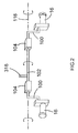
- two handles 16 which are connected to each other in a similar manner as to that shown in Figure 2 .
- Mounted within the motor housing 2 is an electric motor. Attached to the motor housing is a hammer mechanism housing in which is mounted a hammer mechanism. Hammer mechanisms for electrical pavement breakers are well known in the art and therefore will not be described in any more detail. EP1872913 describes an example of such a hammer mechanism. The hammer mechanism is driven by the electric motor.
- a tool holder Attached to the hammer mechanism housing, remote from the motor housing 2 is a tool holder.
- the tool holder is capable of holding a cutting tool.
- the hammer mechanism When the hammer mechanism is driven by motor, the hammer mechanism impart impacts onto the cutting tool when held in the tool holder.
- each handle 16 of a pavement in accordance with the embodiment of the present invention is rigidly connected via a link 100 to the end of a metal rod 102.
- the metal rod 102 passes through the motor housing 2.
- Formed along the rod 102 are two segments 104 which have a square cross section.
- Each of the segments 104 are mounted to a side panel 10 via a vibration dampener 106.
- Figure 4 shows part of a side panel 10, with an empty square aperture 114, and with a vibration dampener adjacent the panel 10.
- Figure 5 shows part of a side panel 10 with the vibration dampener 106 located within the square aperture 114 of the panel 10.
- each of the vibration dampeners comprise an inner rigid square tube 108 located within an outer rigid square tube 110, their longitudinal axes being parallel and co-axial. Sandwiched between them are four rubber rods 112 which are resilient in nature and are deformed by relative pivotal movement between the two tubes 108, 110.
- the rods 12 have a uniform shaped cross section along their lengths which is circular when not deformed.
- the rubber rods 12 are positioned so that the two square tubes 108, 110 are orientated by 45 degrees relative to each other about their longitudinal axes.
- the rubber rods 112 allow rotational movement between the inner and out square tubes 108, 110 over a limited range of movement about the longitudinal axes of the tubes.
- Each of the vibration dampeners 106 is located within a square aperture 114 formed in each side panel 10.
- the dimensions of each square aperture 114 corresponds with those of the outer square tubes 110. As such, initially, there is no movement between the outer square tube 110 and the panel 10.
- Each of the square segments 104 of the rod 102 has corresponding dimensions to the passageway 109 formed inside of the inner square tube 108.
- the square segments locate inside of the inner square tubes 108 of the vibration dampeners. As such there is no relative movement between the inner square tube 108 and the rod 102.
- the vibration dampeners reduce the amount of vibration transferred from the motor housing to the handles 16 by the rubber rods 12 absorbing vibration by allowing limited damped pivotal movement between the inner and outer square tubes 108, 110.
- a threaded bore 118 is provided in each of the panels which meet with the square apertures 114 (see Figure 3 ).
- a screw 120 can be screwed into each threaded bore 118 until it engages with the side of the outer square tube 110 as shown in Figure 5 .
- the screw 120 can be further screwed into the bore until presses tightly against the outer square tube 110 to prevent it moving inside of the square aperture 114.
- the screw 120 can subsequently be screwed out of the bore 118 to disengage it from the vibration dampener 106.
- the two links 100 extend in a generally horizontal direction when the pavement breaker is orientated vertically (with the longitudinal axis of the cutting tool 402 being vertical).
- the operator grasps the handles 16 and uses them to orientate the pavement breaker.
- the body of the pavement vibrates with the majority of the movement being in the vertical direction.
- the handles 16 pivot in a reciprocating manner about the longitudinal axis 16 of the rod 102, the handles 16 first moving to a position below the rod 102 and then to a position above the rod 102 before repeating the movement in a repetitive manner.
- the vibration dampeners 106 reduce the amount of vibration transferred to the handle 16 from the panels 10.
- the vibration dampeners allow the rod 102 to pivot between two extreme angular positions.
- the amount of movement of the panels 10 relative to the handles 16 under normal working conditions is such that the handles 16 do not move to such an extent that rod 102 pivots near to these to these extreme positions.
- the range of pivotal movement of the rod during is typically considerably less than the range between extreme positions, and rarely approaches these extreme positions.
- the operator will apply a downward pressure onto the handle in the belief that it will increase the force applied by the cutting tool on the work piece.
- the handles 16 will moving to a position which is further below the rod 102 and to a position which is a smaller amount above the rod 102.
- the rod 102 may pivot towards one of the extreme angular positions when the handles 16 are in their lowest position.
- an electric motor 300 which drives the hammer mechanism 318.
- the electric motor 300 is electrically connected to a motor controller 302 which controls the operation of the motor 300.
- the motor controller 302 is connected to a mains power supply 304 via a cable 306, a switch 308 mounted in one of the handles 16 and an electrical relay 310 mounted within the motor housing 2 as shown schematically in Figure 6 .
- the relay 310 is opened and closed by a micro switch 312 which is in electrical connection with the relay 310 and which is also mounted within the motor housing 2.
- the switch 308 in the handle 16 is connected to a pivotal lever 314 (similar to the pivotal lever 36 shown in Figure 1 ) mounted on the handle 16. Depression of the lever 314 by an operator operates the switch 308 in order to close the switch 308 and allow electric current to pass through it.
- Attached to the rod 102 which supports the handles 16 is a metal arm 316.
- the arm 316 extends in a direction parallel to the two links 100.
- the arm 316 similarly pivots, the end of the arm 316 moving up and down as it does so.
- the arm 316 is generally horizontal when the pavement breaker is in its normal operation orientation.
- the micro switch 312 Mounted in the motor housing 2, below the end of the arm 316, is the micro switch 312. When the handles 16 are raised towards their highest position, the end of the arm 316 pivots downwardly and engages with the micro switch 312. When the arm 316 is engaged with the micro switch 312, the micro switch is activated and sends an electrical signal to the relay 310. When the relay 310 receives the signal, the relay 310 opens and prevents any electric current from passing through the relay 310. When the arm 316 is not in contact with the micro switch 312, the micro switch 212 sends no signal to the relay 310. When the relay 310 receives no signal, the relay 310 closes, allowing electrical current to pass through the relay 310 with minimal resistance.
- the pavement breaker will be vertical with cutting tool is pointed downwardly in a vertical direction (and referred to as its normal operation orientation).
- the handles 16 pivot through a range of movement which results in the arm 316 making no contact with the micro switch 312.
- the relay 310 remains closed, allowing electrical current to pass through the relay 310 with minimal resistance. Therefore upon depression of the lever 314 by an operator, the switch 308 closes, allowing electric current to pass through it and the relay 310, switching the motor 300 on and activating the pavement breaker. As such, the operator can use the pavement breaker in the normal manner.
- the handles 16 When the operator picks up the pavement breaker using the handles 16 to move it, the handles 16 will pivotal towards their highest position (the pavement breaker being vertical with the cutting tool pointing downwardly due to the weight). When the handles 16 move towards their highest position, the end of the arm 316 will move downwardly and engage the micro switch 312. When the arm 316 is engaged with the micro switch 312, the micro switch 312 is activated and sends an electrical signal to the relay 310 which in turn causes the relay 310 to open and prevent and any electric current from passing through the relay 310. Therefore, if the operator accidentally depresses the lever 314 whilst moving the pavement breaker by the handles 16, the pavement breaker would be prevented from being activated by the relay 210 which is open.
- the pavement breaker would automatically switch off when the operator tries to lift the pavement breaker using the handles 16.
- a mechanical block can be located in the motor housing to prevent the arm 316 from damaging the micro switch 312 when the pavement breaker is lifted up by the handles 16.
- micro switch 312 could locate at apposition where it is only engaged when the handles 16 are moved to their extreme upper position rather approaching their extreme upper position.
- any type of switch device could used instead of a relay such as a solid state switch (a FET, bipolar transistor, triac, thyristor etc).
- a solid state switch a FET, bipolar transistor, triac, thyristor etc.
- the handles 16 may be biased towards their upper most position.
- the operator would have to apply a downward pressure onto the handles 16, to disengage the arm 316 from the micro switch 312, prior to the pavement breaker being able to be switched on using the lever 314.
- this would result in the operator constantly having to apply a downward pressure to the handles 16 in order to operate the pavement breaker.
Landscapes
- Engineering & Computer Science (AREA)
- Mechanical Engineering (AREA)
- Automation & Control Theory (AREA)
- Physics & Mathematics (AREA)
- Fluid Mechanics (AREA)
- Mining & Mineral Resources (AREA)
- Architecture (AREA)
- Civil Engineering (AREA)
- Structural Engineering (AREA)
- Percussive Tools And Related Accessories (AREA)
Abstract
Description
- The present invention relates to a pavement breaker.
-
EP1157788 discloses a typical hammer drill which can operate in a hammer only mode, a drill only mode and a combined hammer and drill mode. -
EP1872913 discloses a hammer drill which can operate in a hammer only mode which is often referred to as a pavement breaker. In addition to the fact that a pavement breaker only operates in one mode of operation when compared with a typical hammer drill, pavement breakers are much heavier than a typical hammer drill and therefore are usually operated in a limited range of angular positions with cutting tool generally pointing in a downward manner towards the work piece being cut (the "normal operation orientation"). In such an orientation, the weight of the pavement breaker is mainly supported by the cutting tool, the weight of the pavement breaker urging the cutting tool into the work piece being cut when the pavement breaker is in operation. As such, during the normal use of the pavement breaker, the support handles are used to orientate the pavement breaker, rather than support the weight of pavement as is normally the case on typical hammer drills. - The hammer mechanisms in pavement breakers are either driven by an electric motor or are powered by a pneumatic drive system. If the pavement breaker is driven by an electric motor, an electrical power source is supplied via an electric cable either from a mains power supply or a generator. Theoretically, a pavement breaker with an electric motor could be powered by a battery. However, battery technology is presently insufficiently developed to enable a practical design to be produced. If the pavement breaker is powered by a pneumatic drive system, a high pressure air source is supplied via a hose from a compressor.
- During the operation of such pavement breakers, a considerable amount of vibration can be generated. The vibration is caused by the operation of the hammer mechanism combined with the vibratory forces applied to and experienced by the cutting tool when it is being used on a work piece. These vibrations are transferred to the body of the pavement breaker, which in turn are transferred to the support handles being used by the operator to orientate the pavement breaker. The transfer of vibration to the support handles from the body, and subsequently to the operator's hands is not only painful but can result in injury, particularly when the pavement breaker is being used over long periods of time. It is therefore desirable to minimise the amount of vibration transferred from the body to the support handles.
- One solution is to moveably mount the support handles on the body of the pavement breaker to allow relative movement between the two and to locate a vibration dampening mechanism between the body and the support handles to minimise the amount of vibration transferred to the support handles from the body.
-
GB2468576 GB2468576 - When pavement breakers are moved around, they are often lifted up using the support handles and either placed on a trolley or vehicle for transportation, due to their weight, or to a new work piece which is to be cut by the pavement breaker. If the pavement breaker is being moved to a new work piece, the electrical power source or the high pressure air source often remains connected to the pavement breaker and is capable of providing power to drive the motor of the pavement breaker. One problem with this is that the pavement breaker can be accidentally switched on as the operator is moving the pavement breaker by the support handles. A pavement breaker is designed to be operated only when the cutting tool is pressing against a work piece. This is so that the striking force generated by the hammer mechanism is transferred through the cutting tool and into the work piece. If the pavement breaker is operated when the cutting is not engaged with a work piece, all of the energy of the hammer mechanism is imparted to the cutting tool only. This can result in damage to the pavement breaker as all of the energy has to be subsequently absorbed by the pavement breaker's tool holder which supports the cutting tool.
- Accordingly there is provided a pavement breaker in accordance with claim 1.
- Two embodiments of the present invention is now described with reference to the accompanying drawings of which:
-
Figure 1 shows drawing of a pavement breaker; -
Figure 2 shows a sketch of the handle; -
Figure 3 a cross sectional view of the side panel; -
Figure 4 shows the rotational vibration dampener separate from the side panel; -
Figure 5 shows the vibration dampener located in the side panel; -
Figure 6 shows a sketch of the handle mounted on the pavement breaker; and -
Figure 7 shows the electrical circuit of the pavement breaker. -
Figure 1 isFigure 7 ofEP1872913 which describes one type of pavement breaker. - Referring to
Figure 1 , the body of the pavement breaker comprises amotor housing 2 which is formed from acentral housing 8 and twoside panels 10 attached to the sides of thecentral housing 8 viascrews 14. Moveably mounted on themotor housing 2 are twohandles 16 which are connected to each other in a similar manner as to that shown inFigure 2 . Mounted within themotor housing 2 is an electric motor. Attached to the motor housing is a hammer mechanism housing in which is mounted a hammer mechanism. Hammer mechanisms for electrical pavement breakers are well known in the art and therefore will not be described in any more detail.EP1872913 describes an example of such a hammer mechanism. The hammer mechanism is driven by the electric motor. Attached to the hammer mechanism housing, remote from themotor housing 2 is a tool holder. The tool holder is capable of holding a cutting tool. When the hammer mechanism is driven by motor, the hammer mechanism impart impacts onto the cutting tool when held in the tool holder. - A first embodiment of the present invention will now be described with reference to
Figures 2 to 7 . - Referring to
Figure 2 , eachhandle 16 of a pavement in accordance with the embodiment of the present invention is rigidly connected via alink 100 to the end of ametal rod 102. Themetal rod 102 passes through themotor housing 2. Formed along therod 102 are twosegments 104 which have a square cross section. Each of thesegments 104 are mounted to aside panel 10 via avibration dampener 106. -
Figure 4 shows part of aside panel 10, with an emptysquare aperture 114, and with a vibration dampener adjacent thepanel 10.Figure 5 shows part of aside panel 10 with thevibration dampener 106 located within thesquare aperture 114 of thepanel 10. - Referring to
Figures 4 and5 , each of the vibration dampeners comprise an innerrigid square tube 108 located within an outer rigidsquare tube 110, their longitudinal axes being parallel and co-axial. Sandwiched between them are fourrubber rods 112 which are resilient in nature and are deformed by relative pivotal movement between the twotubes square tubes rubber rods 112 allow rotational movement between the inner and outsquare tubes - Each of the
vibration dampeners 106 is located within asquare aperture 114 formed in eachside panel 10. The dimensions of eachsquare aperture 114 corresponds with those of theouter square tubes 110. As such, initially, there is no movement between the outersquare tube 110 and thepanel 10. - Each of the
square segments 104 of therod 102 has corresponding dimensions to thepassageway 109 formed inside of the innersquare tube 108. The square segments locate inside of the innersquare tubes 108 of the vibration dampeners. As such there is no relative movement between the innersquare tube 108 and therod 102. - However, due to rubber rods 12 allowing relative movement between the inner and outer
square tubes rod 102 and thepanels 10 about thelongitudinal axis 116 of therod 102. Thus thehandles 16 can pivot about thelongitudinal axis 116 relative thepanels 10. - The vibration dampeners reduce the amount of vibration transferred from the motor housing to the
handles 16 by the rubber rods 12 absorbing vibration by allowing limited damped pivotal movement between the inner and outersquare tubes - However, over time, the shape of the
square apertures 114 in theside panels 10 become distorted due to the pressure applied via thehandles 16 on thepanels 10, allowing relative movement between the outersquare tube 110 and thepanels 10, thus allowing the vibration dampeners and handles to freely move. - Therefore, a threaded
bore 118 is provided in each of the panels which meet with the square apertures 114 (seeFigure 3 ). Ascrew 120 can be screwed into each threaded bore 118 until it engages with the side of the outersquare tube 110 as shown inFigure 5 . When thesquare apertures 114 in theside panels 10 become distorted, thescrew 120 can be further screwed into the bore until presses tightly against the outersquare tube 110 to prevent it moving inside of thesquare aperture 114. - The
screw 120 can subsequently be screwed out of thebore 118 to disengage it from thevibration dampener 106. - When no pressure is applied to the
handles 16, the twolinks 100 extend in a generally horizontal direction when the pavement breaker is orientated vertically (with the longitudinal axis of thecutting tool 402 being vertical). During the normal operation of the pavement breaker, the operator grasps thehandles 16 and uses them to orientate the pavement breaker. When the pavement breaker is operated, the body of the pavement vibrates with the majority of the movement being in the vertical direction. As the body vibrates, thehandles 16 pivot in a reciprocating manner about thelongitudinal axis 16 of therod 102, thehandles 16 first moving to a position below therod 102 and then to a position above therod 102 before repeating the movement in a repetitive manner. Thevibration dampeners 106 reduce the amount of vibration transferred to thehandle 16 from thepanels 10. The vibration dampeners allow therod 102 to pivot between two extreme angular positions. However the amount of movement of thepanels 10 relative to thehandles 16 under normal working conditions is such that thehandles 16 do not move to such an extent thatrod 102 pivots near to these to these extreme positions. The range of pivotal movement of the rod during is typically considerably less than the range between extreme positions, and rarely approaches these extreme positions. - Sometimes the operator will apply a downward pressure onto the handle in the belief that it will increase the force applied by the cutting tool on the work piece. In such circumstances, the
handles 16 will moving to a position which is further below therod 102 and to a position which is a smaller amount above therod 102. In such circumstances, therod 102 may pivot towards one of the extreme angular positions when thehandles 16 are in their lowest position. - Referring to
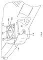
Figure 7 , mounted in themotor housing 2 is anelectric motor 300 which drives thehammer mechanism 318. Theelectric motor 300 is electrically connected to amotor controller 302 which controls the operation of themotor 300. Themotor controller 302 is connected to amains power supply 304 via acable 306, aswitch 308 mounted in one of thehandles 16 and anelectrical relay 310 mounted within themotor housing 2 as shown schematically inFigure 6 . Therelay 310 is opened and closed by amicro switch 312 which is in electrical connection with therelay 310 and which is also mounted within themotor housing 2. - The
switch 308 in thehandle 16 is connected to a pivotal lever 314 (similar to thepivotal lever 36 shown inFigure 1 ) mounted on thehandle 16. Depression of thelever 314 by an operator operates theswitch 308 in order to close theswitch 308 and allow electric current to pass through it. - Attached to the
rod 102 which supports thehandles 16 is ametal arm 316. Thearm 316 extends in a direction parallel to the twolinks 100. As therod 102 pivotal about theaxis 116, thearm 316 similarly pivots, the end of thearm 316 moving up and down as it does so. When no pressure is applied to thehandles 16, thearm 316 is generally horizontal when the pavement breaker is in its normal operation orientation. - Mounted in the
motor housing 2, below the end of thearm 316, is themicro switch 312. When thehandles 16 are raised towards their highest position, the end of thearm 316 pivots downwardly and engages with themicro switch 312. When thearm 316 is engaged with themicro switch 312, the micro switch is activated and sends an electrical signal to therelay 310. When therelay 310 receives the signal, therelay 310 opens and prevents any electric current from passing through therelay 310. When thearm 316 is not in contact with themicro switch 312, the micro switch 212 sends no signal to therelay 310. When therelay 310 receives no signal, therelay 310 closes, allowing electrical current to pass through therelay 310 with minimal resistance. - During the normal operation of the pavement breaker, the pavement breaker will be vertical with cutting tool is pointed downwardly in a vertical direction (and referred to as its normal operation orientation). During such operation, the
handles 16 pivot through a range of movement which results in thearm 316 making no contact with themicro switch 312. As such, therelay 310 remains closed, allowing electrical current to pass through therelay 310 with minimal resistance. Therefore upon depression of thelever 314 by an operator, theswitch 308 closes, allowing electric current to pass through it and therelay 310, switching themotor 300 on and activating the pavement breaker. As such, the operator can use the pavement breaker in the normal manner. - When the operator picks up the pavement breaker using the
handles 16 to move it, thehandles 16 will pivotal towards their highest position (the pavement breaker being vertical with the cutting tool pointing downwardly due to the weight). When thehandles 16 move towards their highest position, the end of thearm 316 will move downwardly and engage themicro switch 312. When thearm 316 is engaged with themicro switch 312, themicro switch 312 is activated and sends an electrical signal to therelay 310 which in turn causes therelay 310 to open and prevent and any electric current from passing through therelay 310. Therefore, if the operator accidentally depresses thelever 314 whilst moving the pavement breaker by thehandles 16, the pavement breaker would be prevented from being activated by the relay 210 which is open. - Similarly, if an operator decides to move the pavement breaker during its operation, the pavement breaker would automatically switch off when the operator tries to lift the pavement breaker using the
handles 16. - A mechanical block can be located in the motor housing to prevent the
arm 316 from damaging themicro switch 312 when the pavement breaker is lifted up by thehandles 16. - It will be appreciated that
micro switch 312 could locate at apposition where it is only engaged when thehandles 16 are moved to their extreme upper position rather approaching their extreme upper position. - It will be further appreciated that any type of switch device could used instead of a relay such as a solid state switch (a FET, bipolar transistor, triac, thyristor etc).
- In an alternative embodiment, the
handles 16 may be biased towards their upper most position. In such a design, the operator would have to apply a downward pressure onto thehandles 16, to disengage thearm 316 from themicro switch 312, prior to the pavement breaker being able to be switched on using thelever 314. However, this would result in the operator constantly having to apply a downward pressure to thehandles 16 in order to operate the pavement breaker. - Whilst the invention has been described in relation to a pavement breaker powered by an electric motor, it will be appreciated that the invention is also applicable to a pneumatic pavement breaker where the hammer mechanism is driven via a pneumatic drive system. Pneumatic drive systems and hammer mechanisms for pneumatic pavement breakers are well known in the art.
Claims (8)
- A pavement breaker comprising:a housing (2);a hammer mechanism (318) mounted within the housing (2);at least one handle (16) moveably mounted on the housing (2) and which is capable of moving in at least in a vertical direction when the pavement breaker is orientated in its normal operation orientation;characterised in that there is a sensor (312) mounted within the housing (2) which is capable of detecting when the at least one handle (16) is moved towards or into its uppermost position; andwherein, when the at least one handle (16) is moved towards or into its uppermost position, the sensor (312) prevents the activation of the hammer mechanism (318) when it detects that the at least one handle (16) has moved towards or is in its uppermost position.
- A pavement breaker according to claim 1 wherein the at least one handle (16) is pivotally mounted on the housing (2).
- A pavement breaker according to either of claims 1 or 2 wherein the at least one handle (16) can move through a range of vertical positions between an uppermost position and a lowest position; and
wherein the at least one handle (16) is biased to a position between its uppermost position and its lowest position. - A pavement breaker according to claim 3 wherein the at least one handle (16) is biased to a position midway between its uppermost position and its lowest position.
- A pavement breaker according to either of claims 1 or 2 wherein the at least one handle (16) can move through a range of vertical positions between an uppermost position and a lowest position; and
wherein the at least one handle (16) is biased to its uppermost position. - A pavement breaker according to any of the previous claims wherein the hammer mechanism (318) is driven either by an electric motor (300) or by a pneumatic drive system; and
wherein the sensor (312) prevents the activation the electric motor (300) or pneumatic drive system when it detects that the at least one handle (16) has moved towards or is in its uppermost position in order to prevent the activation of the hammer mechanism (318). - A pavement breaker according to any one of the previous claims wherein there is an arm (316) connected to and moveable with the at least one handle(16); and
wherein the sensor (312) is a micro switch which is engaged by the arm (316) when the at least one handle (16) is moved towards or into its uppermost position. - A pavement breaker according to any one of the previous claims wherein the hammer mechanism (318) is driven either by an electric motor (300) or by a pneumatic drive system;
wherein the operation of the electric motor (300) or pneumatic drive system is controlled by a controller (302); and
wherein the sensor (312) sends a signal to the controller (302) when it detects that the at least one handle (16) has moved towards or is in its uppermost position, the controller (302) preventing the activation the electric motor (300) or pneumatic drive system upon receipt of the signal in order to prevent the activation of the hammer mechanism (318).
Applications Claiming Priority (1)
| Application Number | Priority Date | Filing Date | Title |
|---|---|---|---|
| GBGB1518088.8A GB201518088D0 (en) | 2015-10-13 | 2015-10-13 | Pavement Breaker |
Publications (1)
| Publication Number | Publication Date |
|---|---|
| EP3156184A1 true EP3156184A1 (en) | 2017-04-19 |
Family
ID=55130972
Family Applications (1)
| Application Number | Title | Priority Date | Filing Date |
|---|---|---|---|
| EP16192414.7A Withdrawn EP3156184A1 (en) | 2015-10-13 | 2016-10-05 | Pavement breaker |
Country Status (3)
| Country | Link |
|---|---|
| US (1) | US11739481B2 (en) |
| EP (1) | EP3156184A1 (en) |
| GB (1) | GB201518088D0 (en) |
Families Citing this family (17)
| Publication number | Priority date | Publication date | Assignee | Title |
|---|---|---|---|---|
| GB201518088D0 (en) * | 2015-10-13 | 2015-11-25 | Black & Decker Inc | Pavement Breaker |
| GB2564712B (en) * | 2017-07-21 | 2020-01-29 | Webster Tech Limited | Power Tool |
| CN107288022A (en) * | 2017-08-19 | 2017-10-24 | 荆门创佳机械科技有限公司 | A kind of disintegrating machine of linear electric motors driving |
| CN109112941A (en) * | 2018-08-16 | 2019-01-01 | 广东省建筑工程机械施工有限公司 | A kind of municipal road pavement crushing construction method |
| EP3822032A1 (en) | 2019-11-14 | 2021-05-19 | Hilti Aktiengesellschaft | Method for controlling and regulating a machine tool and handle for machine tool |
| EP3822034A1 (en) | 2019-11-14 | 2021-05-19 | Hilti Aktiengesellschaft | Method for controlling and regulating a machine tool |
| EP3822035A1 (en) * | 2019-11-14 | 2021-05-19 | Hilti Aktiengesellschaft | Handle device for a machine tool |
| EP3822031A1 (en) * | 2019-11-14 | 2021-05-19 | Hilti Aktiengesellschaft | Method for controlling and regulating a machine tool |
| EP3822033A1 (en) | 2019-11-14 | 2021-05-19 | Hilti Aktiengesellschaft | Method for controlling and regulating a machine tool |
| DE102020206450A1 (en) * | 2020-05-25 | 2021-11-25 | Robert Bosch Gesellschaft mit beschränkter Haftung | Hand machine tool |
| BR112023000137A2 (en) * | 2020-07-07 | 2023-03-14 | Seti Tec | MULTITASKING DEVICE |
| US20220032436A1 (en) * | 2020-07-31 | 2022-02-03 | Separation Equipment Co Inc | Locking Ring Impactor Apparatus |
| US20230026934A1 (en) * | 2021-07-26 | 2023-01-26 | Makita Corporation | Striking tool |
| US20230027574A1 (en) * | 2021-07-26 | 2023-01-26 | Makita Corporation | Striking tool |
| DE102021134593A1 (en) * | 2021-12-23 | 2023-06-29 | Klingelnberg Gmbh | machine tool and process |
| US12569970B2 (en) | 2022-02-02 | 2026-03-10 | Makita Corporation | Power tool having hammer mechanism |
| CN221048350U (en) * | 2023-09-14 | 2024-05-31 | 米沃奇电动工具公司 | Vibration damping structure for power tool and power tool with vibration damping structure |
Citations (7)
| Publication number | Priority date | Publication date | Assignee | Title |
|---|---|---|---|---|
| GB242218A (en) * | 1924-10-29 | 1926-03-11 | Ingersoll Rand Co | Improvement in pneumatic hammer tool |
| GB714300A (en) * | 1952-05-05 | 1954-08-25 | Arthur Abbey | Improvements in or relating to control devices for motor driven hand tools |
| DE3610682A1 (en) * | 1986-03-29 | 1987-10-01 | Bosch Gmbh Robert | Handle for hand-held machine tools |
| DE102005028918A1 (en) * | 2005-06-22 | 2006-12-28 | Wacker Construction Equipment Ag | Drilling and/or percussive hammer for making holes has delay device controlling valve during closing |
| GB2468576A (en) * | 2009-03-12 | 2010-09-15 | Black & Decker Inc | Hammer drill with dampened handle |
| EP2324961A2 (en) * | 2009-11-19 | 2011-05-25 | Makita Corporation | Hand-held tool |
| DE102012005803A1 (en) * | 2012-03-21 | 2013-09-26 | Wacker Neuson Produktion GmbH & Co. KG | Drilling and / or hammer with load-dependent adaptation of the stroke rate |
Family Cites Families (45)
| Publication number | Priority date | Publication date | Assignee | Title |
|---|---|---|---|---|
| USRE23104E (en) * | 1949-04-26 | Percussion tool | ||
| GB340870A (en) | 1929-03-14 | 1931-01-08 | Siemens Ag | Improvements in or relating to handle switches for electro-tools |
| US1887762A (en) * | 1931-06-29 | 1932-11-15 | Archibald M Mcneil | Pavement breaker |
| US2676464A (en) * | 1946-04-12 | 1954-04-27 | Charles F Warren Jr | Hydraulic impact pulsator transmission system |
| US2672129A (en) * | 1949-03-17 | 1954-03-16 | Chicago Pneumatic Tool Co | Chipping hammer |
| US2630784A (en) * | 1949-06-20 | 1953-03-10 | Lord Mfg Co | Cushion handle for percussive tools |
| US2906244A (en) * | 1958-02-24 | 1959-09-29 | Sheldon L Christensen | Hydraulic pavement breaker |
| US2984210A (en) * | 1958-07-15 | 1961-05-16 | Thor Power Tool Co | Shock-absorbing handle structure for pneumatic tools |
| DE1855677U (en) | 1960-12-03 | 1962-07-26 | Artur Fischer | IMPACT DRILL. |
| US3179185A (en) * | 1962-06-14 | 1965-04-20 | Chicago Pneumatic Tool Co | Demolition tool with shock attenuating means |
| GB1055048A (en) * | 1964-10-19 | 1967-01-11 | Atlas Copco Ab | Improvements in noise deadening means for percussive tools |
| US3559753A (en) * | 1969-05-21 | 1971-02-02 | Ilmar Meri | Percussion tool |
| DE6931913U (en) | 1969-08-13 | 1972-08-31 | Wacker Werke Kg | SPEED REGULATING DEVICE ON WORK EQUIPMENT WITH BACK AND BACK WORK MOVEMENT OF THE TOOL, PREFERABLY HANDHAMMER. |
| US3824417A (en) * | 1973-03-19 | 1974-07-16 | Black & Decker Mfg Co | Handle mounting construction for electric paving breaker |
| US4440237A (en) * | 1982-06-11 | 1984-04-03 | Ingersoll-Rand Co. | Pavement breaker |
| DE3447401A1 (en) * | 1984-12-24 | 1986-07-03 | Wacker-Werke Gmbh & Co Kg, 8077 Reichertshofen | HAMMER WITH COVER |
| JPH0673826B2 (en) * | 1988-05-27 | 1994-09-21 | 協和合金株式会社 | Anti-vibration handle device |
| US5107911A (en) * | 1991-05-06 | 1992-04-28 | Plakotaris Vincent A | Log splitting device |
| US5369236A (en) | 1992-10-01 | 1994-11-29 | Black & Decker Inc. | Control switch arrangement for orbital polisher |
| US5273120A (en) * | 1993-05-26 | 1993-12-28 | Ingersoll-Rand Company | Power tool with a vibration absorbing handle |
| SE504957C2 (en) * | 1994-02-28 | 1997-06-02 | Berema Atlas Copco Ab | Machine skewer with handle fitted back piece |
| FI963326L (en) * | 1994-02-28 | 1996-08-27 | Berema Atlas Copco Ab | Valve arrangement of a compressed air engine |
| US5524715A (en) * | 1994-07-29 | 1996-06-11 | Ingersoll-Rand Company | Throttle lever system for a fluid-activated, percussive paving breaker |
| US5524714A (en) * | 1994-07-29 | 1996-06-11 | Ingersoll-Rand Company | System for lubricating and reciprocating a piston in a fluid-activated, percussive paving breaker |
| SE9501340L (en) * | 1995-04-11 | 1996-06-24 | Berema Atlas Copco Ab | Claims for motor-driven percussion |
| EP1166972A3 (en) * | 2000-06-27 | 2004-01-21 | Framatome Connectors International | Power tool trigger linkage |
| DE10232934A1 (en) | 2002-07-19 | 2004-01-29 | Ident Technology Ag | Handle device and safety circuit arrangement, in particular for a power tool |
| DE10316844A1 (en) * | 2003-04-11 | 2004-11-04 | Hilti Ag | Control of an electric hand machine tool |
| GB2402098B (en) * | 2003-05-21 | 2007-10-17 | Black & Decker Inc | Vibration reduction apparatus for power tool and power tool incorporating such apparatus |
| SE529839C2 (en) * | 2005-05-26 | 2007-12-04 | Atlas Copco Constr Tools Ab | Switching tool with vibrated handle device |
| DE102005000207A1 (en) * | 2005-12-23 | 2007-06-28 | Hilti Ag | Hand-held power tool e.g. pneumatic chisel, has handle suspensions arranged in housing in such way that suspensions do not cause additional constructional length, and rings provided between pivot axes and suspensions, respectively |
| DE102006000207A1 (en) * | 2006-04-28 | 2007-10-31 | Hilti Ag | Hand tool with adjustable handles |
| ATE482031T1 (en) * | 2006-07-01 | 2010-10-15 | Black & Decker Inc | DEMOLITION HAMMER |
| US7413026B2 (en) * | 2006-07-01 | 2008-08-19 | Black & Decker Inc. | Lubricant system for powered hammer |
| EP1872913B1 (en) * | 2006-07-01 | 2015-08-19 | Black & Decker, Inc. | A tool holder for a hammer apparatus |
| DE102006061575A1 (en) * | 2006-12-27 | 2008-07-03 | Robert Bosch Gmbh | Internal combustion engine crank shaft rotation angle determining method for use by sensor i.e. differential sensor, involves incrementing half increment with sign of rotational direction before rotary direction reversal |
| DE102007000408A1 (en) * | 2007-07-27 | 2009-01-29 | Hilti Aktiengesellschaft | Hand tool |
| DE102007000454A1 (en) * | 2007-11-09 | 2009-05-14 | Hilti Aktiengesellschaft | Striking hand tool with contactless handset in side handle |
| DE102008050323A1 (en) | 2008-10-04 | 2010-04-08 | Protool Gmbh | Hand machine tool with a handle arrangement |
| DE102010032351A1 (en) | 2010-07-27 | 2012-02-02 | Wacker Neuson Produktion GmbH & Co. KG | Hand-guided implement with operator recognition device |
| DE102011078082B4 (en) | 2011-06-27 | 2022-08-11 | Robert Bosch Gmbh | Hand tool machine, in particular drilling or screwing device |
| DE102012210101A1 (en) * | 2012-06-15 | 2013-12-19 | Hilti Aktiengesellschaft | control method |
| DE102012210088A1 (en) * | 2012-06-15 | 2013-12-19 | Hilti Aktiengesellschaft | machine tool |
| JP6125392B2 (en) * | 2013-09-27 | 2017-05-10 | 株式会社マキタ | Impact tool |
| GB201518088D0 (en) * | 2015-10-13 | 2015-11-25 | Black & Decker Inc | Pavement Breaker |
-
2015
- 2015-10-13 GB GBGB1518088.8A patent/GB201518088D0/en not_active Ceased
-
2016
- 2016-10-05 EP EP16192414.7A patent/EP3156184A1/en not_active Withdrawn
- 2016-10-07 US US15/287,885 patent/US11739481B2/en active Active
Patent Citations (7)
| Publication number | Priority date | Publication date | Assignee | Title |
|---|---|---|---|---|
| GB242218A (en) * | 1924-10-29 | 1926-03-11 | Ingersoll Rand Co | Improvement in pneumatic hammer tool |
| GB714300A (en) * | 1952-05-05 | 1954-08-25 | Arthur Abbey | Improvements in or relating to control devices for motor driven hand tools |
| DE3610682A1 (en) * | 1986-03-29 | 1987-10-01 | Bosch Gmbh Robert | Handle for hand-held machine tools |
| DE102005028918A1 (en) * | 2005-06-22 | 2006-12-28 | Wacker Construction Equipment Ag | Drilling and/or percussive hammer for making holes has delay device controlling valve during closing |
| GB2468576A (en) * | 2009-03-12 | 2010-09-15 | Black & Decker Inc | Hammer drill with dampened handle |
| EP2324961A2 (en) * | 2009-11-19 | 2011-05-25 | Makita Corporation | Hand-held tool |
| DE102012005803A1 (en) * | 2012-03-21 | 2013-09-26 | Wacker Neuson Produktion GmbH & Co. KG | Drilling and / or hammer with load-dependent adaptation of the stroke rate |
Also Published As
| Publication number | Publication date |
|---|---|
| GB201518088D0 (en) | 2015-11-25 |
| US20170101747A1 (en) | 2017-04-13 |
| US11739481B2 (en) | 2023-08-29 |
Similar Documents
| Publication | Publication Date | Title |
|---|---|---|
| US11739481B2 (en) | Pavement breaker | |
| US11413736B2 (en) | Hand-held power tool | |
| KR101535295B1 (en) | Pruning shears | |
| US20180345469A1 (en) | Reciprocating work machine | |
| EP2647463B1 (en) | Ultrasonic welding device with a pick member and/or a press pad, and method of operating said device | |
| CN210256010U (en) | Accessories for power hammers and power hammer assemblies | |
| EP3562632A2 (en) | Gripper apparatus | |
| CN107253032B (en) | The assembly device of hose and clip | |
| CA2411180A1 (en) | Adjustable support assembly for a data entry/interface device for computers or the like | |
| CN103538066A (en) | Mechanical arm achieving automatic matching | |
| KR101444386B1 (en) | Multi-link finger module of robot hand | |
| US10265878B2 (en) | Material handling system and method of use | |
| US12589468B2 (en) | Electric vise | |
| KR20180044881A (en) | Hand guide device for setting a setting element and method of using the device | |
| CN110253607A (en) | A kind of manipulator of adjustable grip strength | |
| JP2011230228A (en) | Motor-driven chuck | |
| CN203603762U (en) | Drill rod conveying device for drill jumbo | |
| CN108000550A (en) | Glass pieces mechanism for picking and laser-processing system | |
| CN207983236U (en) | A kind of DR component heights adjustment tooling | |
| CA2644861A1 (en) | Stop block for stamping presses | |
| CN105057491A (en) | Safety hand with adjustable magnetic force | |
| KR101741689B1 (en) | Easily detachable magnets-integrated end-effector for cable robot | |
| US12195287B2 (en) | Robot system and method of operating the same | |
| CN219031719U (en) | Automatic filling machine is with spiral cover equipment | |
| CN210704906U (en) | Multifunctional end manipulator of industrial robot |
Legal Events
| Date | Code | Title | Description |
|---|---|---|---|
| PUAI | Public reference made under article 153(3) epc to a published international application that has entered the european phase |
Free format text: ORIGINAL CODE: 0009012 |
|
| AK | Designated contracting states |
Kind code of ref document: A1 Designated state(s): AL AT BE BG CH CY CZ DE DK EE ES FI FR GB GR HR HU IE IS IT LI LT LU LV MC MK MT NL NO PL PT RO RS SE SI SK SM TR |
|
| AX | Request for extension of the european patent |
Extension state: BA ME |
|
| 17P | Request for examination filed |
Effective date: 20170505 |
|
| RBV | Designated contracting states (corrected) |
Designated state(s): AL AT BE BG CH CY CZ DE DK EE ES FI FR GB GR HR HU IE IS IT LI LT LU LV MC MK MT NL NO PL PT RO RS SE SI SK SM TR |
|
| 17Q | First examination report despatched |
Effective date: 20191111 |
|
| STAA | Information on the status of an ep patent application or granted ep patent |
Free format text: STATUS: THE APPLICATION IS DEEMED TO BE WITHDRAWN |
|
| 18D | Application deemed to be withdrawn |
Effective date: 20200603 |