EP3156145B1 - Molded material production method and molded material - Google Patents
Molded material production method and molded material Download PDFInfo
- Publication number
- EP3156145B1 EP3156145B1 EP15805752.1A EP15805752A EP3156145B1 EP 3156145 B1 EP3156145 B1 EP 3156145B1 EP 15805752 A EP15805752 A EP 15805752A EP 3156145 B1 EP3156145 B1 EP 3156145B1
- Authority
- EP
- European Patent Office
- Prior art keywords
- flange
- formed material
- punch
- thickness
- base metal
- Prior art date
- Legal status (The legal status is an assumption and is not a legal conclusion. Google has not performed a legal analysis and makes no representation as to the accuracy of the status listed.)
- Active
Links
- 239000000463 material Substances 0.000 title claims description 59
- 238000004519 manufacturing process Methods 0.000 title claims description 24
- 238000000034 method Methods 0.000 claims description 118
- 238000010409 ironing Methods 0.000 claims description 41
- 239000010953 base metal Substances 0.000 claims description 35
- 230000000052 comparative effect Effects 0.000 description 6
- 238000005259 measurement Methods 0.000 description 6
- 238000012545 processing Methods 0.000 description 5
- 238000007747 plating Methods 0.000 description 3
- 239000013585 weight reducing agent Substances 0.000 description 3
- 229910018134 Al-Mg Inorganic materials 0.000 description 2
- 229910018467 Al—Mg Inorganic materials 0.000 description 2
- 229910000831 Steel Inorganic materials 0.000 description 2
- 239000010960 cold rolled steel Substances 0.000 description 2
- 238000005336 cracking Methods 0.000 description 2
- 238000003780 insertion Methods 0.000 description 2
- 230000037431 insertion Effects 0.000 description 2
- 230000013011 mating Effects 0.000 description 2
- 239000002184 metal Substances 0.000 description 2
- NRNCYVBFPDDJNE-UHFFFAOYSA-N pemoline Chemical compound O1C(N)=NC(=O)C1C1=CC=CC=C1 NRNCYVBFPDDJNE-UHFFFAOYSA-N 0.000 description 2
- 230000002093 peripheral effect Effects 0.000 description 2
- 238000003825 pressing Methods 0.000 description 2
- 239000010959 steel Substances 0.000 description 2
- 230000037303 wrinkles Effects 0.000 description 2
- 239000000956 alloy Substances 0.000 description 1
- 229910045601 alloy Inorganic materials 0.000 description 1
- 230000015572 biosynthetic process Effects 0.000 description 1
- 238000007906 compression Methods 0.000 description 1
- 238000007796 conventional method Methods 0.000 description 1
- 230000001419 dependent effect Effects 0.000 description 1
- 238000011161 development Methods 0.000 description 1
- 230000018109 developmental process Effects 0.000 description 1
- 230000000694 effects Effects 0.000 description 1
- 238000011156 evaluation Methods 0.000 description 1
- 239000012467 final product Substances 0.000 description 1
- 201000009240 nasopharyngitis Diseases 0.000 description 1
- 238000000059 patterning Methods 0.000 description 1
- 239000000047 product Substances 0.000 description 1
- 238000006748 scratching Methods 0.000 description 1
- 230000002393 scratching effect Effects 0.000 description 1
- 238000005549 size reduction Methods 0.000 description 1
- 239000010935 stainless steel Substances 0.000 description 1
- 229910001220 stainless steel Inorganic materials 0.000 description 1
- 230000008719 thickening Effects 0.000 description 1
Images


Classifications
-
- B—PERFORMING OPERATIONS; TRANSPORTING
- B21—MECHANICAL METAL-WORKING WITHOUT ESSENTIALLY REMOVING MATERIAL; PUNCHING METAL
- B21D—WORKING OR PROCESSING OF SHEET METAL OR METAL TUBES, RODS OR PROFILES WITHOUT ESSENTIALLY REMOVING MATERIAL; PUNCHING METAL
- B21D22/00—Shaping without cutting, by stamping, spinning, or deep-drawing
- B21D22/20—Deep-drawing
- B21D22/28—Deep-drawing of cylindrical articles using consecutive dies
-
- B—PERFORMING OPERATIONS; TRANSPORTING
- B21—MECHANICAL METAL-WORKING WITHOUT ESSENTIALLY REMOVING MATERIAL; PUNCHING METAL
- B21D—WORKING OR PROCESSING OF SHEET METAL OR METAL TUBES, RODS OR PROFILES WITHOUT ESSENTIALLY REMOVING MATERIAL; PUNCHING METAL
- B21D22/00—Shaping without cutting, by stamping, spinning, or deep-drawing
- B21D22/20—Deep-drawing
- B21D22/21—Deep-drawing without fixing the border of the blank
-
- B—PERFORMING OPERATIONS; TRANSPORTING
- B21—MECHANICAL METAL-WORKING WITHOUT ESSENTIALLY REMOVING MATERIAL; PUNCHING METAL
- B21D—WORKING OR PROCESSING OF SHEET METAL OR METAL TUBES, RODS OR PROFILES WITHOUT ESSENTIALLY REMOVING MATERIAL; PUNCHING METAL
- B21D22/00—Shaping without cutting, by stamping, spinning, or deep-drawing
- B21D22/20—Deep-drawing
- B21D22/30—Deep-drawing to finish articles formed by deep-drawing
-
- B—PERFORMING OPERATIONS; TRANSPORTING
- B21—MECHANICAL METAL-WORKING WITHOUT ESSENTIALLY REMOVING MATERIAL; PUNCHING METAL
- B21D—WORKING OR PROCESSING OF SHEET METAL OR METAL TUBES, RODS OR PROFILES WITHOUT ESSENTIALLY REMOVING MATERIAL; PUNCHING METAL
- B21D35/00—Combined processes according to or processes combined with methods covered by groups B21D1/00 - B21D31/00
- B21D35/002—Processes combined with methods covered by groups B21D1/00 - B21D31/00
- B21D35/005—Processes combined with methods covered by groups B21D1/00 - B21D31/00 characterized by the material of the blank or the workpiece
- B21D35/006—Blanks having varying thickness, e.g. tailored blanks
Definitions
- This invention relates to a formed material manufacturing method for manufacturing a formed material having a tubular body and a flange formed at an end of the body with the features of the preamble of claim 1.
- a formed material having a tubular body and a flange formed at an end of the body is manufactured by performing a drawing process. Since the body is formed by stretching a base metal sheet in the drawing process, the thickness of the body is less than that of the base sheet. Meanwhile, since the region of the metal sheet corresponding to the flange shrinks as a whole in response to the formation of the body, the flange thickness is larger than that of the base sheet.
- the abovementioned formed material can be used as the motor case disclosed, for example, in PTL 1.
- the body is expected to function as a shielding material that prevents magnetic leakage to the outside of the motor case.
- the body is also expected to function as a back yoke of a stator.
- the performance of the body as the shield material or back yoke is improved as the thickness thereof increases. Therefore, when a formed material is manufactured by drawing, as described hereinabove, a base metal sheet with a thickness larger than the necessary thickness of the body is selected in consideration of the reduction in thickness caused by the drawing process. Meanwhile, the flange is most often used for mounting the motor case on the mounting object. Therefore, the flange is expected to have a certain strength.
- the flange of the formed material is expected to have a uniform thickness and highly accurate flatness.
- KR 2010 0093704 A discloses a formed material manufacturing method with the features of the preamble of claim 1.
- the flange thickness is larger than that of the base sheet. For this reason, the flange sometimes becomes unnecessarily thick and has a thickness in excess of that needed to obtain the performance expected from the flange. It means that the formed material becomes unnecessarily heavy, which cannot be ignored in applications in which weight reduction is required, such as motor cases.
- thickness reduction of the flange by pressing can be also considered for obtaining a uniform flange thickness or realizing a highly accurate flange flatness.
- the flange thickness increases gradually towards the outer circumference thereof, the thickness is preferentially reduced close to the thick outer circumference, and a uniform thickness is difficult to obtain for the entire flange.
- a high-power press is needed. Therefore, a restriction is placed on the press that can be used.
- the present invention has been created to resolve the abovementioned problems, and it is an objective of the present invention to provide a formed material manufacturing method by which unnecessary thickening of the flange can be avoided, a formed material can be reduced in weight, a base metal sheet can be reduced in size, uniformity of flange thickness can be improved, and a highly accurate flatness can be obtained, and also to provide a formed material.
- the ironing process is performed on the region corresponding to the flange of the base metal sheet by pushing the base metal sheet together with the punch into the pushing hole in the drawing-out process, and the coining process is performed by inserting the flange between the pushing mold and receiving mold and compressing. Therefore, an unnecessary increase in the thickness of the flange can be avoided, the formed material can be reduced in weight, the uniformity of the thickness of the flange can be improved, and a highly accurate flatness can be obtained. Further, since the thickness of the flange is reduced by the ironing process, the press power necessary for the coining process can be greatly reduced, and the processing can be expected to be performed with a press machine that is lower in power than those in the conventional processing. This configuration is particularly useful in applications in which weight reduction is required, such as motor cases.
- Fig. 1 is a perspective view showing a formed material 1 manufactured by a formed material manufacturing method according to Embodiment 1 of the present invention.
- the formed material 1 manufactured by the formed material manufacturing method according to the present embodiment includes a body 10 and a flange 11.
- the body 10 is a tubular part having a top wall 100 and a circumferential wall 101 that extends from an outer edge of the top wall 100.
- the top wall 100 may be referred to using another term, such as a bottom wall.
- the body 10 is shown to have a perfectly circular sectional shape, but the body 10 may have another shape, for example, such as an elliptical sectional shape or angular tubular shape.
- the top wall 100 may be subjected to further processing. For example, a protrusion projecting from the top wall 100 can be formed.
- the flange 11 is a sheet portion formed on an end (an end of the circumferential wall 101) of the body 10.
- Fig. 2 is a sectional view taken along a line II-II in Fig. 1 .
- a sheet thickness t 11 of the flange 11 is less than a sheet thickness t 101 of the circumferential wall 101 of the body 10.
- the reason for this, as will be described in detail hereinbelow, is that the ironing process is performed on a region of a base metal sheet 2 (see Fig. 3 ) corresponding to the flange 11.
- the sheet thickness t 11 of the flange 11, as referred to herein, means an average value of the sheet thickness of the flange 11 from a lower end of a lower side shoulder portion Rd between the circumferential wall 101 and the flange 11 and an outer end of the flange 11.
- the sheet thickness t 101 of the circumferential wall 101 means an average value of the sheet thickness of the circumferential wall 101 from an upper end of the lower side shoulder portion Rd to a lower end of an upper side shoulder portion Rp.
- Fig. 3 is an explanatory drawing illustrating the formed material manufacturing method for manufacturing the formed material 1 depicted in Fig. 1 .
- the formed material 1 is manufactured by performing at least three forming processes on the flat base metal sheet 2.
- the at least three forming processes include at least one drawing-out process, at least one drawing process performed after the drawing-out process, and at least one coining process performed after the drawing process.
- the formed material 1 is manufactured by one drawing-out process, three drawing processes (first to third drawing processes), and one coining process.
- Various types of metal sheets such as a cold-rolled steel sheet, a stainless steel sheet, and a plated steel sheet, can be used as the base metal sheet 2.
- Fig. 4 is an explanatory drawing illustrating a mold 3 used in the drawing-out process depicted in Fig. 3
- Fig. 5 is an explanatory drawing illustrating the drawing-out process performed with the mold 3 depicted in Fig. 4
- the mold 3 used in the drawing-out process includes a die 30, a punch 31, and a cushion pad 32.
- a pushing hole 30a into which the base metal sheet 2 is pushed together with the punch 31 is provided in the die 30.
- the cushion pad 32 is disposed at an outer peripheral position of the punch 31 so as to face an outer end surface of the die 30.
- an outer edge portion of the base metal sheet 2 is not completely constrained by the die 30 and the cushion pad 32, and the outer edge portion of the base metal sheet 2 is drawn out until it escapes from the constraint applied thereto by the die 30 and the cushion pad 32.
- the entire base metal sheet 2 may be pushed together with the punch 31 into the pushing hole 30a and drawn out.
- Fig. 6 is an explanatory drawing illustrating in greater detail the punch 31 depicted in Fig. 4 .
- a width w 311 of a rear end side 311 of the punch 31 used in the drawing-out process is greater than a width w 310 of a tip end side 310 of the punch 31.
- a width of the pushing hole 30a is set to be substantially uniform along an insertion direction in which the punch 31 is inserted into the pushing hole 30a. In other words, an inner wall of the die 30 extends substantially parallel to the insertion direction of the punch 31.
- a clearance c 30-31 between the die 30 and the punch 31 in a state in which the punch 31 is pushed into the pushing hole 30a is narrower on the rear end side 311 of the punch 31 than on the tip end side 310 of the punch 31.
- the clearance c 30-31 on the rear end side 311 of the punch 31 is set to be narrower than the sheet thickness of the base metal sheet 2 before the drawing-out process is performed. Therefore, as a result of pushing the base metal sheet 2 together with the punch 31 into the pushing hole 30a in the drawing-out process, the ironing process is performed on the outer edge portion of the base metal sheet 2, that is, on a region of the base metal sheet 2 corresponding to the flange 11. The ironing process reduces the sheet thickness of the region corresponding to the flange 11 (makes the region thinner).
- a width variation portion 31a configured of an inclined surface on which a width of the punch 31 varies continuously is provided between the tip end side 310 and the rear end side 311 of the punch 31.
- the width variation portion 31a is disposed such as to be in contact with a region of the base metal sheet 2 corresponding to the lower side shoulder portion Rd (see Fig. 2 ) between the width variation portion 31a and the inner wall of the die 30 when the base metal sheet 2 is pushed together with the punch 31 into the pushing hole 30a in the drawing-out process.
- Fig. 7 is an explanatory drawing illustrating the mold 4 used in the first drawing process illustrated by Fig. 3 .
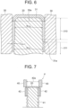
- Fig. 8 is an explanatory drawing illustrating the first drawing process performed with the mold 4 depicted in Fig. 7 .
- the mold 4 used in the first drawing process includes a die 40, a punch 41, and a drawing sleeve 42.
- a pushing hole 40a into which a first intermediate body 20, which is formed in the above-described drawing-out process, is pushed together with the punch 41 is provided in the die 40.
- the drawing sleeve 42 is disposed at an outer peripheral position of the punch 41 so as to face an outer end surface of the die 40.
- Fig. 7 is an explanatory drawing illustrating the mold 4 used in the first drawing process illustrated by Fig. 3 .
- Fig. 8 is an explanatory drawing illustrating the first drawing process performed with the mold 4 depicted in Fig. 7 .
- the mold 4 used in the first drawing process includes a die 40
- the drawing process is performed on a region of the first intermediate body 20 corresponding to the body 10, and the flange 11 is formed by constraining an outer edge portion of the first intermediate body 20 by the die 40 and the drawing sleeve 42.
- the purpose of the sleeve 42 is to prevent the occurrence of wrinkles during the drawing, and the sleeve 42 may be omitted when no wrinkle occurs.
- the second and third drawing processes depicted in Fig. 3 can be implemented using a conventional mold (such an implementation is not illustrated by the drawings).
- the drawing process is further performed on a region of a second intermediate body 21 (see Fig. 3 ) formed in the first drawing process, this region corresponding to the body 10.
- the third drawing process corresponds to a re-striking process, in which the ironing process is performed on a region of a third intermediate body 22 (see Fig. 3 ) formed in the second drawing process, this region corresponding to the body 10.
- shrinkage occurs in the region corresponding to the flange 11, and an increase in the thickness occurs in this region.
- An amount by which the sheet thickness of the region corresponding to the flange 11 is reduced in the drawing-out process can be adjusted, as appropriate, by changing the clearance c 30-31 on the rear end side 311 of the punch 31 of the mold 3 used in the drawing-out process.
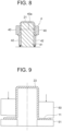
- Fig. 9 is an explanatory drawing illustrating a mold used in the coining process of the flange illustrated by Fig. 3 .
- Fig. 9 illustrates the states before and after the coining process, those states being separated by the dot-dash line in the center.
- the mold includes a pushing mold 50 (upper mold) for coining and a receiving mold 51 (lower mold) that receives the pushing mold 50.
- a step corresponding to the flange shape of the final product is provided at the pushing mold 50.
- the flange 11 of the fourth intermediate body 23 formed in the drawing process is inserted between the pushing mold 50 and the receiving mold 51 and receives a pushing pressure, whereby the flange region necessary for the product is compressed and reduced in thickness. A portion of the flange 11 which is not compressed in the coining process is trimmed after the coining process.
- the flange 11 is a part formed from the outer edge portion of the base metal sheet 2 in the drawing process.
- the region corresponding to the flange 11 when the drawing-out process is performed on the base metal sheet 2 is reduced in thickness by the ironing process. Therefore, the flange 11 of the formed body 1 which is manufactured by the formed body manufacturing method according to the present invention is less in thickness than the flange of the usual formed body. For this reason, the coining process can be performed even by using a press machine which is less powerful than that in the conventional methods.
- the coining process is a compression process in which a pressure from about several tons to, in some cases, a high pressure in excess of 100 tons is applied to a workpiece.
- the workpiece is generally also patterned by the coining process, but the coining process of the present embodiment may be performed without patterning the flange 11.
- the inventors of the present application performed the drawing-out process under the following processing conditions by using, as the base metal sheet 2, a round sheet having a thickness of 1.8 mm and a diameter of 116 mm and formed by implementing Zn-Al-Mg plating on a common cold-rolled steel sheet.
- the Zn-Al-Mg alloy plating was implemented on both surfaces of the steel sheet, and a plating coverage was 90 g/m 2 on each surface.
- the processing could be performed without problems. Meanwhile, when the ironing ratio was greater than 30% and equal to or less than 50% (when the diameter of the rear end side 311 of the punch 31 was greater than 67.5 mm and equal to or less than 68.2 mm), a slight scratching mark was found at a portion that slides against the die 30. Further, when the ironing ratio exceeded 50% (when the diameter of the rear end side 311 of the punch 31 was greater than 67.9 mm), seizure and cracking occurred against the inner wall of the die 30.
- the ironing ratio of the region corresponding to the flange 11 in the drawing-out process is preferably equal to or less than 50%, and more preferably equal to or less than 30%.
- the ironing ratio is defined as ⁇ [(pre-ironing sheet thickness) - (post-ironing sheet thickness)]/(pre-ironing sheet thickness) ⁇ ⁇ 100.
- a value of the sheet thickness of the base metal sheet can be used as the pre-ironing sheet thickness.
- Fig. 10 is a graph showing the difference in sheet thickness of the first intermediate body 20 occurring when an ironing ratio is changed.
- Fig. 11 is an explanatory drawing illustrating the sheet thickness measurement positions depicted in Fig. 10.
- Fig. 10 shows the sheet thickness of the first intermediate body 20 when the drawing-out process was performed at an ironing ratio of -20% (testpiece A; a comparative example) and the sheet thickness of the first intermediate body 20 when the drawing-out process was performed at an ironing ratio of 30% (testpiece B). As shown in Fig.
- Fig. 12 is a graph showing the sheet thickness of the formed materials 1 manufactured from respective first intermediate bodies 20 (testpiece A and testpiece B) depicted in Fig. 10 .
- Fig. 13 is an explanatory drawing illustrating the sheet thickness measurement positions depicted in Fig. 12 .
- testpiece A comparative example
- the drawing process was performed on the first intermediate body 20(testpiece A depicted in Fig. 10 ) on which the drawing-out process was performed without ironing, and the coining process was not performed on the flange 11.
- testpiece B1 comparative example
- the drawing process was performed on the first intermediate body 20 (testpiece B depicted in Fig. 10 ) on which the drawing-out process including ironing was performed, and the coining process was not performed on the flange 11.
- testpiece B2 (example of the invention) depicted in Fig. 12
- the drawing process was performed on the first intermediate body 20 (testpiece B depicted in Fig. 10 ) on which the drawing-out process including ironing was performed, and the coining process was performed on the flange 11.
- the thickness of the flange 11 in the final formed material 1 is generally reduced.
- the sheet thickness of the flange 11 is not uniform.
- the sheet thickness of the flange 11 is uniform. Further, when the formed material 1 (testpiece B1 or testpiece B2) subjected to the drawing-out process that included ironing and the formed material 1 (testpiece A) which was not subjected to the drawing-out process that included ironing had the same dimensions, the weight of the testpiece B1 or B2 was about 10% less than the weight of the testpiece A.
- a drawing-out process including ironing When a drawing-out process including ironing is performed, the region of the base metal sheet 2 corresponding to the flange 11 is stretched.
- a smaller base metal sheet 2 may be used while taking into consideration, in advance, an amount by which the region corresponding to the flange 11 is stretched, or an unnecessary portion of the flange 11 may be trimmed.
- the ironing process is performed on the region of the base metal sheet 2 corresponding to the flange 11 in the drawing-out process by pushing the base metal sheet 2 together with the punch 31 into the pushing hole 30a, and therefore an unnecessary increase in the thickness of the flange 11 can be avoided and the formed material 1 can be reduced in weight. Further, by performing the coining process on the flange 11 after the drawing process, it is possible obtain the flange with highly accurate thin sheet thickness and flatness. This configuration is particularly useful in applications in which weight reduction of the formed material, size reduction of the base metal sheet, and a highly accurate thin flange are required, such as motor cases.
- the ironing ratio of the ironing process performed during the drawing-out process is equal to or less than 50%, and therefore the occurrence of seizure and cracking can be avoided.
- the drawing-out process is performed only once, but two or more drawing-out processes may be performed before the drawing process.
- the thickness of the flange 11 can be reduced more reliably.
- a plurality of drawing-out processes is particularly effective when the base metal sheet 2 is thick.
- the ironing ratio of each process is still preferably set to be equal to or less than 50% to avoid seizure and the like. Further, by setting the ironing ratio to be equal to or less than 30%, scratch marks can also be avoided.
- the drawing process is performed three times, but the number of the drawing processes may be changed, as appropriate, according to the size and required dimensional accuracy of the formed material 1.
Description
- This invention relates to a formed material manufacturing method for manufacturing a formed material having a tubular body and a flange formed at an end of the body with the features of the preamble of
claim 1. - As disclosed, for example, in
NPL 1, a formed material having a tubular body and a flange formed at an end of the body is manufactured by performing a drawing process. Since the body is formed by stretching a base metal sheet in the drawing process, the thickness of the body is less than that of the base sheet. Meanwhile, since the region of the metal sheet corresponding to the flange shrinks as a whole in response to the formation of the body, the flange thickness is larger than that of the base sheet. - The abovementioned formed material can be used as the motor case disclosed, for example, in
PTL 1. Here, the body is expected to function as a shielding material that prevents magnetic leakage to the outside of the motor case. In some motor structures, the body is also expected to function as a back yoke of a stator. The performance of the body as the shield material or back yoke is improved as the thickness thereof increases. Therefore, when a formed material is manufactured by drawing, as described hereinabove, a base metal sheet with a thickness larger than the necessary thickness of the body is selected in consideration of the reduction in thickness caused by the drawing process. Meanwhile, the flange is most often used for mounting the motor case on the mounting object. Therefore, the flange is expected to have a certain strength. - Further, when a formed material is mounted on a mating member such as a chassis or panel, good adherence (air tightness) is sometimes needed between the forming material and the mating member. In such cases, the flange of the formed material is expected to have a uniform thickness and highly accurate flatness.
- [PTL 1]
Japanese Patent Application Publication No. 2013-51765 KR 2010 0093704 A claim 1. - [NPL 1]
"Basics of Plastic Forming", Masao Murakawa and three others, First Edition, SANGYO-TOSHO Publishing Co. Ltd., January 16, 1990, pp. 104 to 107 - However, with the conventional formed material manufacturing method such as described hereinabove, since the formed material having a tubular body and a flange formed at the end of the body is manufactured by the drawing process, the flange thickness is larger than that of the base sheet. For this reason, the flange sometimes becomes unnecessarily thick and has a thickness in excess of that needed to obtain the performance expected from the flange. It means that the formed material becomes unnecessarily heavy, which cannot be ignored in applications in which weight reduction is required, such as motor cases.
- Further, thickness reduction of the flange by pressing can be also considered for obtaining a uniform flange thickness or realizing a highly accurate flange flatness. However, since the flange thickness increases gradually towards the outer circumference thereof, the thickness is preferentially reduced close to the thick outer circumference, and a uniform thickness is difficult to obtain for the entire flange. In addition, where such flange is made thinner by pressing, a high-power press is needed. Therefore, a restriction is placed on the press that can be used.
- The present invention has been created to resolve the abovementioned problems, and it is an objective of the present invention to provide a formed material manufacturing method by which unnecessary thickening of the flange can be avoided, a formed material can be reduced in weight, a base metal sheet can be reduced in size, uniformity of flange thickness can be improved, and a highly accurate flatness can be obtained, and also to provide a formed material.
- The invention is defined in
claim 1. Further developments are given in the dependent claims. - With the formed material manufacturing method according to the present invention, the ironing process is performed on the region corresponding to the flange of the base metal sheet by pushing the base metal sheet together with the punch into the pushing hole in the drawing-out process, and the coining process is performed by inserting the flange between the pushing mold and receiving mold and compressing. Therefore, an unnecessary increase in the thickness of the flange can be avoided, the formed material can be reduced in weight, the uniformity of the thickness of the flange can be improved, and a highly accurate flatness can be obtained. Further, since the thickness of the flange is reduced by the ironing process, the press power necessary for the coining process can be greatly reduced, and the processing can be expected to be performed with a press machine that is lower in power than those in the conventional processing. This configuration is particularly useful in applications in which weight reduction is required, such as motor cases.
-
- [
Fig. 1 ]
Fig. 1 is a perspective view showing a formed material manufactured by a formed material manufacturing method according toEmbodiment 1 of the present invention. - [
Fig. 2 ]
Fig. 2 is a sectional view taken along a II-II line inFig. 1 . - [
Fig. 3 ]
Fig. 3 is an explanatory drawing illustrating the formed material manufacturing method for manufacturing the formed material depicted inFig. 1 . - [
Fig. 4 ]
Fig. 4 is an explanatory drawing illustrating a mold used in a drawing-out process depicted inFig. 3 . - [
Fig. 5 ]
Fig. 5 is an explanatory drawing illustrating the drawing-out process performed with the mold depicted inFig. 4 . - [
Fig. 6 ]
Fig. 6 is an explanatory drawing illustrating in greater detail the punch depicted inFig. 4 . - [
Fig. 7 ]
Fig. 7 is an explanatory drawing illustrating the mold used in the first drawing process illustrated byFig. 3 . - [
Fig. 8 ]
Fig. 8 is an explanatory drawing illustrating the first drawing process performed with the mold depicted inFig. 7 . - [
Fig. 9 ]
Fig. 9 is an explanatory drawing illustrating a mold used in the coining process illustrated byFig. 3 . - [
Fig. 10 ]
Fig. 10 is a graph showing the difference in sheet thickness of a first intermediate body occurring when an ironing ratio is changed. - [
Fig. 11 ]
Fig. 11 is an explanatory drawing illustrating the sheet thickness measurement positions depicted inFig. 10 . - [
Fig. 12 ]
Fig. 12 is a graph showing the sheet thickness of the formed materials manufactured from respective first intermediate bodies depicted inFig. 10 . - [
Fig. 13 ]
Fig. 13 is an explanatory drawing illustrating the sheet thickness measurement positions depicted inFig. 12 . - Embodiments of the present invention will be described below with reference to the drawings.
-
Fig. 1 is a perspective view showing a formedmaterial 1 manufactured by a formed material manufacturing method according toEmbodiment 1 of the present invention. As shown inFig. 1 , the formedmaterial 1 manufactured by the formed material manufacturing method according to the present embodiment includes abody 10 and aflange 11. Thebody 10 is a tubular part having atop wall 100 and acircumferential wall 101 that extends from an outer edge of thetop wall 100. Depending on the orientation in which the formedmaterial 1 is to be used, thetop wall 100 may be referred to using another term, such as a bottom wall. InFig. 1 , thebody 10 is shown to have a perfectly circular sectional shape, but thebody 10 may have another shape, for example, such as an elliptical sectional shape or angular tubular shape. Thetop wall 100 may be subjected to further processing. For example, a protrusion projecting from thetop wall 100 can be formed. Theflange 11 is a sheet portion formed on an end (an end of the circumferential wall 101) of thebody 10. -
Fig. 2 is a sectional view taken along a line II-II inFig. 1 . As shown inFig. 2 , a sheet thickness t11 of theflange 11 is less than a sheet thickness t101 of thecircumferential wall 101 of thebody 10. The reason for this, as will be described in detail hereinbelow, is that the ironing process is performed on a region of a base metal sheet 2 (seeFig. 3 ) corresponding to theflange 11. The sheet thickness t11 of theflange 11, as referred to herein, means an average value of the sheet thickness of theflange 11 from a lower end of a lower side shoulder portion Rd between thecircumferential wall 101 and theflange 11 and an outer end of theflange 11. Similarly, the sheet thickness t101 of thecircumferential wall 101 means an average value of the sheet thickness of thecircumferential wall 101 from an upper end of the lower side shoulder portion Rd to a lower end of an upper side shoulder portion Rp. -
Fig. 3 is an explanatory drawing illustrating the formed material manufacturing method for manufacturing the formedmaterial 1 depicted inFig. 1 . In the formed material manufacturing method according to the present invention, the formedmaterial 1 is manufactured by performing at least three forming processes on the flatbase metal sheet 2. The at least three forming processes include at least one drawing-out process, at least one drawing process performed after the drawing-out process, and at least one coining process performed after the drawing process. In the formed material manufacturing method according to this embodiment, the formedmaterial 1 is manufactured by one drawing-out process, three drawing processes (first to third drawing processes), and one coining process. Various types of metal sheets, such as a cold-rolled steel sheet, a stainless steel sheet, and a plated steel sheet, can be used as thebase metal sheet 2. -
Fig. 4 is an explanatory drawing illustrating amold 3 used in the drawing-out process depicted inFig. 3 , andFig. 5 is an explanatory drawing illustrating the drawing-out process performed with themold 3 depicted inFig. 4 . As shown inFig. 4 , themold 3 used in the drawing-out process includes a die 30, apunch 31, and acushion pad 32. A pushinghole 30a into which thebase metal sheet 2 is pushed together with thepunch 31 is provided in thedie 30. Thecushion pad 32 is disposed at an outer peripheral position of thepunch 31 so as to face an outer end surface of thedie 30. As shown inFig. 5 , in the drawing-out process, an outer edge portion of thebase metal sheet 2 is not completely constrained by thedie 30 and thecushion pad 32, and the outer edge portion of thebase metal sheet 2 is drawn out until it escapes from the constraint applied thereto by thedie 30 and thecushion pad 32. The entirebase metal sheet 2 may be pushed together with thepunch 31 into the pushinghole 30a and drawn out. -
Fig. 6 is an explanatory drawing illustrating in greater detail thepunch 31 depicted inFig. 4 . As shown inFig. 6 , a width w311 of arear end side 311 of thepunch 31 used in the drawing-out process is greater than a width w310 of atip end side 310 of thepunch 31. Meanwhile a width of the pushinghole 30a is set to be substantially uniform along an insertion direction in which thepunch 31 is inserted into the pushinghole 30a. In other words, an inner wall of the die 30 extends substantially parallel to the insertion direction of thepunch 31. - Thus, as shown in
Fig. 6 , a clearance c30-31 between the die 30 and thepunch 31 in a state in which thepunch 31 is pushed into the pushinghole 30a is narrower on therear end side 311 of thepunch 31 than on thetip end side 310 of thepunch 31. The clearance c30-31 on therear end side 311 of thepunch 31 is set to be narrower than the sheet thickness of thebase metal sheet 2 before the drawing-out process is performed. Therefore, as a result of pushing thebase metal sheet 2 together with thepunch 31 into the pushinghole 30a in the drawing-out process, the ironing process is performed on the outer edge portion of thebase metal sheet 2, that is, on a region of thebase metal sheet 2 corresponding to theflange 11. The ironing process reduces the sheet thickness of the region corresponding to the flange 11 (makes the region thinner). - A
width variation portion 31a configured of an inclined surface on which a width of thepunch 31 varies continuously is provided between thetip end side 310 and therear end side 311 of thepunch 31. Thewidth variation portion 31a is disposed such as to be in contact with a region of thebase metal sheet 2 corresponding to the lower side shoulder portion Rd (seeFig. 2 ) between thewidth variation portion 31a and the inner wall of the die 30 when thebase metal sheet 2 is pushed together with thepunch 31 into the pushinghole 30a in the drawing-out process. -
Fig. 7 is an explanatory drawing illustrating themold 4 used in the first drawing process illustrated byFig. 3 .Fig. 8 is an explanatory drawing illustrating the first drawing process performed with themold 4 depicted inFig. 7 . As shown inFig. 7 , themold 4 used in the first drawing process includes a die 40, apunch 41, and adrawing sleeve 42. A pushinghole 40a into which a firstintermediate body 20, which is formed in the above-described drawing-out process, is pushed together with thepunch 41 is provided in thedie 40. The drawingsleeve 42 is disposed at an outer peripheral position of thepunch 41 so as to face an outer end surface of thedie 40. As shown inFig. 8 , in the first drawing process, the drawing process is performed on a region of the firstintermediate body 20 corresponding to thebody 10, and theflange 11 is formed by constraining an outer edge portion of the firstintermediate body 20 by thedie 40 and the drawingsleeve 42. The purpose of thesleeve 42 is to prevent the occurrence of wrinkles during the drawing, and thesleeve 42 may be omitted when no wrinkle occurs. - The second and third drawing processes depicted in
Fig. 3 can be implemented using a conventional mold (such an implementation is not illustrated by the drawings). In the second drawing process, the drawing process is further performed on a region of a second intermediate body 21 (seeFig. 3 ) formed in the first drawing process, this region corresponding to thebody 10. The third drawing process corresponds to a re-striking process, in which the ironing process is performed on a region of a third intermediate body 22 (seeFig. 3 ) formed in the second drawing process, this region corresponding to thebody 10. - In the first to third drawing processes, shrinkage occurs in the region corresponding to the
flange 11, and an increase in the thickness occurs in this region. However, by reducing sufficiently the sheet thickness of the region corresponding to theflange 11 in the drawing-out process, it is possible to make the sheet thickness t11 of theflange 11 less than the sheet thickness t101 of thecircumferential wall 101 of thebody 10 in the final formedmaterial 1. An amount by which the sheet thickness of the region corresponding to theflange 11 is reduced in the drawing-out process can be adjusted, as appropriate, by changing the clearance c30-31 on therear end side 311 of thepunch 31 of themold 3 used in the drawing-out process. -
Fig. 9 is an explanatory drawing illustrating a mold used in the coining process of the flange illustrated byFig. 3 .Fig. 9 illustrates the states before and after the coining process, those states being separated by the dot-dash line in the center. As depicted inFig. 9 , the mold includes a pushing mold 50 (upper mold) for coining and a receiving mold 51 (lower mold) that receives the pushingmold 50. A step corresponding to the flange shape of the final product is provided at the pushingmold 50. Theflange 11 of the fourthintermediate body 23 formed in the drawing process is inserted between the pushingmold 50 and the receivingmold 51 and receives a pushing pressure, whereby the flange region necessary for the product is compressed and reduced in thickness. A portion of theflange 11 which is not compressed in the coining process is trimmed after the coining process. - The
flange 11 is a part formed from the outer edge portion of thebase metal sheet 2 in the drawing process. In theintermediate bodies 20 to 22 manufactured by the formed material manufacturing method according to the present invention, the region corresponding to theflange 11 when the drawing-out process is performed on thebase metal sheet 2 is reduced in thickness by the ironing process. Therefore, theflange 11 of the formedbody 1 which is manufactured by the formed body manufacturing method according to the present invention is less in thickness than the flange of the usual formed body. For this reason, the coining process can be performed even by using a press machine which is less powerful than that in the conventional methods. The coining process, as referred to herein, is a compression process in which a pressure from about several tons to, in some cases, a high pressure in excess of 100 tons is applied to a workpiece. The workpiece is generally also patterned by the coining process, but the coining process of the present embodiment may be performed without patterning theflange 11. - Next, examples will be described. The inventors of the present application performed the drawing-out process under the following processing conditions by using, as the
base metal sheet 2, a round sheet having a thickness of 1.8 mm and a diameter of 116 mm and formed by implementing Zn-Al-Mg plating on a common cold-rolled steel sheet. Here, the Zn-Al-Mg alloy plating was implemented on both surfaces of the steel sheet, and a plating coverage was 90 g/m2 on each surface. - Ironing ratio of region corresponding to flange 11: - 20% to 60%
- Curvature radius of mold 3: 6 mm
- Diameter of pushing
hole 30a: 70 mm - Diameter of
tip end side 310 of punch 31: 65.7 mm - Diameter of
rear end side 311 of punch 31: 65.7 mm to 68.6 mm - Shape of
width variation portion 31a: inclined surface - Position of
width variation portion 31a: region corresponding to lower side shoulder portion Rd - Coining process: no, yes (500 kN)
- Press oil: TN-20
- <Evaluation of ironing ratio>
- When the ironing ratio was 30% or less (when the diameter of the
rear end side 311 of thepunch 31 was 67.5 mm or less), the processing could be performed without problems. Meanwhile, when the ironing ratio was greater than 30% and equal to or less than 50% (when the diameter of therear end side 311 of thepunch 31 was greater than 67.5 mm and equal to or less than 68.2 mm), a slight scratching mark was found at a portion that slides against thedie 30. Further, when the ironing ratio exceeded 50% (when the diameter of therear end side 311 of thepunch 31 was greater than 67.9 mm), seizure and cracking occurred against the inner wall of thedie 30. It is, therefore, clear that the ironing ratio of the region corresponding to theflange 11 in the drawing-out process is preferably equal to or less than 50%, and more preferably equal to or less than 30%. The ironing ratio is defined as {[(pre-ironing sheet thickness) - (post-ironing sheet thickness)]/(pre-ironing sheet thickness)} ×100. Here, a value of the sheet thickness of the base metal sheet can be used as the pre-ironing sheet thickness. -
Fig. 10 is a graph showing the difference in sheet thickness of the firstintermediate body 20 occurring when an ironing ratio is changed. Further,Fig. 11 is an explanatory drawing illustrating the sheet thickness measurement positions depicted inFig. 10. Fig. 10 shows the sheet thickness of the firstintermediate body 20 when the drawing-out process was performed at an ironing ratio of -20% (testpiece A; a comparative example) and the sheet thickness of the firstintermediate body 20 when the drawing-out process was performed at an ironing ratio of 30% (testpiece B). As shown inFig. 10 , when the drawing-out process was performed at an ironing ratio of 30% (testpiece B), the sheet thickness in the region corresponding to the flange 11 (measurement positions 50 to 70) was less than the sheet thickness (1.8 mm) of thebase metal sheet 2. Meanwhile, when the drawing-out process was performed at an ironing ratio of -20% (testpiece A), the sheet thickness in the region corresponding to the flange 11 (measurement positions 50 to 70) was larger than the sheet thickness (1.8 mm) of thebase metal sheet 2. - Further,
Fig. 12 is a graph showing the sheet thickness of the formedmaterials 1 manufactured from respective first intermediate bodies 20 (testpiece A and testpiece B) depicted inFig. 10 .Fig. 13 is an explanatory drawing illustrating the sheet thickness measurement positions depicted inFig. 12 . - In the testpiece A (comparative example) depicted in
Fig. 12 , the drawing process was performed on the first intermediate body 20(testpiece A depicted inFig. 10 ) on which the drawing-out process was performed without ironing, and the coining process was not performed on theflange 11. - In the testpiece B1 (comparative example) depicted in
Fig. 12 , the drawing process was performed on the first intermediate body 20 (testpiece B depicted inFig. 10 ) on which the drawing-out process including ironing was performed, and the coining process was not performed on theflange 11. - In the testpiece B2 (example of the invention) depicted in
Fig. 12 , the drawing process was performed on the first intermediate body 20 (testpiece B depicted inFig. 10 ) on which the drawing-out process including ironing was performed, and the coining process was performed on theflange 11. - As depicted in
Fig. 12 , differences in the sheet thickness at the stage of the firstintermediate body 20 appear, without changes, also in the formedmaterial 1. In other words, in the testpiece A (comparative example), the sheet thickness of theflange 11 in the final formedmaterial 1 is larger than the sheet thickness of the body in the formed material. - In the testpiece B1 (comparative example), the thickness of the
flange 11 in the final formedmaterial 1 is generally reduced. However, the sheet thickness of theflange 11 is not uniform. - Meanwhile, in the testpiece B2 (example of the invention), it is clear that the sheet thickness of the
flange 11 is uniform.
Further, when the formed material 1 (testpiece B1 or testpiece B2) subjected to the drawing-out process that included ironing and the formed material 1 (testpiece A) which was not subjected to the drawing-out process that included ironing had the same dimensions, the weight of the testpiece B1 or B2 was about 10% less than the weight of the testpiece A. - When a drawing-out process including ironing is performed, the region of the
base metal sheet 2 corresponding to theflange 11 is stretched. In order to form the formedmaterial 1 subjected to the drawing-out process including ironing (example of the invention) and the formedmaterial 1 not subjected to the drawing-out process including ironing (comparative example) at identical dimensions, either a smallerbase metal sheet 2 may be used while taking into consideration, in advance, an amount by which the region corresponding to theflange 11 is stretched, or an unnecessary portion of theflange 11 may be trimmed. - In such formed material manufacturing method and the formed
material 1 manufactured thereby, the ironing process is performed on the region of thebase metal sheet 2
corresponding to theflange 11 in the drawing-out process by pushing thebase metal sheet 2 together with thepunch 31 into the pushinghole 30a, and therefore an unnecessary increase in the thickness of theflange 11 can be avoided and the formedmaterial 1 can be reduced in weight. Further, by performing the coining process on theflange 11 after the drawing process, it is possible obtain the flange with highly accurate thin sheet thickness and flatness. This configuration is particularly useful in applications in which weight reduction of the formed material, size reduction of the base metal sheet, and a highly accurate thin flange are required, such as motor cases. - Further, the ironing ratio of the ironing process performed during the drawing-out process is equal to or less than 50%, and therefore the occurrence of seizure and cracking can be avoided.
- In the embodiment described above, the drawing-out process is performed only once, but two or more drawing-out processes may be performed before the drawing process. By performing a plurality of drawing-out processes, the thickness of the
flange 11 can be reduced more reliably. A plurality of drawing-out processes is particularly effective when thebase metal sheet 2 is thick. Even when a plurality of drawing-out processes is performed, the ironing ratio of each process is still preferably set to be equal to or less than 50% to avoid seizure and the like. Further, by setting the ironing ratio to be equal to or less than 30%, scratch marks can also be avoided. - Further, in the embodiment described above, the drawing process is performed three times, but the number of the drawing processes may be changed, as appropriate, according to the size and required dimensional accuracy of the formed
material 1.
Claims (4)
- A formed material manufacturing method of manufacturing a formed material (1) having a tubular body (10) and a flange (11), which is formed at an end of the body (10), by performing at least three forming processes on a base metal sheet (2), whereinthe at least three forming processes include at least one drawing-out process, at least one drawing process performed after the drawing-out process, and at least one coining process performed after the drawing process,characterized in thatthe drawing-out process is performed on the base metal sheet (2) using a mold (3) that includes a punch (31) and a die (30) having a pushing hole (30a) so that a first intermediate body (20) is formed,a width of a rear end side of the punch (31) is set to be wider than a width of a tip end side thereof so that a clearance between the die (30) and the punch (31), when the punch (31) is pushed into the pushing hole (30a) in the die (30), is narrower on the rear end side than on the tip end side,an ironing process is performed on a region corresponding to the flange (11) of the base metal sheet (2) by pushing the base metal sheet (2) together with the punch (31) into the pushing hole (30a) in the drawing-out process, andin the coining process, the flange (11) formed in the drawing process is inserted between a pushing mold (50) and a receiving mold (51), wherein the flange (11) is compressed and reduced in thickness.
- The formed material manufacturing method according to claim 1, wherein
an ironing ratio of the ironing process is 50% or less. - The formed material manufacturing method according to claim 1 or 2, wherein
the coining process is performed on a part where the ironing process has been performed in the drawing-out process. - The formed material manufacturing method according to any one of claims 1 to 3, wherein
the thickness of the flange (11) of the formed material is less than that of the base metal sheet (2).
Applications Claiming Priority (2)
| Application Number | Priority Date | Filing Date | Title |
|---|---|---|---|
| JP2014122298A JP6352065B2 (en) | 2014-06-13 | 2014-06-13 | Molding material manufacturing method |
| PCT/JP2015/053373 WO2015190125A1 (en) | 2014-06-13 | 2015-02-06 | Molded material production method and molded material |
Publications (3)
| Publication Number | Publication Date |
|---|---|
| EP3156145A1 EP3156145A1 (en) | 2017-04-19 |
| EP3156145A4 EP3156145A4 (en) | 2018-02-28 |
| EP3156145B1 true EP3156145B1 (en) | 2023-04-05 |
Family
ID=54833236
Family Applications (1)
| Application Number | Title | Priority Date | Filing Date |
|---|---|---|---|
| EP15805752.1A Active EP3156145B1 (en) | 2014-06-13 | 2015-02-06 | Molded material production method and molded material |
Country Status (15)
| Country | Link |
|---|---|
| US (1) | US11117178B2 (en) |
| EP (1) | EP3156145B1 (en) |
| JP (1) | JP6352065B2 (en) |
| KR (1) | KR102268395B1 (en) |
| CN (1) | CN106660099B (en) |
| AU (1) | AU2015272926B2 (en) |
| BR (1) | BR112016028168B1 (en) |
| CA (1) | CA2951785C (en) |
| EA (1) | EA034328B1 (en) |
| MX (1) | MX2016016178A (en) |
| MY (1) | MY176499A (en) |
| PH (1) | PH12016502366A1 (en) |
| SG (1) | SG11201609688QA (en) |
| TW (1) | TWI681826B (en) |
| WO (1) | WO2015190125A1 (en) |
Families Citing this family (5)
| Publication number | Priority date | Publication date | Assignee | Title |
|---|---|---|---|---|
| WO2017145856A1 (en) * | 2016-02-22 | 2017-08-31 | 日新製鋼株式会社 | Molding material production method and molding material thereof |
| KR101935759B1 (en) * | 2016-02-23 | 2019-01-04 | 닛신 세이코 가부시키가이샤 | Molding material manufacturing method and molding material thereof |
| US10894283B2 (en) | 2016-02-24 | 2021-01-19 | Nisshin Steel Co., Ltd. | Molded material production method and molded material |
| MY176104A (en) * | 2016-03-03 | 2020-07-24 | Nisshin Steel Co Ltd | Method for manufacturing molded member |
| JP7133803B2 (en) * | 2018-08-01 | 2022-09-09 | 日立Astemo株式会社 | Manufacturing method of housing for rotary electric machine |
Citations (1)
| Publication number | Priority date | Publication date | Assignee | Title |
|---|---|---|---|---|
| EP3015184A1 (en) * | 2014-03-20 | 2016-05-04 | Nisshin Steel Co., Ltd. | Molded material manufacturing method and molded material |
Family Cites Families (27)
| Publication number | Priority date | Publication date | Assignee | Title |
|---|---|---|---|---|
| US3682122A (en) * | 1970-09-28 | 1972-08-08 | Aluminum Co Of America | Method and apparatus for forming heat exchange fin collars |
| BE795263A (en) * | 1972-02-11 | 1973-05-29 | K M Engineering A G | MANUFACTURING PROCESS WITHOUT REMOVAL OF CHIPS FROM STEEL SHEET CONTAINERS |
| US3855862A (en) * | 1973-04-23 | 1974-12-24 | Continental Can Co | Draw and wall iron process for metal cans |
| US3945231A (en) * | 1973-10-31 | 1976-03-23 | Toyo Seikan Kaisha Limited | Process and apparatus for preparation of thin walled cylindrical vessels |
| US4522049A (en) * | 1983-03-14 | 1985-06-11 | Aluminum Company Of America | Aluminum alloy food can body and method for making same |
| US4562719A (en) * | 1983-09-23 | 1986-01-07 | Verson Allsteel Press Company | Method for drawing heavy wall shells with a multi-step inside edge |
| JPH07106394B2 (en) * | 1989-05-17 | 1995-11-15 | 東洋製罐株式会社 | Squeeze ironing can manufacturing method |
| GB2245855B (en) * | 1989-11-13 | 1993-09-22 | Toyo Seikan Kaisha Ltd | Method of redrawing flanged cup |
| US5329799A (en) * | 1992-05-29 | 1994-07-19 | Toyota Jidosha Kabushiki Kaisha | Process and apparatus for press-forming tubular container-like article from strip, including forward and backward ironing steps |
| US5501092A (en) * | 1993-07-14 | 1996-03-26 | Hidaka Seiki Kabushiki Kaisha | Die-punch machine |
| TW252961B (en) * | 1994-02-15 | 1995-08-01 | Toyo Seikan Kaisha Ltd | Method of producing seamless cans |
| JP3579936B2 (en) * | 1994-11-21 | 2004-10-20 | トヨタ自動車株式会社 | Molding method for bottomed tubular products |
| US6038910A (en) | 1998-12-30 | 2000-03-21 | Can Industry Products, Inc. | Method and apparatus for forming tapered metal container bodies |
| JP4397503B2 (en) * | 2000-03-30 | 2010-01-13 | アスモ株式会社 | Method for manufacturing a yoke of a rotating electric machine |
| US6701603B2 (en) * | 2000-12-13 | 2004-03-09 | Asmo Co., Ltd. | Method of manufacturing yoke of electric rotating machine |
| US6386013B1 (en) * | 2001-06-12 | 2002-05-14 | Container Solutions, Inc. | Container end with thin lip |
| JP4328847B2 (en) * | 2003-11-25 | 2009-09-09 | 株式会社デンソー | Method for manufacturing cylindrical member |
| JP4628047B2 (en) * | 2004-09-02 | 2011-02-09 | 東洋製罐株式会社 | Method of squeezing and ironing resin-coated metal plate, and resin-coated squeezing and ironing can using the same |
| JP2006326671A (en) * | 2005-05-30 | 2006-12-07 | Asmo Co Ltd | Method for manufacturing flanged and bottomed cylindrical body, flanged and bottomed cylindrical body, and yoke for dynamo-electric machine |
| KR100655954B1 (en) * | 2006-01-10 | 2006-12-13 | 박상봉 | Coupling boss and making method threreof |
| KR20080056775A (en) | 2008-05-21 | 2008-06-23 | 도요 세이칸 가부시키가이샤 | Method of drawing/ironing of resin-coated metal sheet and drawn and ironed resin-coated can formed by the same |
| KR20100093704A (en) * | 2009-02-17 | 2010-08-26 | 주식회사 도하인더스트리 | A blind nut and its fabricating method |
| CN201693079U (en) * | 2010-06-30 | 2011-01-05 | 重庆理工大学 | Thinned deep-drawing die with positive pressure |
| KR101156043B1 (en) * | 2011-07-28 | 2012-06-19 | 김부욱 | Method for manufacturing blind nut using plate forming method |
| JP2013051765A (en) | 2011-08-30 | 2013-03-14 | Minebea Motor Manufacturing Corp | Dc motor |
| JP6224620B2 (en) * | 2012-12-11 | 2017-11-01 | トピー工業株式会社 | Manufacturing method of large and medium-sized wheel disc and its molded product |
| JP6171570B2 (en) * | 2013-05-28 | 2017-08-02 | 東洋製罐株式会社 | Manufacturing method for bottomed cans |
-
2014
- 2014-06-13 JP JP2014122298A patent/JP6352065B2/en active Active
-
2015
- 2015-02-06 MY MYPI2016704556A patent/MY176499A/en unknown
- 2015-02-06 AU AU2015272926A patent/AU2015272926B2/en not_active Ceased
- 2015-02-06 CA CA2951785A patent/CA2951785C/en not_active Expired - Fee Related
- 2015-02-06 EA EA201692152A patent/EA034328B1/en not_active IP Right Cessation
- 2015-02-06 BR BR112016028168-3A patent/BR112016028168B1/en active IP Right Grant
- 2015-02-06 WO PCT/JP2015/053373 patent/WO2015190125A1/en active Application Filing
- 2015-02-06 SG SG11201609688QA patent/SG11201609688QA/en unknown
- 2015-02-06 MX MX2016016178A patent/MX2016016178A/en unknown
- 2015-02-06 US US15/317,244 patent/US11117178B2/en active Active
- 2015-02-06 KR KR1020167035456A patent/KR102268395B1/en active IP Right Grant
- 2015-02-06 EP EP15805752.1A patent/EP3156145B1/en active Active
- 2015-02-06 CN CN201580031735.3A patent/CN106660099B/en active Active
- 2015-03-18 TW TW104108602A patent/TWI681826B/en active
-
2016
- 2016-11-28 PH PH12016502366A patent/PH12016502366A1/en unknown
Patent Citations (1)
| Publication number | Priority date | Publication date | Assignee | Title |
|---|---|---|---|---|
| EP3015184A1 (en) * | 2014-03-20 | 2016-05-04 | Nisshin Steel Co., Ltd. | Molded material manufacturing method and molded material |
Also Published As
| Publication number | Publication date |
|---|---|
| JP2016002552A (en) | 2016-01-12 |
| US11117178B2 (en) | 2021-09-14 |
| CN106660099A (en) | 2017-05-10 |
| MY176499A (en) | 2020-08-12 |
| EP3156145A4 (en) | 2018-02-28 |
| EP3156145A1 (en) | 2017-04-19 |
| MX2016016178A (en) | 2017-03-28 |
| CN106660099B (en) | 2019-07-30 |
| JP6352065B2 (en) | 2018-07-04 |
| US20170128998A1 (en) | 2017-05-11 |
| PH12016502366B1 (en) | 2017-02-13 |
| KR20170020363A (en) | 2017-02-22 |
| CA2951785C (en) | 2020-08-04 |
| CA2951785A1 (en) | 2015-12-17 |
| KR102268395B1 (en) | 2021-06-23 |
| AU2015272926A1 (en) | 2016-12-01 |
| TW201545825A (en) | 2015-12-16 |
| BR112016028168B1 (en) | 2021-06-08 |
| PH12016502366A1 (en) | 2017-02-13 |
| AU2015272926B2 (en) | 2019-08-08 |
| TWI681826B (en) | 2020-01-11 |
| WO2015190125A1 (en) | 2015-12-17 |
| EA201692152A1 (en) | 2017-06-30 |
| EA034328B1 (en) | 2020-01-28 |
| SG11201609688QA (en) | 2016-12-29 |
Similar Documents
| Publication | Publication Date | Title |
|---|---|---|
| EP3156145B1 (en) | Molded material production method and molded material | |
| US10391537B2 (en) | Method and system for flanging a metal piece | |
| EP3401034B1 (en) | Molded material production method and molded material | |
| EP3015184B1 (en) | Molded material manufacturing method and molded material | |
| PH12015501690B1 (en) | Formed material manufacturing method | |
| EP3401033B1 (en) | Molded material production method and molded material | |
| KR101957003B1 (en) | Die for ironing process, and shaped material production method | |
| WO2016158383A1 (en) | Manufacturing method of molding material | |
| US20230071809A1 (en) | Method for molding screw thread of metal pipe | |
| WO2018066181A1 (en) | Method of manufacturing molded material, and said molded material |
Legal Events
| Date | Code | Title | Description |
|---|---|---|---|
| STAA | Information on the status of an ep patent application or granted ep patent |
Free format text: STATUS: THE INTERNATIONAL PUBLICATION HAS BEEN MADE |
|
| PUAI | Public reference made under article 153(3) epc to a published international application that has entered the european phase |
Free format text: ORIGINAL CODE: 0009012 |
|
| STAA | Information on the status of an ep patent application or granted ep patent |
Free format text: STATUS: REQUEST FOR EXAMINATION WAS MADE |
|
| 17P | Request for examination filed |
Effective date: 20161117 |
|
| AK | Designated contracting states |
Kind code of ref document: A1 Designated state(s): AL AT BE BG CH CY CZ DE DK EE ES FI FR GB GR HR HU IE IS IT LI LT LU LV MC MK MT NL NO PL PT RO RS SE SI SK SM TR |
|
| AX | Request for extension of the european patent |
Extension state: BA ME |
|
| DAX | Request for extension of the european patent (deleted) | ||
| A4 | Supplementary search report drawn up and despatched |
Effective date: 20180131 |
|
| RIC1 | Information provided on ipc code assigned before grant |
Ipc: B21D 22/30 20060101ALI20180125BHEP Ipc: B21D 22/28 20060101AFI20180125BHEP Ipc: B21D 22/21 20060101ALI20180125BHEP |
|
| RAP1 | Party data changed (applicant data changed or rights of an application transferred) |
Owner name: NIPPON STEEL NISSHIN CO., LTD. |
|
| RAP1 | Party data changed (applicant data changed or rights of an application transferred) |
Owner name: NIPPON STEEL CORPORATION |
|
| STAA | Information on the status of an ep patent application or granted ep patent |
Free format text: STATUS: EXAMINATION IS IN PROGRESS |
|
| 17Q | First examination report despatched |
Effective date: 20210525 |
|
| STAA | Information on the status of an ep patent application or granted ep patent |
Free format text: STATUS: EXAMINATION IS IN PROGRESS |
|
| GRAP | Despatch of communication of intention to grant a patent |
Free format text: ORIGINAL CODE: EPIDOSNIGR1 |
|
| STAA | Information on the status of an ep patent application or granted ep patent |
Free format text: STATUS: GRANT OF PATENT IS INTENDED |
|
| INTG | Intention to grant announced |
Effective date: 20221020 |
|
| GRAS | Grant fee paid |
Free format text: ORIGINAL CODE: EPIDOSNIGR3 |
|
| GRAA | (expected) grant |
Free format text: ORIGINAL CODE: 0009210 |
|
| STAA | Information on the status of an ep patent application or granted ep patent |
Free format text: STATUS: THE PATENT HAS BEEN GRANTED |
|
| AK | Designated contracting states |
Kind code of ref document: B1 Designated state(s): AL AT BE BG CH CY CZ DE DK EE ES FI FR GB GR HR HU IE IS IT LI LT LU LV MC MK MT NL NO PL PT RO RS SE SI SK SM TR |
|
| REG | Reference to a national code |
Ref country code: GB Ref legal event code: FG4D |
|
| REG | Reference to a national code |
Ref country code: CH Ref legal event code: EP |
|
| REG | Reference to a national code |
Ref country code: AT Ref legal event code: REF Ref document number: 1557861 Country of ref document: AT Kind code of ref document: T Effective date: 20230415 |
|
| REG | Reference to a national code |
Ref country code: DE Ref legal event code: R096 Ref document number: 602015083063 Country of ref document: DE |
|
| REG | Reference to a national code |
Ref country code: IE Ref legal event code: FG4D |
|
| REG | Reference to a national code |
Ref country code: LT Ref legal event code: MG9D |
|
| REG | Reference to a national code |
Ref country code: NL Ref legal event code: MP Effective date: 20230405 |
|
| REG | Reference to a national code |
Ref country code: AT Ref legal event code: MK05 Ref document number: 1557861 Country of ref document: AT Kind code of ref document: T Effective date: 20230405 |
|
| PG25 | Lapsed in a contracting state [announced via postgrant information from national office to epo] |
Ref country code: NL Free format text: LAPSE BECAUSE OF FAILURE TO SUBMIT A TRANSLATION OF THE DESCRIPTION OR TO PAY THE FEE WITHIN THE PRESCRIBED TIME-LIMIT Effective date: 20230405 |
|
| PG25 | Lapsed in a contracting state [announced via postgrant information from national office to epo] |
Ref country code: SE Free format text: LAPSE BECAUSE OF FAILURE TO SUBMIT A TRANSLATION OF THE DESCRIPTION OR TO PAY THE FEE WITHIN THE PRESCRIBED TIME-LIMIT Effective date: 20230405 Ref country code: PT Free format text: LAPSE BECAUSE OF FAILURE TO SUBMIT A TRANSLATION OF THE DESCRIPTION OR TO PAY THE FEE WITHIN THE PRESCRIBED TIME-LIMIT Effective date: 20230807 Ref country code: NO Free format text: LAPSE BECAUSE OF FAILURE TO SUBMIT A TRANSLATION OF THE DESCRIPTION OR TO PAY THE FEE WITHIN THE PRESCRIBED TIME-LIMIT Effective date: 20230705 Ref country code: ES Free format text: LAPSE BECAUSE OF FAILURE TO SUBMIT A TRANSLATION OF THE DESCRIPTION OR TO PAY THE FEE WITHIN THE PRESCRIBED TIME-LIMIT Effective date: 20230405 Ref country code: AT Free format text: LAPSE BECAUSE OF FAILURE TO SUBMIT A TRANSLATION OF THE DESCRIPTION OR TO PAY THE FEE WITHIN THE PRESCRIBED TIME-LIMIT Effective date: 20230405 |
|
| PG25 | Lapsed in a contracting state [announced via postgrant information from national office to epo] |
Ref country code: RS Free format text: LAPSE BECAUSE OF FAILURE TO SUBMIT A TRANSLATION OF THE DESCRIPTION OR TO PAY THE FEE WITHIN THE PRESCRIBED TIME-LIMIT Effective date: 20230405 Ref country code: PL Free format text: LAPSE BECAUSE OF FAILURE TO SUBMIT A TRANSLATION OF THE DESCRIPTION OR TO PAY THE FEE WITHIN THE PRESCRIBED TIME-LIMIT Effective date: 20230405 Ref country code: LV Free format text: LAPSE BECAUSE OF FAILURE TO SUBMIT A TRANSLATION OF THE DESCRIPTION OR TO PAY THE FEE WITHIN THE PRESCRIBED TIME-LIMIT Effective date: 20230405 Ref country code: LT Free format text: LAPSE BECAUSE OF FAILURE TO SUBMIT A TRANSLATION OF THE DESCRIPTION OR TO PAY THE FEE WITHIN THE PRESCRIBED TIME-LIMIT Effective date: 20230405 Ref country code: IS Free format text: LAPSE BECAUSE OF FAILURE TO SUBMIT A TRANSLATION OF THE DESCRIPTION OR TO PAY THE FEE WITHIN THE PRESCRIBED TIME-LIMIT Effective date: 20230805 Ref country code: HR Free format text: LAPSE BECAUSE OF FAILURE TO SUBMIT A TRANSLATION OF THE DESCRIPTION OR TO PAY THE FEE WITHIN THE PRESCRIBED TIME-LIMIT Effective date: 20230405 Ref country code: GR Free format text: LAPSE BECAUSE OF FAILURE TO SUBMIT A TRANSLATION OF THE DESCRIPTION OR TO PAY THE FEE WITHIN THE PRESCRIBED TIME-LIMIT Effective date: 20230706 Ref country code: AL Free format text: LAPSE BECAUSE OF FAILURE TO SUBMIT A TRANSLATION OF THE DESCRIPTION OR TO PAY THE FEE WITHIN THE PRESCRIBED TIME-LIMIT Effective date: 20230405 |
|
| PG25 | Lapsed in a contracting state [announced via postgrant information from national office to epo] |
Ref country code: FI Free format text: LAPSE BECAUSE OF FAILURE TO SUBMIT A TRANSLATION OF THE DESCRIPTION OR TO PAY THE FEE WITHIN THE PRESCRIBED TIME-LIMIT Effective date: 20230405 |
|
| REG | Reference to a national code |
Ref country code: DE Ref legal event code: R097 Ref document number: 602015083063 Country of ref document: DE |
|
| PG25 | Lapsed in a contracting state [announced via postgrant information from national office to epo] |
Ref country code: SK Free format text: LAPSE BECAUSE OF FAILURE TO SUBMIT A TRANSLATION OF THE DESCRIPTION OR TO PAY THE FEE WITHIN THE PRESCRIBED TIME-LIMIT Effective date: 20230405 |
|
| PG25 | Lapsed in a contracting state [announced via postgrant information from national office to epo] |
Ref country code: SM Free format text: LAPSE BECAUSE OF FAILURE TO SUBMIT A TRANSLATION OF THE DESCRIPTION OR TO PAY THE FEE WITHIN THE PRESCRIBED TIME-LIMIT Effective date: 20230405 Ref country code: SK Free format text: LAPSE BECAUSE OF FAILURE TO SUBMIT A TRANSLATION OF THE DESCRIPTION OR TO PAY THE FEE WITHIN THE PRESCRIBED TIME-LIMIT Effective date: 20230405 Ref country code: RO Free format text: LAPSE BECAUSE OF FAILURE TO SUBMIT A TRANSLATION OF THE DESCRIPTION OR TO PAY THE FEE WITHIN THE PRESCRIBED TIME-LIMIT Effective date: 20230405 Ref country code: EE Free format text: LAPSE BECAUSE OF FAILURE TO SUBMIT A TRANSLATION OF THE DESCRIPTION OR TO PAY THE FEE WITHIN THE PRESCRIBED TIME-LIMIT Effective date: 20230405 Ref country code: DK Free format text: LAPSE BECAUSE OF FAILURE TO SUBMIT A TRANSLATION OF THE DESCRIPTION OR TO PAY THE FEE WITHIN THE PRESCRIBED TIME-LIMIT Effective date: 20230405 Ref country code: CZ Free format text: LAPSE BECAUSE OF FAILURE TO SUBMIT A TRANSLATION OF THE DESCRIPTION OR TO PAY THE FEE WITHIN THE PRESCRIBED TIME-LIMIT Effective date: 20230405 |
|
| PLBE | No opposition filed within time limit |
Free format text: ORIGINAL CODE: 0009261 |
|
| STAA | Information on the status of an ep patent application or granted ep patent |
Free format text: STATUS: NO OPPOSITION FILED WITHIN TIME LIMIT |
|
| 26N | No opposition filed |
Effective date: 20240108 |