EP3155593B1 - Method and device for color processing of digital images - Google Patents
Method and device for color processing of digital images Download PDFInfo
- Publication number
- EP3155593B1 EP3155593B1 EP15728008.2A EP15728008A EP3155593B1 EP 3155593 B1 EP3155593 B1 EP 3155593B1 EP 15728008 A EP15728008 A EP 15728008A EP 3155593 B1 EP3155593 B1 EP 3155593B1
- Authority
- EP
- European Patent Office
- Prior art keywords
- image
- color
- determining
- segmented
- information
- Prior art date
- Legal status (The legal status is an assumption and is not a legal conclusion. Google has not performed a legal analysis and makes no representation as to the accuracy of the status listed.)
- Not-in-force
Links
- 238000000034 method Methods 0.000 title claims description 74
- 238000012545 processing Methods 0.000 title claims description 35
- 230000000877 morphologic effect Effects 0.000 claims description 59
- 230000011218 segmentation Effects 0.000 claims description 20
- 238000009792 diffusion process Methods 0.000 description 17
- 238000004040 coloring Methods 0.000 description 15
- 230000000007 visual effect Effects 0.000 description 12
- 230000015654 memory Effects 0.000 description 9
- 238000012805 post-processing Methods 0.000 description 8
- 239000003086 colorant Substances 0.000 description 7
- 238000012546 transfer Methods 0.000 description 6
- 238000012937 correction Methods 0.000 description 5
- 230000003287 optical effect Effects 0.000 description 5
- 238000003672 processing method Methods 0.000 description 4
- 238000010586 diagram Methods 0.000 description 3
- 230000006870 function Effects 0.000 description 3
- 238000013507 mapping Methods 0.000 description 3
- 241000699670 Mus sp. Species 0.000 description 1
- 238000007796 conventional method Methods 0.000 description 1
- 238000001514 detection method Methods 0.000 description 1
- 230000007787 long-term memory Effects 0.000 description 1
- 230000006855 networking Effects 0.000 description 1
- 238000005457 optimization Methods 0.000 description 1
- 230000003068 static effect Effects 0.000 description 1
Images


Classifications
-
- G—PHYSICS
- G06—COMPUTING; CALCULATING OR COUNTING
- G06T—IMAGE DATA PROCESSING OR GENERATION, IN GENERAL
- G06T11/00—2D [Two Dimensional] image generation
- G06T11/40—Filling a planar surface by adding surface attributes, e.g. colour or texture
-
- G—PHYSICS
- G06—COMPUTING; CALCULATING OR COUNTING
- G06T—IMAGE DATA PROCESSING OR GENERATION, IN GENERAL
- G06T11/00—2D [Two Dimensional] image generation
- G06T11/001—Texturing; Colouring; Generation of texture or colour
-
- G—PHYSICS
- G06—COMPUTING; CALCULATING OR COUNTING
- G06T—IMAGE DATA PROCESSING OR GENERATION, IN GENERAL
- G06T5/00—Image enhancement or restoration
- G06T5/50—Image enhancement or restoration using two or more images, e.g. averaging or subtraction
-
- G—PHYSICS
- G06—COMPUTING; CALCULATING OR COUNTING
- G06T—IMAGE DATA PROCESSING OR GENERATION, IN GENERAL
- G06T5/00—Image enhancement or restoration
- G06T5/77—Retouching; Inpainting; Scratch removal
-
- G—PHYSICS
- G06—COMPUTING; CALCULATING OR COUNTING
- G06T—IMAGE DATA PROCESSING OR GENERATION, IN GENERAL
- G06T7/00—Image analysis
- G06T7/10—Segmentation; Edge detection
- G06T7/11—Region-based segmentation
-
- G—PHYSICS
- G06—COMPUTING; CALCULATING OR COUNTING
- G06T—IMAGE DATA PROCESSING OR GENERATION, IN GENERAL
- G06T7/00—Image analysis
- G06T7/10—Segmentation; Edge detection
- G06T7/155—Segmentation; Edge detection involving morphological operators
-
- G—PHYSICS
- G06—COMPUTING; CALCULATING OR COUNTING
- G06T—IMAGE DATA PROCESSING OR GENERATION, IN GENERAL
- G06T7/00—Image analysis
- G06T7/10—Segmentation; Edge detection
- G06T7/174—Segmentation; Edge detection involving the use of two or more images
-
- G—PHYSICS
- G06—COMPUTING; CALCULATING OR COUNTING
- G06T—IMAGE DATA PROCESSING OR GENERATION, IN GENERAL
- G06T7/00—Image analysis
- G06T7/90—Determination of colour characteristics
-
- G—PHYSICS
- G06—COMPUTING; CALCULATING OR COUNTING
- G06T—IMAGE DATA PROCESSING OR GENERATION, IN GENERAL
- G06T2207/00—Indexing scheme for image analysis or image enhancement
- G06T2207/10—Image acquisition modality
- G06T2207/10024—Color image
-
- G—PHYSICS
- G06—COMPUTING; CALCULATING OR COUNTING
- G06T—IMAGE DATA PROCESSING OR GENERATION, IN GENERAL
- G06T2207/00—Indexing scheme for image analysis or image enhancement
- G06T2207/20—Special algorithmic details
- G06T2207/20016—Hierarchical, coarse-to-fine, multiscale or multiresolution image processing; Pyramid transform
-
- G—PHYSICS
- G06—COMPUTING; CALCULATING OR COUNTING
- G06T—IMAGE DATA PROCESSING OR GENERATION, IN GENERAL
- G06T2207/00—Indexing scheme for image analysis or image enhancement
- G06T2207/20—Special algorithmic details
- G06T2207/20036—Morphological image processing
- G06T2207/20044—Skeletonization; Medial axis transform
-
- G—PHYSICS
- G06—COMPUTING; CALCULATING OR COUNTING
- G06T—IMAGE DATA PROCESSING OR GENERATION, IN GENERAL
- G06T2207/00—Indexing scheme for image analysis or image enhancement
- G06T2207/20—Special algorithmic details
- G06T2207/20112—Image segmentation details
- G06T2207/20156—Automatic seed setting
Definitions
- the present disclosure generally relates to a method and a device for color processing of digital images and, more particularly, to a method and a device that re-color digital images that have undergone previous image processing.
- Conventional processes for colorization of grayscale images and re-coloring of color images can produce visual artifacts in the resulting image.
- conventional colorizing processes particularly automatic color image processing/mapping methods, such as color transfer and color harmonization, can produce color inconsistency in areas where the color and/or luminance values change smoothly in the original image.
- strong artificial color edges that do not exist in the original image may be created in the resulting image.
- other types of image processing that do not modify color directly can also produce visual artifacts that affect the color of an image.
- digital image re-coloring may eliminate or reduce visual artifacts in images that have undergone conventional colorization, re-coloring, or other image processing that affects image color.
- an original grayscale image (or original color image) may undergo a colorization process (or re-color process) to result in a colorized image (or re-colored image).
- luminance information of a first image e.g., an original grayscale or color image
- color information of a second image e.g., a colorized or re-colored image resulting from image processing of the first image
- Multiple segmented image regions can be determined based on the luminance information of the first image.
- a color seed can be determined for each segmented image region based on the color information of the second image.
- the color seeds can represent, for example, a predominant color of the segmented image region in the second image (e.g., the colorized or re-colored image).
- a third image e.g., a color-corrected image
- various embodiments can be viewed as a regularization method that can be implemented as a post-processing for improving the visual quality of any color image processing method. In this way, for example, visual artifacts resulting from colorization, re-coloring, or other image processing may be reduced or eliminated.
- Processes for colorization of grayscale images, re-coloring of color images, and other types of image processing can produce visual artifacts in the color of resulting images. Described herein are various systems and methods for colorizing and re-coloring that may produce resulting images with fewer or no visual artifacts.
- the techniques may be used as stand-alone methods for colorization and/or re-coloring digital images.
- the techniques can be implemented as post-processing to help correct visual artifacts that can result from other colorizing or re-coloring processes. Some conventional methods might, for example, produce color inconsistency in areas where the color and/or luminance values change smoothly in the original image.
- various embodiments can be implemented as a regularization method that can be seen as a post-processing technique for improving the visual quality of any color image processing method.
- Algorithms such as color transfer, color harmonization, etc., may be used first, and processes implementing the techniques described herein can be applied afterwards as post-processing.
- FIG. 1 is a block diagram of an image collection device 100 according to various embodiments.
- light 102 reflected from a scene can be collected and focused by optical elements 104.
- the focused light 106 can be projected onto a detector 108, which may be, for example, a charge coupled device or other kind of light detection system. Focused light 106 can be converted by detector 108 into an electrical signal, and can be then transferred over signal lines 110 to a detector controller 112.
- RAM 118 may be a dynamic RAM (DRAM), a static RAM (SRAM), a flash memory module, or other kind of computer memory.
- Optical elements 104 may be connected to the bus 116 to allow optical elements 104 to be controlled by processor 114. For example, processor 114 may adjust the focus, the stop, or other properties of optical elements 104 through bus 116.
- Processor 114 may be controlled by image collection and processing programs contained in a read only memory (ROM) 120 that can be accessible from bus 116.
- ROM read only memory
- the programs do not have to be in a ROM, but may be contained in any type of long-term memory, such as a disk drive, a flash card, or an electrically erasable programmable read only memory (EEPROM), among others.
- the programs in ROM 120 may include the image coloring, re-coloring, and color correction procedures discussed with respect to FIGS. 2-10 .
- the digital image may be stored before or after processing in a separate digital image storage 122, such as a digital video tape, a recordable optical disk, a hard drive, and the like.
- Digital image storage 122 may also be combined with the program storage.
- a disk drive may be used both to store both programs and digital images.
- the images may be displayed on a display unit 124 that may be connected to bus 116.
- Controls 126 may also be connected to bus 116 to control the collection and processing of the images by processor 114.
- Such controls 126 may include keypads, selection knobs, and separate buttons for functions such as zooming, focusing, starting the collection of images, etc.
- Images may be transferred from image collection device 100 through a network interface controller (NIC) 128 that may be connected to bus 116.
- NIC 128 may be connected to an external local area network (LAN) 130, which may be used to transfer the images to an external device 132 located on LAN 130.
- LAN local area network
- NIC 128 may be directly coupled to an area of RAM 118 to allow direct memory access, or DMA, transfers to occur directly to and from RAM 118 of the digital collection device. This may accelerate data transfers when a large amount of data is involved, such as in a high definition digital video camera.
- controls 126 and display 128 may be combined into a single unit.
- display 128 may be directly connected to detector controller 112 to off-load the display function from processor 114.
- FIG. 2 is a flowchart of an example of a method according to various embodiments.
- the method may be implemented to colorize grayscale images.
- the method may be implemented to re-color a color image.
- the method may be used as a post-processing step to help correct visual artifacts that can result from other colorizing or re-coloring processes.
- FIGS. 3-8 are conceptual drawings to illustrate an example of an implementation of the method of FIG. 2 to colorize grayscale images according to various embodiments. During the description of the method of FIG. 2 below, FIGS. 3-8 will be referenced in order to illustrate how the method of FIG. 2 can be implemented according to one particular embodiment.
- an image to be processed (e.g., a grayscale image to be colorized or a color image to be re-colored) can be obtained, for example, from the memory of an image processing device, such as digital image storage 122 of image collection device 100.
- FIG. 3 is an illustration of an input greyscale image 300 to be colorized.
- the image can be segmented (201) to obtain segmented image regions.
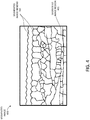
- FIG. 4 illustrates a segmented image 400 that includes segmented image regions 401 resulting from segmenting greyscale image 300.
- Segmentation can include superpixel segmentation, which can estimate consistent regions by grouping pixels into perceptually meaningful regions.
- the pixel groupings can capture image redundancy, provide a convenient primitive from which to compute image features, and reduce the complexity of subsequent image processing tasks.
- a superpixel algorithm by itself, may create over-segmentation or under-segmentation, which may lead to additional color artifacts.
- segmentation can include a modified superpixel segmentation that may mitigate creation of additional artifacts.
- a modified superpixel segmentation can include over-segmenting the image and then merging superpixels that are spatially close and have similar statistics (e.g., similar luminance mean and variance). For example, after a superpixel algorithm is applied, adjacent superpixels S1 and S2 can be merged if: ⁇ S 2 ⁇ ⁇ S 1 2 + ⁇ S 2 ⁇ ⁇ S 1 2 ⁇ T
- ⁇ S 2 , ⁇ S 1 and ⁇ S 2 , ⁇ S 1 are the mean and variance of the considered superpixels, respectively.
- T is a threshold, which can be set to 2.5.
- segmentation can be based on luminance information, for example, luminance components of an input image to be colorized such as grayscale image 300.
- luminance information for example, luminance components of an input image to be colorized such as grayscale image 300.
- segmentation can be based on luminance information of the color image itself, while in other embodiments, segmentation can be based on luminance information of the original grayscale image that was colorized to result in the colorized image (if luminance information of the original grayscale image is obtained).
- the methods of FIG. 2 and FIGS. 3-8 can be applied to grayscale and color images regardless of any previous image processing that the images may have undergone, i.e., independent of any previous image processing.
- the methods may be used in post-processing of images to correct artifacts that can result from previous image processing.
- a morphological skeleton (e.g., a medial axis representation) can be determined (202) for each segmented image region.
- the segmented image regions can provide a basis for determining morphological skeletons.
- the morphological skeletons can be used as starting locations for color in a color diffusion process. Morphological skeletons may provide better color diffusion results in comparison to using other types of strokes or using points for the starting locations.
- morphological skeletons may span the segmented image regions better, such that color can be more evenly diffused throughout the segmented image regions. This may reduce undesirable desaturation that can occur near the edges of the segmented image regions, particularly when a single point within each segmented image region is used as the starting location.
- FIG. 5 is a conceptual illustration 500 showing a segmented image including a morphological skeleton 501 determined for each segmented image region 401.
- a color can be associated (203) with each morphological skeleton.
- each morphological skeleton can be seeded with color.
- the color associated with each morphological skeleton can be based on, for example, an input color image to be re-colored, a color template image, user input, etc.
- the segmented image regions can provide a basis for determining morphological skeletons.
- the segmented image regions also can provide a basis for determining the colors to be associated with the morphological skeletons.
- the color to associate with each morphological skeleton can be determined in a variety of ways.
- the color associated with each morphological skeleton can be based on the color in the segmented image region in the input color image.
- associating color with each morphological skeleton can include determining a most frequent color of the segmented image region in the input color image.
- the color associated with each morphological skeleton can be determined based on a mean color, a median color, etc., of the segmented image region in the input color image.
- Other ways to determine the color to associate with each morphological skeleton can include, for example, clustering the hues in the input color image and assigning a closest hue to each segmented image region, using one or more of various voting schemes, etc., as one skilled in the art will readily understand.
- the color to associate with each morphological skeleton can be determined in a variety of ways.
- the input grayscale image showing the boundaries of the segmented image regions can be displayed to a user, and the user can input a desired color for each segmented image region.
- the desired colors can be associated with the corresponding morphological skeletons.
- a color image may be used as a template for the determining colors associated with morphological skeletons.
- FIG. 6 is a conceptual illustration 600 showing color-seeded morphological skeletons 601, which are obtained by associating color with morphological skeletons 501.
- the confidence values can be compared, and the diffused color with the highest confidence value can be assigned to the pixel.
- a weight can be determined for the diffused color from each morphological skeleton, and the diffused colors can be combined based on the weights to obtain a final color value assigned to the pixel.
- weights and/or confidence levels can be based on factors including, for example, distance from the morphological skeleton, morphological skeleton size, differences between the overlapping diffused colors, etc.
- Other methods of diffusing color may be used, such as methods that take into account texture, boundaries, etc., such as one skilled in the art will readily understand.
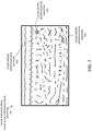
- FIG. 7 is a conceptual illustration 700 showing color diffusion from color-seeded morphological skeletons 601. The color diffusion is illustrated by small arrows extending from the color-seeded morphological skeletons. For the sake of clarity, color diffusion is illustrated for only some of the color-seeded morphological skeletons, but it should be understood that color is diffused from all of the color-seeded morphological skeletons.
- a color image can be obtained (205) based on the diffused color.
- the color image can be the direct result of the color diffusion.
- other processing can be applied to the result of the color diffusion to obtain a final color image.
- Other processing can include, for example, gamma correction, color saturation adjustment, etc.
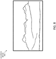
- FIG. 8 is a conceptual illustration of a colorized image 800 of input grayscale image 300 that can result from the color diffusion of color-seeded morphological skeletons 601.
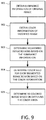
- FIG. 9 is a flowchart of an example of another method according to various embodiments.
- the method may be implemented to re-color a color image, for example, as a post-processing step to help correct visual artifacts that can result from other colorizing or re-coloring processes.
- the method may help reduce or eliminate typical artifacts caused by automatic color image processing/mapping methods, such as color transfer, color harmonization, colorization of greyscale pictures, etc.
- some conventional image processing methods might produce color inconsistency in areas where the color and/or luminance values change smoothly in the original picture.
- some conventional colorization methods can create spatial irregularities, strong artificial color edges, etc., that are not present in the original image.
- the method of FIG. 9 may be viewed as a regularization method that can be implemented as a post-processing for improving the visual quality of any color image processing method.
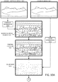
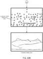
- FIGS. 10A-B show a conceptual illustration of an example of an implementation of the method of FIG. 9 to re-color a colorized image of an original grayscale image.
- FIGS. 10A-B will be referenced in order to illustrate how the method of FIG. 9 can be implemented according to one particular embodiment.
- luminance information of an original image can be obtained (901).
- the luminance information can include, for example, luminance components of the original image, such as values of a luminance channel at each pixel.
- Color information of a modified image can be obtained (902).
- the color information can include, for example, color components of the modified image, such as values of color channels at each pixel.
- the modified image can be an image resulting from image processing of the original image.
- the modified image can be a colorized version of an original grayscale image.
- an original grayscale image 1000 has been colorized, for example using a conventional colorization method, resulting in a colorized image 1001.
- the modified image can be a re-colored version of an original color image.
- Segmented image regions can be determined (903) based on the luminance information of the original image.
- segmentation can include superpixel segmentation.
- superpixel algorithm by itself, may create over-segmentation or under-segmentation, which may lead to additional color artifacts.
- segmentation can include a modified superpixel segmentation, which can include over-segmenting the image and then merging superpixels that are spatially close and have similar statistics (e.g., similar luminance mean and variance). For example, after a superpixel algorithm is applied, adjacent superpixels S1 and S2 can be merged based on Equation (1) above, for example.
- superpixel segmentation is described herein as one method of segmentation, other methods for segmenting images can be implemented, as one skilled in the art will readily understand.
- FIG. 10A shows luminance information 1003 can be obtained from original grayscale image 1000, and segmented image regions 1005 can be determined based on the luminance information.
- a color seed can be determined (904) for each segmented image region based on the color information of the modified image.
- determining a color seed for each segmented image region can include determining a starting location, such as a morphological skeleton, a point, etc., corresponding to the segmented image region and associating color with the morphological skeleton, where the associated color is based on the color information of the modified image.
- Techniques described above with respect to the method of FIG. 2 can be applied, for example, to determine morphological skeletons and seed the morphological skeletons with color, as one skilled in the art will readily understand. Similar techniques can be used to determine points or other shapes as starting locations, and to seed the starting locations with color. For example, each starting location can be determined as a center point of each segmented image region.
- the segmented image regions can provide a basis for determining the colors of the color seeds.
- the color associated with each morphological skeleton, point, etc. can be based on the color of the segmented image region in the modified image, e.g., the colorized image in the example of FIGS. 10A-10B .
- associating color with each morphological skeleton, point, etc. can include determining a most frequent color of the segmented image region in the modified image.
- the color associated with each morphological skeleton, point, etc. can be determined based on a mean color, a median color, etc., of the segmented image region in the modified image.
- a re-colored image can be determined (905) based on diffusing the color seeds.
- color diffusion can be based, for example, on Levin's algorithm, which can take into account the luminance of nearby pixels, such that if the luminance is similar the color is diffused to the nearby pixel, and if the luminance is not similar the color is not diffused.
- the luminance of each pixel can be based on the luminance information, such as luminance components, of pixels in the original image.
- Other methods of diffusing color may be used, such as methods that take into account texture, boundaries, etc., such as one skilled in the art will readily understand.
- Color components can be determined based on diffusing the color seeds, and the re-colored image be determined by combining the color components with the luminance components of the original image.
- color diffusion 1013 from seeds is illustrated by small arrows extending from color seeds 1011.
- Re-colored image 1015 can be determined based on color diffusion 1013.
- the re-colored image can be the direct result of the color diffusion.
- other processing can be applied to the result of the color diffusion to obtain a final re-colored image.
- Other processing can include, for example, gamma correction, color saturation adjustment, etc.
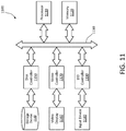
- FIG. 11 illustrates another example of an apparatus according to various embodiments.
- FIG. 11 is a block diagram of an apparatus 1100 for implementing various techniques described above for coloring and re-coloring digital images.
- Apparatus 1100 may be implemented, for example, as a general-purpose computing platform.
- Apparatus 1100 can include a processor 1110 for executing the computer-executable programs that perform various techniques described above.
- the programs may be stored in a memory 1120, which may also store image data.
- a bus 1130 can connect processor 1110 and memory 1120 to each other and to other components of apparatus 1100.
- apparatus 1100 may include multiple processors or processors with multiple processing cores, which may execute various parts of programs in parallel.
- a mass storage device 1140 can be connected to bus 1130 via a disk controller 1150.
- Mass storage device 1140 may contain image or video data, as well as an operating system, other programs, other data, etc.
- Disk controller 1150 may operate according to Serial Advanced Technology Advancement (SATA), Small Computer System Interface (SCSI), or other standards, and may provide connection to multiple mass storage devices.
- SATA Serial Advanced Technology Advancement
- SCSI Small Computer System Interface
- a video display 1160 can be connected to bus 1130 via a video controller 1170.
- Video controller 1170 may provide its own memory and graphics-processing capability for use in implementing or accelerating certain aspects of the colorization, re-colorization, or color correction processes, as well as for providing the functions of image and UI display.
- An input device 1180 can be connected to bus 1130 via an input/output (I/O) controller 1190.
- I/O controller 1190 may utilize one or more of USB, IEEE 1394a, or other standards. Multiple input devices may be connected, such as keyboards, mice, and trackpads. Image and video capture devices may also be connected to the system through I/O controller 1190 or additional I/O controllers implementing other I/O standards. Networking functionality may be provided by I/O controller 1190 or a separate I/O controller.
- frames may be divided among tens or hundreds of computing systems to provide parallel processing.
- Particular components such as video display 1160, may be omitted in some systems in some operating environments.
- multiple systems may utilize shared storage accessed via an I/O bus or via a network.
- apparatus 1100 may be implemented within an image capture device such as a digital still camera or digital video camera. Various techniques disclosed herein may be implemented by apparatus 1100 at the time of image capture to color, re-color, or perform color correction.
- Various embodiments can include a system including a processor and a memory storing instructions configured to cause the processor to obtain luminance information of a first image, obtain color information of a second image, the second image being an image resulting from image processing of the first image, determine a plurality of segmented image regions based on the luminance information of the first image, determine a color seed for each segmented image region based on the color information of the second image, and determine a third image based on diffusing the color seeds of the segmented image regions.
- determining the segmented image regions includes performing superpixel segmentation based on the luminance information of the first image.
- determining the segmented image regions further includes merging two or more superpixels, the superpixels resulting from performing the superpixel segmentation.
- determining the color seed for each segmented image region includes determining a point within the segmented image region and associating color with the point, the associated color being based on the color information of the second image.
- determining the color seed for each segmented image region includes determining a morphological skeleton corresponding to the segmented image region and associating color with the morphological skeleton, the associated color being based on the color information of the second image.
- associating color with the morphological skeleton includes determining a most frequent color of the segmented image region in the second image and associating the most frequent color with the morphological skeleton.
- determining the third image based on diffusing the color seeds includes diffusing the color seeds based on the luminance information.
- the luminance information of the first image includes luminance components of the first image
- determining the third image includes diffusing the color seeds to obtain color components and combining the color components with the luminance components of the first image.
Landscapes
- Engineering & Computer Science (AREA)
- Physics & Mathematics (AREA)
- General Physics & Mathematics (AREA)
- Theoretical Computer Science (AREA)
- Computer Vision & Pattern Recognition (AREA)
- Image Processing (AREA)
Applications Claiming Priority (3)
| Application Number | Priority Date | Filing Date | Title |
|---|---|---|---|
| EP14305889 | 2014-06-12 | ||
| EP14307124.9A EP3038057A1 (en) | 2014-12-22 | 2014-12-22 | Methods and systems for color processing of digital images |
| PCT/EP2015/063087 WO2015189343A1 (en) | 2014-06-12 | 2015-06-11 | Methods and systems for color processing of digital images |
Publications (2)
| Publication Number | Publication Date |
|---|---|
| EP3155593A1 EP3155593A1 (en) | 2017-04-19 |
| EP3155593B1 true EP3155593B1 (en) | 2019-01-02 |
Family
ID=53373477
Family Applications (1)
| Application Number | Title | Priority Date | Filing Date |
|---|---|---|---|
| EP15728008.2A Not-in-force EP3155593B1 (en) | 2014-06-12 | 2015-06-11 | Method and device for color processing of digital images |
Country Status (6)
| Country | Link |
|---|---|
| US (1) | US10204432B2 (ja) |
| EP (1) | EP3155593B1 (ja) |
| JP (1) | JP2017517818A (ja) |
| KR (1) | KR20170017911A (ja) |
| CN (1) | CN106462986A (ja) |
| WO (1) | WO2015189343A1 (ja) |
Families Citing this family (15)
| Publication number | Priority date | Publication date | Assignee | Title |
|---|---|---|---|---|
| US9773155B2 (en) * | 2014-10-14 | 2017-09-26 | Microsoft Technology Licensing, Llc | Depth from time of flight camera |
| EP3185206B1 (en) * | 2015-12-22 | 2018-09-26 | Thomson Licensing | Methods and systems for image processing of digital images |
| JP6810996B2 (ja) * | 2016-06-14 | 2021-01-13 | 大学共同利用機関法人自然科学研究機構 | 質感評価システム |
| CN107038695A (zh) * | 2017-04-20 | 2017-08-11 | 厦门美图之家科技有限公司 | 一种图像融合方法及移动设备 |
| US10242464B1 (en) * | 2017-09-18 | 2019-03-26 | Adobe Systems Incorporated | Diffusion coloring using weighted color points |
| CN110751653B (zh) * | 2018-07-24 | 2024-03-12 | 珠海金山办公软件有限公司 | 一种幻灯片中的图片处理方法和装置 |
| CN110216082B (zh) * | 2019-05-23 | 2020-07-14 | 上海交通大学 | 荧光标记种子动态识别方法和系统 |
| KR102652117B1 (ko) * | 2019-07-10 | 2024-03-27 | 삼성전자주식회사 | 이미지 보정 방법 및 이미지 보정 시스템 |
| KR20210053052A (ko) * | 2019-11-01 | 2021-05-11 | 엘지전자 주식회사 | 컬러 복원방법 및 장치 |
| KR102342526B1 (ko) * | 2020-02-27 | 2021-12-23 | 에스케이텔레콤 주식회사 | 비디오 컬러화 방법 및 장치 |
| US10997752B1 (en) * | 2020-03-09 | 2021-05-04 | Adobe Inc. | Utilizing a colorization neural network to generate colorized images based on interactive color edges |
| US11341759B2 (en) * | 2020-03-31 | 2022-05-24 | Capital One Services, Llc | Image classification using color profiles |
| US20230419673A1 (en) * | 2020-10-28 | 2023-12-28 | Creative Semiconductor Ltd. | Deep learning-based wireless camera system with color night vision |
| CN114422698B (zh) * | 2022-01-19 | 2023-09-26 | 北京字跳网络技术有限公司 | 视频生成方法、装置、设备及存储介质 |
| CN117635615A (zh) * | 2024-01-26 | 2024-03-01 | 深圳市常丰激光刀模有限公司 | 基于深度学习实现冲孔模具的缺陷检测方法及系统 |
Family Cites Families (15)
| Publication number | Priority date | Publication date | Assignee | Title |
|---|---|---|---|---|
| US5418895A (en) * | 1992-11-25 | 1995-05-23 | Eastman Kodak Company | Method for displaying a high quality digital color image on a limited color display |
| JP3985679B2 (ja) * | 2001-01-25 | 2007-10-03 | 株式会社ニコン | 画像処理方法、画像処理プログラム、画像処理装置 |
| US8769395B2 (en) * | 2002-12-13 | 2014-07-01 | Ricoh Co., Ltd. | Layout objects as image layers |
| IES20060564A2 (en) * | 2006-05-03 | 2006-11-01 | Fotonation Vision Ltd | Improved foreground / background separation |
| US20080005656A1 (en) * | 2006-06-28 | 2008-01-03 | Shu Fan Stephen Pang | Apparatus, method, and file format for text with synchronized audio |
| US8270709B2 (en) * | 2006-08-31 | 2012-09-18 | Corel Corporation | Color selection and/or matching in a color image |
| FR2918830B1 (fr) | 2007-07-13 | 2009-10-30 | Viaccess Sa | Verification de code mac sans revelation. |
| US8655919B2 (en) | 2007-07-30 | 2014-02-18 | International Business Machines Corporation | Storage system and method for updating a hash tree |
| US8280171B2 (en) * | 2008-05-28 | 2012-10-02 | Apple Inc. | Tools for selecting a section of interest within an image |
| WO2010014067A1 (en) * | 2008-07-31 | 2010-02-04 | Hewlett-Packard Development Company, L.P. | Perceptual segmentation of images |
| US8059892B1 (en) * | 2008-10-01 | 2011-11-15 | Hewlett-Packard Development Company, L.P. | Image enhancement method and apparatus |
| CN101571419B (zh) * | 2009-06-15 | 2010-12-01 | 浙江大学 | 采用图像分割的汽车仪表led指示灯自动检验方法 |
| CN102446250A (zh) * | 2010-10-13 | 2012-05-09 | 索尼公司 | 数据完整性的保护和验证方法、设备和系统 |
| CN102254326A (zh) * | 2011-07-22 | 2011-11-23 | 西安电子科技大学 | 利用核传递进行图像分割的方法 |
| US9547908B1 (en) * | 2015-09-28 | 2017-01-17 | Google Inc. | Feature mask determination for images |
-
2015
- 2015-06-11 KR KR1020167034626A patent/KR20170017911A/ko unknown
- 2015-06-11 US US15/318,165 patent/US10204432B2/en not_active Expired - Fee Related
- 2015-06-11 WO PCT/EP2015/063087 patent/WO2015189343A1/en active Application Filing
- 2015-06-11 JP JP2016571388A patent/JP2017517818A/ja not_active Withdrawn
- 2015-06-11 EP EP15728008.2A patent/EP3155593B1/en not_active Not-in-force
- 2015-06-11 CN CN201580031092.2A patent/CN106462986A/zh active Pending
Non-Patent Citations (1)
| Title |
|---|
| None * |
Also Published As
| Publication number | Publication date |
|---|---|
| CN106462986A (zh) | 2017-02-22 |
| KR20170017911A (ko) | 2017-02-15 |
| WO2015189343A1 (en) | 2015-12-17 |
| EP3155593A1 (en) | 2017-04-19 |
| JP2017517818A (ja) | 2017-06-29 |
| US20170116765A1 (en) | 2017-04-27 |
| US10204432B2 (en) | 2019-02-12 |
Similar Documents
| Publication | Publication Date | Title |
|---|---|---|
| EP3155593B1 (en) | Method and device for color processing of digital images | |
| EP3477931B1 (en) | Image processing method and device, readable storage medium and electronic device | |
| US10997696B2 (en) | Image processing method, apparatus and device | |
| EP3937481A1 (en) | Image display method and device | |
| US20180255254A1 (en) | Automatic lens flare detection and correction for light-field images | |
| US10805508B2 (en) | Image processing method, and device | |
| US10477128B2 (en) | Neighborhood haze density estimation for single-image dehaze | |
| EP3644599B1 (en) | Video processing method and apparatus, electronic device, and storage medium | |
| EP3086553A1 (en) | Method and apparatus for image colorization | |
| US11922598B2 (en) | Image processing apparatus, image processing method, and storage medium | |
| KR102192016B1 (ko) | 의미 인식 기반의 이미지 보정 방법 및 그를 위한 장치 | |
| US10268881B2 (en) | Pattern classifying apparatus, information processing apparatus, pattern classifying method, and non-transitory computer readable storage medium | |
| EP3038057A1 (en) | Methods and systems for color processing of digital images | |
| US20170372495A1 (en) | Methods and systems for color processing of digital images | |
| WO2015189369A1 (en) | Methods and systems for color processing of digital images | |
| JP6963038B2 (ja) | 画像処理装置および画像処理方法 | |
| KR101592087B1 (ko) | 배경 영상의 위치를 이용한 관심맵 생성 방법 및 이를 기록한 기록 매체 | |
| EP3038059A1 (en) | Methods and systems for color processing of digital images | |
| US11244187B2 (en) | Information processing apparatus and non-transitory computer readable medium | |
| US20220408013A1 (en) | DNN Assisted Object Detection and Image Optimization | |
| CN115641261A (zh) | 一种红外图像的处理方法、装置、介质以及红外热像仪 | |
| RU2509366C1 (ru) | Система и способ преобразования тонов плоских и объемных изображений |
Legal Events
| Date | Code | Title | Description |
|---|---|---|---|
| STAA | Information on the status of an ep patent application or granted ep patent |
Free format text: STATUS: THE INTERNATIONAL PUBLICATION HAS BEEN MADE |
|
| PUAI | Public reference made under article 153(3) epc to a published international application that has entered the european phase |
Free format text: ORIGINAL CODE: 0009012 |
|
| STAA | Information on the status of an ep patent application or granted ep patent |
Free format text: STATUS: REQUEST FOR EXAMINATION WAS MADE |
|
| 17P | Request for examination filed |
Effective date: 20161214 |
|
| AK | Designated contracting states |
Kind code of ref document: A1 Designated state(s): AL AT BE BG CH CY CZ DE DK EE ES FI FR GB GR HR HU IE IS IT LI LT LU LV MC MK MT NL NO PL PT RO RS SE SI SK SM TR |
|
| AX | Request for extension of the european patent |
Extension state: BA ME |
|
| DAV | Request for validation of the european patent (deleted) | ||
| DAX | Request for extension of the european patent (deleted) | ||
| GRAP | Despatch of communication of intention to grant a patent |
Free format text: ORIGINAL CODE: EPIDOSNIGR1 |
|
| STAA | Information on the status of an ep patent application or granted ep patent |
Free format text: STATUS: GRANT OF PATENT IS INTENDED |
|
| INTG | Intention to grant announced |
Effective date: 20180731 |
|
| GRAS | Grant fee paid |
Free format text: ORIGINAL CODE: EPIDOSNIGR3 |
|
| GRAA | (expected) grant |
Free format text: ORIGINAL CODE: 0009210 |
|
| STAA | Information on the status of an ep patent application or granted ep patent |
Free format text: STATUS: THE PATENT HAS BEEN GRANTED |
|
| AK | Designated contracting states |
Kind code of ref document: B1 Designated state(s): AL AT BE BG CH CY CZ DE DK EE ES FI FR GB GR HR HU IE IS IT LI LT LU LV MC MK MT NL NO PL PT RO RS SE SI SK SM TR |
|
| REG | Reference to a national code |
Ref country code: GB Ref legal event code: FG4D |
|
| REG | Reference to a national code |
Ref country code: CH Ref legal event code: EP Ref country code: AT Ref legal event code: REF Ref document number: 1085337 Country of ref document: AT Kind code of ref document: T Effective date: 20190115 |
|
| REG | Reference to a national code |
Ref country code: IE Ref legal event code: FG4D |
|
| REG | Reference to a national code |
Ref country code: DE Ref legal event code: R096 Ref document number: 602015022765 Country of ref document: DE |
|
| REG | Reference to a national code |
Ref country code: NL Ref legal event code: FP |
|
| REG | Reference to a national code |
Ref country code: LT Ref legal event code: MG4D |
|
| REG | Reference to a national code |
Ref country code: AT Ref legal event code: MK05 Ref document number: 1085337 Country of ref document: AT Kind code of ref document: T Effective date: 20190102 |
|
| PG25 | Lapsed in a contracting state [announced via postgrant information from national office to epo] |
Ref country code: PL Free format text: LAPSE BECAUSE OF FAILURE TO SUBMIT A TRANSLATION OF THE DESCRIPTION OR TO PAY THE FEE WITHIN THE PRESCRIBED TIME-LIMIT Effective date: 20190102 Ref country code: FI Free format text: LAPSE BECAUSE OF FAILURE TO SUBMIT A TRANSLATION OF THE DESCRIPTION OR TO PAY THE FEE WITHIN THE PRESCRIBED TIME-LIMIT Effective date: 20190102 Ref country code: LT Free format text: LAPSE BECAUSE OF FAILURE TO SUBMIT A TRANSLATION OF THE DESCRIPTION OR TO PAY THE FEE WITHIN THE PRESCRIBED TIME-LIMIT Effective date: 20190102 Ref country code: SE Free format text: LAPSE BECAUSE OF FAILURE TO SUBMIT A TRANSLATION OF THE DESCRIPTION OR TO PAY THE FEE WITHIN THE PRESCRIBED TIME-LIMIT Effective date: 20190102 Ref country code: NO Free format text: LAPSE BECAUSE OF FAILURE TO SUBMIT A TRANSLATION OF THE DESCRIPTION OR TO PAY THE FEE WITHIN THE PRESCRIBED TIME-LIMIT Effective date: 20190402 Ref country code: PT Free format text: LAPSE BECAUSE OF FAILURE TO SUBMIT A TRANSLATION OF THE DESCRIPTION OR TO PAY THE FEE WITHIN THE PRESCRIBED TIME-LIMIT Effective date: 20190502 Ref country code: ES Free format text: LAPSE BECAUSE OF FAILURE TO SUBMIT A TRANSLATION OF THE DESCRIPTION OR TO PAY THE FEE WITHIN THE PRESCRIBED TIME-LIMIT Effective date: 20190102 |
|
| PG25 | Lapsed in a contracting state [announced via postgrant information from national office to epo] |
Ref country code: GR Free format text: LAPSE BECAUSE OF FAILURE TO SUBMIT A TRANSLATION OF THE DESCRIPTION OR TO PAY THE FEE WITHIN THE PRESCRIBED TIME-LIMIT Effective date: 20190403 Ref country code: RS Free format text: LAPSE BECAUSE OF FAILURE TO SUBMIT A TRANSLATION OF THE DESCRIPTION OR TO PAY THE FEE WITHIN THE PRESCRIBED TIME-LIMIT Effective date: 20190102 Ref country code: BG Free format text: LAPSE BECAUSE OF FAILURE TO SUBMIT A TRANSLATION OF THE DESCRIPTION OR TO PAY THE FEE WITHIN THE PRESCRIBED TIME-LIMIT Effective date: 20190402 Ref country code: IS Free format text: LAPSE BECAUSE OF FAILURE TO SUBMIT A TRANSLATION OF THE DESCRIPTION OR TO PAY THE FEE WITHIN THE PRESCRIBED TIME-LIMIT Effective date: 20190502 Ref country code: HR Free format text: LAPSE BECAUSE OF FAILURE TO SUBMIT A TRANSLATION OF THE DESCRIPTION OR TO PAY THE FEE WITHIN THE PRESCRIBED TIME-LIMIT Effective date: 20190102 Ref country code: LV Free format text: LAPSE BECAUSE OF FAILURE TO SUBMIT A TRANSLATION OF THE DESCRIPTION OR TO PAY THE FEE WITHIN THE PRESCRIBED TIME-LIMIT Effective date: 20190102 |
|
| REG | Reference to a national code |
Ref country code: DE Ref legal event code: R097 Ref document number: 602015022765 Country of ref document: DE |
|
| REG | Reference to a national code |
Ref country code: GB Ref legal event code: 732E Free format text: REGISTERED BETWEEN 20190926 AND 20191002 |
|
| PG25 | Lapsed in a contracting state [announced via postgrant information from national office to epo] |
Ref country code: AL Free format text: LAPSE BECAUSE OF FAILURE TO SUBMIT A TRANSLATION OF THE DESCRIPTION OR TO PAY THE FEE WITHIN THE PRESCRIBED TIME-LIMIT Effective date: 20190102 Ref country code: AT Free format text: LAPSE BECAUSE OF FAILURE TO SUBMIT A TRANSLATION OF THE DESCRIPTION OR TO PAY THE FEE WITHIN THE PRESCRIBED TIME-LIMIT Effective date: 20190102 Ref country code: EE Free format text: LAPSE BECAUSE OF FAILURE TO SUBMIT A TRANSLATION OF THE DESCRIPTION OR TO PAY THE FEE WITHIN THE PRESCRIBED TIME-LIMIT Effective date: 20190102 Ref country code: IT Free format text: LAPSE BECAUSE OF FAILURE TO SUBMIT A TRANSLATION OF THE DESCRIPTION OR TO PAY THE FEE WITHIN THE PRESCRIBED TIME-LIMIT Effective date: 20190102 Ref country code: DK Free format text: LAPSE BECAUSE OF FAILURE TO SUBMIT A TRANSLATION OF THE DESCRIPTION OR TO PAY THE FEE WITHIN THE PRESCRIBED TIME-LIMIT Effective date: 20190102 Ref country code: RO Free format text: LAPSE BECAUSE OF FAILURE TO SUBMIT A TRANSLATION OF THE DESCRIPTION OR TO PAY THE FEE WITHIN THE PRESCRIBED TIME-LIMIT Effective date: 20190102 Ref country code: SK Free format text: LAPSE BECAUSE OF FAILURE TO SUBMIT A TRANSLATION OF THE DESCRIPTION OR TO PAY THE FEE WITHIN THE PRESCRIBED TIME-LIMIT Effective date: 20190102 Ref country code: CZ Free format text: LAPSE BECAUSE OF FAILURE TO SUBMIT A TRANSLATION OF THE DESCRIPTION OR TO PAY THE FEE WITHIN THE PRESCRIBED TIME-LIMIT Effective date: 20190102 |
|
| PLBE | No opposition filed within time limit |
Free format text: ORIGINAL CODE: 0009261 |
|
| STAA | Information on the status of an ep patent application or granted ep patent |
Free format text: STATUS: NO OPPOSITION FILED WITHIN TIME LIMIT |
|
| PG25 | Lapsed in a contracting state [announced via postgrant information from national office to epo] |
Ref country code: SM Free format text: LAPSE BECAUSE OF FAILURE TO SUBMIT A TRANSLATION OF THE DESCRIPTION OR TO PAY THE FEE WITHIN THE PRESCRIBED TIME-LIMIT Effective date: 20190102 |
|
| 26N | No opposition filed |
Effective date: 20191003 |
|
| PG25 | Lapsed in a contracting state [announced via postgrant information from national office to epo] |
Ref country code: MC Free format text: LAPSE BECAUSE OF FAILURE TO SUBMIT A TRANSLATION OF THE DESCRIPTION OR TO PAY THE FEE WITHIN THE PRESCRIBED TIME-LIMIT Effective date: 20190102 |
|
| REG | Reference to a national code |
Ref country code: CH Ref legal event code: PL |
|
| PG25 | Lapsed in a contracting state [announced via postgrant information from national office to epo] |
Ref country code: SI Free format text: LAPSE BECAUSE OF FAILURE TO SUBMIT A TRANSLATION OF THE DESCRIPTION OR TO PAY THE FEE WITHIN THE PRESCRIBED TIME-LIMIT Effective date: 20190102 |
|
| REG | Reference to a national code |
Ref country code: BE Ref legal event code: MM Effective date: 20190630 |
|
| PG25 | Lapsed in a contracting state [announced via postgrant information from national office to epo] |
Ref country code: TR Free format text: LAPSE BECAUSE OF FAILURE TO SUBMIT A TRANSLATION OF THE DESCRIPTION OR TO PAY THE FEE WITHIN THE PRESCRIBED TIME-LIMIT Effective date: 20190102 |
|
| PG25 | Lapsed in a contracting state [announced via postgrant information from national office to epo] |
Ref country code: IE Free format text: LAPSE BECAUSE OF NON-PAYMENT OF DUE FEES Effective date: 20190611 |
|
| PG25 | Lapsed in a contracting state [announced via postgrant information from national office to epo] |
Ref country code: LI Free format text: LAPSE BECAUSE OF NON-PAYMENT OF DUE FEES Effective date: 20190630 Ref country code: CH Free format text: LAPSE BECAUSE OF NON-PAYMENT OF DUE FEES Effective date: 20190630 Ref country code: BE Free format text: LAPSE BECAUSE OF NON-PAYMENT OF DUE FEES Effective date: 20190630 Ref country code: LU Free format text: LAPSE BECAUSE OF NON-PAYMENT OF DUE FEES Effective date: 20190611 |
|
| PGFP | Annual fee paid to national office [announced via postgrant information from national office to epo] |
Ref country code: FR Payment date: 20200626 Year of fee payment: 6 |
|
| PGFP | Annual fee paid to national office [announced via postgrant information from national office to epo] |
Ref country code: NL Payment date: 20200625 Year of fee payment: 6 Ref country code: GB Payment date: 20200630 Year of fee payment: 6 |
|
| PGFP | Annual fee paid to national office [announced via postgrant information from national office to epo] |
Ref country code: DE Payment date: 20200630 Year of fee payment: 6 |
|
| PG25 | Lapsed in a contracting state [announced via postgrant information from national office to epo] |
Ref country code: CY Free format text: LAPSE BECAUSE OF FAILURE TO SUBMIT A TRANSLATION OF THE DESCRIPTION OR TO PAY THE FEE WITHIN THE PRESCRIBED TIME-LIMIT Effective date: 20190102 |
|
| PG25 | Lapsed in a contracting state [announced via postgrant information from national office to epo] |
Ref country code: HU Free format text: LAPSE BECAUSE OF FAILURE TO SUBMIT A TRANSLATION OF THE DESCRIPTION OR TO PAY THE FEE WITHIN THE PRESCRIBED TIME-LIMIT; INVALID AB INITIO Effective date: 20150611 Ref country code: MT Free format text: LAPSE BECAUSE OF FAILURE TO SUBMIT A TRANSLATION OF THE DESCRIPTION OR TO PAY THE FEE WITHIN THE PRESCRIBED TIME-LIMIT Effective date: 20190102 |
|
| REG | Reference to a national code |
Ref country code: DE Ref legal event code: R119 Ref document number: 602015022765 Country of ref document: DE |
|
| REG | Reference to a national code |
Ref country code: NL Ref legal event code: MM Effective date: 20210701 |
|
| GBPC | Gb: european patent ceased through non-payment of renewal fee |
Effective date: 20210611 |
|
| PG25 | Lapsed in a contracting state [announced via postgrant information from national office to epo] |
Ref country code: GB Free format text: LAPSE BECAUSE OF NON-PAYMENT OF DUE FEES Effective date: 20210611 Ref country code: DE Free format text: LAPSE BECAUSE OF NON-PAYMENT OF DUE FEES Effective date: 20220101 |
|
| PG25 | Lapsed in a contracting state [announced via postgrant information from national office to epo] |
Ref country code: NL Free format text: LAPSE BECAUSE OF NON-PAYMENT OF DUE FEES Effective date: 20210701 Ref country code: FR Free format text: LAPSE BECAUSE OF NON-PAYMENT OF DUE FEES Effective date: 20210630 |
|
| PG25 | Lapsed in a contracting state [announced via postgrant information from national office to epo] |
Ref country code: MK Free format text: LAPSE BECAUSE OF FAILURE TO SUBMIT A TRANSLATION OF THE DESCRIPTION OR TO PAY THE FEE WITHIN THE PRESCRIBED TIME-LIMIT Effective date: 20190102 |