EP3155504B1 - Verfahren, computerprogrammprodukt und vorrichtung zur ortung von interaktion auf einer berührungsempfindlichen oberfläche - Google Patents
Verfahren, computerprogrammprodukt und vorrichtung zur ortung von interaktion auf einer berührungsempfindlichen oberfläche Download PDFInfo
- Publication number
- EP3155504B1 EP3155504B1 EP15727660.1A EP15727660A EP3155504B1 EP 3155504 B1 EP3155504 B1 EP 3155504B1 EP 15727660 A EP15727660 A EP 15727660A EP 3155504 B1 EP3155504 B1 EP 3155504B1
- Authority
- EP
- European Patent Office
- Prior art keywords
- sensors
- interaction
- sensor
- value
- calculating
- Prior art date
- Legal status (The legal status is an assumption and is not a legal conclusion. Google has not performed a legal analysis and makes no representation as to the accuracy of the status listed.)
- Not-in-force
Links
Images



Classifications
-
- G—PHYSICS
- G06—COMPUTING OR CALCULATING; COUNTING
- G06F—ELECTRIC DIGITAL DATA PROCESSING
- G06F1/00—Details not covered by groups G06F3/00 - G06F13/00 and G06F21/00
- G06F1/16—Constructional details or arrangements
- G06F1/1601—Constructional details related to the housing of computer displays, e.g. of CRT monitors, of flat displays
-
- G—PHYSICS
- G06—COMPUTING OR CALCULATING; COUNTING
- G06F—ELECTRIC DIGITAL DATA PROCESSING
- G06F3/00—Input arrangements for transferring data to be processed into a form capable of being handled by the computer; Output arrangements for transferring data from processing unit to output unit, e.g. interface arrangements
- G06F3/01—Input arrangements or combined input and output arrangements for interaction between user and computer
- G06F3/03—Arrangements for converting the position or the displacement of a member into a coded form
- G06F3/041—Digitisers, e.g. for touch screens or touch pads, characterised by the transducing means
- G06F3/0414—Digitisers, e.g. for touch screens or touch pads, characterised by the transducing means using force sensing means to determine a position
-
- G—PHYSICS
- G06—COMPUTING OR CALCULATING; COUNTING
- G06F—ELECTRIC DIGITAL DATA PROCESSING
- G06F3/00—Input arrangements for transferring data to be processed into a form capable of being handled by the computer; Output arrangements for transferring data from processing unit to output unit, e.g. interface arrangements
- G06F3/01—Input arrangements or combined input and output arrangements for interaction between user and computer
- G06F3/03—Arrangements for converting the position or the displacement of a member into a coded form
- G06F3/041—Digitisers, e.g. for touch screens or touch pads, characterised by the transducing means
- G06F3/044—Digitisers, e.g. for touch screens or touch pads, characterised by the transducing means by capacitive means
-
- G—PHYSICS
- G06—COMPUTING OR CALCULATING; COUNTING
- G06F—ELECTRIC DIGITAL DATA PROCESSING
- G06F3/00—Input arrangements for transferring data to be processed into a form capable of being handled by the computer; Output arrangements for transferring data from processing unit to output unit, e.g. interface arrangements
- G06F3/01—Input arrangements or combined input and output arrangements for interaction between user and computer
- G06F3/03—Arrangements for converting the position or the displacement of a member into a coded form
- G06F3/041—Digitisers, e.g. for touch screens or touch pads, characterised by the transducing means
- G06F3/044—Digitisers, e.g. for touch screens or touch pads, characterised by the transducing means by capacitive means
- G06F3/0447—Position sensing using the local deformation of sensor cells
-
- H—ELECTRICITY
- H03—ELECTRONIC CIRCUITRY
- H03K—PULSE TECHNIQUE
- H03K17/00—Electronic switching or gating, i.e. not by contact-making and –breaking
- H03K17/94—Electronic switching or gating, i.e. not by contact-making and –breaking characterised by the way in which the control signals are generated
- H03K17/965—Switches controlled by moving an element forming part of the switch
- H03K17/975—Switches controlled by moving an element forming part of the switch using a capacitive movable element
-
- H—ELECTRICITY
- H03—ELECTRONIC CIRCUITRY
- H03K—PULSE TECHNIQUE
- H03K17/00—Electronic switching or gating, i.e. not by contact-making and –breaking
- H03K17/94—Electronic switching or gating, i.e. not by contact-making and –breaking characterised by the way in which the control signals are generated
- H03K17/96—Touch switches
- H03K17/962—Capacitive touch switches
-
- H—ELECTRICITY
- H03—ELECTRONIC CIRCUITRY
- H03K—PULSE TECHNIQUE
- H03K2217/00—Indexing scheme related to electronic switching or gating, i.e. not by contact-making or -breaking covered by H03K17/00
- H03K2217/94—Indexing scheme related to electronic switching or gating, i.e. not by contact-making or -breaking covered by H03K17/00 characterised by the way in which the control signal is generated
- H03K2217/96—Touch switches
- H03K2217/9607—Capacitive touch switches
- H03K2217/960755—Constructional details of capacitive touch and proximity switches
Definitions
- the invention is in the field of tactile surfaces and more particularly relates to a method for locating an interaction on a tactile surface.
- the known solutions mainly concern two approaches, which are the deployment of a capacitive film or the laying of an infrared frame on the surface. .
- a film composed of an electrical network etched on it and connected to electronics is deployed and glued on the surface to be touched.
- the capacity that is measured is changed, to locate the interaction.
- the disadvantage of this approach is that it is not compatible with any other element than the finger, making it difficult, for example, to wear gloves.
- the deployment of such a film makes visible a network of son printed on it decreasing the transparency of the surface.
- Infrared (IR) -based solutions use a frame of infrared light emitting diodes (LEDs) placed on the surface and forming a grid of transmitting and receiving rows. When a finger or other object cuts the horizontal and vertical beams, it is localized. This technology is very sensitive to sunlight which is very charged in infrared, as well as to the environment such as the level of dirt on the surface.
- the infrared frame in general has the appearance of a bowl, which is a brake in the general design and the use of various surfaces.
- the interaction point is determined by considering the distribution of forces and associating it with the barycentre of the sensors weighted by the respective pressures measured.
- the patent US3657475 proposes a device using three sensors to determine the pressure point on a plate.
- the patent application US 2003/0079549 A1 presents a method to locate the pressure points on a touch surface that is based on the addition of a flexible membrane on the touch surface and sensors to determine the pressure points on the membrane.
- transition to larger surfaces causes problems with the rigidity of the plate and the deformation of the surface under the application of an interaction force.
- the present invention addresses this need by overcoming the disadvantages of existing approaches.
- An object of the present invention is to provide a device and method for locating an interaction of a large surface whose rigidity is not infinite.
- the device of the invention allows a large surface to be tactilized in a completely transparent manner.
- Another object of the present invention is to provide a process for the tactileization of a surface that offers easy implementation and a reduced cost of implementation.
- Another object of the present invention is to provide a modular tactile device for easily adding or removing sensors.
- Another object of the invention is to propose a device which makes it possible to limit the deformation of the surface to be touched by allowing it to be fixed on a built-in frame.
- the invention proposes a method based on the measurement of force and the fusion of information from several sensors to locate an interaction on a surface to be touched.
- the present invention will apply advantageously for large interactive terminals, furniture to be touched, or any application called “simple touch” currently implemented with infrared and capacitive devices.
- a typical application may be the touching of a large ceiling lamp in the passenger compartment of an automobile.
- the method and apparatus of the present invention allows total or partial lighting of the ceiling lamp via localized tactile interaction.
- the proposed device does not alter the transparency of the ceiling, and is particularly well suited to let the light.
- steps (a) and (b) are applied for each Y Y axis coordinate and for a plurality of discrete positions 'Lj' and step (c) determines the discrete position 'Lj' closest to the interaction on the Y axis.
- the method comprises after the calculation step (a), a step of normalizing the values of each equivalent sensor with respect to reference sensor model values.
- the step of calculating the individual cost consists in calculating the value squared of the difference between the normalized value of the sensor equivalent and a normalized value that said equivalent sensor would measure at said discrete position 'Li'.
- the method comprises a preliminary calibration step for defining the normalized value.
- the method comprises, after the determining step (c), a step of filtering the determined positions.
- the filtering is done with a low pass filter.
- the filter frequency is defined according to adjustable thresholds.
- the method of the invention may include a preliminary step of determining an interaction on the surface.
- the determining step may include measuring a weight on the surface and determining whether the measured weight is greater than a threshold value.
- a static bias value is deducted from the measurement of the weight exerted.
- the invention also relates to a device for locating an interaction on a surface equipped with a plurality of sensors positioned along axes (X, Y) at coordinates (Xi, Yj), each sensor being able to provide a value representative of the measured effort during an interaction, the device comprising means for implementing the steps of the process.
- the surface may be embedded in a fixed frame and the plurality of sensors may comprise sensors placed between the surface and the frame.
- the plurality of sensors may comprise planar capacitive sensors positioned below the surface.
- the plurality of sensors may comprise forensic capacitive sensors, each fork capacitive sensor comprising two planar capacitive sensors assembled into a unitary capacitive device and positioned respectively opposite and under said surface.
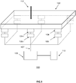
- the figure 1 illustrates a device 100 for operating the method of the invention in one embodiment.
- a surface 102 is equipped with a plurality of sensors 104-i.
- the figure 1 shows six sensors placed under a rectangular surface, but the skilled person can extend the principles of the invention to any other sensor configuration and other surface form also surface relief (3D).
- the surface may be a flexible polycarbonate sheet or a transparent polymethyl methacrylate (PMMA) thermoplastic sheet or be made of any wood, plastic or glass material.
- PMMA polymethyl methacrylate
- the surface may be embedded in a support, a frame or a fixed frame not shown on the figure 1 , and the sensors placed between the surface and the frame.
- the sensors are a capacitive fork device as described with reference to FIG. figure 2 .
- each sensor 104 is locally coupled to a local force measurement module 106 making it possible to measure the force passing through the sensor during an interaction 112 on the surface.
- the effort measurement module contains analog / digital conversion means that can have a regulation or filtering system of the power supply.
- each local effort measurement module 106 is sent to an interaction location module 108 via a transmission bus of half-duplex bidirectional synchronous serial data bus type data, such as the standardized I2C bus for example.
- the buses 107 providing the link between the location module and each of the force measuring modules of each sensor are shielded son.
- the local effort measurement modules 106-i are coupled to an interaction localization module 108 capable of operating the localization method of the invention as described below with reference to the Figures 4 to 6 .
- the interaction location module 108 comprises a multiplexer making it possible to receive the data coming from the plurality of the effort measurement modules 106-i, a microcontroller-type processing unit making it possible to execute the localization method interaction of the invention, and various components for filtering and powering functions.
- a connector including power supplies, I2C bus and I / Os can come connect an extension.
- the microcontroller generally comprises at least one processor, random access memory (RAM) and non-volatile memory (FLASH) for storing and executing the interaction localization method of the invention.
- RAM random access memory
- FLASH non-volatile memory
- a second interaction location module can operate in 'slave' mode with a first master module making it possible to distribute the data acquisition of the sensors on both modules.
- a type I2C link establishes the communication between the two modules.
- the modular electronic arrangement combining the local force measurement modules 106-i and the interaction localization module 108 makes it easy to add or remove 104-i sensors in order to adapt to any form of surface and any type of application.
- the interaction location module 108 may be coupled to different devices 110 for interpreting a product result to trigger an action related to the detection of the interaction.
- the module can for example be connected to a computer via a USB output.
- an action can be a response depending on the position of an interaction, such as, for example, the lighting of an LED or a strip of LEDs of a car ceiling lamp depending on the side on which support was exercised by a user.
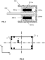
- the figure 2 illustrated an example of a fork sensor in a preferred implementation of the invention.
- the fork sensor consists of two capacitive sensors assembled into a unitary capacitive device, comprising a central armature (208-a, 208-b) integral with the surface to be touched 202 and connected to the ground, two external armatures (210- a, 210-b) respectively connected to an input of the local force measurement module 106, the armatures external members being respectively separated from the central armature by a dielectric material (206-a, 206-b).
- the capacitive sensors are respectively located on either side of a plate 202 having an upper face and a lower face.
- the sensor located above the plate is called 'upper sensor' and the sensor located below the plate is called 'lower sensor'.
- the sensors are arranged on the edges of the plate and embedded in a frame or frame 204. Each sensor comprises two electrodes separated by a dielectric (206-a, 206-b).
- the upper sensor comprises a first electrode 208-a secured to the plate and a second electrode 210-a secured to the frame.
- a dielectric 206-a consisting of an elastic and insulating material, such as silicone or polyurethane, is located between the two electrodes.
- the dielectric makes it possible to increase the measured capacitance by increasing the permittivity of the medium.
- it is a booster function which, when a force related to an interaction is applied to the surface, compresses to bring the two electrodes together, and which, when the force disappears, relaxes in order to restore the electrodes. in their initial rest position.
- the lower sensor comprises a first 208-b electrode integral with the plate and a second 210-b electrode integral with the chassis, separated by a dielectric 206-b.
- Each electrode integral with the plate is movable under the effect of pressure on the plate and the deformation of the dielectric.
- Each fixed electrode of the frame is fixed and constitutes a signal electrode connected respectively to an input of the local force measurement module 106.
- the signal electrode (210-a, 210-b) consists of a cylindrical plate covered with copper on each of its faces.
- a first face is connected to a conversion component of the local force measurement module 106.
- the conversion component makes it possible to digitally convert the capacitance measured at the terminals of the sensor.
- the second face of the signal electrode is connected to a shield to prevent interference.
- a second rectangular shaped plate allows to isolate the shield of the metal frame to avoid short circuits and pass the shielded wire connecting all the measuring modules of effort local to the location module 108.
- the movable electrode consists of an epoxy plate bonded to the ground and bonded to the surface 202 by an adhesive film which may be of the order of 0.1 mm thick.
- an adhesive film which may be of the order of 0.1 mm thick.
- the rigidity of the plate is important and can lead to a deflection angle of the ground electrode which deteriorates the measurement.
- a very flexible layer such as foam can be inserted between the surface 202 and the center frame (208-a, 208-b) to compensate for the deflection angle when the plate deforms.
- the surface is an ice of 90 cm in length, 3 mm thick, equipped with six fork sensors whose electrodes have an area of about 1 cm 2 .
- the signal electrode has a thickness of 1.6mm
- the ground electrode has a thickness of 0.4mm
- the dielectric inserted between the two electrodes is a polyethylene foam 0.8mm thick.
- the fork sensor makes it possible to combine the effect of a plane capacitor operating in compression, when a force is applied to the surface and the lower sensor crushes, and of a second plane capacitor operating in traction when a force is applied to the surface and the upper sensor expands.
- the assembled fork sensor is of better quality than two sensors taken in isolation by an increase in the dynamics of the measurement, a better filtering of the disturbances, and a better compromise on the accuracy of the measurement.
- the fusion of the lower and upper sensors is performed at the level of the local force measurement module 106 connecting the higher capacity on the positive terminal and the lower capacity on the negative terminal and calculating the sum of the capacitances measured on each sensor.
- the fork sensor advantageously allows the embedding in a frame and the maintenance of a surface to be touched without the need to add additional fastening means.
- the patent application of the same applicant entitled “Touch surface maintenance device” filed the same day describes such a holding device based on fork sensor.
- the interaction localization method of the invention can be operated for a capacitive device having only one lower sensor walking in compression.
- the figure 3 illustrates the relationship between an interaction point on a surface and the position of sensors for a large surface equipped with N sensors.
- the sensors are respectively located at a position Pos (n) of the plate, where n represents the number of a sensor between 1 and N.
- the sensors are positioned relative to main axes (X, Y).
- the general principle of the method 400 of locating an interaction as described with reference to the figure 4 is based on the modeling of sensor load distributions and the minimization of a cost associated with the proximity of sensor measurements with reference models that are established by moving a reference mass to known positions on the surface.
- the use of capacitive sensors makes it possible to measure the displacement of an electrode subjected to a restoring force, then from the knowledge of this displacement, an image of the force applied on the electrode is deduced.
- the value to be measured is the pure interaction force between the user and the surface, it is important to compensate for a static bias, present on the sensors, resulting from the weight of the plate, among others.
- the value returned by a sensor may be altered by the environment, such as temperature, humidity, for example, and this drift constitutes a dynamic bias varying over time.
- the drift caused by the dynamic bias is evaluated to compensate for it.
- the dynamics of the disturbance is slow in front of the sampling frequency of the system and the interaction dynamics with the user, causing the system to drift very slowly.
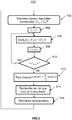
- the method operated by the location module 108 begins during an interaction, by a step 402 of acquisition of the values sent by the local force measurement modules 106-i of each fork sensor.
- a next step 404 the received data is shaped to determine a current value of the weight exerted, the static bias is removed, and the weight exerted on the surface is calculated (step 406).
- the calculated weight (removed from the static bias) is compared to a threshold value 'Threshold_weight'.
- the threshold value is set and defined at design in order to achieve a compromise between the sensitivity of the desired interaction and the electrical and mechanical disturbances of the system.
- step 416 If the calculated weight is greater than the threshold value, the method proceeds to step 416 considering that an interaction is occurring and that the deviation of the sensors is due to it.
- the process proceeds with steps 410, 412, 414 considering that there is no interaction with a user, that the surface is assumed free without any touch and that the residual deviations are due to drifts assimilated to dynamic bias.
- the criterion for comparing the weight measured with the threshold value must be repeat for n cycles (410, 412) before the bias update (414). The number of n cycles required sets the disturbance dynamics.
- the locating method generally continues through steps 418, 420, 422 consisting of grouping and normalizing the pooled data (418), estimating the position the closest (420) and a filtering of the estimated positions (422).
- the regrouping step 418 consists in decoupling the X and Y axes of the surface, then in projecting on each of the axes the forces measured by the plurality of sensors arranged on the same coordinates on the perpendicular axis in order to deduce sensors known as " equivalent sensors ".
- the Figure 7 illustrates the projection of four sensors (C0 to C3) arranged on a surface of "equivalent sensor C o " . So the example of the sensors of the figure 7 produces four equivalent sensors.
- An equivalent sensor is the sum of the values of the projected sensors.
- a first equivalent sensor (702) on the X axis which is the projection of the sensors C0 and C1 is the sum of the values measured on the real sensors 'C0 + C1' located at the same coordinates.
- a second equivalent sensor (704) on the X axis corresponds to the projection of the sensors C2 and C3 and has the value of the sum 'C2 + C3'.
- the projection on the Y axis of the sensors C1 and C2 produces an equivalent sensor (706) having a value equal to the sum 'C1 + C2' of the values measured on the sensors C1 and C2.
- the projection on the Y axis sensors C0 and C3 produce an equivalent sensor (708) having a value equal to the sum 'C0 + C3' of the values measured on the sensors C0 and C3.
- step 418 of collapsing and normalizing the sensors the method proceeds to step 420 by calculating an estimate of the nearest position for the interaction.
- the method comprises discretizing (504) a first X axis into a set of ' L ' possible positions, L being a number defined according to the desired accuracy.
- L is a number defined according to the desired accuracy.
- a set of L 100 possible positions makes it possible to achieve an accuracy of the order of one centimeter for a surface one meter long.
- the process then enters a computation loop (506, 508, 510) for all defined positions.
- the method makes it possible to calculate, for each of the discrete positions denoted by 'L i ' and for each equivalent sensor ' n ', the difference between the normalized value of the sensor equivalent ' C ° n ' and a normalized value 'F n (i)' that this equivalent sensor would measure if it were at the studied position 'L i ' .
- the normalized value 'F n (i) ' is defined beforehand during a calibration step of the surface.
- the method increments the positions (508, 510) to calculate an individual position cost associated with the eligibility of a position ' i ' for each equivalent sensor.
- step 514 the method makes it possible to determine the discrete position 'L i ' on the considered axis which minimizes the general position cost. Then the process generates in step 516, the selected position, corresponding to the best estimate of the position of the interaction on the axis considered.
- step 420 may be repeated for the second Y axis, for Y j coordinates and for discrete positions L j .
- the method described can be applied only for the X axis and combined with a known technique for calculating the barycentre for the second axis Y.
- the locating method of the invention is robust because it takes into account all the disparities of the system by an initial calibration step which is performed at commissioning, and which can also simply be reset in case system modification.
- step 420 produces the coordinates X i and Y j of the estimated position closest to the interaction.
- the position of the interaction estimated at the output of step 420 may not be used directly because it may be noisy and sometimes erroneous, especially during the dynamic phases of the touch, or by unreliability, particularly with regard to the dynamics of the sensors used.
- a filtering step 422 may be added to the method, as described with reference to the figure 6 .
- Measurement filtering via a low-pass filter is applied to eliminate outliers.
- Adjustable thresholds make it possible to define the cutoff frequency of the filter as well as to harden or lighten the criterion of rejection of the points. These thresholds are set according to two main criteria, the desired precision and the refresh rate.
- a first step 602 the estimated positions are placed in a rotating buffer ' B ' of size ' SizeBuff ' defined during the design and a mean value ' Moy ' is calculated (step 604) for all the values recorded.
- the method makes it possible (608) to calculate the distances between the data placed in the buffer and the mean 'B [i] -Moy', and to compare the difference with a given threshold 'Fixed threshold_resistance', achieving a compromise between the precision sought and the reactivity of the system.
- the method allows the value to be retained and goes to the next value (610).
- the value concerned is excluded from the buffer in step 612, and the method processes a next value (614).
- the method enables the next step (616) to determine whether the number of remaining excluded values in the buffer is sufficient and compares it to a fixed ' threshold_exclusion' exclusion threshold, achieving a compromise between the desired accuracy and the responsiveness of the system.
- the average of all the values is updated by not taking only valid points to constitute the filtered output of the system.
- the exclusion threshold 'Threshold_exclusion' is mainly used to always guarantee a minimum bandwidth of the low-pass filter, in other words a sufficient number of points in the calculation of the average.
- the present description illustrates a preferred implementation of the invention, but is not limiting. It can be implemented from hardware and / or software elements. An example has been chosen to allow a good understanding of the principles of the invention, but it is in no way exhaustive and should allow the skilled person to make changes and implementation variants keeping the same principles.
Landscapes
- Engineering & Computer Science (AREA)
- General Engineering & Computer Science (AREA)
- Theoretical Computer Science (AREA)
- Human Computer Interaction (AREA)
- Physics & Mathematics (AREA)
- General Physics & Mathematics (AREA)
- Computer Hardware Design (AREA)
- Measurement Of Length, Angles, Or The Like Using Electric Or Magnetic Means (AREA)
- Force Measurement Appropriate To Specific Purposes (AREA)
- Position Input By Displaying (AREA)
Claims (17)
- Verfahren zum Orten einer Interaktion auf einer Oberfläche, die mit einer Vielzahl von Sensoren ausgestattet sind, die entlang Achsen (X, Y) mit den Koordinaten (Xi, Yj) positioniert sind, wobei jeder Sensor einen Wert liefern kann, der die bei einer Interaktion gemessene Kraft repräsentiert, wobei das Verfahren durch die folgenden Schritte gekennzeichnet ist:a) Berechnen (502), für jede Koordinate Xi, eines Wertes, der eine Kraft für einen äquivalenten Sensor repräsentiert, wobei der Wert jedes äquivalenten Sensors der Summe der Werte der auf der Oberfläche auf der Koordinate Xi positionierten Sensoren entspricht;b) Nutzen (506, 512) des Wertes jedes äquivalenten Sensors zum Modellieren der Verteilung der Kräfte auf mehrere vordefinierte diskrete Positionen 'Li' der X-Achse, wobei die Modellierung gemäß einem mit der Nähe der Messungen der Sensoren assoziierten Kostenkriterium mit den Referenzmodellen erfolgt, die durch Bewegen einer Prüfmasse zu bekannten Positionen der Oberfläche aufgestellt werden; undc) Bestimmen (514, 516) der diskreten Position 'Li' mit den geringsten Kosten, die die nächstliegende Position der Interaktion auf der X-Achse repräsentiert.
- Verfahren nach Anspruch 1, bei dem die Schritte a) und b) auch für jede Koordinate Yj der Y-Achse und für mehrere diskrete Positionen 'Lj' angewendet werden und bei dem Schritt c) die nächstliegende diskrete Position 'Lj' der Interaktion auf der Y-Achse bestimmt.
- Verfahren nach Anspruch 1 oder 2, das nach dem Rechenschritt a) einen Schritt (418) des Normalisierens der Werte jedes äquivalenten Sensors mit Bezug auf die Modellwerte von Referenzsensoren beinhaltet.
- Verfahren nach einem der Ansprüche 1 bis 3, bei dem der Modellierungsschritt b) die folgenden Schritte beinhaltet:- Berechnen (506), für jede diskrete Position 'Li', von individuellen Positionskosten jedes äquivalenten Sensors; und- Berechnen (512), für jede diskrete Position 'Li', von allgemeinen Positionskosten des äquivalenten Sensors in Abhängigkeit von den mehreren individuellen Positionskosten.
- Verfahren nach Anspruch 4, bei dem der Schritt des Berechnens von individuellen Kosten im Berechnen des Quadratwertes des Abstands zwischen dem normalisierten Wert des äquivalenten Sensors und einem normalisierten Wert besteht, den der äquivalente Sensor an der diskreten Position 'Li' messen würde.
- Verfahren nach Anspruch 5, das einen vorläufigen Kalibrationsschritt beinhaltet, der das Definieren des normalisierten Wertes zulässt.
- Verfahren nach einem der Ansprüche 1 bis 6, das ferner nach Schritt c) einen Schritt (422) des Filterns der bestimmten Positionen beinhaltet.
- Verfahren nach Anspruch 7, bei dem das Filtern mit einem Tiefpassfilter erfolgt.
- Verfahren nach Anspruch 8, bei dem die Frequenz des Filters gemäß regelbaren Schwellen definiert wird.
- Verfahren nach einem der Ansprüche 1 bis 9, das ferner vor Schritt a) einen Schritt (402, 404, 406, 408) des Bestimmens einer Interaktion auf der Oberfläche beinhaltet.
- Verfahren nach Anspruch 10, bei dem der Schritt des Bestimmens einer Interaktion im Messen (406) eines auf die Oberfläche aufgebrachten Gewichts und im Bestimmen (408) besteht, ob das gemessene Gewicht größer ist als ein Schwellenwert.
- Verfahren nach Anspruch 11, bei dem eine statischer Verzerrungswert vom Messwert des aufgebrachten Gewichts subtrahiert (404) wird.
- Computerprogrammprodukt, wobei das Computerprogramm Code-Befehle umfasst, die es zulassen, die Schritte des Verfahrens nach einem der Ansprüche 1 bis 12 durchzuführen, wenn das Programm auf einem Computer ausgeführt wird.
- Vorrichtung zum Orten einer Interaktion auf einer Oberfläche, die mit einer Vielzahl von Sensoren (104_i, 106-i) ausgestattet ist, die entlang Achsen (X, Y) bei den Koordinaten (Xi, Yj) positioniert sind, wobei jeder Sensor einen Wert liefern kann, der die bei einer Interaktion gemessene Kraft repräsentiert, wobei die Vorrichtung Mittel zum Durchführen der Schritte des Verfahrens nach einem der Ansprüche 1 bis 12 umfasst.
- Vorrichtung nach Anspruch 14, bei der die Oberfläche (202) in einem festen Gehäuse (204) eingeschlossen ist und die Vielzahl von Sensoren (210-a, 210-b) umfassen, die zwischen der Oberfläche und dem Gehäuse platziert sind.
- Vorrichtung nach Anspruch 14 oder 15, bei der die Vielzahl von Sensoren ebene kapazitive Sensoren umfasst, die unter der Oberfläche positioniert sind.
- Vorrichtung nach einem der Ansprüche 14 bis 16, bei der die Vielzahl von Sensoren gegabelte kapazitive Sensoren umfasst, wobei jeder gegabelte kapazitive Sensor zwei ebene kapazitive Sensoren umfasst, die zu einer einheitlichen kapazitiven Vorrichtung zusammengefügt und jeweils einander gegenüber auf und unter der Oberfläche positioniert sind.
Applications Claiming Priority (2)
| Application Number | Priority Date | Filing Date | Title |
|---|---|---|---|
| FR1455302A FR3022365B1 (fr) | 2014-06-11 | 2014-06-11 | Procede et dispositif pour localiser une interaction sur une surface tactile |
| PCT/EP2015/062763 WO2015189167A1 (fr) | 2014-06-11 | 2015-06-09 | Procede et dispositif pour localiser une interaction sur une surface tactile |
Publications (2)
| Publication Number | Publication Date |
|---|---|
| EP3155504A1 EP3155504A1 (de) | 2017-04-19 |
| EP3155504B1 true EP3155504B1 (de) | 2018-08-29 |
Family
ID=51352637
Family Applications (1)
| Application Number | Title | Priority Date | Filing Date |
|---|---|---|---|
| EP15727660.1A Not-in-force EP3155504B1 (de) | 2014-06-11 | 2015-06-09 | Verfahren, computerprogrammprodukt und vorrichtung zur ortung von interaktion auf einer berührungsempfindlichen oberfläche |
Country Status (6)
| Country | Link |
|---|---|
| US (1) | US10001864B2 (de) |
| EP (1) | EP3155504B1 (de) |
| JP (1) | JP6495341B2 (de) |
| CN (1) | CN106575134A (de) |
| FR (1) | FR3022365B1 (de) |
| WO (1) | WO2015189167A1 (de) |
Cited By (1)
| Publication number | Priority date | Publication date | Assignee | Title |
|---|---|---|---|---|
| EP4273521A1 (de) | 2022-05-02 | 2023-11-08 | Saint-Gobain Glass France | System zur erkennung eines aufpralls auf eine autoglasscheibe |
Families Citing this family (2)
| Publication number | Priority date | Publication date | Assignee | Title |
|---|---|---|---|---|
| CN106919289B (zh) * | 2017-03-10 | 2019-06-28 | 京东方科技集团股份有限公司 | 触控力检测方法、触控力检测装置、触控面板及显示装置 |
| JP7637457B2 (ja) * | 2020-12-25 | 2025-02-28 | パナソニックオートモーティブシステムズ株式会社 | 入力装置 |
Family Cites Families (12)
| Publication number | Priority date | Publication date | Assignee | Title |
|---|---|---|---|---|
| US3657475A (en) | 1969-03-19 | 1972-04-18 | Thomson Csf T Vt Sa | Position-indicating system |
| US6715359B2 (en) * | 2001-06-28 | 2004-04-06 | Tactex Controls Inc. | Pressure sensitive surfaces |
| US7158122B2 (en) * | 2002-05-17 | 2007-01-02 | 3M Innovative Properties Company | Calibration of force based touch panel systems |
| JP2005030901A (ja) * | 2003-07-11 | 2005-02-03 | Alps Electric Co Ltd | 容量センサ |
| US7331245B2 (en) * | 2005-11-22 | 2008-02-19 | Avago Technologies Ecbu Ip Pte Ltd | Pressure distribution sensor and sensing method |
| JP5193942B2 (ja) * | 2009-05-14 | 2013-05-08 | 京セラディスプレイ株式会社 | 静電容量型タッチパネル装置 |
| US9262002B2 (en) * | 2010-11-03 | 2016-02-16 | Qualcomm Incorporated | Force sensing touch screen |
| JP2013065096A (ja) * | 2011-09-15 | 2013-04-11 | Hitachi Consumer Electronics Co Ltd | 入力機能付き表示装置および入力機能補正方法 |
| JP5809526B2 (ja) * | 2011-11-01 | 2015-11-11 | アルプス電気株式会社 | 入力装置及びキャリブレーション方法 |
| JP5855121B2 (ja) * | 2011-11-01 | 2016-02-09 | アルプス電気株式会社 | 入力装置及び押圧点検出方法 |
| JP5460758B2 (ja) * | 2012-01-31 | 2014-04-02 | 富士ソフト株式会社 | タッチパネルのタッチ位置補正処理方法及びプログラム |
| US8890824B2 (en) * | 2012-02-07 | 2014-11-18 | Atmel Corporation | Connecting conductive layers using in-mould lamination and decoration |
-
2014
- 2014-06-11 FR FR1455302A patent/FR3022365B1/fr not_active Expired - Fee Related
-
2015
- 2015-06-09 EP EP15727660.1A patent/EP3155504B1/de not_active Not-in-force
- 2015-06-09 JP JP2016572534A patent/JP6495341B2/ja not_active Expired - Fee Related
- 2015-06-09 WO PCT/EP2015/062763 patent/WO2015189167A1/fr not_active Ceased
- 2015-06-09 US US15/315,312 patent/US10001864B2/en active Active
- 2015-06-09 CN CN201580041398.6A patent/CN106575134A/zh not_active Withdrawn
Cited By (2)
| Publication number | Priority date | Publication date | Assignee | Title |
|---|---|---|---|---|
| EP4273521A1 (de) | 2022-05-02 | 2023-11-08 | Saint-Gobain Glass France | System zur erkennung eines aufpralls auf eine autoglasscheibe |
| WO2023213680A1 (en) | 2022-05-02 | 2023-11-09 | Saint-Gobain Glass France | Automotive glazing impact detection system |
Also Published As
| Publication number | Publication date |
|---|---|
| US10001864B2 (en) | 2018-06-19 |
| US20170123549A1 (en) | 2017-05-04 |
| JP2017521767A (ja) | 2017-08-03 |
| JP6495341B2 (ja) | 2019-04-03 |
| FR3022365A1 (fr) | 2015-12-18 |
| EP3155504A1 (de) | 2017-04-19 |
| CN106575134A (zh) | 2017-04-19 |
| WO2015189167A1 (fr) | 2015-12-17 |
| FR3022365B1 (fr) | 2016-05-27 |
Similar Documents
| Publication | Publication Date | Title |
|---|---|---|
| EP3697245B1 (de) | System und verfahren zur gangalnalyse und -quantifizierung eines benutzers | |
| EP3958738B1 (de) | Verfahren und system zur bestimmung eines wertes eines fortgeschrittenen biomechanischen gangparameters | |
| EP3155504B1 (de) | Verfahren, computerprogrammprodukt und vorrichtung zur ortung von interaktion auf einer berührungsempfindlichen oberfläche | |
| WO2013057447A1 (fr) | Procédé de détection d'activité à capteur de mouvements, dispositif et programme d'ordinateur correspondants | |
| EP3089888A1 (de) | Verfahren, vorrichtung und system zur messung des integritätszustandes einer batterie in einem elektro- oder hybridfahrzeug während des betriebs und verfahren zur erstellung eines modells für solch eine messung | |
| WO2021058701A1 (fr) | Procede et systeme pour le calcul de valeurs personnalisees de parametres d'une semelle pour la conception de semelles sur mesure | |
| EP3305186B1 (de) | Verfahren und system zur stressüberwachung eines benutzers | |
| EP3308104B1 (de) | Verfahren zur verarbeitung von messungen von mindestens einem elektronischen sensor in einer tragbaren vorrichtung | |
| FR2811753A1 (fr) | Pese-personne de poche | |
| CN107481282B (zh) | 体积测算方法、装置及用户终端 | |
| WO2022219289A1 (fr) | Procédé d'encodage de données de capteur de mouvement, dispositif et système associés | |
| EP0483914A1 (de) | Vorrichtung zur selektiven Auffindung eines Objekts | |
| EP4033931A1 (de) | Verfahren und system zur analyse der verwendung eines schuhartikels | |
| FR3121831A1 (fr) | Procédé d’encodage de données de capteur de mouvement, dispositif et système associés | |
| FR2988188A1 (fr) | Procede pour determiner l'activation d'au moins une touche d'un dispositif multitouches | |
| WO2023017227A1 (fr) | Systeme et procede pour la recommandation de semelle ou d'article chaussant a un utilisateur | |
| EP1078321A1 (de) | Verfahren zur wiederherstellung einer fläche mittels linearer prädiktion und anwendungen des verfahrens | |
| FR3003029A1 (fr) | Capteur capacitif de contrainte mecanique, ensemble de capteurs et dispositif de localisation de toucher a capteurs capacitifs | |
| EP3714773A1 (de) | System zur charakterisierung der körperhaltung und des gangs | |
| EP3465648B1 (de) | Verfahren und system zur erkennung von personen am boden | |
| EP3066525A1 (de) | Computersystem zur verarbeitung von heterogenen messungen aus verschiedenen metrologievorrichtungen im hinblick auf werteschätzung von merkmalen mikroelektronischer vorrichtungen, entsprechendes verfahren und computerprogramm | |
| FR3037701A1 (fr) | Procede d'estimation et de prevision d'indicateur de production d'energie d'un systeme solaire | |
| FR3006757A1 (fr) | Procede pour caracteriser un objet d'interet en interaction avec une interface de mesure, et dispositif mettant en oeuvre le procede | |
| FR3144345A1 (fr) | Gant a retour haptique pour la communication entre personnes |
Legal Events
| Date | Code | Title | Description |
|---|---|---|---|
| STAA | Information on the status of an ep patent application or granted ep patent |
Free format text: STATUS: THE INTERNATIONAL PUBLICATION HAS BEEN MADE |
|
| PUAI | Public reference made under article 153(3) epc to a published international application that has entered the european phase |
Free format text: ORIGINAL CODE: 0009012 |
|
| STAA | Information on the status of an ep patent application or granted ep patent |
Free format text: STATUS: REQUEST FOR EXAMINATION WAS MADE |
|
| 17P | Request for examination filed |
Effective date: 20170104 |
|
| AK | Designated contracting states |
Kind code of ref document: A1 Designated state(s): AL AT BE BG CH CY CZ DE DK EE ES FI FR GB GR HR HU IE IS IT LI LT LU LV MC MK MT NL NO PL PT RO RS SE SI SK SM TR |
|
| AX | Request for extension of the european patent |
Extension state: BA ME |
|
| DAV | Request for validation of the european patent (deleted) | ||
| DAX | Request for extension of the european patent (deleted) | ||
| GRAP | Despatch of communication of intention to grant a patent |
Free format text: ORIGINAL CODE: EPIDOSNIGR1 |
|
| STAA | Information on the status of an ep patent application or granted ep patent |
Free format text: STATUS: GRANT OF PATENT IS INTENDED |
|
| GRAS | Grant fee paid |
Free format text: ORIGINAL CODE: EPIDOSNIGR3 |
|
| INTG | Intention to grant announced |
Effective date: 20180618 |
|
| GRAA | (expected) grant |
Free format text: ORIGINAL CODE: 0009210 |
|
| STAA | Information on the status of an ep patent application or granted ep patent |
Free format text: STATUS: THE PATENT HAS BEEN GRANTED |
|
| AK | Designated contracting states |
Kind code of ref document: B1 Designated state(s): AL AT BE BG CH CY CZ DE DK EE ES FI FR GB GR HR HU IE IS IT LI LT LU LV MC MK MT NL NO PL PT RO RS SE SI SK SM TR |
|
| REG | Reference to a national code |
Ref country code: GB Ref legal event code: FG4D Free format text: NOT ENGLISH |
|
| REG | Reference to a national code |
Ref country code: CH Ref legal event code: EP |
|
| REG | Reference to a national code |
Ref country code: AT Ref legal event code: REF Ref document number: 1035895 Country of ref document: AT Kind code of ref document: T Effective date: 20180915 |
|
| REG | Reference to a national code |
Ref country code: IE Ref legal event code: FG4D Free format text: LANGUAGE OF EP DOCUMENT: FRENCH |
|
| REG | Reference to a national code |
Ref country code: DE Ref legal event code: R096 Ref document number: 602015015582 Country of ref document: DE |
|
| REG | Reference to a national code |
Ref country code: NL Ref legal event code: MP Effective date: 20180829 |
|
| REG | Reference to a national code |
Ref country code: LT Ref legal event code: MG4D |
|
| PG25 | Lapsed in a contracting state [announced via postgrant information from national office to epo] |
Ref country code: BG Free format text: LAPSE BECAUSE OF FAILURE TO SUBMIT A TRANSLATION OF THE DESCRIPTION OR TO PAY THE FEE WITHIN THE PRESCRIBED TIME-LIMIT Effective date: 20181129 Ref country code: SE Free format text: LAPSE BECAUSE OF FAILURE TO SUBMIT A TRANSLATION OF THE DESCRIPTION OR TO PAY THE FEE WITHIN THE PRESCRIBED TIME-LIMIT Effective date: 20180829 Ref country code: RS Free format text: LAPSE BECAUSE OF FAILURE TO SUBMIT A TRANSLATION OF THE DESCRIPTION OR TO PAY THE FEE WITHIN THE PRESCRIBED TIME-LIMIT Effective date: 20180829 Ref country code: NL Free format text: LAPSE BECAUSE OF FAILURE TO SUBMIT A TRANSLATION OF THE DESCRIPTION OR TO PAY THE FEE WITHIN THE PRESCRIBED TIME-LIMIT Effective date: 20180829 Ref country code: IS Free format text: LAPSE BECAUSE OF FAILURE TO SUBMIT A TRANSLATION OF THE DESCRIPTION OR TO PAY THE FEE WITHIN THE PRESCRIBED TIME-LIMIT Effective date: 20181229 Ref country code: NO Free format text: LAPSE BECAUSE OF FAILURE TO SUBMIT A TRANSLATION OF THE DESCRIPTION OR TO PAY THE FEE WITHIN THE PRESCRIBED TIME-LIMIT Effective date: 20181129 Ref country code: FI Free format text: LAPSE BECAUSE OF FAILURE TO SUBMIT A TRANSLATION OF THE DESCRIPTION OR TO PAY THE FEE WITHIN THE PRESCRIBED TIME-LIMIT Effective date: 20180829 Ref country code: GR Free format text: LAPSE BECAUSE OF FAILURE TO SUBMIT A TRANSLATION OF THE DESCRIPTION OR TO PAY THE FEE WITHIN THE PRESCRIBED TIME-LIMIT Effective date: 20181130 Ref country code: LT Free format text: LAPSE BECAUSE OF FAILURE TO SUBMIT A TRANSLATION OF THE DESCRIPTION OR TO PAY THE FEE WITHIN THE PRESCRIBED TIME-LIMIT Effective date: 20180829 |
|
| REG | Reference to a national code |
Ref country code: AT Ref legal event code: MK05 Ref document number: 1035895 Country of ref document: AT Kind code of ref document: T Effective date: 20180829 |
|
| PG25 | Lapsed in a contracting state [announced via postgrant information from national office to epo] |
Ref country code: LV Free format text: LAPSE BECAUSE OF FAILURE TO SUBMIT A TRANSLATION OF THE DESCRIPTION OR TO PAY THE FEE WITHIN THE PRESCRIBED TIME-LIMIT Effective date: 20180829 Ref country code: HR Free format text: LAPSE BECAUSE OF FAILURE TO SUBMIT A TRANSLATION OF THE DESCRIPTION OR TO PAY THE FEE WITHIN THE PRESCRIBED TIME-LIMIT Effective date: 20180829 Ref country code: AL Free format text: LAPSE BECAUSE OF FAILURE TO SUBMIT A TRANSLATION OF THE DESCRIPTION OR TO PAY THE FEE WITHIN THE PRESCRIBED TIME-LIMIT Effective date: 20180829 |
|
| PG25 | Lapsed in a contracting state [announced via postgrant information from national office to epo] |
Ref country code: RO Free format text: LAPSE BECAUSE OF FAILURE TO SUBMIT A TRANSLATION OF THE DESCRIPTION OR TO PAY THE FEE WITHIN THE PRESCRIBED TIME-LIMIT Effective date: 20180829 Ref country code: PL Free format text: LAPSE BECAUSE OF FAILURE TO SUBMIT A TRANSLATION OF THE DESCRIPTION OR TO PAY THE FEE WITHIN THE PRESCRIBED TIME-LIMIT Effective date: 20180829 Ref country code: ES Free format text: LAPSE BECAUSE OF FAILURE TO SUBMIT A TRANSLATION OF THE DESCRIPTION OR TO PAY THE FEE WITHIN THE PRESCRIBED TIME-LIMIT Effective date: 20180829 Ref country code: CZ Free format text: LAPSE BECAUSE OF FAILURE TO SUBMIT A TRANSLATION OF THE DESCRIPTION OR TO PAY THE FEE WITHIN THE PRESCRIBED TIME-LIMIT Effective date: 20180829 Ref country code: IT Free format text: LAPSE BECAUSE OF FAILURE TO SUBMIT A TRANSLATION OF THE DESCRIPTION OR TO PAY THE FEE WITHIN THE PRESCRIBED TIME-LIMIT Effective date: 20180829 Ref country code: EE Free format text: LAPSE BECAUSE OF FAILURE TO SUBMIT A TRANSLATION OF THE DESCRIPTION OR TO PAY THE FEE WITHIN THE PRESCRIBED TIME-LIMIT Effective date: 20180829 Ref country code: AT Free format text: LAPSE BECAUSE OF FAILURE TO SUBMIT A TRANSLATION OF THE DESCRIPTION OR TO PAY THE FEE WITHIN THE PRESCRIBED TIME-LIMIT Effective date: 20180829 |
|
| PG25 | Lapsed in a contracting state [announced via postgrant information from national office to epo] |
Ref country code: SM Free format text: LAPSE BECAUSE OF FAILURE TO SUBMIT A TRANSLATION OF THE DESCRIPTION OR TO PAY THE FEE WITHIN THE PRESCRIBED TIME-LIMIT Effective date: 20180829 Ref country code: DK Free format text: LAPSE BECAUSE OF FAILURE TO SUBMIT A TRANSLATION OF THE DESCRIPTION OR TO PAY THE FEE WITHIN THE PRESCRIBED TIME-LIMIT Effective date: 20180829 Ref country code: SK Free format text: LAPSE BECAUSE OF FAILURE TO SUBMIT A TRANSLATION OF THE DESCRIPTION OR TO PAY THE FEE WITHIN THE PRESCRIBED TIME-LIMIT Effective date: 20180829 |
|
| REG | Reference to a national code |
Ref country code: DE Ref legal event code: R097 Ref document number: 602015015582 Country of ref document: DE |
|
| PLBE | No opposition filed within time limit |
Free format text: ORIGINAL CODE: 0009261 |
|
| STAA | Information on the status of an ep patent application or granted ep patent |
Free format text: STATUS: NO OPPOSITION FILED WITHIN TIME LIMIT |
|
| 26N | No opposition filed |
Effective date: 20190531 |
|
| PG25 | Lapsed in a contracting state [announced via postgrant information from national office to epo] |
Ref country code: SI Free format text: LAPSE BECAUSE OF FAILURE TO SUBMIT A TRANSLATION OF THE DESCRIPTION OR TO PAY THE FEE WITHIN THE PRESCRIBED TIME-LIMIT Effective date: 20180829 |
|
| PG25 | Lapsed in a contracting state [announced via postgrant information from national office to epo] |
Ref country code: MC Free format text: LAPSE BECAUSE OF FAILURE TO SUBMIT A TRANSLATION OF THE DESCRIPTION OR TO PAY THE FEE WITHIN THE PRESCRIBED TIME-LIMIT Effective date: 20180829 |
|
| REG | Reference to a national code |
Ref country code: CH Ref legal event code: PL |
|
| REG | Reference to a national code |
Ref country code: BE Ref legal event code: MM Effective date: 20190630 |
|
| PG25 | Lapsed in a contracting state [announced via postgrant information from national office to epo] |
Ref country code: TR Free format text: LAPSE BECAUSE OF FAILURE TO SUBMIT A TRANSLATION OF THE DESCRIPTION OR TO PAY THE FEE WITHIN THE PRESCRIBED TIME-LIMIT Effective date: 20180829 |
|
| PG25 | Lapsed in a contracting state [announced via postgrant information from national office to epo] |
Ref country code: IE Free format text: LAPSE BECAUSE OF NON-PAYMENT OF DUE FEES Effective date: 20190609 |
|
| PG25 | Lapsed in a contracting state [announced via postgrant information from national office to epo] |
Ref country code: CH Free format text: LAPSE BECAUSE OF NON-PAYMENT OF DUE FEES Effective date: 20190630 Ref country code: LI Free format text: LAPSE BECAUSE OF NON-PAYMENT OF DUE FEES Effective date: 20190630 Ref country code: BE Free format text: LAPSE BECAUSE OF NON-PAYMENT OF DUE FEES Effective date: 20190630 Ref country code: LU Free format text: LAPSE BECAUSE OF NON-PAYMENT OF DUE FEES Effective date: 20190609 |
|
| PG25 | Lapsed in a contracting state [announced via postgrant information from national office to epo] |
Ref country code: PT Free format text: LAPSE BECAUSE OF FAILURE TO SUBMIT A TRANSLATION OF THE DESCRIPTION OR TO PAY THE FEE WITHIN THE PRESCRIBED TIME-LIMIT Effective date: 20181229 |
|
| PGFP | Annual fee paid to national office [announced via postgrant information from national office to epo] |
Ref country code: GB Payment date: 20200619 Year of fee payment: 6 |
|
| PG25 | Lapsed in a contracting state [announced via postgrant information from national office to epo] |
Ref country code: CY Free format text: LAPSE BECAUSE OF FAILURE TO SUBMIT A TRANSLATION OF THE DESCRIPTION OR TO PAY THE FEE WITHIN THE PRESCRIBED TIME-LIMIT Effective date: 20180829 |
|
| PG25 | Lapsed in a contracting state [announced via postgrant information from national office to epo] |
Ref country code: HU Free format text: LAPSE BECAUSE OF FAILURE TO SUBMIT A TRANSLATION OF THE DESCRIPTION OR TO PAY THE FEE WITHIN THE PRESCRIBED TIME-LIMIT; INVALID AB INITIO Effective date: 20150609 Ref country code: MT Free format text: LAPSE BECAUSE OF FAILURE TO SUBMIT A TRANSLATION OF THE DESCRIPTION OR TO PAY THE FEE WITHIN THE PRESCRIBED TIME-LIMIT Effective date: 20180829 |
|
| GBPC | Gb: european patent ceased through non-payment of renewal fee |
Effective date: 20210609 |
|
| PG25 | Lapsed in a contracting state [announced via postgrant information from national office to epo] |
Ref country code: GB Free format text: LAPSE BECAUSE OF NON-PAYMENT OF DUE FEES Effective date: 20210609 |
|
| PG25 | Lapsed in a contracting state [announced via postgrant information from national office to epo] |
Ref country code: MK Free format text: LAPSE BECAUSE OF FAILURE TO SUBMIT A TRANSLATION OF THE DESCRIPTION OR TO PAY THE FEE WITHIN THE PRESCRIBED TIME-LIMIT Effective date: 20180829 |
|
| PGFP | Annual fee paid to national office [announced via postgrant information from national office to epo] |
Ref country code: DE Payment date: 20230620 Year of fee payment: 9 |
|
| PGFP | Annual fee paid to national office [announced via postgrant information from national office to epo] |
Ref country code: FR Payment date: 20240624 Year of fee payment: 10 |
|
| REG | Reference to a national code |
Ref country code: DE Ref legal event code: R119 Ref document number: 602015015582 Country of ref document: DE |
|
| PG25 | Lapsed in a contracting state [announced via postgrant information from national office to epo] |
Ref country code: DE Free format text: LAPSE BECAUSE OF NON-PAYMENT OF DUE FEES Effective date: 20260101 |
|
| PG25 | Lapsed in a contracting state [announced via postgrant information from national office to epo] |
Ref country code: FR Free format text: LAPSE BECAUSE OF NON-PAYMENT OF DUE FEES Effective date: 20250630 |