EP3155258B1 - A tip system for a wind turbine blade - Google Patents
A tip system for a wind turbine blade Download PDFInfo
- Publication number
- EP3155258B1 EP3155258B1 EP15729795.3A EP15729795A EP3155258B1 EP 3155258 B1 EP3155258 B1 EP 3155258B1 EP 15729795 A EP15729795 A EP 15729795A EP 3155258 B1 EP3155258 B1 EP 3155258B1
- Authority
- EP
- European Patent Office
- Prior art keywords
- section
- recess
- leading edge
- trailing edge
- layup
- Prior art date
- Legal status (The legal status is an assumption and is not a legal conclusion. Google has not performed a legal analysis and makes no representation as to the accuracy of the status listed.)
- Active
Links
- 239000000463 material Substances 0.000 claims description 44
- 239000000835 fiber Substances 0.000 claims description 39
- 238000000034 method Methods 0.000 claims description 37
- 238000005304 joining Methods 0.000 claims description 36
- 239000011347 resin Substances 0.000 claims description 30
- 229920005989 resin Polymers 0.000 claims description 30
- 210000001503 joint Anatomy 0.000 claims description 25
- 239000000853 adhesive Substances 0.000 claims description 18
- 230000001070 adhesive effect Effects 0.000 claims description 18
- 238000001802 infusion Methods 0.000 claims description 12
- 238000004519 manufacturing process Methods 0.000 claims description 9
- 238000004026 adhesive bonding Methods 0.000 claims description 4
- 238000009736 wetting Methods 0.000 claims description 4
- 239000011162 core material Substances 0.000 description 25
- 230000008878 coupling Effects 0.000 description 22
- 238000010168 coupling process Methods 0.000 description 22
- 238000005859 coupling reaction Methods 0.000 description 22
- 239000007787 solid Substances 0.000 description 6
- 230000007704 transition Effects 0.000 description 6
- 238000010276 construction Methods 0.000 description 5
- 238000013461 design Methods 0.000 description 4
- OKTJSMMVPCPJKN-UHFFFAOYSA-N Carbon Chemical compound [C] OKTJSMMVPCPJKN-UHFFFAOYSA-N 0.000 description 3
- 229920002430 Fibre-reinforced plastic Polymers 0.000 description 3
- 229910052799 carbon Inorganic materials 0.000 description 3
- 239000003292 glue Substances 0.000 description 3
- 238000003475 lamination Methods 0.000 description 3
- 238000000465 moulding Methods 0.000 description 3
- 125000006850 spacer group Chemical group 0.000 description 3
- 229910000831 Steel Inorganic materials 0.000 description 2
- 230000009286 beneficial effect Effects 0.000 description 2
- 239000002131 composite material Substances 0.000 description 2
- 239000011151 fibre-reinforced plastic Substances 0.000 description 2
- 239000011888 foil Substances 0.000 description 2
- 239000003365 glass fiber Substances 0.000 description 2
- 238000003780 insertion Methods 0.000 description 2
- 230000037431 insertion Effects 0.000 description 2
- 238000003908 quality control method Methods 0.000 description 2
- 239000010959 steel Substances 0.000 description 2
- 238000011179 visual inspection Methods 0.000 description 2
- 230000007423 decrease Effects 0.000 description 1
- 230000001419 dependent effect Effects 0.000 description 1
- 239000006260 foam Substances 0.000 description 1
- 239000011521 glass Substances 0.000 description 1
- 238000000227 grinding Methods 0.000 description 1
- 238000010438 heat treatment Methods 0.000 description 1
- 238000002347 injection Methods 0.000 description 1
- 239000007924 injection Substances 0.000 description 1
- 230000010354 integration Effects 0.000 description 1
- 230000013011 mating Effects 0.000 description 1
- 229910052751 metal Inorganic materials 0.000 description 1
- 239000011208 reinforced composite material Substances 0.000 description 1
- 230000002787 reinforcement Effects 0.000 description 1
- 230000000717 retained effect Effects 0.000 description 1
- 229920006395 saturated elastomer Polymers 0.000 description 1
- 238000007789 sealing Methods 0.000 description 1
- 239000011343 solid material Substances 0.000 description 1
- 238000012546 transfer Methods 0.000 description 1
- 229920001567 vinyl ester resin Polymers 0.000 description 1
- 238000009756 wet lay-up Methods 0.000 description 1
Images


Classifications
-
- F—MECHANICAL ENGINEERING; LIGHTING; HEATING; WEAPONS; BLASTING
- F03—MACHINES OR ENGINES FOR LIQUIDS; WIND, SPRING, OR WEIGHT MOTORS; PRODUCING MECHANICAL POWER OR A REACTIVE PROPULSIVE THRUST, NOT OTHERWISE PROVIDED FOR
- F03D—WIND MOTORS
- F03D1/00—Wind motors with rotation axis substantially parallel to the air flow entering the rotor
- F03D1/06—Rotors
- F03D1/065—Rotors characterised by their construction elements
- F03D1/0675—Rotors characterised by their construction elements of the blades
-
- B—PERFORMING OPERATIONS; TRANSPORTING
- B29—WORKING OF PLASTICS; WORKING OF SUBSTANCES IN A PLASTIC STATE IN GENERAL
- B29C—SHAPING OR JOINING OF PLASTICS; SHAPING OF MATERIAL IN A PLASTIC STATE, NOT OTHERWISE PROVIDED FOR; AFTER-TREATMENT OF THE SHAPED PRODUCTS, e.g. REPAIRING
- B29C65/00—Joining or sealing of preformed parts, e.g. welding of plastics materials; Apparatus therefor
- B29C65/48—Joining or sealing of preformed parts, e.g. welding of plastics materials; Apparatus therefor using adhesives, i.e. using supplementary joining material; solvent bonding
-
- B—PERFORMING OPERATIONS; TRANSPORTING
- B29—WORKING OF PLASTICS; WORKING OF SUBSTANCES IN A PLASTIC STATE IN GENERAL
- B29C—SHAPING OR JOINING OF PLASTICS; SHAPING OF MATERIAL IN A PLASTIC STATE, NOT OTHERWISE PROVIDED FOR; AFTER-TREATMENT OF THE SHAPED PRODUCTS, e.g. REPAIRING
- B29C66/00—General aspects of processes or apparatus for joining preformed parts
- B29C66/001—Joining in special atmospheres
- B29C66/0012—Joining in special atmospheres characterised by the type of environment
- B29C66/0014—Gaseous environments
- B29C66/00145—Vacuum, e.g. partial vacuum
-
- B—PERFORMING OPERATIONS; TRANSPORTING
- B29—WORKING OF PLASTICS; WORKING OF SUBSTANCES IN A PLASTIC STATE IN GENERAL
- B29C—SHAPING OR JOINING OF PLASTICS; SHAPING OF MATERIAL IN A PLASTIC STATE, NOT OTHERWISE PROVIDED FOR; AFTER-TREATMENT OF THE SHAPED PRODUCTS, e.g. REPAIRING
- B29C66/00—General aspects of processes or apparatus for joining preformed parts
- B29C66/01—General aspects dealing with the joint area or with the area to be joined
- B29C66/05—Particular design of joint configurations
- B29C66/10—Particular design of joint configurations particular design of the joint cross-sections
- B29C66/11—Joint cross-sections comprising a single joint-segment, i.e. one of the parts to be joined comprising a single joint-segment in the joint cross-section
- B29C66/116—Single bevelled joints, i.e. one of the parts to be joined being bevelled in the joint area
- B29C66/1162—Single bevel to bevel joints, e.g. mitre joints
-
- B—PERFORMING OPERATIONS; TRANSPORTING
- B29—WORKING OF PLASTICS; WORKING OF SUBSTANCES IN A PLASTIC STATE IN GENERAL
- B29C—SHAPING OR JOINING OF PLASTICS; SHAPING OF MATERIAL IN A PLASTIC STATE, NOT OTHERWISE PROVIDED FOR; AFTER-TREATMENT OF THE SHAPED PRODUCTS, e.g. REPAIRING
- B29C66/00—General aspects of processes or apparatus for joining preformed parts
- B29C66/70—General aspects of processes or apparatus for joining preformed parts characterised by the composition, physical properties or the structure of the material of the parts to be joined; Joining with non-plastics material
- B29C66/72—General aspects of processes or apparatus for joining preformed parts characterised by the composition, physical properties or the structure of the material of the parts to be joined; Joining with non-plastics material characterised by the structure of the material of the parts to be joined
- B29C66/721—Fibre-reinforced materials
-
- B—PERFORMING OPERATIONS; TRANSPORTING
- B29—WORKING OF PLASTICS; WORKING OF SUBSTANCES IN A PLASTIC STATE IN GENERAL
- B29L—INDEXING SCHEME ASSOCIATED WITH SUBCLASS B29C, RELATING TO PARTICULAR ARTICLES
- B29L2031/00—Other particular articles
- B29L2031/08—Blades for rotors, stators, fans, turbines or the like, e.g. screw propellers
- B29L2031/082—Blades, e.g. for helicopters
- B29L2031/085—Wind turbine blades
-
- F—MECHANICAL ENGINEERING; LIGHTING; HEATING; WEAPONS; BLASTING
- F05—INDEXING SCHEMES RELATING TO ENGINES OR PUMPS IN VARIOUS SUBCLASSES OF CLASSES F01-F04
- F05B—INDEXING SCHEME RELATING TO WIND, SPRING, WEIGHT, INERTIA OR LIKE MOTORS, TO MACHINES OR ENGINES FOR LIQUIDS COVERED BY SUBCLASSES F03B, F03D AND F03G
- F05B2230/00—Manufacture
- F05B2230/20—Manufacture essentially without removing material
- F05B2230/23—Manufacture essentially without removing material by permanently joining parts together
-
- F—MECHANICAL ENGINEERING; LIGHTING; HEATING; WEAPONS; BLASTING
- F05—INDEXING SCHEMES RELATING TO ENGINES OR PUMPS IN VARIOUS SUBCLASSES OF CLASSES F01-F04
- F05B—INDEXING SCHEME RELATING TO WIND, SPRING, WEIGHT, INERTIA OR LIKE MOTORS, TO MACHINES OR ENGINES FOR LIQUIDS COVERED BY SUBCLASSES F03B, F03D AND F03G
- F05B2230/00—Manufacture
- F05B2230/30—Manufacture with deposition of material
- F05B2230/31—Layer deposition
-
- F—MECHANICAL ENGINEERING; LIGHTING; HEATING; WEAPONS; BLASTING
- F05—INDEXING SCHEMES RELATING TO ENGINES OR PUMPS IN VARIOUS SUBCLASSES OF CLASSES F01-F04
- F05B—INDEXING SCHEME RELATING TO WIND, SPRING, WEIGHT, INERTIA OR LIKE MOTORS, TO MACHINES OR ENGINES FOR LIQUIDS COVERED BY SUBCLASSES F03B, F03D AND F03G
- F05B2240/00—Components
- F05B2240/20—Rotors
- F05B2240/30—Characteristics of rotor blades, i.e. of any element transforming dynamic fluid energy to or from rotational energy and being attached to a rotor
- F05B2240/302—Segmented or sectional blades
-
- F—MECHANICAL ENGINEERING; LIGHTING; HEATING; WEAPONS; BLASTING
- F05—INDEXING SCHEMES RELATING TO ENGINES OR PUMPS IN VARIOUS SUBCLASSES OF CLASSES F01-F04
- F05B—INDEXING SCHEME RELATING TO WIND, SPRING, WEIGHT, INERTIA OR LIKE MOTORS, TO MACHINES OR ENGINES FOR LIQUIDS COVERED BY SUBCLASSES F03B, F03D AND F03G
- F05B2260/00—Function
- F05B2260/30—Retaining components in desired mutual position
-
- Y—GENERAL TAGGING OF NEW TECHNOLOGICAL DEVELOPMENTS; GENERAL TAGGING OF CROSS-SECTIONAL TECHNOLOGIES SPANNING OVER SEVERAL SECTIONS OF THE IPC; TECHNICAL SUBJECTS COVERED BY FORMER USPC CROSS-REFERENCE ART COLLECTIONS [XRACs] AND DIGESTS
- Y02—TECHNOLOGIES OR APPLICATIONS FOR MITIGATION OR ADAPTATION AGAINST CLIMATE CHANGE
- Y02E—REDUCTION OF GREENHOUSE GAS [GHG] EMISSIONS, RELATED TO ENERGY GENERATION, TRANSMISSION OR DISTRIBUTION
- Y02E10/00—Energy generation through renewable energy sources
- Y02E10/70—Wind energy
- Y02E10/72—Wind turbines with rotation axis in wind direction
-
- Y—GENERAL TAGGING OF NEW TECHNOLOGICAL DEVELOPMENTS; GENERAL TAGGING OF CROSS-SECTIONAL TECHNOLOGIES SPANNING OVER SEVERAL SECTIONS OF THE IPC; TECHNICAL SUBJECTS COVERED BY FORMER USPC CROSS-REFERENCE ART COLLECTIONS [XRACs] AND DIGESTS
- Y02—TECHNOLOGIES OR APPLICATIONS FOR MITIGATION OR ADAPTATION AGAINST CLIMATE CHANGE
- Y02P—CLIMATE CHANGE MITIGATION TECHNOLOGIES IN THE PRODUCTION OR PROCESSING OF GOODS
- Y02P70/00—Climate change mitigation technologies in the production process for final industrial or consumer products
- Y02P70/50—Manufacturing or production processes characterised by the final manufactured product
Definitions
- the present invention relates to a tip system for a wind turbine blade, and associated methods of manufacture and assembly.
- blades can be provided in modular form, having for example a separate tip section from a mainboard and/or root section.
- EP2634417A2 describes blade inserts that can be inserted between blade segments to make the resulting wind turbine blade longer.
- US2010/132884 describes the assembly of blade segments by insertion of spar cap segments into each other and filling a resulting gap with adhesive.
- US2010/143062 describes a system for transporting and aligning a two-part wind turbine blade.
- the invention relates to a method of manufacturing a wind turbine blade by joining a tip section of the blade and a mainboard section of the blade at a joining section, wherein
- joining step e) comprises wetting a fibre material with resin and curing said resin, said fibre material being dry fibre material infused with resin in an infusion process, such as a vacuum assisted infusion process.
- the present manufacturing method forms a robust and durable joint between the mainboard and tip sections of a modular wind turbine blade.
- the method introduces no extra loads or stresses in the load carrying structure, whereby the method provides a blade of a durability and quality equaling a common non-modular wind turbine blade. Further, the method provides the opportunity to shape the layup such that the intended aerodynamic surface may be achieved and a smooth transition from the tip section to the mainboard section may be achieved.
- parts of fibre plies comprised in the principal load carrying laminate of the mainboard section may protrude at the taper section and into the air in the recess.
- These protruding fibre material can then be firmly integrated to a dry fibre layup, becoming an integral part of the layup, and after infusion with resin, a particularly strong connection may be formed.
- protruding fibre material may be provided in all tapering sections, partly pre-filling the recess.
- the second layup and the third layup is/are selected from the group consisting of a fibre material, a resin, a pre-formed part, an adhesive, a pre-preg material, a pre-cured element or any combination thereof.
- layup material for attachment to the recesses in the laminate(s) of the tip section and of the mainboard section may be varied for different reasons, including price, production speed, ease of handling and complexity of arranging such layups.
- the preformed part may be arranged to attached to the recesses by gluing.
- the joint may be further strengthened, for example, by overlaminating, so that at least the principal main laminates of the tip- and mainboard sections, that is, the first principal main laminate and the second principal main laminate, and optionally also the leading edge laminates of the tip- and mainboard sections as well as the trailing edge laminates of the tip- and mainboard sections, are overlaminated at predesigned positions in the shell attachment element. Further, the overlamination may form the outer surface of the blade and thus provide a smooth aerodynamic surface.
- said first recess, said second recess, said first leading edge recess, said second leading edge recess, said first trailing edge recess and said second trailing edge recess overlap to form a single recess around the circumference of the tip section and the mainboard section.
- the joining steps e1) and e2) comprise wetting a fibre material with resin and curing said resin, said fibre material being a pre-preg material and/or dry fibre material which then is infused with resin in an infusion process, such as a vacuum assisted infusion process.
- a very versatile and advantageous embodiment is achieved when joining the tip section with the motherboard section using fibre material very similar or substantially identical to the fibre material already comprised in the principal load carrying laminates.
- the fibre material may be a pre-preg material which is cured, e.g. by heating, after arranging one or more layers in the recesses.
- the fibre material may also be plies of dry fibre, which, after arranging them in the recesses, are infused with resin and cured.
- pre-preg material with dry fibre material in the recesses.
- the joining steps e1) and e2) comprise gluing a pre-cured element or a pre-formed part to the first leading edge recess and to the second leading edge recess, and/or to the first trailing edge recess and to the second trailing edge recess. It may be advantageous to use pre-formed parts glued into the recesses. This may be comparatively easy to handle. Furthermore, the quality of the pre-formed part may be assessed prior to arranging them in the recesses, making this option advantageous with respect to quality control.
- the joining section has a length of 1 - 5 m in the longitudinal direction.
- the joining section may need to have a minimum length.
- the width of the joining section is between 0.5m and the total width of the blade from a leading edge to a trailing edge.
- the taper has a depth to length ratio of between 1 to 30 and 1 to 2.
- the ratio of the length of the tip section to the length of the mainboard section is between 1 to 8 and 1 to 1, preferably between 1 to 4 and 1 to 2.
- the invention also relates to a wind turbine blade formed by joining a tip section and a mainboard section by the method of claim 1.
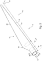
- Fig. 1 illustrates a conventional modern upwind wind turbine 2 according to the so-called "Danish concept" with a tower 4, a nacelle 6 and a rotor with a substantially horizontal rotor shaft.
- the rotor includes a hub 8 and three blades 10 extending radially from the hub 8, each having a blade root 16 nearest the hub and a blade tip 14 furthest from the hub 8.
- the rotor has a radius denoted R.
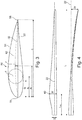
- Fig. 2 shows a schematic view of a wind turbine blade 10.
- the wind turbine blade 10 has the shape of a conventional wind turbine blade and comprises a root region 30 closest to the hub, a profiled or an airfoil region 34 furthest away from the hub and a transition region 32 between the root region 30 and the airfoil region 34.
- the blade 10 comprises a leading edge 18 facing the direction of rotation of the blade 10, when the blade is mounted on the hub, and a trailing edge 20 facing the opposite direction of the leading edge 18.
- the airfoil region 34 (also called the profiled region) has an ideal or almost ideal blade shape with respect to generating lift, whereas the root region 30 due to structural considerations has a substantially circular or elliptical cross-section, which for instance makes it easier and safer to mount the blade 10 to the hub.
- the diameter (or the chord) of the root region 30 is typically constant along the entire root area 30.
- the transition region 32 has a transitional profile 42 gradually changing from the circular or elliptical shape 40 of the root region 30 to the airfoil profile 50 of the airfoil region 34.
- the chord length of the transition region 32 typically increases substantially linearly with increasing distance r from the hub.
- the airfoil region 34 has an airfoil profile 50 with a chord extending between the leading edge 18 and the trailing edge 20 of the blade 10. The width of the chord decreases with increasing distance r from the hub.
- chords of different sections of the blade normally do not lie in a common plane, since the blade may be twisted and/or curved (i.e. pre-bent), thus providing the chord plane with a correspondingly twisted and/or curved course, this being most often the case in order to compensate for the local velocity of the blade being dependent on the radius from the hub.
- Fig. 3 shows a schematic view of an airfoil profile 50 of a typical blade of a wind turbine depicted with the various parameters, which are typically used to define the geometrical shape of an airfoil.
- the airfoil profile 50 has a pressure side 52 and a suction side 54, which during use - i.e. during rotation of the rotor - normally face towards the windward (or upwind) side and the leeward (or downwind) side, respectively.
- the airfoil 50 has a chord 60 with a chord length c extending between a leading edge 56 and a trailing edge 58 of the blade, known as the a chordwise direction.
- the airfoil 50 has a thickness t, which is defined as the distance between the pressure side 52 and the suction side 54.
- the thickness t of the airfoil varies along the chord 60.
- the deviation from a symmetrical profile is given by a camber line 62, which is a median line through the airfoil profile 50.
- the median line can be found by drawing inscribed circles from the leading edge 56 to the trailing edge 58.
- the median line follows the centres of these inscribed circles and the deviation or distance from the chord 60 is called the camber f .
- the asymmetry can also be defined by use of parameters called the upper camber (or suction side camber) and lower camber (or pressure side camber), which are defined as the distances from the chord 60 and the suction side 54 and pressure side 52, respectively.
- Airfoil profiles are often characterised by the following parameters: the chord length c, the maximum camber f, the position d f of the maximum camber f, the maximum airfoil thickness t, which is the largest diameter of the inscribed circles along the median camber line 62, the position d t of the maximum thickness t, and a nose radius (not shown). These parameters are typically defined as ratios to the chord length c. Thus, a local relative blade thickness t / c is given as the ratio between the local maximum thickness t and the local chord length c. Further, the position d p of the maximum pressure side camber may be used as a design parameter, and of course also the position of the maximum suction side camber.
- Fig. 4 shows some other geometric parameters of the blade.
- the diameter of the root is defined as D.
- the blade is provided with a prebend, which is defined as ⁇ y, which corresponds to the out of plane deflection from a pitch axis 22 of the blade.
- the wind turbine blade 10 generally comprises a shell made of fibre-reinforced polymer, and is typically made as a pressure side or upwind shell part 24 and a suction side or downwind shell part 26 that are glued together along bond lines 28 extending along the trailing edge 20 and the leading edge 18 of the blade 10.
- Wind turbine blades are generally formed from fibre-reinforced plastics material, e.g. glass fibres and/or carbon fibres which are arranged in a mould and cured with a resin to form a solid structure. Modern wind turbine blades can often be in excess of 30 or 40 metres in length, having blade root diameters of several metres. Wind turbine blades are generally designed for relatively long lifetimes and to withstand considerable structural and dynamic loading.
- the wind turbine blade is initially provided in at least two sections - at least a first section towards the tip end 14 of the blade 10, the tip end section indicated generally at 70, and at least a section comprising the root end 16 of the blade 10, herein referred to as the mainboard section 72.
- the separate sections 70,72 can be joined together to form at least a portion of the wind turbine blade 10.
- connection between the sections 70,72 must be light weight and durable. While Fig. 4 shows a pre-bent blade, it will be understood that no pre-bend is necessary in the tip section 70. Preferably, the tip section 70 comprises 1/6th to 1/4th of the total blade length.
- the tip section 70 can be provided in a variety of different lengths and geometries, to allow for scalability of design.
- a first example of a tip system for a wind turbine blade is shown, showing a tip section 70a looking from the root-end-side of the tip section towards the tip end 14.
- the tip section 70a comprises three cores arranged to form a leading edge portion 71a, a trailing edge portion 71b, and a main laminate portion 71c.
- the core portions 71a,71b,71c are preferably three hollow braided infused cores, further preferably with pultruded profiles at the leading edge, trailing edge, and/or main laminate sections of the respective cores 71a,71b,71c.
- the cores 71a,71b,71c may comprise Glass Fibre Reinforced Polymer (GFRP), but it will be understood that carbon fibres may additionally or alternatively be used.
- GFRP Glass Fibre Reinforced Polymer
- the cores 71a,71b,71c can be positioned together to effectively form a mandrel or forming core, to which skin layers, which may comprise layers of glass and/or carbon fibre material, can be applied to or braided around.
- the package including the cores 71a,71b,71c and the skin layers 74, may be placed within a mould to form the desired shape of the tip section 70.
- the package can then be infused with a resin and cured to form the tip section 70.
- the package is infused in a one-shot moulding process.
- the skin layers 74 are preferably infused, but it will be understood that portions of the surfaces of the cores 71a,71b,71c may be infused with resin during the moulding process.
- the cores 71a,71b,71c may be formed on members (not shown) which may be retained in position within the interior of the cores 71a,71b,71c before and/or during the infusion process, and removed thereafter.
- the members may comprise relatively rigid elements, flexible filling material and/or inflatable elements for ease of removal.
- This embodiment provides a relatively light-weight tip section 70 which is relatively easy to manufacture, and may be suitable for automation.
- the tip section 70 comprises no adhesive bond lines, and accordingly eliminates the possibility of bond line failure in the tip section 70, while reducing the weight of the tip section 70.
- Scalability may be provided by simply lengthening tools used to form the core sections 71a,71b,71c
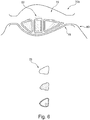
- FIG. 6 A similar embodiment is indicated in Fig. 6 , wherein a tip section 70b is shown looking from the root-end-side of the tip section towards the tip end 14.
- the cores 76 may be formed from a solid material, may comprise a vacuumised solid to form a core structure (e.g. grains), and/or may comprise a foam core provided with a sealing foil (e.g. to prevent the ingress of resin).
- the cores 76 may be arranged in a mould 78, preferably on top of at least one layer of fibre material, e.g. biax fibre material 80. Additional layers of fibre material may be provided adjacent the cores 76, e.g. unidirectional fibres 82 positioned beneath and on top of the cores 76 in the region of the main laminate portion of the tip section 70b. Further layers of fibre material (not shown) may be positioned on top of the cores 76 in the mould 78, before the mould 78 is closed and the fibre material infused with resin to form the tip section 70b.
- biax fibre material 80 e.g. biax fibre material 80. Additional layers of fibre material may be provided adjacent the cores 76, e.g. unidirectional fibres 82 positioned beneath and on top of the cores 76 in the region of the main laminate portion of the tip section 70b. Further layers of fibre material (not shown) may be positioned on top of the cores 76 in the mould 78, before the mould 78 is closed and
- non-hollow cores 76 Due to the use of non-hollow cores 76, it may be possible to reduce or eliminate the use of pultruded reinforcement elements in the tip section 70b, and/or to reduce or eliminate the use of separate forming members to form the initial cores.
- a portion of a tip section comprises non-hollow core sections and a portion comprises hollow core sections.
- FIG. 7 A further embodiment of a tip section 70c according to the invention is shown in Fig. 7 , wherein the tip section 70c comprises a central load-bearing section 82, preferably a load bearing beam or spar box, wherein non-load-carrying shape pieces 84 can be provided at the leading edge and/or the trailing edge of the tip section 70c.
- the tip section 70c is formed wherein non-load-carrying shape pieces 84 are attached at the leading edge and trailing edge sides of the load-bearing section 82, such that a portion of the load-bearing section 82 is exposed on the surface of the tip section 70c.
- non-load-carrying shape pieces 84 may alternatively be attached to the load-bearing section 82 wherein the non-load-carrying shape pieces 84 form a shell substantially around the entire load-bearing section 82, which is located in the interior of the tip section 70c.
- the non-load-carrying shape pieces 84 may be attached to the load-bearing section 82 using any suitable connection, e.g. adhesive bonding or bonding via resin infusion joint, mechanical connectors, e.g. bolting, riveting.
- the joint between components is not located at the leading edge or trailing edge, and accordingly may only experience loading due to aerodynamic forces.
- the load concentrations and load path can be easily calculated using the central load-bearing section 82, which can easily be designed as appropriate.
- the load-bearing section 82 may be manufactured using any suitable manufacturing process, and can be relatively easily scaled as desired.
- FIG. 8 an embodiment of a tip section connection according to the invention is illustrated for the embodiment of Fig. 7 .
- the central load-bearing section 82 extends from the tip section 70c to provide a connection member 82a, which can be received within an open end (not shown) of a mainboard section 72 of a sectional blade 10.
- the connection member 82a may be received within and connected to an appropriate portion of the mainboard section 72, e.g. internal shear webs, a spar box or beam, etc. (as illustrated in outline in Fig. 8 ).
- a tip section 70d is provided wherein a section 86 of the external surface of the section, e.g. on the upwind or downwind side of the tip section, is longer in the spanwise direction towards the root end 16 of the blade 10 than the opposite surface.
- the upwind side 86 may be 1-2 metres longer in the spanwise direction than the downwind side.
- the side on the opposed surface to the projecting side 86 of the tip section 70d extends longer in the spanwise direction towards the tip end 14 of the blade 10.
- the tip section 70d may be joined to the mainboard section by connecting the projecting portion of the tip section 70d with the projecting portion of the mainboard section.
- the sections may be joined using any suitable connection, as described above.
- adhesive is applied along at least a portion of the interface between the sections, e.g. along bond lines provided at the edges of the surfaces of the shells of the projecting portions.
- the sections may be joined using overlamination between components.
- a connection between the sections over a spanwise distance, e.g. at least 1-2 meters, can provide for a smooth transfer of loads between the blade sections.
- a relatively large glue area between sections can more easily distribute the shear forces involved in the structure.
- the configuration provides relatively easy access to glue surfaces before the tip section 70d is joined with the mainboard section.
- the mainboard section 72 may be provided with a relatively low pre-bend, wherein the tip section 70d may have a relatively larger pre-bend.
- a further embodiment of a tip section connection is shown.
- upper and lower projecting elements 88 project from opposite surfaces of the tip section 70e.
- the projecting elements 88 comprise inwardly-facing gripper arms 88a.
- the mainboard section 72a comprises receiving channels 90 defined on external surfaces of the mainboard section 72a at opposed sides of the mainboard section 72a, the receiving channels 90 extending in a substantially spanwise direction from the tip-end-side of the mainboard section 72a.
- the length of the projecting elements 88 in the spanwise direction is substantially the same as the length of the receiving channels 90 in the spanwise direction.
- Coupling grooves 90a are provided at the opposite ends of the receiving channels 90 from the tip-end-side of the mainboard section 72a, the coupling grooves 90a having a greater depth than the adjacent receiving channels 90.
- the coupling grooves 90a extend in a direction substantially transverse to the spanwise direction.
- adhesive may be applied in the receiving channels 90 and/or on the internal surfaces of the projecting elements 88.
- the projecting elements 88 are received within the receiving channels 90 as the tip section 70e is moved towards the mainboard section 72a, wherein the projecting elements 88 may be deflected as the gripper arms 88a contact the surface of the receiving channels 90. Once the gripper arms 88a reach the end of the receiving channels 90, the arms 88a snap into the coupling grooves 90a at the end of the channels 90 to provide a mechanical connection between the sections 70e,72a.
- the tip section 70e can then be further secured to the mainboard section 72a by the curing of suitable adhesive, and/or further mechanical connections, e.g. bolting, riveting, overlamination, etc.
- the coupling grooves 90a may extend by a length which is greater than the width of the receiving channels 90, for example so that a visual inspection of the presence of adhesive between the arms 88a and the grooves 90a may be performed after coupling.
- adhesive is applied between the coupling sections of the tip system
- adhesive may be applied at the interface between the sections 70e,72a after the arms 88a are received within the grooves 90a, e.g. through appropriate inlets (not shown) provided in the system, and/or through the sides of the coupling grooves 90a (which may be wider than the projecting elements, as described above).
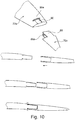
- Fig. 10 shows the projecting elements 88 projecting from the tip section 70e and received on the mainboard section 72a, it will be understood that additionally or alternatively the projecting elements 88 may project from the mainboard section to be received on the tip section in appropriate channels and grooves.
- Fig. 10 shows the receiving channels 90 defined on an external surface of the blade section with the projecting elements 88 having inwardly-facing gripper arms 88a
- the tip system connection may at least partially be defined on the interior of a blade, wherein at least one receiving channel and coupling groove is defined on an internal surface of a tip or mainboard section, and a corresponding projecting element comprises an outwardly-facing gripper arm.
- the gripper arms 88a and the coupling grooves 90a are shown as substantially straight elements, it will be understood that the arms 88a and/or grooves 90a may have any suitable profiles to provide for improved performance of the connection, e.g. a saw-tooth or dimpled profile. Additionally or alternatively, the projecting elements 88 and/or the receiving channels 90 may have appropriate profiling, e.g. to ensure that a minimum bond line distance is maintained between bond surfaces - corrugation, dimpling, etc.
- This embodiment provides a resilient connection system, which can provide for improved quality control, as the connection between sections can be confirmed by a visual inspection of the insertion of the gripper arms into the coupling grooves, and/or an aural indication of the coupling via a "click" sound formed by the snapping of the arms 88a into the coupling grooves 90a.
- Fig. 10 shows a single coupling groove 90a provided at the end of the receiving channel 90
- a plurality of coupling grooves may be provided along the length of the channel 90, wherein the length by which the projecting elements 88 are received within the channel may be varied.
- the grooves and arms may be arranged as a ratchet system within the channel, e.g. a one-way ratchet system.
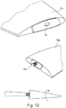
- a further embodiment of a tip section connection is shown.
- a pair of coupling elements 92 for example steel plates, project from an open end of a mainboard section 72b of a blade 10.
- a hollow tip section 70f may be positioned over the coupling elements 92, wherein apertures defined on the tip section 70f are aligned with corresponding apertures on the coupling elements 92.
- the tip section 70e may be mechanically attached to the coupling elements 92, e.g. via a nut-and-bolt connection 94.
- Appropriate other connections may also be used in addition or as an alternative to the nut-and-bolt connection, e.g. adhesive connections.
- connection system may be additionally or alternatively implemented on the opposite sections, e.g. the coupling elements 92 provided extending from a tip section.
- connection 94 may be provided as conductive metallic elements, they may be coupled with the lightning protection system of the blade 10, e.g. the connection 94 may be provided as a lightning receptor for the blade 10.
- This embodiment provides a relatively simple and straightforward connections system, which can easily be implemented in existing blade manufacturing systems.
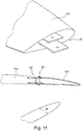
- a screw thread connection is provided between blade sections, wherein a threaded pin 96 projects from either a tip section or a mainboard section, wherein the threaded pin 96 is arranged to be received within a threaded hole 98 provided in the other of the sections, such that the tip section 70g may be relatively easily screwed onto the mainboard section 72c, for a robust connection between the elements.
- This connection may optionally be supplemented by adhesive applied at the interface between sections after the screwing operation has been completed, to improve the bonding between components.
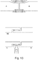
- blade sections A and B may be positioned adjacent one another, wherein a channel is defined at the interface between blade sections, and wherein a scarf joint may be formed between the sections by laying up fibre material in the channel and infusing the fibre material with a resin, e.g. vinyl ester resin, to bond the blade sections together.
- a resin e.g. vinyl ester resin
- spacers may be used at the interface between blade sections A and B, wherein the spacers act to set a bondline thickness between components.
- An adhesive or resin can be supplied to the interface to bond the sections together with an appropriate bondline thickness guaranteed.
- the joint may be formed directly between load-carrying structures of the two parts, e.g. between principal laminates of the two parts being integrated in the shell of said parts.
- Fig. 14 illustrates a wind turbine blade according to the invention and a method of manufacturing or assembling such a wind turbine blade according to the invention.
- the figure illustrates a wind turbine blade, which comprises a tip section 110 and a mainboard section 120, which are assembled at a joining section 130.
- the tip section 110 and the mainboard section 120 both comprise an aerodynamic shell, which includes a pressure side (or upwind side) shell part and a suction side (or downwind side) shell part.
- the figure also illustrates a schematic view of a cross-section of the mainboard section 120.
- the mainboard section comprises an aerodynamic shell with load-carrying principal laminates 121 integrated in the pressure side shell part and suction side shell part, respectively, the principal laminates forming spar caps.
- the aerodynamic shell may further as illustrated comprise load-carrying leading edge laminate(s) 122 and a load-carrying trailing edge laminate(s) 123.
- the blade may comprise sandwich constructions 124 comprising a sandwich core material between fibre skins and arranged between the various load-carrying structures 121, 122, 123.
- the blade further comprises shear webs 125 that are connected internally in the blade between the principal laminates 121.
- the tip section 110 is formed similar to the mainboard section, i.e. with load-carrying principal laminates 111 integrated in the aerodynamic shell and optionally a load-carrying leading edge laminate 112 and a load-carrying trailing edge laminate 113.
- the tip section 110 and the mainboard section 120 are as illustrated connected to each other at the joining section 130 via a first layup 140 or insert forming a first scarf joint connecting the load-carrying principal laminates 111, 121 of the tip section and the mainboard section, respectively, a leading edge layup 150 or insert forming a leading edge scarf joint connecting the load-carrying leading edge laminates 112, 122 of the tip section and the mainboard section, respectively, and a trailing edge layup 140 or insert forming a trailing edge scarf joint connecting the load-carrying trailing edge laminates 113, 123 of the tip section and the mainboard section, respectively.
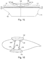
- Fig. 15 schematically shows a longitudinal cross-sectional view of a part of the blade.
- the tip section 110 as previously mentioned comprises a load-carrying principal laminate 111 and a shear web 115 having a shear web flange 117 being bonded to the principal laminate 111 via an adhesive bond line 116.
- the mainboard section 120 as previously mentioned comprises a load-carrying principal laminate 121 and a shear web 125 having a shear web flange 127 being bonded to the principal laminate 121 via an adhesive bond line 126.
- the tip section 110 is formed such that the load-carrying principal laminate 111 comprises a recess 118 at the end facing the joining section 130, wherein the recess 118 comprises a taper section 119, where a thickness of the principal laminate 111 is tapered towards said end of the tip section 110.
- the mainboard section 120 is formed such that the load-carrying principal laminate 121 comprises a recess 128 at the end facing the joining section 130, wherein the recess 128 comprises a taper section 129, where a thickness of the principal laminate 121 is tapered towards said end of the mainboard section 120.
- the scarf joint is formed by a layup 140 that is arranged in the recesses 118, 128 and which is arranged to abut the taper section 119 of the principal laminate 111 of the tip section 110 and the taper section 129 of the principal laminate 121 of the tip section 120. Thereby, the layup forms a first scarf joint part to the tip section 110 and a second scarf joint part to the mainboard section 120.
- Fig. 16 shows a cross-sectional view through the wind turbine blade.
- the figure merely illustrates that the recesses and the joining layups advantageously also may be tapered in the transverse direction of the blade.
- the taper sections ensure that a strong assembly is achieved without any stiffness transitions. Further, the method provides a simple method of applying the layup to assemble the wind turbine blade and at the same time achieving a smooth aerodynamic finish between the tip section and the mainboard section of the blade.
- the load-carrying laminates are formed by fibre-reinforced laminates that comprises a plurality of fibre-reinforcement layers, often comprising 10-50 or 20-50 fibre-reinforcement layers.
- the taper sections may be formed by arranging ends of the fibre-reinforcement layers in a tapered arrangement.
- the individual layers may be arranged as ply-drops such that a step-wise taper is achieved in order to form a stepped scarf joint surface, or the individual layers may be cut taperingly in order to form a smooth scarf joint surface.
- the taper sections may also be formed by a post-moulding operation, e.g. by grinding the end surface in order to form a taper section.
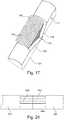
- Fig. 17 illustrates on embodiment for arranging the layup 140 in the recesses of the principal laminate 111, 121.
- the layup 140 comprises a number of fibre plies 141.
- the fibre plies 141 may be arranged individually to form the layup 140.
- the layup 140 may be provided as a pre-form comprising the fibre plies 14, e.g. connected via stiching, a tackifier or the like, or as a pre-cured element, which is adhesively bonded in the recesses.
- Figs. 15-17 have been illustrated for the main layup 140 only. However, it is clear that similar layups may be provided for attaching the leading edge laminates and the trailing edge laminates.
- Figs. 18 and 19 illustrate another way of assembling a wind turbine blade by connecting a tip section 210 and a mainboard section 220 at a joining section 230.
- a circumferentially extending attachment part 270 comprising a first layup 240, a second layup 250, and a third layup 260 is arranged in one step in order to connect the tip section 210 and the mainboard section 220.
- the circumferentially extending attachment part 270 is shaped such that the first layup is arranged in the recesses of the load-carrying principal laminates, the second layup 250 is arranged in recesses of the trailing edge laminates, and the third layup 260 is arranged in recesses of the leading edge laminates.
- the circumferentially extending attachment part 270 may partly or wholly be formed as a pre-shaped or pre-cured solid part. It may for instance be possible to provide the parts that connect the layups 240, 250, 260 as solid parts and let layups be provided as wet or dry fibre-reinforcement material. However, it is also possible to form the circumferentially extending attachment part 270 as a preform, where the layups 240, 250, 260 are arranged on a backing scrim or layer.
- the backing scrim may form the outer surface of the joining section, or alternatively an over-lamination may be carried out in order to form the outer surface.
- the backing scrim or over-lamination layer may for instance be made of a biaxial fibre-reinforcement layer.
- the circumferentially extending attachment may be formed as a single piece extending all the way around the blade, or alternatively it may as illustrated in Fig. 19 be formed by a first attachment part 270 and a second attachment part 270' for connecting the suction side and the pressure side of the blade, respectively.
- the tip section and the mainboard section have been connected by joining the load-carrying structures of the blade shells.
- it is also advantageous to connect the sandwich construction parts of the blades e.g. by adhesively bonding the sandwich constructions parts via a butt joint or a scarf joint.
- a tip section 310 and a mainboard section 320 are assembled by arranging layups 340 comprising a plurality of fibre plies 341 in recesses formed in the load-carrying principal laminates.
- the layup 340 may be provided as a wet layup, i.e. as pre-pregs, or it may be provided as dry fibre-reinforcement material, or a combination thereof. It may be necessary to add additional resin to the dry fibre material or pre-preg material, and said resin is subsequently cured or hardened in order to form a composite scarf joint.
- the resin may be applied by hand lamination or by forming a mould cavity, e.g. by arranging a vacuum foil across the recesses and layup and injecting a resin.
- a layup 440 in form of a pre-formed or premoulded solid piece is utilised to connect a tip section 410 and a mainboard section 420.
- the layup 440 is adhered to recesses of the load-carrying principal laminates by using an adhesive or alternatively or addition thereto a pre-wetted or saturated interface ply 445.
- the layup 440 may be held in place with a clamping device to ensure correct geometry and placement.
- a layup 540 in form of a pre-formed or premoulded solid piece is utilised to connect a tip section 510 and a mainboard section 520.
- the recesses of the load-carrying laminates (or alternatively the layup 540) are provided with spacers to provide a correct bondline thickness and channels between the recess and the layup 540.
- a cavity and channels are formed such that an adhesive may flow in said cavity.
- the adhesive may thus be injected into the cavity, e.g. from one end, and once a flow front reaches the other end, the injection may be stopped.
- the connections between the tip section and the mainboard section have been provided by a single set of recesses in load-carrying laminates and a single layup only.
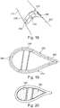
- Fig. 24 shows an example of such an embodiment illustrating a load-carrying principal laminate 611 of the tip section and a load-carrying principal laminate 621 of the mainboard section.
- connection between the tip section and the mainboard section may be formed partly by for instance direct butt joints and intermediate scarf joints formed via said layups 640, 642, 644.
Description
- The present invention relates to a tip system for a wind turbine blade, and associated methods of manufacture and assembly.
- To improve adaptability and manufacturability of wind turbine blades, blades can be provided in modular form, having for example a separate tip section from a mainboard and/or root section.
-
EP2634417A2 describes blade inserts that can be inserted between blade segments to make the resulting wind turbine blade longer. -
US2006/127222 describes the assembly of tip- and mainboard segments of wind turbine blades using connecting elements. -
US2010/132884 describes the assembly of blade segments by insertion of spar cap segments into each other and filling a resulting gap with adhesive. -
US2010/143062 describes a system for transporting and aligning a two-part wind turbine blade. - It is an object of the invention to provide improved designs of modular wind turbine blade designs.
- The invention relates to a method of manufacturing a wind turbine blade by joining a tip section of the blade and a mainboard section of the blade at a joining section, wherein
- the tip section comprises a first aerodynamic shell with a first load-carrying principal laminate integrated in the first aerodynamic shell, and
- the mainboard section comprising a second aerodynamic shell with a second load-carrying principal laminate integrated in the second aerodynamic shell, wherein
- the joining section is formed at a first end of the tip section and a second end of the mainboard section, wherein the method comprises the steps of:
- a) forming the tip section such that the first load-carrying principal laminate includes a first recess at the first end of the tip section, the first recess comprising a first taper section where a thickness of the first load-carrying principal laminate is tapered in thickness towards the first end of the tip section,
- b) forming the mainboard section such that the second load-carrying principal laminate includes a second recess at the second end of the mainboard section, the second recess comprising a second taper section where a thickness of the second load-carrying principal laminate is tapered in thickness towards the second end of the mainboard section,
- c) positioning the tip section and the mainboard section in longitudinal extension of each other such that the first recess and the second recess are aligned with each other at the joining section,
- d) arranging a first layup in the first recess and the second recess and
- e) joining said first layup to the first recess and the second recess such that a first scarf joint is formed between the first layup and the first taper section and the second taper section.
- Furthermore, joining step e) comprises wetting a fibre material with resin and curing said resin, said fibre material being dry fibre material infused with resin in an infusion process, such as a vacuum assisted infusion process.
- The present manufacturing method forms a robust and durable joint between the mainboard and tip sections of a modular wind turbine blade. The method introduces no extra loads or stresses in the load carrying structure, whereby the method provides a blade of a durability and quality equaling a common non-modular wind turbine blade. Further, the method provides the opportunity to shape the layup such that the intended aerodynamic surface may be achieved and a smooth transition from the tip section to the mainboard section may be achieved.
- In an embodiment of the invention the method further comprising the steps of
- a1) forming the tip section to also comprise, at the first end, a first leading edge recess in a first leading edge laminate and a first trailing edge recess in a first trailing edge laminate, the first leading edge recess comprising a first leading edge taper section where a thickness of the first leading edge laminate is tapered in thickness towards the first end and the first trailing edge recess comprising a first trailing edge taper section where a thickness of the first trailing edge laminate is tapered in thickness towards the first end,
- b1) forming the mainboard section to also comprise, at the second end, a second leading edge recess in a second leading edge laminate and a second trailing edge recess in a second trailing edge laminate, the second leading edge recess comprising a second leading edge taper section where a thickness of the second leading edge laminate is tapered in thickness towards the second end and the second trailing edge recess comprising a second trailing edge taper section where a thickness of the second trailing edge laminate is tapered in thickness towards the second end,
- d1) arranging a second layup in the first leading edge recess and in the second leading edge recess,
- d2) arranging a third layup in the first trailing edge recess and in the second trailing edge recess,
- e1) joining said second layup to the first leading edge recess and the second leading edge recess such that a second scarf joint is formed between the second layup and the first leading edge taper section and the second leading edge taper section
- e2) joining said third layup to the first trailing edge recess and the second trailing edge recess such that a third scarf joint is formed between the third layup and the first trailing edge taper section and the second trailing edge taper section.
- It may be beneficial to also join the mainboard- and tip sections at the leading edge and trailing edge of the blade using scarf joints in the local laminates to provide an advantageous structurally integrated wind turbine blade.
- In some embodiments it may be advantageous to have fibres from the principal load carrying laminates and/or from the leading edge- and trailing edge laminates of the tip section and mainboard section respectively protruding into the recesses and into the layups, whereby particularly strong integration of the lay ups with the mainboard - and tip sections may be achieved.
- For example, parts of fibre plies comprised in the principal load carrying laminate of the mainboard section may protrude at the taper section and into the air in the recess. These protruding fibre material can then be firmly integrated to a dry fibre layup, becoming an integral part of the layup, and after infusion with resin, a particularly strong connection may be formed. Of course such protruding fibre material may be provided in all tapering sections, partly pre-filling the recess.
- According to further embodiments of the invention the second layup and the third layup, is/are selected from the group consisting of a fibre material, a resin, a pre-formed part, an adhesive, a pre-preg material, a pre-cured element or any combination thereof.
- The layup material for attachment to the recesses in the laminate(s) of the tip section and of the mainboard section may be varied for different reasons, including price, production speed, ease of handling and complexity of arranging such layups.
- It may be beneficial to have one or more layups comprised in a preformed part. According to this embodiment, the preformed part may be arranged to attached to the recesses by gluing. The joint may be further strengthened, for example, by overlaminating, so that at least the principal main laminates of the tip- and mainboard sections, that is, the first principal main laminate and the second principal main laminate, and optionally also the leading edge laminates of the tip- and mainboard sections as well as the trailing edge laminates of the tip- and mainboard sections, are overlaminated at predesigned positions in the shell attachment element. Further, the overlamination may form the outer surface of the blade and thus provide a smooth aerodynamic surface.
- In an embodiment of the invention said first recess, said second recess, said first leading edge recess, said second leading edge recess, said first trailing edge recess and said second trailing edge recess overlap to form a single recess around the circumference of the tip section and the mainboard section.
- It may be advantageous to arrange one or more layups around the whole circumference of the two sections, respectively, to achieve a substantially continuous scarf joint around the circumference of the wind turbine blade.
- In further embodiments of the invention the joining steps e1) and e2), comprise
wetting a fibre material with resin and curing said resin, said fibre material being a pre-preg material and/or dry fibre material which then is infused with resin in an infusion process, such as a vacuum assisted infusion process. - A very versatile and advantageous embodiment is achieved when joining the tip section with the motherboard section using fibre material very similar or substantially identical to the fibre material already comprised in the principal load carrying laminates.
- The fibre material may be a pre-preg material which is cured, e.g. by heating, after arranging one or more layers in the recesses. The fibre material may also be plies of dry fibre, which, after arranging them in the recesses, are infused with resin and cured.
- When a vacuum assisted infusion process is used in these embodiments, a particularly advantageous embodiment has been achieved.
- It is also possible to combine pre-preg material with dry fibre material in the recesses.
- According to embodiments of the invention the joining steps e1) and e2), comprise gluing a pre-cured element or a pre-formed part to the first leading edge recess and to the second leading edge recess, and/or to the first trailing edge recess and to the second trailing edge recess. It may be advantageous to use pre-formed parts glued into the recesses. This may be comparatively easy to handle. Furthermore, the quality of the pre-formed part may be assessed prior to arranging them in the recesses, making this option advantageous with respect to quality control.
- It may also be possible to glue pre-formed parts into the recesses, still leaving som space for overlamination with dry fibre and resin and/or pre-preg material.
- According to embodiments of the invention the joining section has a length of 1 - 5 m in the longitudinal direction. To obtain a strong enough joint between the tip section and the mainboard section, the joining section may need to have a minimum length.
- According to embodiments of the invention the width of the joining section is between 0.5m and the total width of the blade from a leading edge to a trailing edge.
- According to further embodiments of the invention the taper has a depth to length ratio of between 1 to 30 and 1 to 2.
- According to an embodiment of the invention the ratio of the length of the tip section to the length of the mainboard section is between 1 to 8 and 1 to 1, preferably between 1 to 4 and 1 to 2.
- The invention also relates to a wind turbine blade formed by joining a tip section and a mainboard section by the method of claim 1.
- Embodiments of the invention will now be described, by way of example only, with reference to the accompanying drawings, in which:
-
Fig. 1 shows a wind turbine; -
Fig. 2 shows a schematic view of a wind turbine blade according to the invention; -
Fig. 3 shows a schematic view of an airfoil profile of the blade ofFig. 2 ; -
Fig. 4 shows a schematic view of the wind turbine blade ofFig. 2 , seen from above and from the side; and -
Figs. 5-24 illustrate various embodiments of tip section construction and tip system connections, according to the invention. - It will be understood that elements common to the different embodiments of the invention have been provided with the same reference numerals in the drawings.
-
Fig. 1 illustrates a conventional modernupwind wind turbine 2 according to the so-called "Danish concept" with atower 4, anacelle 6 and a rotor with a substantially horizontal rotor shaft. The rotor includes ahub 8 and threeblades 10 extending radially from thehub 8, each having ablade root 16 nearest the hub and ablade tip 14 furthest from thehub 8. The rotor has a radius denoted R. -
Fig. 2 shows a schematic view of awind turbine blade 10. Thewind turbine blade 10 has the shape of a conventional wind turbine blade and comprises aroot region 30 closest to the hub, a profiled or anairfoil region 34 furthest away from the hub and atransition region 32 between theroot region 30 and theairfoil region 34. Theblade 10 comprises aleading edge 18 facing the direction of rotation of theblade 10, when the blade is mounted on the hub, and a trailingedge 20 facing the opposite direction of the leadingedge 18. - The airfoil region 34 (also called the profiled region) has an ideal or almost ideal blade shape with respect to generating lift, whereas the
root region 30 due to structural considerations has a substantially circular or elliptical cross-section, which for instance makes it easier and safer to mount theblade 10 to the hub. The diameter (or the chord) of theroot region 30 is typically constant along theentire root area 30. Thetransition region 32 has a transitional profile 42 gradually changing from the circular orelliptical shape 40 of theroot region 30 to theairfoil profile 50 of theairfoil region 34. The chord length of thetransition region 32 typically increases substantially linearly with increasing distance r from the hub. - The
airfoil region 34 has anairfoil profile 50 with a chord extending between theleading edge 18 and the trailingedge 20 of theblade 10. The width of the chord decreases with increasing distance r from the hub. - It should be noted that the chords of different sections of the blade normally do not lie in a common plane, since the blade may be twisted and/or curved (i.e. pre-bent), thus providing the chord plane with a correspondingly twisted and/or curved course, this being most often the case in order to compensate for the local velocity of the blade being dependent on the radius from the hub.
-
Fig. 3 shows a schematic view of anairfoil profile 50 of a typical blade of a wind turbine depicted with the various parameters, which are typically used to define the geometrical shape of an airfoil. Theairfoil profile 50 has a pressure side 52 and asuction side 54, which during use - i.e. during rotation of the rotor - normally face towards the windward (or upwind) side and the leeward (or downwind) side, respectively. Theairfoil 50 has achord 60 with a chord length c extending between aleading edge 56 and a trailingedge 58 of the blade, known as the a chordwise direction. Theairfoil 50 has a thickness t, which is defined as the distance between the pressure side 52 and thesuction side 54. The thickness t of the airfoil varies along thechord 60. The deviation from a symmetrical profile is given by acamber line 62, which is a median line through theairfoil profile 50. The median line can be found by drawing inscribed circles from the leadingedge 56 to the trailingedge 58. The median line follows the centres of these inscribed circles and the deviation or distance from thechord 60 is called the camber f. The asymmetry can also be defined by use of parameters called the upper camber (or suction side camber) and lower camber (or pressure side camber), which are defined as the distances from thechord 60 and thesuction side 54 and pressure side 52, respectively. - Airfoil profiles are often characterised by the following parameters: the chord length c, the maximum camber f, the position df of the maximum camber f, the maximum airfoil thickness t, which is the largest diameter of the inscribed circles along the
median camber line 62, the position dt of the maximum thickness t, and a nose radius (not shown). These parameters are typically defined as ratios to the chord length c. Thus, a local relative blade thickness t/c is given as the ratio between the local maximum thickness t and the local chord length c. Further, the position dp of the maximum pressure side camber may be used as a design parameter, and of course also the position of the maximum suction side camber. -
Fig. 4 shows some other geometric parameters of the blade. The blade has a total blade length L, which is defined along the spanwise direction of the blade. As shown inFig. 2 , the root end is located at position r = 0, and the tip end located at r = L. Theshoulder 40 of the blade is located at a position r = Lw, and has a shoulder width W, which equals the chord length at theshoulder 40. The diameter of the root is defined as D. Further, the blade is provided with a prebend, which is defined as Δy, which corresponds to the out of plane deflection from apitch axis 22 of the blade. - The
wind turbine blade 10 generally comprises a shell made of fibre-reinforced polymer, and is typically made as a pressure side or upwind shell part 24 and a suction side ordownwind shell part 26 that are glued together alongbond lines 28 extending along the trailingedge 20 and the leadingedge 18 of theblade 10. Wind turbine blades are generally formed from fibre-reinforced plastics material, e.g. glass fibres and/or carbon fibres which are arranged in a mould and cured with a resin to form a solid structure. Modern wind turbine blades can often be in excess of 30 or 40 metres in length, having blade root diameters of several metres. Wind turbine blades are generally designed for relatively long lifetimes and to withstand considerable structural and dynamic loading. - With reference to
Fig. 2 , according to the invention the wind turbine blade is initially provided in at least two sections - at least a first section towards thetip end 14 of theblade 10, the tip end section indicated generally at 70, and at least a section comprising theroot end 16 of theblade 10, herein referred to as themainboard section 72. Theseparate sections wind turbine blade 10. - Preferably, the connection between the
sections Fig. 4 shows a pre-bent blade, it will be understood that no pre-bend is necessary in thetip section 70. Preferably, thetip section 70 comprises 1/6th to 1/4th of the total blade length. - Preferably, the
tip section 70 can be provided in a variety of different lengths and geometries, to allow for scalability of design. - With reference to
Fig. 5 , a first example of a tip system for a wind turbine blade is shown, showing atip section 70a looking from the root-end-side of the tip section towards thetip end 14. - In this embodiment, the
tip section 70a comprises three cores arranged to form aleading edge portion 71a, a trailingedge portion 71b, and amain laminate portion 71c. Thecore portions respective cores - The
cores - The
cores - The package, including the
cores tip section 70. The package can then be infused with a resin and cured to form thetip section 70. Preferably, the package is infused in a one-shot moulding process. The skin layers 74 are preferably infused, but it will be understood that portions of the surfaces of thecores - It will be understood that the
cores cores - This embodiment provides a relatively light-
weight tip section 70 which is relatively easy to manufacture, and may be suitable for automation. Thetip section 70 comprises no adhesive bond lines, and accordingly eliminates the possibility of bond line failure in thetip section 70, while reducing the weight of thetip section 70. Scalability may be provided by simply lengthening tools used to form thecore sections - A similar embodiment is indicated in
Fig. 6 , wherein atip section 70b is shown looking from the root-end-side of the tip section towards thetip end 14. - In this embodiment, in contrast to the embodiment of
Fig. 5 , threenon-hollow cores 76 are used to form thetip section 70b. As indicated inFig. 6 , thecores 76 may be formed from a solid material, may comprise a vacuumised solid to form a core structure (e.g. grains), and/or may comprise a foam core provided with a sealing foil (e.g. to prevent the ingress of resin). - The
cores 76 may be arranged in amould 78, preferably on top of at least one layer of fibre material, e.g.biax fibre material 80. Additional layers of fibre material may be provided adjacent thecores 76, e.g.unidirectional fibres 82 positioned beneath and on top of thecores 76 in the region of the main laminate portion of thetip section 70b. Further layers of fibre material (not shown) may be positioned on top of thecores 76 in themould 78, before themould 78 is closed and the fibre material infused with resin to form thetip section 70b. - Due to the use of
non-hollow cores 76, it may be possible to reduce or eliminate the use of pultruded reinforcement elements in thetip section 70b, and/or to reduce or eliminate the use of separate forming members to form the initial cores. - It will be understood that the features of the embodiments of
Figs. 5 and6 may be combined in a hybrid embodiment, e.g. wherein a portion of a tip section comprises non-hollow core sections and a portion comprises hollow core sections. - A further embodiment of a
tip section 70c according to the invention is shown inFig. 7 , wherein thetip section 70c comprises a central load-bearing section 82, preferably a load bearing beam or spar box, wherein non-load-carryingshape pieces 84 can be provided at the leading edge and/or the trailing edge of thetip section 70c. In the embodiment ofFig. 7 , thetip section 70c is formed wherein non-load-carryingshape pieces 84 are attached at the leading edge and trailing edge sides of the load-bearing section 82, such that a portion of the load-bearing section 82 is exposed on the surface of thetip section 70c. However, it will be understood that the non-load-carryingshape pieces 84 may alternatively be attached to the load-bearing section 82 wherein the non-load-carryingshape pieces 84 form a shell substantially around the entire load-bearing section 82, which is located in the interior of thetip section 70c. - The non-load-carrying
shape pieces 84 may be attached to the load-bearing section 82 using any suitable connection, e.g. adhesive bonding or bonding via resin infusion joint, mechanical connectors, e.g. bolting, riveting. - This embodiment provides several advantages. In a first aspect, the joint between components is not located at the leading edge or trailing edge, and accordingly may only experience loading due to aerodynamic forces. Furthermore, the load concentrations and load path can be easily calculated using the central load-
bearing section 82, which can easily be designed as appropriate. The load-bearing section 82 may be manufactured using any suitable manufacturing process, and can be relatively easily scaled as desired. - With reference to
Fig. 8 , an embodiment of a tip section connection according to the invention is illustrated for the embodiment ofFig. 7 . In this figure, the central load-bearing section 82 extends from thetip section 70c to provide aconnection member 82a, which can be received within an open end (not shown) of amainboard section 72 of asectional blade 10. Theconnection member 82a may be received within and connected to an appropriate portion of themainboard section 72, e.g. internal shear webs, a spar box or beam, etc. (as illustrated in outline inFig. 8 ). - An alternative embodiment of a tip section connection is illustrated in
Fig. 9 . In this embodiment, atip section 70d is provided wherein asection 86 of the external surface of the section, e.g. on the upwind or downwind side of the tip section, is longer in the spanwise direction towards theroot end 16 of theblade 10 than the opposite surface. E.g. theupwind side 86 may be 1-2 metres longer in the spanwise direction than the downwind side. - Similarly, in the mainboard section (not shown) the side on the opposed surface to the projecting
side 86 of thetip section 70d extends longer in the spanwise direction towards thetip end 14 of theblade 10. - This may be accomplished by extending the main laminate part of the corresponding projecting sections of the tip section and the mainboard section of the
blade 10 by corresponding distances to create a stepped transition between the sections at the interface between sections. - Accordingly, the
tip section 70d may be joined to the mainboard section by connecting the projecting portion of thetip section 70d with the projecting portion of the mainboard section. It will be understood that the sections may be joined using any suitable connection, as described above. Preferably, adhesive is applied along at least a portion of the interface between the sections, e.g. along bond lines provided at the edges of the surfaces of the shells of the projecting portions. Additionally or alternatively, the sections may be joined using overlamination between components. - A connection between the sections over a spanwise distance, e.g. at least 1-2 meters, can provide for a smooth transfer of loads between the blade sections. In addition, a relatively large glue area between sections can more easily distribute the shear forces involved in the structure. Furthermore, the configuration provides relatively easy access to glue surfaces before the
tip section 70d is joined with the mainboard section. - In this embodiment, the
mainboard section 72 may be provided with a relatively low pre-bend, wherein thetip section 70d may have a relatively larger pre-bend. - In
Fig. 10 , a further embodiment of a tip section connection is shown. In this embodiment, upper and lower projectingelements 88 project from opposite surfaces of thetip section 70e. The projectingelements 88 comprise inwardly-facinggripper arms 88a. Correspondingly, themainboard section 72a comprises receivingchannels 90 defined on external surfaces of themainboard section 72a at opposed sides of themainboard section 72a, the receivingchannels 90 extending in a substantially spanwise direction from the tip-end-side of themainboard section 72a. The length of the projectingelements 88 in the spanwise direction is substantially the same as the length of the receivingchannels 90 in the spanwise direction. - Coupling
grooves 90a are provided at the opposite ends of the receivingchannels 90 from the tip-end-side of themainboard section 72a, thecoupling grooves 90a having a greater depth than theadjacent receiving channels 90. Thecoupling grooves 90a extend in a direction substantially transverse to the spanwise direction. - For coupling of the
tip section 70e and themainboard section 72a, adhesive may be applied in the receivingchannels 90 and/or on the internal surfaces of the projectingelements 88. The projectingelements 88 are received within the receivingchannels 90 as thetip section 70e is moved towards themainboard section 72a, wherein the projectingelements 88 may be deflected as thegripper arms 88a contact the surface of the receivingchannels 90. Once thegripper arms 88a reach the end of the receivingchannels 90, thearms 88a snap into thecoupling grooves 90a at the end of thechannels 90 to provide a mechanical connection between thesections - The
tip section 70e can then be further secured to themainboard section 72a by the curing of suitable adhesive, and/or further mechanical connections, e.g. bolting, riveting, overlamination, etc. - Optionally, and as shown in
Fig. 10 , thecoupling grooves 90a may extend by a length which is greater than the width of the receivingchannels 90, for example so that a visual inspection of the presence of adhesive between thearms 88a and thegrooves 90a may be performed after coupling. - While in
Fig. 10 , adhesive is applied between the coupling sections of the tip system, additionally or alternatively, adhesive may be applied at the interface between thesections arms 88a are received within thegrooves 90a, e.g. through appropriate inlets (not shown) provided in the system, and/or through the sides of thecoupling grooves 90a (which may be wider than the projecting elements, as described above). - While
Fig. 10 shows the projectingelements 88 projecting from thetip section 70e and received on themainboard section 72a, it will be understood that additionally or alternatively the projectingelements 88 may project from the mainboard section to be received on the tip section in appropriate channels and grooves. - Additionally or alternatively, while the embodiment of
Fig. 10 shows the receivingchannels 90 defined on an external surface of the blade section with the projectingelements 88 having inwardly-facinggripper arms 88a, it will be understood that the tip system connection may at least partially be defined on the interior of a blade, wherein at least one receiving channel and coupling groove is defined on an internal surface of a tip or mainboard section, and a corresponding projecting element comprises an outwardly-facing gripper arm. - Furthermore, while the
gripper arms 88a and thecoupling grooves 90a are shown as substantially straight elements, it will be understood that thearms 88a and/orgrooves 90a may have any suitable profiles to provide for improved performance of the connection, e.g. a saw-tooth or dimpled profile. Additionally or alternatively, the projectingelements 88 and/or the receivingchannels 90 may have appropriate profiling, e.g. to ensure that a minimum bond line distance is maintained between bond surfaces - corrugation, dimpling, etc. - This embodiment provides a resilient connection system, which can provide for improved quality control, as the connection between sections can be confirmed by a visual inspection of the insertion of the gripper arms into the coupling grooves, and/or an aural indication of the coupling via a "click" sound formed by the snapping of the
arms 88a into thecoupling grooves 90a. - In addition, while the embodiment of
Fig. 10 shows asingle coupling groove 90a provided at the end of the receivingchannel 90, it will be understood that a plurality of coupling grooves may be provided along the length of thechannel 90, wherein the length by which the projectingelements 88 are received within the channel may be varied. In this regard, the grooves and arms may be arranged as a ratchet system within the channel, e.g. a one-way ratchet system. - With reference to
Fig. 11 , a further embodiment of a tip section connection is shown. In this embodiment, a pair ofcoupling elements 92, for example steel plates, project from an open end of amainboard section 72b of ablade 10. Ahollow tip section 70f may be positioned over thecoupling elements 92, wherein apertures defined on thetip section 70f are aligned with corresponding apertures on thecoupling elements 92. Accordingly, thetip section 70e may be mechanically attached to thecoupling elements 92, e.g. via a nut-and-bolt connection 94. Appropriate other connections may also be used in addition or as an alternative to the nut-and-bolt connection, e.g. adhesive connections. In addition, the steel plates ofFig. 11 may be replaced by any other material, e.g. composite material, fibre-reinforced composite material. It will be understood that the configuration of connection system may be additionally or alternatively implemented on the opposite sections, e.g. thecoupling elements 92 provided extending from a tip section. - In this case, as the
coupling elements 92 and theconnection 94 may be provided as conductive metallic elements, they may be coupled with the lightning protection system of theblade 10, e.g. theconnection 94 may be provided as a lightning receptor for theblade 10. - This embodiment provides a relatively simple and straightforward connections system, which can easily be implemented in existing blade manufacturing systems.
- With reference to
Fig. 12 , a further embodiment of a tip section connection is shown. In this embodiment, a screw thread connection is provided between blade sections, wherein a threadedpin 96 projects from either a tip section or a mainboard section, wherein the threadedpin 96 is arranged to be received within a threadedhole 98 provided in the other of the sections, such that thetip section 70g may be relatively easily screwed onto themainboard section 72c, for a robust connection between the elements. This connection may optionally be supplemented by adhesive applied at the interface between sections after the screwing operation has been completed, to improve the bonding between components. - With reference to
Fig. 13 , examples of possible tip connections are shown between blade sections A and B. In a first aspect, blade sections A and B may be positioned adjacent one another, wherein a channel is defined at the interface between blade sections, and wherein a scarf joint may be formed between the sections by laying up fibre material in the channel and infusing the fibre material with a resin, e.g. vinyl ester resin, to bond the blade sections together. - In a second aspect, spacers may be used at the interface between blade sections A and B, wherein the spacers act to set a bondline thickness between components. An adhesive or resin can be supplied to the interface to bond the sections together with an appropriate bondline thickness guaranteed.
- While the embodiments have been shown with a longitudinally extending bondline, it is also possible to utilise a scarf joint or a double-scarf joint to form the interface. The joint may be formed directly between load-carrying structures of the two parts, e.g. between principal laminates of the two parts being integrated in the shell of said parts.
- It will be understood that any of the features of the above embodiments may be used in combination with the features of any of the other embodiments presented above.
-
Fig. 14 illustrates a wind turbine blade according to the invention and a method of manufacturing or assembling such a wind turbine blade according to the invention. The figure illustrates a wind turbine blade, which comprises atip section 110 and amainboard section 120, which are assembled at a joiningsection 130. Thetip section 110 and themainboard section 120 both comprise an aerodynamic shell, which includes a pressure side (or upwind side) shell part and a suction side (or downwind side) shell part. - The figure also illustrates a schematic view of a cross-section of the
mainboard section 120. The mainboard section comprises an aerodynamic shell with load-carryingprincipal laminates 121 integrated in the pressure side shell part and suction side shell part, respectively, the principal laminates forming spar caps. The aerodynamic shell may further as illustrated comprise load-carrying leading edge laminate(s) 122 and a load-carrying trailing edge laminate(s) 123. Further, the blade may comprisesandwich constructions 124 comprising a sandwich core material between fibre skins and arranged between the various load-carryingstructures shear webs 125 that are connected internally in the blade between theprincipal laminates 121. - The
tip section 110 is formed similar to the mainboard section, i.e. with load-carryingprincipal laminates 111 integrated in the aerodynamic shell and optionally a load-carryingleading edge laminate 112 and a load-carrying trailing edge laminate 113. - The
tip section 110 and themainboard section 120 are as illustrated connected to each other at the joiningsection 130 via afirst layup 140 or insert forming a first scarf joint connecting the load-carryingprincipal laminates leading edge layup 150 or insert forming a leading edge scarf joint connecting the load-carryingleading edge laminates edge layup 140 or insert forming a trailing edge scarf joint connecting the load-carryingtrailing edge laminates 113, 123 of the tip section and the mainboard section, respectively. -
Fig. 15 schematically shows a longitudinal cross-sectional view of a part of the blade. Thetip section 110 as previously mentioned comprises a load-carryingprincipal laminate 111 and ashear web 115 having ashear web flange 117 being bonded to theprincipal laminate 111 via anadhesive bond line 116. Equivalently, themainboard section 120 as previously mentioned comprises a load-carryingprincipal laminate 121 and ashear web 125 having a shear web flange 127 being bonded to theprincipal laminate 121 via anadhesive bond line 126. - It is seen that the
tip section 110 is formed such that the load-carryingprincipal laminate 111 comprises arecess 118 at the end facing the joiningsection 130, wherein therecess 118 comprises ataper section 119, where a thickness of theprincipal laminate 111 is tapered towards said end of thetip section 110. Similarly, themainboard section 120 is formed such that the load-carryingprincipal laminate 121 comprises arecess 128 at the end facing the joiningsection 130, wherein therecess 128 comprises ataper section 129, where a thickness of theprincipal laminate 121 is tapered towards said end of themainboard section 120. - The scarf joint is formed by a
layup 140 that is arranged in therecesses taper section 119 of theprincipal laminate 111 of thetip section 110 and thetaper section 129 of theprincipal laminate 121 of thetip section 120. Thereby, the layup forms a first scarf joint part to thetip section 110 and a second scarf joint part to themainboard section 120. -
Fig. 16 shows a cross-sectional view through the wind turbine blade. In addition to the features shown inFigs. 14 and15 , the figure merely illustrates that the recesses and the joining layups advantageously also may be tapered in the transverse direction of the blade. - The taper sections ensure that a strong assembly is achieved without any stiffness transitions. Further, the method provides a simple method of applying the layup to assemble the wind turbine blade and at the same time achieving a smooth aerodynamic finish between the tip section and the mainboard section of the blade.
- In general, it is recognised that the load-carrying laminates are formed by fibre-reinforced laminates that comprises a plurality of fibre-reinforcement layers, often comprising 10-50 or 20-50 fibre-reinforcement layers. The taper sections may be formed by arranging ends of the fibre-reinforcement layers in a tapered arrangement. The individual layers may be arranged as ply-drops such that a step-wise taper is achieved in order to form a stepped scarf joint surface, or the individual layers may be cut taperingly in order to form a smooth scarf joint surface. The taper sections may also be formed by a post-moulding operation, e.g. by grinding the end surface in order to form a taper section.
-
Fig. 17 illustrates on embodiment for arranging thelayup 140 in the recesses of theprincipal laminate layup 140 comprises a number of fibre plies 141. The fibre plies 141 may be arranged individually to form thelayup 140. Alternatively, thelayup 140 may be provided as a pre-form comprising the fibre plies 14, e.g. connected via stiching, a tackifier or the like, or as a pre-cured element, which is adhesively bonded in the recesses. -
Figs. 15-17 have been illustrated for themain layup 140 only. However, it is clear that similar layups may be provided for attaching the leading edge laminates and the trailing edge laminates. -
Figs. 18 and 19 illustrate another way of assembling a wind turbine blade by connecting atip section 210 and amainboard section 220 at a joiningsection 230. In the illustrated method, a circumferentially extendingattachment part 270 comprising afirst layup 240, asecond layup 250, and athird layup 260 is arranged in one step in order to connect thetip section 210 and themainboard section 220. The circumferentially extendingattachment part 270 is shaped such that the first layup is arranged in the recesses of the load-carrying principal laminates, thesecond layup 250 is arranged in recesses of the trailing edge laminates, and thethird layup 260 is arranged in recesses of the leading edge laminates. - The circumferentially extending
attachment part 270 may partly or wholly be formed as a pre-shaped or pre-cured solid part. It may for instance be possible to provide the parts that connect thelayups attachment part 270 as a preform, where thelayups - The circumferentially extending attachment may be formed as a single piece extending all the way around the blade, or alternatively it may as illustrated in
Fig. 19 be formed by afirst attachment part 270 and a second attachment part 270' for connecting the suction side and the pressure side of the blade, respectively. - In the embodiments shown in
Fig. 14-19 , the tip section and the mainboard section have been connected by joining the load-carrying structures of the blade shells. However, it is also advantageous to connect the sandwich construction parts of the blades, e.g. by adhesively bonding the sandwich constructions parts via a butt joint or a scarf joint. However, it may in some circumstances be difficult to connect the sandwich construction parts. Therefore, it may be advantageous to close off the ends of the tip section and the mainboard section, respectively, by use of bulkheads. This may for instance as illustrated inFig. 20 be carried out by arranging a trailingedge bulkhead 380 and a trailingedge bulkhead 382. Due to the connection between the principal laminates of the tip section and the mainboard section, it is not necessary to provide a bulkhead between the shear webs. However, it is of course possible to provide an additional bulkhead between the shear webs or to provide a single bulkhead extending in the entire cross-section of the blade section. - As previously mentioned, it is possible to provide the layup and scarf joints in a number of different ways. In a first highly advantageous method illustrated schematically in
Fig. 21 , atip section 310 and amainboard section 320 are assembled by arranginglayups 340 comprising a plurality of fibre plies 341 in recesses formed in the load-carrying principal laminates. Thelayup 340 may be provided as a wet layup, i.e. as pre-pregs, or it may be provided as dry fibre-reinforcement material, or a combination thereof. It may be necessary to add additional resin to the dry fibre material or pre-preg material, and said resin is subsequently cured or hardened in order to form a composite scarf joint. The resin may be applied by hand lamination or by forming a mould cavity, e.g. by arranging a vacuum foil across the recesses and layup and injecting a resin. - In a second method illustrated in
Fig. 22 , alayup 440 in form of a pre-formed or premoulded solid piece is utilised to connect atip section 410 and amainboard section 420. Thelayup 440 is adhered to recesses of the load-carrying principal laminates by using an adhesive or alternatively or addition thereto a pre-wetted or saturatedinterface ply 445. Thelayup 440 may be held in place with a clamping device to ensure correct geometry and placement. - In a third method illustrated in
Fig. 23 , alayup 540 in form of a pre-formed or premoulded solid piece is utilised to connect atip section 510 and amainboard section 520. The recesses of the load-carrying laminates (or alternatively the layup 540) are provided with spacers to provide a correct bondline thickness and channels between the recess and thelayup 540. Thus, a cavity and channels are formed such that an adhesive may flow in said cavity. The adhesive may thus be injected into the cavity, e.g. from one end, and once a flow front reaches the other end, the injection may be stopped. - In the previously described embodiments, the connections between the tip section and the mainboard section have been provided by a single set of recesses in load-carrying laminates and a single layup only. However, it is also possible to establish the connection by providing a plurality of sets of recesses and mating layups, e.g. two or three, in the various load-carrying laminates.
Fig. 24 shows an example of such an embodiment illustrating a load-carryingprincipal laminate 611 of the tip section and a load-carryingprincipal laminate 621 of the mainboard section. In the shown embodiment, three longitudinally extending recesses are formed and aligned at the end section of theprincipal laminates first layup 640, asecond layup 642, andthird layup 644 are arranged in said recesses. Accordingly, the connection between the tip section and the mainboard section may be formed partly by for instance direct butt joints and intermediate scarf joints formed via saidlayups - The invention is not limited to the embodiments described herein, and may be modified or adapted without departing from the scope of the present invention, which is defined by the appended claims.
Claims (11)
- A method of manufacturing a wind turbine blade by joining a tip section (110) of the blade and a mainboard section (120) of the blade at a joining section (130), wherein- the tip section (110) comprises a first aerodynamic shell with a first load-carrying principal laminate (111) integrated in the first aerodynamic shell, and- the mainboard section (120) comprising a second aerodynamic shell with a second load-carrying principal laminate (121) integrated in the second aerodynamic shell, wherein- the joining section (130) is formed at a first end of the tip section and a second end of the mainboard section, wherein the method comprises the steps of:a) forming the tip section (110) such that the first load-carrying principal laminate (111) includes a first recess (118) at the first end of the tip section, the first recess comprising a first taper section (119) where a thickness of the first load-carrying principal laminate is tapered in thickness towards the first end of the tip section,b) forming the mainboard section (120) such that the second load-carrying principal laminate (121) includes a second recess (128) at the second end of the mainboard section, the second recess comprising a second taper section (129) where a thickness of the second load-carrying principal laminate is tapered in thickness towards the second end of the mainboard section,c) positioning the tip section (110) and the mainboard section (120) in longitudinal extension of each other such that the first recess and the second recess are aligned with each other at the joining section (130),d) arranging a first layup (140) in the first recess and the second recess ande) joining said first layup to the first recess and the second recess such that a first scarf joint is formed between the first layup and the first taper section and the second taper section, characterized in that joining step e) comprises wetting a fibre material with resin and curing said resin, said fibre material being dry fibre material infused with resin in an infusion process, such as a vacuum assisted infusion process.
- Method according to claim 1, said method further comprising the steps ofa1) forming the tip section to also comprise, at the first end, a first leading edge recess in a first leading edge laminate and a first trailing edge recess in a first trailing edge laminate, the first leading edge recess comprising a first leading edge taper section where a thickness of the first leading edge laminate is tapered in thickness towards the first end and the first trailing edge recess comprising a first trailing edge taper section where a thickness of the first trailing edge laminate is tapered in thickness towards the first end,b1) forming the mainboard section to also comprise, at the second end, a second leading edge recess in a second leading edge laminate and a second trailing edge recess in a second trailing edge laminate, the second leading edge recess comprising a second leading edge taper section where a thickness of the second leading edge laminate is tapered in thickness towards the second end and the second trailing edge recess comprising a second trailing edge taper section where a thickness of the second trailing edge laminate is tapered in thickness towards the second end,d1) arranging a second layup in the first leading edge recess and in the second leading edge recess,d2) arranging a third layup in the first trailing edge recess and in the second trailing edge recess,e1) joining said second layup to the first leading edge recess and the second leading edge recess such that a second scarf joint is formed between the second layup and the first leading edge taper section and the second leading edge taper section, ande2) joining said third layup to the first trailing edge recess and the second trailing edge recess such that a third scarf joint is formed between the third layup and the first trailing edge taper section and the second trailing edge taper section.
- Method according to claim 2, wherein the second layup and the third layup, is selected from the group consisting of
a fibre material, a resin, a pre-formed part, an adhesive, a pre-preg material, a pre-cured element or any combination thereof. - Method according to any of the claims 2 - 3, wherein said first recess, said second recess, said first leading edge recess, said second leading edge recess, said first trailing edge recess and said second trailing edge recess overlap to form a single recess around the circumference of the wind turbine blade.
- Method according to any of the claims 2 - 4, wherein joining steps e1) and e2), comprise
wetting a fibre material with resin and curing said resin, said fibre material being a pre-preg material and/or dry fibre material infused with resin in an infusion process, such as a vacuum assisted infusion process. - Method according to any of the claims 2 -4, wherein joining steps e1) and e2), comprise
gluing a pre-cured element or a pre-formed part to the first recess and the second recess, optionally to the first leading edge recess and to the second leading edge recess, and/or to the first trailing edge recess and to the second trailing edge recess. - Method according to any of the claims 1 - 6, wherein the joining section has a length of 1 - 5 m in the longitudinal direction.
- Method according to any of the claims 1 - 7, wherein the width of the joining section is between 0.5m and the total width of the blade from a leading edge to a trailing edge.
- Method according to any of the claims 1 - 8, wherein the taper has a depth to length ratio of between 1 to 30 and 1 to 2.
- Method according to any of the claims 1 - 9, wherein the ration of the length of the tip section to the length of the mainboard section is between 1 to 8 and 1 to 1, preferably between 1 to 4 and 1 to 2.
- A wind turbine blade formed by joining a tip section and a mainboard section by the method of claim 1.
Priority Applications (2)
| Application Number | Priority Date | Filing Date | Title |
|---|---|---|---|
| DK20151646.5T DK3708826T3 (en) | 2014-06-11 | 2015-06-11 | Tip system for a wind turbine blade |
| EP20151646.5A EP3708826B1 (en) | 2014-06-11 | 2015-06-11 | A tip system for a wind turbine blade |
Applications Claiming Priority (2)
| Application Number | Priority Date | Filing Date | Title |
|---|---|---|---|
| GBGB1410429.3A GB201410429D0 (en) | 2014-06-11 | 2014-06-11 | A tip system for a wild turbine blade |
| PCT/EP2015/063079 WO2015189338A1 (en) | 2014-06-11 | 2015-06-11 | A tip system for a wind turbine blade |
Related Child Applications (1)
| Application Number | Title | Priority Date | Filing Date |
|---|---|---|---|
| EP20151646.5A Division EP3708826B1 (en) | 2014-06-11 | 2015-06-11 | A tip system for a wind turbine blade |
Publications (2)
| Publication Number | Publication Date |
|---|---|
| EP3155258A1 EP3155258A1 (en) | 2017-04-19 |
| EP3155258B1 true EP3155258B1 (en) | 2020-01-15 |
Family
ID=51267087
Family Applications (2)
| Application Number | Title | Priority Date | Filing Date |
|---|---|---|---|
| EP15729795.3A Active EP3155258B1 (en) | 2014-06-11 | 2015-06-11 | A tip system for a wind turbine blade |
| EP20151646.5A Active EP3708826B1 (en) | 2014-06-11 | 2015-06-11 | A tip system for a wind turbine blade |
Family Applications After (1)
| Application Number | Title | Priority Date | Filing Date |
|---|---|---|---|
| EP20151646.5A Active EP3708826B1 (en) | 2014-06-11 | 2015-06-11 | A tip system for a wind turbine blade |
Country Status (9)
| Country | Link |
|---|---|
| US (1) | US20170122287A1 (en) |
| EP (2) | EP3155258B1 (en) |
| CN (2) | CN106662070B (en) |
| BR (1) | BR112016029061B1 (en) |
| CA (1) | CA2951777C (en) |
| DK (1) | DK3708826T3 (en) |
| GB (1) | GB201410429D0 (en) |
| MA (1) | MA50588A (en) |
| WO (1) | WO2015189338A1 (en) |
Families Citing this family (46)
| Publication number | Priority date | Publication date | Assignee | Title |
|---|---|---|---|---|
| GB201410429D0 (en) | 2014-06-11 | 2014-07-23 | Lm Wp Patent Holding As | A tip system for a wild turbine blade |
| EP3542051B1 (en) | 2016-11-21 | 2021-05-19 | LM Wind Power International Technology II ApS | A method and system for establishing a sectional or modular wind turbine blade and a mobile factory for joining sections of a wind turbine blade |
| EP3333416A1 (en) | 2016-12-07 | 2018-06-13 | LM WP Patent Holding A/S | A wind turbine blade comprising two blade parts and an aero-dynamic sleeve |
| CN106640558B (en) * | 2016-12-30 | 2019-04-12 | 北京金风科创风电设备有限公司 | Pitch bearing, blade, impeller and connection method for a wind turbine |
| US11098691B2 (en) | 2017-02-03 | 2021-08-24 | General Electric Company | Methods for manufacturing wind turbine rotor blades and components thereof |
| US10830206B2 (en) | 2017-02-03 | 2020-11-10 | General Electric Company | Methods for manufacturing wind turbine rotor blades and components thereof |
| US10495058B2 (en) * | 2017-02-21 | 2019-12-03 | General Electric Company | Joint assembly for rotor blade segments of a wind turbine |
| WO2018224106A1 (en) * | 2017-06-09 | 2018-12-13 | Vestas Wind Systems A/S | Modular wind turbine blades |
| CN107191324B (en) * | 2017-07-14 | 2019-01-08 | 连云港中复连众复合材料集团有限公司 | The preparation method of fan blade of wind generating set with aluminium point |
| US10544776B2 (en) * | 2017-07-27 | 2020-01-28 | General Electric Company | Injection method and device for connecting and repairing a shear web |
| JP6541742B2 (en) * | 2017-10-13 | 2019-07-10 | 三菱重工業株式会社 | Wind turbine blade repair method |
| US11390013B2 (en) | 2017-11-21 | 2022-07-19 | General Electric Company | Vacuum forming mold assembly and associated methods |
| US10920745B2 (en) | 2017-11-21 | 2021-02-16 | General Electric Company | Wind turbine rotor blade components and methods of manufacturing the same |
| US11040503B2 (en) | 2017-11-21 | 2021-06-22 | General Electric Company | Apparatus for manufacturing composite airfoils |
| US10821652B2 (en) | 2017-11-21 | 2020-11-03 | General Electric Company | Vacuum forming mold assembly and method for creating a vacuum forming mold assembly |
| US10865769B2 (en) | 2017-11-21 | 2020-12-15 | General Electric Company | Methods for manufacturing wind turbine rotor blade panels having printed grid structures |
| US11248582B2 (en) | 2017-11-21 | 2022-02-15 | General Electric Company | Multiple material combinations for printed reinforcement structures of rotor blades |
| US10913216B2 (en) | 2017-11-21 | 2021-02-09 | General Electric Company | Methods for manufacturing wind turbine rotor blade panels having printed grid structures |
| US10773464B2 (en) | 2017-11-21 | 2020-09-15 | General Electric Company | Method for manufacturing composite airfoils |
| US11668275B2 (en) | 2017-11-21 | 2023-06-06 | General Electric Company | Methods for manufacturing an outer skin of a rotor blade |
| CN108087191B (en) * | 2017-12-25 | 2020-01-31 | 江苏金风科技有限公司 | Sectional blade, method for connecting sectional blades and wind generating set |
| DE102018103344A1 (en) * | 2018-02-14 | 2019-08-14 | Wobben Properties Gmbh | Method for producing a split rotor blade and rotor blade |
| US10821696B2 (en) | 2018-03-26 | 2020-11-03 | General Electric Company | Methods for manufacturing flatback airfoils for wind turbine rotor blades |
| US11035339B2 (en) | 2018-03-26 | 2021-06-15 | General Electric Company | Shear web assembly interconnected with additive manufactured components |
| EP3784903A1 (en) * | 2018-04-23 | 2021-03-03 | Vestas Wind Systems A/S | Wind turbine blade assembly |
| EP3787871B1 (en) * | 2018-04-30 | 2023-08-16 | General Electric Company | Methods for manufacturing wind turbine rotor blades and components thereof |
| WO2019228599A1 (en) | 2018-05-31 | 2019-12-05 | Vestas Wind Systems A/S | Wind turbine blade leading edge fairing |
| EP3578807B1 (en) | 2018-06-08 | 2023-11-29 | Siemens Gamesa Renewable Energy A/S | Method of manufacturing wind turbine rotor blades |
| ES2949381T3 (en) | 2018-07-09 | 2023-09-28 | Vestas Wind Sys As | Improvements related to wind turbine blades |
| US11719222B2 (en) * | 2018-08-03 | 2023-08-08 | General Electric Company | Method of joining wind turbine rotor blade segments via structural members |
| US10794359B2 (en) * | 2018-09-24 | 2020-10-06 | General Electric Company | Jointed wind turbine blade with noise reduction tape |
| CN113165296B (en) * | 2018-10-18 | 2023-04-21 | 维斯塔斯风力系统有限公司 | Improvements relating to wind turbine blade manufacture |
| EP3894690A1 (en) * | 2018-12-11 | 2021-10-20 | General Electric Company | Beam structure for a segmented rotor blade having a transitioning shape |
| PT3712424T (en) * | 2019-03-21 | 2023-10-27 | Siemens Gamesa Renewable Energy As | Wind turbine blade and wind turbine |
| EP3747639A1 (en) * | 2019-06-07 | 2020-12-09 | Siemens Gamesa Renewable Energy A/S | Method for manufacturing a wind turbine blade and wind turbine blade |
| ES2951637T3 (en) * | 2019-10-09 | 2023-10-24 | Siemens Gamesa Renewable Energy As | Method for manufacturing a structural element of a wind turbine blade, method for manufacturing a wind turbine blade, structural element of a wind turbine blade and wind turbine blade |
| WO2021076097A1 (en) * | 2019-10-15 | 2021-04-22 | General Electric Company | Methods of joining blade components of wind turbine rotor blades using positioning elements |
| US11441545B2 (en) * | 2020-02-25 | 2022-09-13 | General Electric Company | Tungsten-based erosion-resistant leading edge protection cap for rotor blades |
| EP3892849B1 (en) * | 2020-04-06 | 2023-11-08 | Nordex Energy Spain, S.A.U. | Wind turbine rotor blade having a shear web |
| CN113958447B (en) * | 2021-11-10 | 2022-07-22 | 常州市宏发纵横新材料科技股份有限公司 | Modular wind power blade chord direction blocking connection structure |
| CN114183296B (en) * | 2021-11-10 | 2022-06-21 | 常州市宏发纵横新材料科技股份有限公司 | Wind-powered electricity generation blade spanwise piecemeal connection structure |
| EP4191052A1 (en) * | 2021-12-01 | 2023-06-07 | Siemens Gamesa Renewable Energy A/S | Wind turbine blade and method for manufacturing a wind turbine blade |
| EP4338938A1 (en) | 2022-05-09 | 2024-03-20 | Newtech Group Co., Ltd. | Modular blade connection structure, method, and tooling |
| CN114851581B (en) * | 2022-05-09 | 2022-11-25 | 新创碳谷集团有限公司 | Modular blade connecting structure, method and tool |
| EP4344866A1 (en) * | 2022-09-30 | 2024-04-03 | Siemens Gamesa Renewable Energy A/S | Resin joining portion for wind turbine blades |
| CN116039124B (en) * | 2023-04-03 | 2023-06-13 | 新创碳谷集团有限公司 | Integral molding tool and molding process for rear edge of modularized segmented blade |
Citations (13)
| Publication number | Priority date | Publication date | Assignee | Title |
|---|---|---|---|---|
| US4474536A (en) | 1980-04-09 | 1984-10-02 | Gougeon Brothers, Inc. | Wind turbine blade joint assembly and method of making wind turbine blades |
| US20060127222A1 (en) | 2002-08-02 | 2006-06-15 | Rainer Arelt | Method for producing a rotor blade, a corresponding rotor blade and a wind power plant |
| US20090162208A1 (en) | 2007-12-19 | 2009-06-25 | General Electric Company | Multi-segment wind turbine blade and method for assembling the same |
| EP2186622A1 (en) | 2008-11-13 | 2010-05-19 | The Boeing Company | Method for joining composite structural members and structural members made thereby |
| US20100132884A1 (en) | 2009-05-28 | 2010-06-03 | General Electric Company | Method for assembling jointed wind turbine blade |
| US20100135820A1 (en) | 2009-07-09 | 2010-06-03 | General Electric Wind & Energy Services | Wind blade spar cap laminate repair |
| US20100143062A1 (en) | 2009-05-04 | 2010-06-10 | Nicholas Joseph Tobergte | Apparatus and method for transporting and aligning wind turbine rotor blade |
| US20110142667A1 (en) | 2010-08-30 | 2011-06-16 | General Electric Company | Wind turbine rotor blade assembly having an access window and related methods |
| US20110229336A1 (en) | 2010-03-22 | 2011-09-22 | Vestas Wind Systems A/S | Method for manufacturing a blade spar for a wind turbine |
| WO2012004571A2 (en) | 2010-07-08 | 2012-01-12 | Blade Dynamics Limited | A wind turbine blade |
| US20120308396A1 (en) | 2010-02-10 | 2012-12-06 | Vestas Wind Systems A/S | Sectional blade |
| EP2634417A2 (en) | 2012-02-29 | 2013-09-04 | General Electric Company | Blade insert for a wind turbine rotor blade and related methods |
| WO2015189338A1 (en) | 2014-06-11 | 2015-12-17 | Lm Wp Patent Holding A/S | A tip system for a wind turbine blade |
Family Cites Families (10)
| Publication number | Priority date | Publication date | Assignee | Title |
|---|---|---|---|---|
| EP1486415A1 (en) * | 2003-06-12 | 2004-12-15 | SSP Technology A/S | Wind turbine blade and method of manufacturing a blade root |
| ES2319599B1 (en) * | 2007-01-08 | 2010-01-26 | Guillermo Petri Larrea | REVERSIBLE SECTIONING SYSTEM IN VARIOUS PARTS OF AEROGENERATING BLADES. |
| DE102010015392B4 (en) * | 2010-04-19 | 2019-07-25 | Aero-Dynamik-Consult Gmbh | Connecting element for a rotor blade of a wind turbine |
| EP2616671B1 (en) * | 2010-09-15 | 2017-07-26 | Vestas Wind Systems A/S | Wind turbine blade structures, lifting assemblies and methods of blade handling |
| GB2488099A (en) * | 2011-01-31 | 2012-08-22 | Vestas Wind Sys As | Modular wind turbine blade with both spar and foil sections forming aerodynamic profile |
| WO2012167788A2 (en) * | 2011-06-09 | 2012-12-13 | Pp Energy Aps | Lifting device for connecting two rotor blade segments of a wind turbine |
| CN103857902A (en) * | 2011-08-05 | 2014-06-11 | 泰克西斯先进技术及体系公司 | Aerogenerator blade tip segment and method of assembly |
| DK178203B1 (en) * | 2011-10-13 | 2015-08-10 | Gen Electric | Multi-segment wind turbine rotor blade with tensionably displaced connections and method for producing such rotor blade |
| DE102012217904A1 (en) * | 2012-10-01 | 2014-04-03 | Repower Systems Se | Fiber composite component and rotor blade |
| US9297357B2 (en) * | 2013-04-04 | 2016-03-29 | General Electric Company | Blade insert for a wind turbine rotor blade |
-
2014
- 2014-06-11 GB GBGB1410429.3A patent/GB201410429D0/en not_active Ceased
-
2015
- 2015-06-11 CN CN201580043009.3A patent/CN106662070B/en active Active
- 2015-06-11 MA MA050588A patent/MA50588A/en unknown
- 2015-06-11 BR BR112016029061-5A patent/BR112016029061B1/en active IP Right Grant
- 2015-06-11 EP EP15729795.3A patent/EP3155258B1/en active Active
- 2015-06-11 WO PCT/EP2015/063079 patent/WO2015189338A1/en active Application Filing
- 2015-06-11 US US15/317,229 patent/US20170122287A1/en active Pending
- 2015-06-11 CN CN202010789927.3A patent/CN111779625A/en active Pending
- 2015-06-11 DK DK20151646.5T patent/DK3708826T3/en active
- 2015-06-11 CA CA2951777A patent/CA2951777C/en active Active
- 2015-06-11 EP EP20151646.5A patent/EP3708826B1/en active Active
Patent Citations (14)
| Publication number | Priority date | Publication date | Assignee | Title |
|---|---|---|---|---|
| US4474536A (en) | 1980-04-09 | 1984-10-02 | Gougeon Brothers, Inc. | Wind turbine blade joint assembly and method of making wind turbine blades |
| US20060127222A1 (en) | 2002-08-02 | 2006-06-15 | Rainer Arelt | Method for producing a rotor blade, a corresponding rotor blade and a wind power plant |
| US20090162208A1 (en) | 2007-12-19 | 2009-06-25 | General Electric Company | Multi-segment wind turbine blade and method for assembling the same |
| EP2186622A1 (en) | 2008-11-13 | 2010-05-19 | The Boeing Company | Method for joining composite structural members and structural members made thereby |
| US20100143062A1 (en) | 2009-05-04 | 2010-06-10 | Nicholas Joseph Tobergte | Apparatus and method for transporting and aligning wind turbine rotor blade |
| US20100132884A1 (en) | 2009-05-28 | 2010-06-03 | General Electric Company | Method for assembling jointed wind turbine blade |
| US20100135820A1 (en) | 2009-07-09 | 2010-06-03 | General Electric Wind & Energy Services | Wind blade spar cap laminate repair |
| US20120308396A1 (en) | 2010-02-10 | 2012-12-06 | Vestas Wind Systems A/S | Sectional blade |
| US20110229336A1 (en) | 2010-03-22 | 2011-09-22 | Vestas Wind Systems A/S | Method for manufacturing a blade spar for a wind turbine |
| WO2012004571A2 (en) | 2010-07-08 | 2012-01-12 | Blade Dynamics Limited | A wind turbine blade |
| US20130129518A1 (en) | 2010-07-08 | 2013-05-23 | Blade Dynamics, Ltd. | Wind turbine blade |
| US20110142667A1 (en) | 2010-08-30 | 2011-06-16 | General Electric Company | Wind turbine rotor blade assembly having an access window and related methods |
| EP2634417A2 (en) | 2012-02-29 | 2013-09-04 | General Electric Company | Blade insert for a wind turbine rotor blade and related methods |
| WO2015189338A1 (en) | 2014-06-11 | 2015-12-17 | Lm Wp Patent Holding A/S | A tip system for a wind turbine blade |
Non-Patent Citations (6)
| Title |
|---|
| "Guide to Composites", GURIT BROCHURE, May 2009 (2009-05-01), XP055744449 |
| DAYTON A. GRIFFIN: "Blade System Design Studies Volume I: Composite Technologies for Large Wind Turbine Blades", July 2002 (2002-07-01), XP055605979 |
| EVER J. BARBERO: "INTRODUCTION TO COMPOSITE MATERIALS DESIGN", 1999, pages: 15 - 59, XP055744462 |
| F.C. CAMPBELL: "Structural Composite Materials", 2010, ASM INTERNATIONAL, pages: 1 - 612 |
| POVL BRONDSTED, ROGIER P.L. NIJSSEN: "Advances in wind turbine blade design and materials", 2013, WOODHEAD PUBLISHING, article POVL BRONDSTED, ROGIER P.L. NIJSSEN: "Chapter 6 - Fatigue as a design driver for composite wind turbine blades", pages: 175 - 182, XP055745216 |
| YOSIF GOLFMAN: "Hybrid Anisotropic Materials for Wind Power Turbine Blades", 2012, ISBN: 978-1-4398-6858-4, article "Chapter 4 - Manufacturing Technologies for Turbine Power Blades", pages: 89 - 106, XP055744458 |
Also Published As
| Publication number | Publication date |
|---|---|
| MA50588A (en) | 2021-04-21 |
| US20170122287A1 (en) | 2017-05-04 |
| EP3708826A1 (en) | 2020-09-16 |
| WO2015189338A1 (en) | 2015-12-17 |
| CA2951777C (en) | 2023-08-08 |
| GB201410429D0 (en) | 2014-07-23 |
| CN106662070B (en) | 2020-09-08 |
| BR112016029061A2 (en) | 2017-08-22 |
| CN106662070A (en) | 2017-05-10 |
| DK3708826T3 (en) | 2023-07-24 |
| EP3155258A1 (en) | 2017-04-19 |
| EP3708826B1 (en) | 2023-04-19 |
| CA2951777A1 (en) | 2015-12-17 |
| CN111779625A (en) | 2020-10-16 |
| BR112016029061B1 (en) | 2022-08-23 |
Similar Documents
| Publication | Publication Date | Title |
|---|---|---|
| EP3155258B1 (en) | A tip system for a wind turbine blade | |
| EP3027893B1 (en) | A wind turbine blade having a bond line adjacent a sandwich panel of the blade | |
| EP3488100B1 (en) | Wind turbine blade with flatback segment and related method | |
| US10337490B2 (en) | Structural component for a modular rotor blade | |
| US20140271217A1 (en) | Efficient wind turbine blade design and associated manufacturing methods using rectangular spars and segmented shear web | |
| EP3112668A1 (en) | Blade root section for a modular rotor blade and method of manufacturing same | |
| US10544776B2 (en) | Injection method and device for connecting and repairing a shear web | |
| US10947852B2 (en) | Tribrid wind turbine blade | |
| EP3065934B1 (en) | A joining method for wind turbine blade shells | |
| US10357931B2 (en) | System and method for manufacturing a wind turbine blade component | |
| EP3746279B1 (en) | Connection of mould parts | |
| US20210332790A1 (en) | A wind turbine blade with a plurality of shear webs | |
| WO2020083976A1 (en) | A wind turbine blade with multiple spar caps | |
| US20220178347A1 (en) | Wind turbine blade and method for producing a wind turbine blade | |
| US20220234319A1 (en) | Method for producing a wind turbine blade |
Legal Events
| Date | Code | Title | Description |
|---|---|---|---|
| STAA | Information on the status of an ep patent application or granted ep patent |
Free format text: STATUS: THE INTERNATIONAL PUBLICATION HAS BEEN MADE |
|
| PUAI | Public reference made under article 153(3) epc to a published international application that has entered the european phase |
Free format text: ORIGINAL CODE: 0009012 |
|
| STAA | Information on the status of an ep patent application or granted ep patent |
Free format text: STATUS: REQUEST FOR EXAMINATION WAS MADE |
|
| 17P | Request for examination filed |
Effective date: 20170105 |
|
| AK | Designated contracting states |
Kind code of ref document: A1 Designated state(s): AL AT BE BG CH CY CZ DE DK EE ES FI FR GB GR HR HU IE IS IT LI LT LU LV MC MK MT NL NO PL PT RO RS SE SI SK SM TR |
|
| AX | Request for extension of the european patent |
Extension state: BA ME |
|
| DAX | Request for extension of the european patent (deleted) | ||
| GRAP | Despatch of communication of intention to grant a patent |
Free format text: ORIGINAL CODE: EPIDOSNIGR1 |
|
| STAA | Information on the status of an ep patent application or granted ep patent |
Free format text: STATUS: GRANT OF PATENT IS INTENDED |
|
| INTG | Intention to grant announced |
Effective date: 20190805 |
|
| GRAS | Grant fee paid |
Free format text: ORIGINAL CODE: EPIDOSNIGR3 |
|
| GRAA | (expected) grant |
Free format text: ORIGINAL CODE: 0009210 |
|
| STAA | Information on the status of an ep patent application or granted ep patent |
Free format text: STATUS: THE PATENT HAS BEEN GRANTED |
|
| AK | Designated contracting states |
Kind code of ref document: B1 Designated state(s): AL AT BE BG CH CY CZ DE DK EE ES FI FR GB GR HR HU IE IS IT LI LT LU LV MC MK MT NL NO PL PT RO RS SE SI SK SM TR |
|
| REG | Reference to a national code |
Ref country code: CH Ref legal event code: EP Ref country code: GB Ref legal event code: FG4D |
|
| REG | Reference to a national code |
Ref country code: IE Ref legal event code: FG4D |
|
| REG | Reference to a national code |
Ref country code: DE Ref legal event code: R096 Ref document number: 602015045596 Country of ref document: DE |
|
| REG | Reference to a national code |
Ref country code: AT Ref legal event code: REF Ref document number: 1225366 Country of ref document: AT Kind code of ref document: T Effective date: 20200215 |
|
| REG | Reference to a national code |
Ref country code: NL Ref legal event code: FP |
|
| REG | Reference to a national code |
Ref country code: LT Ref legal event code: MG4D |
|
| PG25 | Lapsed in a contracting state [announced via postgrant information from national office to epo] |
Ref country code: RS Free format text: LAPSE BECAUSE OF FAILURE TO SUBMIT A TRANSLATION OF THE DESCRIPTION OR TO PAY THE FEE WITHIN THE PRESCRIBED TIME-LIMIT Effective date: 20200115 Ref country code: PT Free format text: LAPSE BECAUSE OF FAILURE TO SUBMIT A TRANSLATION OF THE DESCRIPTION OR TO PAY THE FEE WITHIN THE PRESCRIBED TIME-LIMIT Effective date: 20200607 Ref country code: NO Free format text: LAPSE BECAUSE OF FAILURE TO SUBMIT A TRANSLATION OF THE DESCRIPTION OR TO PAY THE FEE WITHIN THE PRESCRIBED TIME-LIMIT Effective date: 20200415 Ref country code: FI Free format text: LAPSE BECAUSE OF FAILURE TO SUBMIT A TRANSLATION OF THE DESCRIPTION OR TO PAY THE FEE WITHIN THE PRESCRIBED TIME-LIMIT Effective date: 20200115 |
|
| PG25 | Lapsed in a contracting state [announced via postgrant information from national office to epo] |
Ref country code: HR Free format text: LAPSE BECAUSE OF FAILURE TO SUBMIT A TRANSLATION OF THE DESCRIPTION OR TO PAY THE FEE WITHIN THE PRESCRIBED TIME-LIMIT Effective date: 20200115 Ref country code: GR Free format text: LAPSE BECAUSE OF FAILURE TO SUBMIT A TRANSLATION OF THE DESCRIPTION OR TO PAY THE FEE WITHIN THE PRESCRIBED TIME-LIMIT Effective date: 20200416 Ref country code: BG Free format text: LAPSE BECAUSE OF FAILURE TO SUBMIT A TRANSLATION OF THE DESCRIPTION OR TO PAY THE FEE WITHIN THE PRESCRIBED TIME-LIMIT Effective date: 20200415 Ref country code: LV Free format text: LAPSE BECAUSE OF FAILURE TO SUBMIT A TRANSLATION OF THE DESCRIPTION OR TO PAY THE FEE WITHIN THE PRESCRIBED TIME-LIMIT Effective date: 20200115 Ref country code: SE Free format text: LAPSE BECAUSE OF FAILURE TO SUBMIT A TRANSLATION OF THE DESCRIPTION OR TO PAY THE FEE WITHIN THE PRESCRIBED TIME-LIMIT Effective date: 20200115 Ref country code: IS Free format text: LAPSE BECAUSE OF FAILURE TO SUBMIT A TRANSLATION OF THE DESCRIPTION OR TO PAY THE FEE WITHIN THE PRESCRIBED TIME-LIMIT Effective date: 20200515 |
|
| REG | Reference to a national code |
Ref country code: DE Ref legal event code: R026 Ref document number: 602015045596 Country of ref document: DE |
|
| PLBI | Opposition filed |
Free format text: ORIGINAL CODE: 0009260 |
|
| PLBI | Opposition filed |
Free format text: ORIGINAL CODE: 0009260 |
|
| PLAX | Notice of opposition and request to file observation + time limit sent |
Free format text: ORIGINAL CODE: EPIDOSNOBS2 |
|
| PG25 | Lapsed in a contracting state [announced via postgrant information from national office to epo] |
Ref country code: CZ Free format text: LAPSE BECAUSE OF FAILURE TO SUBMIT A TRANSLATION OF THE DESCRIPTION OR TO PAY THE FEE WITHIN THE PRESCRIBED TIME-LIMIT Effective date: 20200115 Ref country code: RO Free format text: LAPSE BECAUSE OF FAILURE TO SUBMIT A TRANSLATION OF THE DESCRIPTION OR TO PAY THE FEE WITHIN THE PRESCRIBED TIME-LIMIT Effective date: 20200115 Ref country code: SK Free format text: LAPSE BECAUSE OF FAILURE TO SUBMIT A TRANSLATION OF THE DESCRIPTION OR TO PAY THE FEE WITHIN THE PRESCRIBED TIME-LIMIT Effective date: 20200115 Ref country code: DK Free format text: LAPSE BECAUSE OF FAILURE TO SUBMIT A TRANSLATION OF THE DESCRIPTION OR TO PAY THE FEE WITHIN THE PRESCRIBED TIME-LIMIT Effective date: 20200115 Ref country code: LT Free format text: LAPSE BECAUSE OF FAILURE TO SUBMIT A TRANSLATION OF THE DESCRIPTION OR TO PAY THE FEE WITHIN THE PRESCRIBED TIME-LIMIT Effective date: 20200115 Ref country code: ES Free format text: LAPSE BECAUSE OF FAILURE TO SUBMIT A TRANSLATION OF THE DESCRIPTION OR TO PAY THE FEE WITHIN THE PRESCRIBED TIME-LIMIT Effective date: 20200115 Ref country code: SM Free format text: LAPSE BECAUSE OF FAILURE TO SUBMIT A TRANSLATION OF THE DESCRIPTION OR TO PAY THE FEE WITHIN THE PRESCRIBED TIME-LIMIT Effective date: 20200115 Ref country code: EE Free format text: LAPSE BECAUSE OF FAILURE TO SUBMIT A TRANSLATION OF THE DESCRIPTION OR TO PAY THE FEE WITHIN THE PRESCRIBED TIME-LIMIT Effective date: 20200115 |
|
| REG | Reference to a national code |
Ref country code: AT Ref legal event code: MK05 Ref document number: 1225366 Country of ref document: AT Kind code of ref document: T Effective date: 20200115 |
|
| 26 | Opposition filed |
Opponent name: VESTAS WIND SYSTEMS A/S Effective date: 20201014 |
|
| 26 | Opposition filed |
Opponent name: SIEMENS GAMESA RENEWABLE ENERGY GMBH & CO. KG Effective date: 20201015 |
|
| PG25 | Lapsed in a contracting state [announced via postgrant information from national office to epo] |
Ref country code: AT Free format text: LAPSE BECAUSE OF FAILURE TO SUBMIT A TRANSLATION OF THE DESCRIPTION OR TO PAY THE FEE WITHIN THE PRESCRIBED TIME-LIMIT Effective date: 20200115 Ref country code: MC Free format text: LAPSE BECAUSE OF FAILURE TO SUBMIT A TRANSLATION OF THE DESCRIPTION OR TO PAY THE FEE WITHIN THE PRESCRIBED TIME-LIMIT Effective date: 20200115 Ref country code: IT Free format text: LAPSE BECAUSE OF FAILURE TO SUBMIT A TRANSLATION OF THE DESCRIPTION OR TO PAY THE FEE WITHIN THE PRESCRIBED TIME-LIMIT Effective date: 20200115 |
|
| REG | Reference to a national code |
Ref country code: CH Ref legal event code: PL |
|
| PG25 | Lapsed in a contracting state [announced via postgrant information from national office to epo] |
Ref country code: PL Free format text: LAPSE BECAUSE OF FAILURE TO SUBMIT A TRANSLATION OF THE DESCRIPTION OR TO PAY THE FEE WITHIN THE PRESCRIBED TIME-LIMIT Effective date: 20200115 Ref country code: SI Free format text: LAPSE BECAUSE OF FAILURE TO SUBMIT A TRANSLATION OF THE DESCRIPTION OR TO PAY THE FEE WITHIN THE PRESCRIBED TIME-LIMIT Effective date: 20200115 |
|
| PLBB | Reply of patent proprietor to notice(s) of opposition received |
Free format text: ORIGINAL CODE: EPIDOSNOBS3 |
|
| PG25 | Lapsed in a contracting state [announced via postgrant information from national office to epo] |
Ref country code: LU Free format text: LAPSE BECAUSE OF NON-PAYMENT OF DUE FEES Effective date: 20200611 |
|
| REG | Reference to a national code |
Ref country code: BE Ref legal event code: MM Effective date: 20200630 |
|
| PG25 | Lapsed in a contracting state [announced via postgrant information from national office to epo] |
Ref country code: IE Free format text: LAPSE BECAUSE OF NON-PAYMENT OF DUE FEES Effective date: 20200611 Ref country code: CH Free format text: LAPSE BECAUSE OF NON-PAYMENT OF DUE FEES Effective date: 20200630 Ref country code: LI Free format text: LAPSE BECAUSE OF NON-PAYMENT OF DUE FEES Effective date: 20200630 |
|
| PG25 | Lapsed in a contracting state [announced via postgrant information from national office to epo] |
Ref country code: BE Free format text: LAPSE BECAUSE OF NON-PAYMENT OF DUE FEES Effective date: 20200630 |
|
| VS25 | Lapsed in a validation state [announced via postgrant information from nat. office to epo] |
Ref country code: MA Free format text: LAPSE BECAUSE OF FAILURE TO SUBMIT A TRANSLATION OF THE DESCRIPTION OR TO PAY THE FEE WITHIN THE PRESCRIBED TIME-LIMIT Effective date: 20200115 |
|
| RAP2 | Party data changed (patent owner data changed or rights of a patent transferred) |
Owner name: LM WIND POWER A/S |
|
| PG25 | Lapsed in a contracting state [announced via postgrant information from national office to epo] |
Ref country code: TR Free format text: LAPSE BECAUSE OF FAILURE TO SUBMIT A TRANSLATION OF THE DESCRIPTION OR TO PAY THE FEE WITHIN THE PRESCRIBED TIME-LIMIT Effective date: 20200115 Ref country code: MT Free format text: LAPSE BECAUSE OF FAILURE TO SUBMIT A TRANSLATION OF THE DESCRIPTION OR TO PAY THE FEE WITHIN THE PRESCRIBED TIME-LIMIT Effective date: 20200115 Ref country code: CY Free format text: LAPSE BECAUSE OF FAILURE TO SUBMIT A TRANSLATION OF THE DESCRIPTION OR TO PAY THE FEE WITHIN THE PRESCRIBED TIME-LIMIT Effective date: 20200115 |
|
| RDAF | Communication despatched that patent is revoked |
Free format text: ORIGINAL CODE: EPIDOSNREV1 |
|
| PG25 | Lapsed in a contracting state [announced via postgrant information from national office to epo] |
Ref country code: MK Free format text: LAPSE BECAUSE OF FAILURE TO SUBMIT A TRANSLATION OF THE DESCRIPTION OR TO PAY THE FEE WITHIN THE PRESCRIBED TIME-LIMIT Effective date: 20200115 Ref country code: AL Free format text: LAPSE BECAUSE OF FAILURE TO SUBMIT A TRANSLATION OF THE DESCRIPTION OR TO PAY THE FEE WITHIN THE PRESCRIBED TIME-LIMIT Effective date: 20200115 |
|
| PLAB | Opposition data, opponent's data or that of the opponent's representative modified |
Free format text: ORIGINAL CODE: 0009299OPPO |
|
| APBM | Appeal reference recorded |
Free format text: ORIGINAL CODE: EPIDOSNREFNO |
|
| APBP | Date of receipt of notice of appeal recorded |
Free format text: ORIGINAL CODE: EPIDOSNNOA2O |
|
| APAH | Appeal reference modified |
Free format text: ORIGINAL CODE: EPIDOSCREFNO |
|
| R26 | Opposition filed (corrected) |
Opponent name: SIEMENS GAMESA RENEWABLE ENERGY GMBH & CO. KG Effective date: 20201015 |
|
| APBQ | Date of receipt of statement of grounds of appeal recorded |
Free format text: ORIGINAL CODE: EPIDOSNNOA3O |
|
| P01 | Opt-out of the competence of the unified patent court (upc) registered |
Effective date: 20230522 |
|
| PGFP | Annual fee paid to national office [announced via postgrant information from national office to epo] |
Ref country code: NL Payment date: 20230523 Year of fee payment: 9 Ref country code: FR Payment date: 20230523 Year of fee payment: 9 Ref country code: DE Payment date: 20230523 Year of fee payment: 9 |
|
| PGFP | Annual fee paid to national office [announced via postgrant information from national office to epo] |
Ref country code: GB Payment date: 20230523 Year of fee payment: 9 |