EP2634417A2 - Blade insert for a wind turbine rotor blade and related methods - Google Patents
Blade insert for a wind turbine rotor blade and related methods Download PDFInfo
- Publication number
- EP2634417A2 EP2634417A2 EP13154817.4A EP13154817A EP2634417A2 EP 2634417 A2 EP2634417 A2 EP 2634417A2 EP 13154817 A EP13154817 A EP 13154817A EP 2634417 A2 EP2634417 A2 EP 2634417A2
- Authority
- EP
- European Patent Office
- Prior art keywords
- blade
- segment
- insert
- rotor
- rotor blade
- Prior art date
- Legal status (The legal status is an assumption and is not a legal conclusion. Google has not performed a legal analysis and makes no representation as to the accuracy of the status listed.)
- Granted
Links
- 238000000034 method Methods 0.000 title description 15
- 230000008878 coupling Effects 0.000 claims abstract description 20
- 238000010168 coupling process Methods 0.000 claims abstract description 20
- 238000005859 coupling reaction Methods 0.000 claims abstract description 20
- 239000000463 material Substances 0.000 claims description 18
- 230000005484 gravity Effects 0.000 claims description 4
- 238000005520 cutting process Methods 0.000 description 15
- 230000007704 transition Effects 0.000 description 9
- 239000000853 adhesive Substances 0.000 description 5
- 230000001070 adhesive effect Effects 0.000 description 5
- 239000002131 composite material Substances 0.000 description 5
- 239000004917 carbon fiber Substances 0.000 description 4
- 239000003365 glass fiber Substances 0.000 description 4
- 210000001503 joint Anatomy 0.000 description 4
- 229920000049 Carbon (fiber) Polymers 0.000 description 3
- 230000004048 modification Effects 0.000 description 3
- 238000012986 modification Methods 0.000 description 3
- 230000008569 process Effects 0.000 description 3
- 238000005516 engineering process Methods 0.000 description 2
- 239000003733 fiber-reinforced composite Substances 0.000 description 2
- 230000006870 function Effects 0.000 description 2
- 238000004519 manufacturing process Methods 0.000 description 2
- 239000011159 matrix material Substances 0.000 description 2
- 230000002787 reinforcement Effects 0.000 description 2
- 239000011347 resin Substances 0.000 description 2
- 229920005989 resin Polymers 0.000 description 2
- 238000009420 retrofitting Methods 0.000 description 2
- 238000009756 wet lay-up Methods 0.000 description 2
- OKTJSMMVPCPJKN-UHFFFAOYSA-N Carbon Chemical compound [C] OKTJSMMVPCPJKN-UHFFFAOYSA-N 0.000 description 1
- 240000007182 Ochroma pyramidale Species 0.000 description 1
- 230000002411 adverse Effects 0.000 description 1
- 229910052799 carbon Inorganic materials 0.000 description 1
- 238000010276 construction Methods 0.000 description 1
- 239000011162 core material Substances 0.000 description 1
- 230000003247 decreasing effect Effects 0.000 description 1
- 239000004795 extruded polystyrene foam Substances 0.000 description 1
- 239000006260 foam Substances 0.000 description 1
- 239000011888 foil Substances 0.000 description 1
- 239000003562 lightweight material Substances 0.000 description 1
- 238000003754 machining Methods 0.000 description 1
- 230000013011 mating Effects 0.000 description 1
- VNWKTOKETHGBQD-UHFFFAOYSA-N methane Chemical compound C VNWKTOKETHGBQD-UHFFFAOYSA-N 0.000 description 1
- 238000010248 power generation Methods 0.000 description 1
- 238000010408 sweeping Methods 0.000 description 1
- XLYOFNOQVPJJNP-UHFFFAOYSA-N water Substances O XLYOFNOQVPJJNP-UHFFFAOYSA-N 0.000 description 1
- 239000002023 wood Substances 0.000 description 1
Images


Classifications
-
- F—MECHANICAL ENGINEERING; LIGHTING; HEATING; WEAPONS; BLASTING
- F03—MACHINES OR ENGINES FOR LIQUIDS; WIND, SPRING, OR WEIGHT MOTORS; PRODUCING MECHANICAL POWER OR A REACTIVE PROPULSIVE THRUST, NOT OTHERWISE PROVIDED FOR
- F03D—WIND MOTORS
- F03D1/00—Wind motors with rotation axis substantially parallel to the air flow entering the rotor
- F03D1/06—Rotors
- F03D1/0608—Rotors characterised by their aerodynamic shape
- F03D1/0633—Rotors characterised by their aerodynamic shape of the blades
-
- F—MECHANICAL ENGINEERING; LIGHTING; HEATING; WEAPONS; BLASTING
- F03—MACHINES OR ENGINES FOR LIQUIDS; WIND, SPRING, OR WEIGHT MOTORS; PRODUCING MECHANICAL POWER OR A REACTIVE PROPULSIVE THRUST, NOT OTHERWISE PROVIDED FOR
- F03D—WIND MOTORS
- F03D1/00—Wind motors with rotation axis substantially parallel to the air flow entering the rotor
- F03D1/06—Rotors
- F03D1/065—Rotors characterised by their construction elements
- F03D1/0675—Rotors characterised by their construction elements of the blades
-
- F—MECHANICAL ENGINEERING; LIGHTING; HEATING; WEAPONS; BLASTING
- F05—INDEXING SCHEMES RELATING TO ENGINES OR PUMPS IN VARIOUS SUBCLASSES OF CLASSES F01-F04
- F05B—INDEXING SCHEME RELATING TO WIND, SPRING, WEIGHT, INERTIA OR LIKE MOTORS, TO MACHINES OR ENGINES FOR LIQUIDS COVERED BY SUBCLASSES F03B, F03D AND F03G
- F05B2240/00—Components
- F05B2240/20—Rotors
- F05B2240/30—Characteristics of rotor blades, i.e. of any element transforming dynamic fluid energy to or from rotational energy and being attached to a rotor
- F05B2240/302—Segmented or sectional blades
-
- F—MECHANICAL ENGINEERING; LIGHTING; HEATING; WEAPONS; BLASTING
- F05—INDEXING SCHEMES RELATING TO ENGINES OR PUMPS IN VARIOUS SUBCLASSES OF CLASSES F01-F04
- F05B—INDEXING SCHEME RELATING TO WIND, SPRING, WEIGHT, INERTIA OR LIKE MOTORS, TO MACHINES OR ENGINES FOR LIQUIDS COVERED BY SUBCLASSES F03B, F03D AND F03G
- F05B2250/00—Geometry
- F05B2250/30—Arrangement of components
- F05B2250/31—Arrangement of components according to the direction of their main axis or their axis of rotation
- F05B2250/311—Arrangement of components according to the direction of their main axis or their axis of rotation the axes being in line
-
- F—MECHANICAL ENGINEERING; LIGHTING; HEATING; WEAPONS; BLASTING
- F05—INDEXING SCHEMES RELATING TO ENGINES OR PUMPS IN VARIOUS SUBCLASSES OF CLASSES F01-F04
- F05B—INDEXING SCHEME RELATING TO WIND, SPRING, WEIGHT, INERTIA OR LIKE MOTORS, TO MACHINES OR ENGINES FOR LIQUIDS COVERED BY SUBCLASSES F03B, F03D AND F03G
- F05B2250/00—Geometry
- F05B2250/70—Shape
- F05B2250/71—Shape curved
-
- F—MECHANICAL ENGINEERING; LIGHTING; HEATING; WEAPONS; BLASTING
- F05—INDEXING SCHEMES RELATING TO ENGINES OR PUMPS IN VARIOUS SUBCLASSES OF CLASSES F01-F04
- F05B—INDEXING SCHEME RELATING TO WIND, SPRING, WEIGHT, INERTIA OR LIKE MOTORS, TO MACHINES OR ENGINES FOR LIQUIDS COVERED BY SUBCLASSES F03B, F03D AND F03G
- F05B2260/00—Function
- F05B2260/30—Retaining components in desired mutual position
-
- Y—GENERAL TAGGING OF NEW TECHNOLOGICAL DEVELOPMENTS; GENERAL TAGGING OF CROSS-SECTIONAL TECHNOLOGIES SPANNING OVER SEVERAL SECTIONS OF THE IPC; TECHNICAL SUBJECTS COVERED BY FORMER USPC CROSS-REFERENCE ART COLLECTIONS [XRACs] AND DIGESTS
- Y02—TECHNOLOGIES OR APPLICATIONS FOR MITIGATION OR ADAPTATION AGAINST CLIMATE CHANGE
- Y02E—REDUCTION OF GREENHOUSE GAS [GHG] EMISSIONS, RELATED TO ENERGY GENERATION, TRANSMISSION OR DISTRIBUTION
- Y02E10/00—Energy generation through renewable energy sources
- Y02E10/70—Wind energy
- Y02E10/72—Wind turbines with rotation axis in wind direction
Definitions
- the present subject matter relates generally to wind turbines and, more particularly, to a blade insert for extending the length of a wind turbine rotor blade.
- a modem wind turbine typically includes a tower, generator, gearbox, nacelle, and one or more turbine blades.
- the turbine blades capture kinetic energy from wind using known foil principles and transmit the kinetic energy through rotational energy to turn a shaft coupling the rotor blades to a gearbox, or if a gearbox is not used, directly to the generator.
- the generator then converts the mechanical energy to electrical energy that may be deployed to a utility grid.
- a conventional tip extension is installed onto a rotor blade by cutting-off a portion of the blade at its tip and replacing such cut-off portion with the tip extension.
- the tip extension must be significantly longer than the actual increase in rotor blade length that can be achieved by installing the extension.
- a conventional tip extension may often need to have a length of almost half of the original span of the rotor blade to accommodate the increased loading on the blade. As such, due to their length, the costs of manufacturing and transporting conventional tip extensions can be prohibitively expensive.
- a blade insert that can be used to increase the span of a rotor blade by an amount generally corresponding to the overall length of the blade insert would be welcomed in the technology.
- the present subject is directed to a rotor blade assembly including a first blade segment having a first joint end and a second blade segment having a second joint end.
- the rotor blade assembly may include a blade insert having a first end coupled to the first joint end such that a first interface is defined between the blade insert and the first blade segment and a second end coupled to the second joint end such that a second interface is defined between the blade insert and the second blade segment.
- the blade insert may define a chord, wherein the chord at the first interface may be substantially equal to the chord at the second interface.
- the present subject matter is directed to a blade insert for coupling a first blade segment to a second blade segment.
- the blade insert may include an aerodynamic body extending between a first end configured to be coupled to the first blade segment and a second end configured to be coupled to the second blade segment.
- the aerodynamic body may include a pressure side and a suction side extending between a leading edge and a trailing edge.
- the aerodynamic body may define a chord, wherein the chord at the first end is substantially equal to the chord at the second end.
- the present subject is directed to a rotor blade assembly including a first blade segment having a first joint end and a second blade segment having a second joint end.
- the rotor blade assembly may include a blade insert having a first end coupled to the first joint end such that a first interface is defined between the blade insert and the first blade segment and a second end coupled to the second joint end such that a second interface is defined between the blade insert and the second blade segment.
- the stiffness of the blade insert may be greater than a stiffness of at least one of the first blade segment at the first joint end or the second blade segment at the second joint end.
- a pre-existing rotor blade may be divided into two blade segments, such as by cutting the pre-existing rotor blade at a specified location along its span.
- a blade insert may then be coupled between the blade segments in order to increase the overall length of the pre-existing rotor blade.
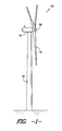
- FIG. 1 illustrates perspective view of one embodiment of a wind turbine 10.
- the wind turbine 10 includes a tower 12 with a nacelle 14 mounted thereon.
- a plurality of rotor blades 16 are mounted to a rotor hub 18, which is, in turn, connected to a main flange that turns a main rotor shaft.
- the wind turbine power generation and control components e.g., a turbine controller
- the wind turbine power generation and control components may be housed within the nacelle 14.
- FIG. 1 is provided for illustrative purposes only to place the present subject matter in an exemplary field of use.
- the present subject matter need not be limited to any particular type of wind turbine configuration.
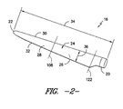
- the rotor blade 16 generally includes a blade root 20 configured for mounting the rotor blade 16 to the hub 18 of the wind turbine 10 ( FIG. 1 ) and a blade tip 22 disposed opposite the blade root 20.
- a body 24 of the rotor blade 16 may generally be configured to extend between the blade root 20 and the blade tip 22 and may serve as the outer casing/skin of the blade 16.
- the body 24 may define a substantially aerodynamic profile, such as by defining a symmetrical or cambered airfoil-shaped cross-section.
- the body 24 may include a pressure side 26 and a suction side 28 extending between a leading edge 30 and a trailing edge 32.
- the rotor blade 16 may have a span 34 defining the total length between the blade root 20 and the blade tip 22 and a chord 36 defining the total length between the leading edge 30 and the trialing edge 32.
- the chord 36 may vary in length with respect to the span 34 as the rotor blade 16 extends from the blade root 20 to the blade tip 22.
- the body 24 of the rotor blade 16 may be formed as a single, unitary component.
- the body 24 may be formed from a plurality of shell components.
- the body 24 may be manufactured from a first shell half generally defining the pressure side 26 of the rotor blade 16 and a second shell half generally defining the suction side 28 of the rotor blade 16, with the shell halves being secured to one another at the leading and trailing edges 30, 32 of the blade 16.
- the body 24 may generally be formed from any suitable material.
- the body 24 may be formed entirely from a laminate composite material, such as a carbon fiber reinforced laminate composite or a glass fiber reinforced laminate composite.
- one or more portions of the body 24 may be configured as a layered construction and may include a core material, formed from a lightweight material such as wood (e.g., balsa), foam (e.g., extruded polystyrene foam) or a combination of such materials, disposed between layers of laminate composite material.
- a core material formed from a lightweight material such as wood (e.g., balsa), foam (e.g., extruded polystyrene foam) or a combination of such materials, disposed between layers of laminate composite material.
- the rotor blade 16 may also include one or more longitudinally extending structural components configured to provide increased stiffness, buckling resistance and/or strength to the rotor blade 16.
- the rotor blade 16 may include one or more shear webs 38 ( FIG. 7 ) extending between corresponding spar caps 40 ( FIG. 7 ).
- the rotor blade 16 of the present disclosure may have any other suitable internal configuration.
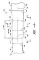
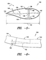
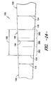
- FIGS. 3-6 one embodiment of a rotor blade assembly 100 is illustrated in accordance with aspects of the present subject matter.
- FIG. 3 illustrates a perspective, exploded view of the rotor blade assembly 100.
- FIG. 4 illustrates a partial, pressure side view of the rotor blade assembly 100.
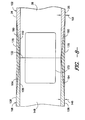
- FIG. 5 illustrates a cross-sectional view of the rotor blade assembly 100 shown in FIG. 4 taken about line 5-5.
- FIG. 6 illustrates a leading edge view of the rotor blade assembly 100 shown in FIG. 4 .
- the rotor blade assembly 100 may include a first blade segment 102, a second blade segment 104 and a blade insert 106 configured to be coupled between the first and second blade segments 102, 104.
- the rotor blade assembly 100 may be configured such that, when the first and second blade segments 102, 104 are coupled together via the blade insert 106, a complete rotor blade is formed.
- the first and second blade segments 102, 104 may be formed by dividing a pre-existing rotor blade 16 into two separate blade sections.
- the illustrated rotor blade 16 may be divided into the first and second blade segments 102, 104 by cutting the rotor blade 16 along a joint or cut line 108.
- the first blade segment 102 may generally comprise a root segment of the rotor blade 16 and may extend between the blade root 20 and a first joint end 110 formed at the cut line 108.
- the second blade segment 104 may comprise a tip segment of the rotor blade 16 and may extend between the blade tip 22 and a second joint end 112 formed at the cut line 108.
- each blade segment 102, 104 may generally define a chord 114, 116 corresponding to the total length of each segment between its leading and trailing edges 30, 32.
- the first blade segment 102 may define a first chord 114 and the second blade segment 104 may define a second chord 116, with the first chord 114 at the first joint end 110 being the same as or substantially the same as the second chord 116 at the second joint end 112.
- the total length of the first and second blade segments 102, 104 may generally correspond to the original span 34 of the rotor blade 16.
- the first blade segment 102 may define a first spanwise length 118 and the second blade segment 104 may define a second spanwise length 120 such that, when combined, the first and second spanwise lengths 118, 120 define a total segment length that is equal or substantially equal to the original span 34.
- total segment length will be used to refer to the combined length of the first and second spanwise lengths 118, 120.
- first and second spanwise lengths 118, 120 may generally vary depending on the location of the cut line 108.
- the location of the cut line 108 may be selected in order to provide spanwise lengths 118, 120 for the first and second blade segments 102, 104 that permit the blade insert 106 to be positioned along the length of the rotor blade assembly 100 at a location that enhances the overall performance of the assembly 100 while minimizing performance impacts (e.g., deflection, moment of inertia, etc.).
- the location of the cut line 108 along the rotor blade 16 may be selected such that the first spanwise length 118 ranges from about 40% to about 95% of the total segment length, such as from about 40% to about 80% of the total segment length or from about 50% to about 65% of the total segment length.
- the location of the cut line 108 may be selected such that the first spanwise length 118 is less then 40% of the total segment length or greater than 95% of the total segment length.
- the location of the cut line 108 may be selected such that the rotor blade 16 is divided outboard of its maximum chord location. For example, as shown in FIGS. 2 and 3 , the rotor blade 16 may be divided such that the maximum chord location 122 is included within the first blade segment 102. In a further embodiment, the location of the cut line 108 may be selected such that, when the blade insert 106 is coupled between the first and second blade segments 102, 104, a center of gravity 124 of the rotor blade assembly 100 is defined within the first blade segment 102.
- first and second blade segments 102, 104 need not be formed by cutting or otherwise dividing a pre-existing rotor blade 16 into two separate blade sections.
- first and second blade segments 102, 104 may be separately manufactured and assembled together with the blade insert 106 to form the disclosed rotor blade assembly 100.
- first blade segment and second blade segment need not be limited to a single, continuous blade segment.
- first blade segment 102 may be formed from a single, unitary blade segment extending between the blade root 20 and the first joint end 110 or the first blade segment 102 may be formed from two or more blade segments that, when coupled together, extend between blade root 20 and the first joint end 110.
- second blade segment 104 may be formed from a single, unitary blade segment extending between the second joint end 112 and the blade tip 22 or the second blade segment 104 may be formed from two or more blade segments that, when coupled together, extend between the second joint end 112 and the blade tip 22.
- the rotor blade assembly 100 may be divided into three or more blade segment, with a blade insert 106 being coupled between each pair of adjacent blade segments.
- the blade insert 106 of the rotor blade assembly 100 may generally comprise an elongated body 126 extending between a first end 128 and a second end 130.
- the blade insert 106 may be configured to be coupled between the first and second blade segments 102, 104 in order to form the rotor blade assembly 100.
- the first end 128 of the body 126 may be configured to be coupled to the joint end 110 of the first blade segment 102 such that a first interface 132 is defined between the blade insert 106 and the first blade segment 102.
- the second end 130 of the body 126 may be configured to be coupled to the joint end 112 of the second blade segment 104 such that a second interface 134 is defined between the blade insert 106 and the second blade segment 104.
- the body 126 of the blade insert 106 may also be configured to define a substantially aerodynamic profile, such as by defining a symmetric or cambered airfoil-shaped cross-section.
- the body 126 may include a pressure side 136 and a suction side 138 extending between a leading edge 140 and a trailing edge 142.
- the body 126 may also define a chord 144 corresponding to the overall length of the blade insert 106 between its leading and trailing edges 140, 142.
- the blade insert 106 may also include the same or similar internal structural components as the first and second blade segments 102, 104.
- the blade insert 106 may include a pair of longitudinally extending spar caps 146 configured to be aligned with the longitudinally extending spar caps 40 ( FIG. 7 ) of the blade segments 102, 104.
- the blade insert 106 may also include one or more shear webs 148 extending between the spar caps 146 that generally correspond to the shear web(s) 38 of the blade segments 102, 104.
- the blade insert 106 may include internal structural components that differ from the internal structural components of the blade segments 102, 104.
- the cross-section of the blade insert 106 at its first and second ends 128, 130 may generally be configured to correspond to or otherwise match the cross-sections of the first and second blade segments 102, 104 at their joint ends 110, 112.
- the cross-section of the insert body 126 at the first interface 132 may be the same as or substantially the same as the cross-section of the body 126 at the second interface 134.
- the chord 144 of the blade insert 106 at the first interface 132 may be the same as or substantially the same as the chord 144 at the second interface 134.
- the aerodynamic profile/shape of the blade insert 106 at the first interface 132 may be the same as or substantially the same as the aerodynamic profile/shape of the blade insert 106 at the second interface 134.
- a smooth, substantially continuous aerodynamic surface may be defined across the first and second interfaces 132, 134.
- the blade insert 106 may be configured to define a constant or varied cross-section between the first and second interfaces 132, 134.
- the blade insert 106 may be configured such that the body 126 defines a constant or substantially constant cross-section between the first and second interfaces 132, 134 (e.g., by defining both a substantially constant chord 144 and aerodynamic profile/shape between the first and second interfaces 132, 134).
- the chord 144 and/or aerodynamic profile/shape of the blade insert 106 may be varied between the first and second interfaces 132, 134.
- the blade insert 106 may also define a body thickness 149.
- a body thickness 149 may be defined between the inner and outer surfaces of the body 126 of the blade insert 106.
- the first and second blade segments 102, 104 may also define a body thickness 151.
- the first blade segment 102 may define a body thickness 151 between its inner and outer surfaces.
- the body thickness 149 of the blade insert 106 may be the same as or substantially the same as the body thickness 151 of the first and/or second blade segments at their joint ends 110, 112.
- the location of the cut line 108 may be selected so as to correspond to the location along the span 34 of the blade 16 at which its body thickness 151 is equal or substantially equal to the body thickness 149 of the blade insert 106.
- the body thickness 149 of the blade insert 106 may differ from the body thickness 151 of the first and/or second blade segments 102, 104 at its(their) joint ends 110, 112.
- the body thickness 149 of the blade insert 106 may be less than the body thickness 151 of both the first and second blade segments 102, 104 at their joint ends 110, 112.
- the body 126 of the blade insert 106 may also define a spanwise length 150 along a longitudinal axis 152 extending between its first and second ends 128, 130.
- the spanwise length 150 of the body 126 may be selected to provide the rotor blade assembly 100 increased efficiency (i.e., due to the overall increase in span) while taking into consideration relevant performance factors and/or operating conditions, such as the potential increases in deflection, thrust and/or torque that may result from the increased span.
- the spanwise length 150 of the blade insert 106 may range from about 1 meter (m) to about 20 meters, such as from about 3 m to about 12 m or from about 5 m to about 8 m and all other subranges therbetween.
- the blade insert 106 may be configured such that its length 150 is less than 1 m or greater than 20 meters. Additionally, in several embodiments, at least a portion of the blade insert 106 may be twisted about its longitudinal axis 152 ( FIGS. 4 and 6 ). For example, as shown in FIG. 5 , in one embodiment, the body 126 of the blade insert 106 may be twisted about its longitudinal axis 152 (e.g., in the direction of arrow 154) such that the orientation of the chord 144 at the first interface 132 differs from the orientation of the chord 144 at the second interface 134 by a twist angle 156. Such twisting may allow for the angle of attack of the rotor blade assembly 100 to be optimized, thereby increased its overall performance.
- the blade insert 106 may be curved relative to its longitudinal axis 152.
- the body 126 of the blade insert 106 may be curved relative to its longitudinal axis 152 such that the blade insert 106 defines an amount of pre-bend 158 between the first and second interfaces 132, 134.
- pre-bend 158 may be utilized to angle the rotor blade assembly 100 away from the tower 12 of a wind turbine 10 ( FIG. 1 ), thereby increasing the tower clearance and decreasing the likelihood of a tower strike.
- the blade insert 106 may also be curved or swept in the chordwise direction (i.e., the direction extending between the leading and trailing edges 140, 142 of the blade insert 102).
- the blade insert 106 may be swept such that a sweep angle 190 is defined between the longitudinal axis 152 of the blade insert 106 and the longitudinal axis of the first blade segment 102.
- Such sweeping of the blade insert 106 may be utilized to lower the pitching or torque load on the pitch system of the rotor blade assembly 100 or to help reduce overall loading on the wind turbine.
- the blade insert 106 may also be configured to include various other aerodynamic features (not shown).
- the blade insert 106 may include one or more spoilers, vortex generators and/or other aerodynamic surface features.
- the blade insert 106 may include one or more auxiliary airfoils mounted to the body 126.
- the blade insert 106 may generally be formed from any suitable material(s), such as by being formed from the same material(s) used to form the first and second blade segments 102, 104. However, in several embodiments, it may be desirable to form at least a portion of the blade insert 106 from a material(s) having a greater stiffness (e.g., a greater flexural rigidity) than the material(s) used to form the first and second blade segments 102, 104.
- a material(s) having a greater stiffness e.g., a greater flexural rigidity
- one or more of the spar caps 146 of the blade insert 106 may be formed from a material(s) having a greater stiffness than the material(s) used to form the first and second blade segments 102, 104, such as by forming the spar cap(s) 146 from a fiber-reinforced composite material(s) (e.g., a carbon or glass fiber reinforced composite) that has a greater stiffness than the fiber-reinforced composite material(s) used to form the blade segments 102, 104.
- the stiffness of the blade insert 106 may be configured to be greater than the stiffness of the first blade segment 102 at its joint end 110 and/or the stiffness of the second blade segment 104 at its joint end 112. Such increased stiffness may generally increase the rigidity of the rotor blade assembly 100 and may also decrease the tip deflection of the assembly 100.
- the material(s) and/or configuration of the blade insert 106 may be designed such that the insert 106 has a constant or substantially constant stiffness or flexural rigidity (EI) along its length 150.
- the blade insert 106 may be designed such that its flexural rigidity is substantially equal to the flexural rigidity of the first blade segment 102 at its joint end 110 and/or the second blade segment 104 at its joint end 112.
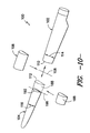
- FIGS. 7 and 8 illustrate one embodiment of an attachment means/method that may be utilized to attach the blade insert 106 to the joint ends 110, 112 of the first and second blade segments 102, 104.
- FIG. 7 illustrates a partial, perspective view of the joint end 110 of the first blade segment 102 and the first end 128 of the blade insert 106.
- FIG. 8 illustrates a cross-sectional view of the blade segment 102 and blade insert 106 shown in FIG. 7 after such components have been assembled together. It should be appreciated that, although FIGS.
- the blade insert 106 may be coupled to the first blade segment 102 by forming a scarf joint at the first interface 132.
- one or more tapered or scarfed sections 160, 162, 164, 166 may be formed along the outer perimeter of the first blade segment 102 at its joint end 110 and along the outer perimeter of the blade insert 106 at its first end 128.
- FIG. 1 For example, as particularly shown in FIG. 1
- scarfed sections 160, 162 may be formed at the first joint end 110 along the pressure and/or suction sides 26, 28 of the first blade segment 102, such as by forming a scarfed section 160 at a spar cap location on the pressure and/or suction sides 26, 28 of the first joint end 110 (e.g., by forming the scarfed section(s) 160 so as to be aligned longitudinally with each spar cap 40 of the blade segment 102) and/or by forming a scarfed section 162 at a trailing edge location on the pressure and/or suction sides 26, 28 of the first joint end 110 (e.g., by forming the scarfed section(s) 162 at a location substantially adjacent to the trailing edge 32 of the blade segment 102).
- corresponding scarfed sections 164, 166 may also be formed at the first end 128 of the blade insert 106, such as by forming a scarfed section 164 at a spar cap location on the pressure and/or suction sides 136, 138 of the first end 128 that corresponds to the scarfed section(s) 160 formed in the blade segment 102 and/or by forming a scarfed section 166 at a trailing edge location on the pressure and/or suction sides 136, 138 of the first end 128 that corresponds to the scarfed section(s) 162 formed in the blade segment 102.
- the scarfed section(s) 160, 162 formed at the joint end 110 of the blade segment 102 may be aligned with the scarfed section(s) 164, 166 formed at the end 128 of the blade insert 106 when the blade segment 102 and blade insert 106 are assembled together.
- the blade segment 110 and blade insert 106 may generally include any number of scarfed sections formed at any suitable location along the outer circumference of the ends 110, 128 of such components.
- the blade segment 102 and the blade insert 106 may be scarfed around the entire outer circumference of their ends 110, 128.
- the scarfed sections 160, 162, 164, 166 may generally be formed using any suitable manufacturing process known in the art. For example, in several embodiments, a grinding, cutting or other machining process may be used to remove material along the outer circumference of the blade segment 102 and the blade insert 106 such that each scarfed section 160, 162, 164, 166 tapers from a transition point 168 to the end 110, 128 of the blade segment 102 or blade insert 106.
- each tapered coupling 170 may be secured across the interface 132 defined between the blade segment 102 and the blade insert 106 so as to fill the area defined by the aligned scarfed sections 106, 162, 164.
- each tapered coupling 170 may comprise a pre-fabricated component configured to be separately secured within each pair of aligned scarfed sections 160, 162, 164, 166, such as by securing each tapered coupling 170 within each pair of aligned scarfed sections 160, 162, 164, 166 using suitable adhesives and/or mechanical fasteners (e.g., bolts, screws, pins, rivets, brackets and/or the like).
- suitable adhesives and/or mechanical fasteners e.g., bolts, screws, pins, rivets, brackets and/or the like.
- each tapered coupling 170 may be formed or otherwise built-up within each pair of aligned scarfed sections 160, 162, 164, 166.
- each tapered coupling 170 may be formed using a wet lay-up process, wherein a plurality of plies (including a reinforcement material such as glass or carbon fibers) are positioned across and/or within the aligned scarfed sections 160, 162, 164, 166 and a resin or other suitable matrix material is rolled over or otherwise applied to the surface of the plies and allowed to cure.
- plies including a reinforcement material such as glass or carbon fibers
- the rotor blade assembly 100 may also include various other structural components to enhance the strength of the joints formed between the blade segments 102, 104 and the blade insert 106.
- a leading edge insert 172 may be installed across the first interface 132 and/or the second interface 134 at the leading edges 30, 140 of the blade segment(s) 102, 104 and the blade insert 106.
- the leading edge insert 172 may define a curved profile generally corresponding to the curved profiles of the leading edges 30, 140 of the blade segment(s) 102, 104 and the blade insert 106.
- leading edge insert 172 may be secured across the first interface 132 and/or the second interface 134 by coupling the insert 172 to the inner surfaces of the blade segments 102, 104 and the blade insert 106 using suitable adhesives and/or mechanical fasteners.
- the rotor blade assembly 100 may also include one or more shear web couplings 174 configured to be secured to the shear webs 38, 148 of blade segments 102, 104 and the blade insert 106.
- first and second shear web couplings 174 may be secured to each side of the shear webs 38, 148 (e.g., using a suitable adhesive and/or mechanical fasteners) so as to extend across the first and/or second interface 132, 134.
- FIG. 9 illustrates a cross-sectional view of one embodiment of a doubler joint that may be formed at the interfaces 132, 134 defined between the blade insert 106 and the first and second blade segments 102, 104. Similar to the embodiment described above, it should be appreciated that, although FIG.
- one or more outer doublers 176 may be secured to an outer surface 178 of the blade segment 102 and an outer surface 180 of the blade insert 106 so as to extend across the first interface 132, such as by securing one or more outer doublers 176 across the interface 132 on the suction sides 28, 138 of the blade segment 102 and the blade insert 106 and/or by securing one or more outer doublers 176 across the interface 132 on the pressure sides 26, 138 of the blade segment 102 and the blade insert 106.
- the outer doublers 176 may generally be positioned at any suitable location around the outer circumference of the interface 132.
- the outer doublers 176 may be secured across the interface 132 at a spar cap location of the blade segment 102 and the blade insert 106 such that the outer doublers 176 are longitudinally aligned with the spar caps 40, 146.
- one or more inner doublers 182 may be secured to an inner surface 184 of the blade segment 102 and an inner surface 186 of the blade insert 106 so as to extend across the first interface 132, such as by securing one or more inner doublers 182 across the interface 132 on the suction sides 28, 138 of the blade segment 102 and the blade insert 106 and/or by securing one or more inner doublers 182 across the interface 132 on the pressure sides 26, 136 of the blade segment 102 and the blade insert 105. Similar to the outer doublers 176, the inner doublers 182 may generally be positioned at any suitable location around the inner circumference of the interface 132.
- a pair of inner doublers 182 may be secured across the interface 132 so as to extend longitudinally adjacent to the sides of the shear webs 38, 148 on both the pressure and suction sides 26, 28, 136, 138 of the blade segment 102 and the blade insert 106.
- the doublers 176, 182 may generally have any suitable configuration that permits such components to function as described herein.
- the doublers 176, 182 may have a tapered configuration.
- each doubler 176, 182 may generally define a triangular cross-sectional shape, with the cross-sectional thickness of the doublers 176, 182 increasing towards the interface 132.
- the doublers 176, 182 may have any other suitable configuration, such as by defining a rectangular cross-sectional shape with a generally constant cross-sectional thickness.
- the doublers 176, 182 may comprise pre-fabricated components configured to be separately secured (e.g., using suitable adhesives and/or mechanical fasteners) to the inner and/or outer surfaces 184, 186, 178, 180 of the blade segments 102, 104 and the blade insert 106.
- the doublers 176, 182 may be formed directly onto the inner and/or outer surfaces (e.g., suitable adhesives and/or mechanical fasteners.
- each doubler 176, 182 may be formed using a wet lay-up process, wherein a plurality of plies (including a reinforcement material such as glass or carbon fibers) are positioned across the inner and/or outer surfaces 184, 186, 178, 180 and a resin or other suitable matrix material is rolled over or otherwise applied to the surface of the plies and allowed to cure.
- a plurality of plies including a reinforcement material such as glass or carbon fibers
- a doubler joint may also be utilized with one or more of the components and/or features described above with reference to FIGS. 7 and 8 .
- a doubler joint may be formed across a spar cap location on the blade segments 102, 104 and the blade insert 106 and a scarf joint may be formed across a trailing edge location on the blade segments 102, 104 and the blade insert 106.
- a leading edge insert 172 and/or shear web couplings 174 may be utilized together with the above-described doubler joint.
- the blade segments 102, 104 and the blade insert 106 may be coupled together using any other suitable joint technology and/or attachment means/method known in the art and, thus, the present subject matter need not be limited to the specific examples described above with reference to FIGS. 7-9 .
- the ends 128, 130 of the blade insert 106 may be tapered or recessed so that such ends 128, 130 may be received within the blade segments 102, 104 at each interface 132, 134 or vice versa.
- suitable male/female mating features may be utilized to couple the blade insert 106 to each of the blade segments 102, 104.
- the present subject matter is also directed to a method for extending the length of a rotor blade 16.
- the method may include dividing a rotor blade 16 at a specified location (e.g., at cut line 108) into a first blade segment 102 and a second blade segment 104, coupling a first end 128 of a blade insert 106 to a joint end 110 of the first blade segment 102 such that a first interface 132 is defined between the blade insert 106 and the first blade segment 102 and coupling a second end 130 of the blade insert 106 to a joint end 112 of the second blade segment 104 such that a second interface 134 is defined between the blade insert 106 and the second blade segment 104.
- the present subject matter also discloses a method for retrofitting a rotor blade 16 of a wind turbine 10.
- the method may include cutting the rotor blade 16 at a specified location (e.g., at cut line 108) in order to form a root segment 102 and a tip segment 106 and positioning a blade insert 106 between the root segment 102 and the tip segment 104.
- the method for retrofitting the rotor blade 16 may include removing a section 188 of the rotor blade 16 between a blade root 20 and a blade tip 22 of the rotor blade 16 and positioning a blade insert 106 at the location of the removed section 188 of the rotor blade 16.
- a pre-existing rotor blade 16 may be divided into the first and second blade segments 102, 104 by cutting the rotor blade 16 into two separate blade sections (e.g., at the cut line 108).
- the rotor blade 16 may generally be cut into the two separate blade sections using any suitable cutting means and/or process known in the art.
- the rotor blade 16 may be cut using any suitable hand-held cutting equipment (e.g., by using any suitable manual cutting devices, such as saws, knives, etc., and/or automatic cutting devices, such as electric or gas-powered saws, grinders, etc.) and/or using any suitable cutting machinery (e.g., an EDM machine, water jet cutting machine, etc.).
- any suitable hand-held cutting equipment e.g., by using any suitable manual cutting devices, such as saws, knives, etc., and/or automatic cutting devices, such as electric or gas-powered saws, grinders, etc.
- any suitable cutting machinery e.g., an EDM machine, water jet cutting machine, etc.
- a section of a pre-existing rotor blade 16 may be removed prior to installing the blade insert 102.
- further processing of one or more of the blade segments 102, 104 may also be performed prior to coupling the blade insert 106 to the blade segments 102, 104.
- at least a portion of the joint end(s) 110, 112 of the first and/or second blade segment 102, 104 may be removed after the rotor blade 15 is initially divided. For instance, as shown in FIG.
- the rotor blade 16 may be initially cut along the cut line 108 in order to divide the blade 16 into the first and second blade segments 102, 104. Thereafter, a section 188 of the second blade segment 104 (or, in an alternative embodiment, a section of the first blade segment 102) may be removed at its joint end 112 (e.g., by cutting the second blade segment 104 along line 192) such that the second blade segment 104 defines a new joint end 192 having a chord 116 that differs from the chord 114 defined at the joint end 110 of the first blade segment 102.
- the blade insert 106 may define a varying chord 144 along its length 150.
- the blade insert 106 may define a chord 144 at the first interface 132 that is larger than the chord 144 defined at the second interface 134.
- other parameters of the blade insert 106 may also be varied along its length 150, such as the body thickness 149, the aerodynamic shape/profile and/or any other suitable parameter.
- the disclosed methods may also include various other method elements, such as dividing the rotor blade 16 at a specified location between about 40% to about 95% of an original span 34 of the rotor blade 16, dividing the rotor blade 16 at a specified location outboard of a maximum chord location 122 for the rotor blade 16, dividing the rotor blade 16 at a specified location such that a center of gravity 124 of the rotor blade 16 is positioned within the first blade segment 102, forming a scarfed section 160, 162 in at least one of the first blade segment 102 or the second blade segment 104, forming a corresponding scarfed section 164, 166 in the blade insert 102, aligning the scarfed section 160, 162 of the at least one of the first blade segment 102 or the second blade segment 104 with the scarfed section 164, 166 of the blade insert 102, positioning a tapered coupling 170 across the aligned scarfed sections 160, 162, 164, 166, positioning a doubler
- the disclosed rotor blade assembly 100 may also be modified to include a tip extension (e.g., a straight tip extension or a winglet) or a root extension in addition to the blade insert 106 coupled between the first and second blade segments.
- a tip extension e.g., a straight tip extension or a winglet
- a root extension in addition to the blade insert 106 coupled between the first and second blade segments.
- the blade insert 106 may also be configured to have both constant and varying cross-sections along its length 150.
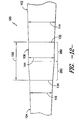
- the blade insert 106 may be configured to transition from a constant cross-section to a varying cross-section between the first and second interfaces 132, 134. Specifically, as shown in FIG.
- the blade insert 106 may transition along its length 150 from a constant portion 280, wherein the blade insert 106 defines a constant chord 144 and/or a constant aerodynamic shape/profile, to a varying portion 282, wherein the blade insert 106 defines a varying chord 144 and/or a varying aerodynamic shape/profile.
- the constant portion 280 extends from the first interface 132 and the varying portion 282 extends from the second interface 134.
- the blade insert 106 may be configured such that the varying portion 282 extends from the first interface 132 and the constant portion 280 extends from the second interface 134.
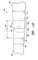
- the blade insert 106 may be configured to transition from a constant cross-section to a varying cross-section at more than one location along its length 150. For instance, as shown in FIG. 13 , in one embodiment, the blade insert 106 may transition from a constant portion 280 extending from the first interface 132 to a varying portion 282 and then back to a constant portion 280. Alternatively, as shown in FIG. 14 , the blade insert 106 may transition from a varying portion 282 extending from the first interface 132 to a constant portion 280 and then back to a varying portion 280. It should be appreciated that, in further embodiments, the blade insert 106 may be configured to transition from a constant cross-section to a varying cross-section at three or more locations along its length 150.
Landscapes
- Engineering & Computer Science (AREA)
- Life Sciences & Earth Sciences (AREA)
- Sustainable Development (AREA)
- Sustainable Energy (AREA)
- Chemical & Material Sciences (AREA)
- Combustion & Propulsion (AREA)
- Mechanical Engineering (AREA)
- General Engineering & Computer Science (AREA)
- Physics & Mathematics (AREA)
- Fluid Mechanics (AREA)
- Wind Motors (AREA)
- Turbine Rotor Nozzle Sealing (AREA)
Abstract
Description
- The present subject matter relates generally to wind turbines and, more particularly, to a blade insert for extending the length of a wind turbine rotor blade.
- Wind power is considered one of the cleanest, most environmentally friendly energy sources presently available, and wind turbines have gained increased attention in this regard. A modem wind turbine typically includes a tower, generator, gearbox, nacelle, and one or more turbine blades. The turbine blades capture kinetic energy from wind using known foil principles and transmit the kinetic energy through rotational energy to turn a shaft coupling the rotor blades to a gearbox, or if a gearbox is not used, directly to the generator. The generator then converts the mechanical energy to electrical energy that may be deployed to a utility grid.
- To ensure that wind power remains a viable energy source, efforts have been made to increase energy outputs by modifying the size and capacity of wind turbines. One such modification has been to increase the length of the rotor blades. However, as is generally known, the deflection of a rotor blade is a function of blade length, along with wind speed, turbine operating states and blade stiffness. Thus, longer rotor blades may be subject to increased deflection forces, particularly when a wind turbine is operating in high-speed wind conditions. These increased deflection forces not only produce fatigue on the rotor blades and other wind turbine components but may also increase the risk of the rotor blades striking the tower.
- In order to increase the length of wind turbine rotor blades without adversely affecting the aerodynamic design, it is known to install tip extensions onto the blades. Typically, a conventional tip extension is installed onto a rotor blade by cutting-off a portion of the blade at its tip and replacing such cut-off portion with the tip extension. However, due to the fact that a portion of the rotor blade must be cut-off and because the elongated rotor blade will be subjected to increased loads, the tip extension must be significantly longer than the actual increase in rotor blade length that can be achieved by installing the extension. For example, a conventional tip extension may often need to have a length of almost half of the original span of the rotor blade to accommodate the increased loading on the blade. As such, due to their length, the costs of manufacturing and transporting conventional tip extensions can be prohibitively expensive.
- Accordingly, a blade insert that can be used to increase the span of a rotor blade by an amount generally corresponding to the overall length of the blade insert would be welcomed in the technology.
- Various aspects and advantages of the invention will be set forth in part in the following description, or may be clear from the description, or may be learned through practice of the invention.
- In one aspect, the present subject is directed to a rotor blade assembly including a first blade segment having a first joint end and a second blade segment having a second joint end. In addition, the rotor blade assembly may include a blade insert having a first end coupled to the first joint end such that a first interface is defined between the blade insert and the first blade segment and a second end coupled to the second joint end such that a second interface is defined between the blade insert and the second blade segment. The blade insert may define a chord, wherein the chord at the first interface may be substantially equal to the chord at the second interface.
- In another aspect, the present subject matter is directed to a blade insert for coupling a first blade segment to a second blade segment. The blade insert may include an aerodynamic body extending between a first end configured to be coupled to the first blade segment and a second end configured to be coupled to the second blade segment. The aerodynamic body may include a pressure side and a suction side extending between a leading edge and a trailing edge. In addition, the aerodynamic body may define a chord, wherein the chord at the first end is substantially equal to the chord at the second end.
- In a further aspect, the present subject is directed to a rotor blade assembly including a first blade segment having a first joint end and a second blade segment having a second joint end. In addition, the rotor blade assembly may include a blade insert having a first end coupled to the first joint end such that a first interface is defined between the blade insert and the first blade segment and a second end coupled to the second joint end such that a second interface is defined between the blade insert and the second blade segment. The stiffness of the blade insert may be greater than a stiffness of at least one of the first blade segment at the first joint end or the second blade segment at the second joint end.
- Various features, aspects and advantages of the present invention will become better understood with reference to the following description and appended claims. The accompanying drawings, which are incorporated in and constitute a part of this specification, illustrate embodiments of the invention and, together with the description, serve to explain the principles of the invention. In the drawings:
-
FIG. 1 illustrates a perspective view of one embodiment of a wind turbine; -
FIG. 2 illustrates a perspective view of one embodiment of a rotor blade of a wind turbine; -
FIG. 3 illustrates a perspective, exploded view of one embodiment of a rotor blade assembly in accordance with aspects of the present subject matter; -
FIG. 4 illustrates a partial, side assembled view of the rotor blade assembly shown inFIG. 3 ; -
FIG. 5 illustrates a cross-sectional view of the rotor blade assembly shown inFIG. 4 taken about line 5-5; -
FIG. 6 illustrates an edge view of the rotor blade assembly shown inFIG. 4 viewing the rotor blade assembly from line 6-6; -
FIG. 7 illustrates a perspective view of one embodiment of attachment features that may be utilized to couple the components of the rotor blade assembly to one another; -
FIG. 8 illustrates an assembled, cross-sectional view of the components shown inFIG. 7 ; -
FIG. 9 illustrates an assembled, cross-sectional view of different attachment features that may be utilized to couple the components of the rotor blade assembly to one another; -
FIG. 10 illustrates a perspective, exploded view of another embodiment of a rotor blade assembly in accordance with aspects of the present subject matter; -
FIG. 11 illustrates a partial, side assembled view of the rotor blade assembly shown inFIG. 10 ; -
FIG. 12 illustrates a partial, side assembly view of another embodiment of a rotor blade assembly in accordance with aspects of the present subject matter; -
FIG. 13 illustrates a partial, side assembly view of a further embodiment of a rotor blade assembly in accordance with aspects of the present subject matter; -
FIG. 14 illustrates a partial, side assembly view of yet another embodiment of a rotor blade assembly in accordance with aspects of the present subject matter; and -
FIG. 15 illustrates a partial, side assembled view of one embodiment of a rotor blade assembly in which the blade insert is swept. - Reference now will be made in detail to embodiments of the invention, one or more examples of which are illustrated in the drawings. Each example is provided by way of explanation of the invention, not limitation of the invention. In fact, it will be apparent to those skilled in the art that various modifications and variations can be made in the present invention without departing from the scope or spirit of the invention. For instance, features illustrated or described as part of one embodiment can be used with another embodiment to yield a still further embodiment. Thus, it is intended that the present invention covers such modifications and variations as come within the scope of the appended claims and their equivalents.
- In general, the present subject matter is directed to a blade insert for extending the length of a wind turbine rotor blade. For example, in several embodiments, a pre-existing rotor blade may be divided into two blade segments, such as by cutting the pre-existing rotor blade at a specified location along its span. A blade insert may then be coupled between the blade segments in order to increase the overall length of the pre-existing rotor blade.
- Referring now to the drawings,
FIG. 1 illustrates perspective view of one embodiment of awind turbine 10. Thewind turbine 10 includes atower 12 with anacelle 14 mounted thereon. A plurality ofrotor blades 16 are mounted to arotor hub 18, which is, in turn, connected to a main flange that turns a main rotor shaft. The wind turbine power generation and control components (e.g., a turbine controller) may be housed within thenacelle 14. It should be appreciated that the view ofFIG. 1 is provided for illustrative purposes only to place the present subject matter in an exemplary field of use. Thus, one of ordinary skill in the art should readily appreciate that the present subject matter need not be limited to any particular type of wind turbine configuration. - Referring now to
FIG. 2 , a perspective view of one embodiment of one of therotor blades 16 shown inFIG. 1 is illustrated. As shown, therotor blade 16 generally includes ablade root 20 configured for mounting therotor blade 16 to thehub 18 of the wind turbine 10 (FIG. 1 ) and ablade tip 22 disposed opposite theblade root 20. Abody 24 of therotor blade 16 may generally be configured to extend between theblade root 20 and theblade tip 22 and may serve as the outer casing/skin of theblade 16. In several embodiments, thebody 24 may define a substantially aerodynamic profile, such as by defining a symmetrical or cambered airfoil-shaped cross-section. As such, thebody 24 may include apressure side 26 and asuction side 28 extending between a leadingedge 30 and atrailing edge 32. Further, therotor blade 16 may have aspan 34 defining the total length between theblade root 20 and theblade tip 22 and achord 36 defining the total length between the leadingedge 30 and thetrialing edge 32. As is generally understood, thechord 36 may vary in length with respect to thespan 34 as therotor blade 16 extends from theblade root 20 to theblade tip 22. - In several embodiments, the
body 24 of therotor blade 16 may be formed as a single, unitary component. Alternatively, thebody 24 may be formed from a plurality of shell components. For example, thebody 24 may be manufactured from a first shell half generally defining thepressure side 26 of therotor blade 16 and a second shell half generally defining thesuction side 28 of therotor blade 16, with the shell halves being secured to one another at the leading and trailingedges blade 16. Additionally, thebody 24 may generally be formed from any suitable material. For instance, in one embodiment, thebody 24 may be formed entirely from a laminate composite material, such as a carbon fiber reinforced laminate composite or a glass fiber reinforced laminate composite. Alternatively, one or more portions of thebody 24 may be configured as a layered construction and may include a core material, formed from a lightweight material such as wood (e.g., balsa), foam (e.g., extruded polystyrene foam) or a combination of such materials, disposed between layers of laminate composite material. - It should be appreciated that the
rotor blade 16 may also include one or more longitudinally extending structural components configured to provide increased stiffness, buckling resistance and/or strength to therotor blade 16. For example, in several embodiments, therotor blade 16 may include one or more shear webs 38 (FIG. 7 ) extending between corresponding spar caps 40 (FIG. 7 ). However, in other embodiments, therotor blade 16 of the present disclosure may have any other suitable internal configuration. - Referring now to
FIGS. 3-6 , one embodiment of arotor blade assembly 100 is illustrated in accordance with aspects of the present subject matter. Specifically,FIG. 3 illustrates a perspective, exploded view of therotor blade assembly 100.FIG. 4 illustrates a partial, pressure side view of therotor blade assembly 100.FIG. 5 illustrates a cross-sectional view of therotor blade assembly 100 shown inFIG. 4 taken about line 5-5. Additionally,FIG. 6 illustrates a leading edge view of therotor blade assembly 100 shown inFIG. 4 . - As shown, the
rotor blade assembly 100 may include afirst blade segment 102, asecond blade segment 104 and ablade insert 106 configured to be coupled between the first andsecond blade segments rotor blade assembly 100 may be configured such that, when the first andsecond blade segments blade insert 106, a complete rotor blade is formed. - In several embodiments, the first and
second blade segments pre-existing rotor blade 16 into two separate blade sections. For example, as shown inFIG. 2 , in one embodiment, the illustratedrotor blade 16 may be divided into the first andsecond blade segments rotor blade 16 along a joint or cutline 108. Thus, thefirst blade segment 102 may generally comprise a root segment of therotor blade 16 and may extend between theblade root 20 and a firstjoint end 110 formed at thecut line 108. Similarly, thesecond blade segment 104 may comprise a tip segment of therotor blade 16 and may extend between theblade tip 22 and a secondjoint end 112 formed at thecut line 108. In such an embodiment, eachblade segment chord edges FIGS. 3 and4 , thefirst blade segment 102 may define afirst chord 114 and thesecond blade segment 104 may define asecond chord 116, with thefirst chord 114 at the firstjoint end 110 being the same as or substantially the same as thesecond chord 116 at the secondjoint end 112. - By dividing a
pre-existing rotor blade 16 as described above, the total length of the first andsecond blade segments original span 34 of therotor blade 16. Specifically, thefirst blade segment 102 may define a firstspanwise length 118 and thesecond blade segment 104 may define a secondspanwise length 120 such that, when combined, the first and secondspanwise lengths original span 34. As used herein, the term "total segment length" will be used to refer to the combined length of the first and secondspanwise lengths - It should be appreciated that the first and second
spanwise lengths cut line 108. Thus, in several embodiments, the location of thecut line 108 may be selected in order to providespanwise lengths second blade segments blade insert 106 to be positioned along the length of therotor blade assembly 100 at a location that enhances the overall performance of theassembly 100 while minimizing performance impacts (e.g., deflection, moment of inertia, etc.). For example, in one embodiment, the location of thecut line 108 along therotor blade 16 may be selected such that the firstspanwise length 118 ranges from about 40% to about 95% of the total segment length, such as from about 40% to about 80% of the total segment length or from about 50% to about 65% of the total segment length. However, it is foreseeable that, in other embodiments, the location of thecut line 108 may be selected such that the firstspanwise length 118 is less then 40% of the total segment length or greater than 95% of the total segment length. - In other embodiments, the location of the
cut line 108 may be selected such that therotor blade 16 is divided outboard of its maximum chord location. For example, as shown inFIGS. 2 and3 , therotor blade 16 may be divided such that themaximum chord location 122 is included within thefirst blade segment 102. In a further embodiment, the location of thecut line 108 may be selected such that, when theblade insert 106 is coupled between the first andsecond blade segments gravity 124 of therotor blade assembly 100 is defined within thefirst blade segment 102. - It should be appreciated that, in alternative embodiments, the first and
second blade segments pre-existing rotor blade 16 into two separate blade sections. For example, in another embodiment, the first andsecond blade segments blade insert 106 to form the disclosedrotor blade assembly 100. - Additionally, it should be appreciated that, as used herein, the terms "first blade segment" and "second blade segment" need not be limited to a single, continuous blade segment. For example, the
first blade segment 102 may be formed from a single, unitary blade segment extending between theblade root 20 and the firstjoint end 110 or thefirst blade segment 102 may be formed from two or more blade segments that, when coupled together, extend betweenblade root 20 and the firstjoint end 110. Similarly, thesecond blade segment 104 may be formed from a single, unitary blade segment extending between the secondjoint end 112 and theblade tip 22 or thesecond blade segment 104 may be formed from two or more blade segments that, when coupled together, extend between the secondjoint end 112 and theblade tip 22. Moreover, it should be appreciated that, in alternative embodiments, therotor blade assembly 100 may be divided into three or more blade segment, with ablade insert 106 being coupled between each pair of adjacent blade segments. - Referring still to
FIGS. 3-6 , theblade insert 106 of therotor blade assembly 100 may generally comprise anelongated body 126 extending between afirst end 128 and asecond end 130. In general, theblade insert 106 may be configured to be coupled between the first andsecond blade segments rotor blade assembly 100. Specifically, as shown inFIG. 4 , thefirst end 128 of thebody 126 may be configured to be coupled to thejoint end 110 of thefirst blade segment 102 such that afirst interface 132 is defined between theblade insert 106 and thefirst blade segment 102. Similarly, thesecond end 130 of thebody 126 may be configured to be coupled to thejoint end 112 of thesecond blade segment 104 such that asecond interface 134 is defined between theblade insert 106 and thesecond blade segment 104. - The
body 126 of theblade insert 106 may also be configured to define a substantially aerodynamic profile, such as by defining a symmetric or cambered airfoil-shaped cross-section. Thus, as particularly shown inFIG. 5 , in several embodiments, thebody 126 may include apressure side 136 and asuction side 138 extending between aleading edge 140 and a trailingedge 142. In addition, thebody 126 may also define achord 144 corresponding to the overall length of theblade insert 106 between its leading and trailingedges - Moreover, in several embodiments, the
blade insert 106 may also include the same or similar internal structural components as the first andsecond blade segments FIG. 5 , theblade insert 106 may include a pair of longitudinally extending spar caps 146 configured to be aligned with the longitudinally extending spar caps 40 (FIG. 7 ) of theblade segments blade insert 106 may also include one or moreshear webs 148 extending between the spar caps 146 that generally correspond to the shear web(s) 38 of theblade segments blade insert 106 may include internal structural components that differ from the internal structural components of theblade segments - Referring still to
FIGS. 3-6 , in several embodiments, the cross-section of theblade insert 106 at its first and second ends 128, 130 may generally be configured to correspond to or otherwise match the cross-sections of the first andsecond blade segments blade segments pre-existing rotor blade 16 at thecut line 108, the cross-section of theinsert body 126 at thefirst interface 132 may be the same as or substantially the same as the cross-section of thebody 126 at thesecond interface 134. For example, in several embodiments, thechord 144 of theblade insert 106 at thefirst interface 132 may be the same as or substantially the same as thechord 144 at thesecond interface 134. Similarly, the aerodynamic profile/shape of theblade insert 106 at thefirst interface 132 may be the same as or substantially the same as the aerodynamic profile/shape of theblade insert 106 at thesecond interface 134. As such, when theblade insert 106 is coupled between the first andsecond blade segments second interfaces - Additionally, in several embodiments, the
blade insert 106 may be configured to define a constant or varied cross-section between the first andsecond interfaces blade insert 106 may be configured such that thebody 126 defines a constant or substantially constant cross-section between the first andsecond interfaces 132, 134 (e.g., by defining both a substantiallyconstant chord 144 and aerodynamic profile/shape between the first andsecond interfaces 132, 134). However, in other embodiments, thechord 144 and/or aerodynamic profile/shape of theblade insert 106 may be varied between the first andsecond interfaces blade insert 106 to define an aerodynamic profile/shape between the first andsecond interfaces second blade segment - Moreover, the
blade insert 106 may also define abody thickness 149. For example, as shown inFIGS. 5 ,8 and9 , abody thickness 149 may be defined between the inner and outer surfaces of thebody 126 of theblade insert 106. Similarly, the first andsecond blade segments body thickness 151. For instance, as shown inFIGS. 7-9 , thefirst blade segment 102 may define abody thickness 151 between its inner and outer surfaces. In several embodiments, thebody thickness 149 of theblade insert 106 may be the same as or substantially the same as thebody thickness 151 of the first and/or second blade segments at their joint ends 110, 112. Thus, in embodiments in which theblade insert 106 comprises a pre-fabricated component, the location of thecut line 108 may be selected so as to correspond to the location along thespan 34 of theblade 16 at which itsbody thickness 151 is equal or substantially equal to thebody thickness 149 of theblade insert 106. However, it should be appreciated that, in alternative embodiments, thebody thickness 149 of theblade insert 106 may differ from thebody thickness 151 of the first and/orsecond blade segments body thickness 149 of theblade insert 106 to be greater than thebody thickness 151 of both the first andsecond blade segments body thickness 149 of theblade insert 106 may be less than thebody thickness 151 of both the first andsecond blade segments - The
body 126 of theblade insert 106 may also define aspanwise length 150 along alongitudinal axis 152 extending between its first and second ends 128, 130. In general, thespanwise length 150 of thebody 126 may be selected to provide therotor blade assembly 100 increased efficiency (i.e., due to the overall increase in span) while taking into consideration relevant performance factors and/or operating conditions, such as the potential increases in deflection, thrust and/or torque that may result from the increased span. Thus, in several embodiments, thespanwise length 150 of theblade insert 106 may range from about 1 meter (m) to about 20 meters, such as from about 3 m to about 12 m or from about 5 m to about 8 m and all other subranges therbetween. However, it is foreseeable that theblade insert 106 may be configured such that itslength 150 is less than 1 m or greater than 20 meters. Additionally, in several embodiments, at least a portion of theblade insert 106 may be twisted about its longitudinal axis 152 (FIGS. 4 and6 ). For example, as shown inFIG. 5 , in one embodiment, thebody 126 of theblade insert 106 may be twisted about its longitudinal axis 152 (e.g., in the direction of arrow 154) such that the orientation of thechord 144 at thefirst interface 132 differs from the orientation of thechord 144 at thesecond interface 134 by atwist angle 156. Such twisting may allow for the angle of attack of therotor blade assembly 100 to be optimized, thereby increased its overall performance. - Moreover, in several embodiments, at least a portion of the
blade insert 106 may be curved relative to itslongitudinal axis 152. For example, as shown inFIG. 6 , thebody 126 of theblade insert 106 may be curved relative to itslongitudinal axis 152 such that theblade insert 106 defines an amount ofpre-bend 158 between the first andsecond interfaces rotor blade assembly 100 away from thetower 12 of a wind turbine 10 (FIG. 1 ), thereby increasing the tower clearance and decreasing the likelihood of a tower strike. - In addition, or as an alternative, to being pre-bent, the
blade insert 106 may also be curved or swept in the chordwise direction (i.e., the direction extending between the leading and trailingedges FIG. 15 , theblade insert 106 may be swept such that asweep angle 190 is defined between thelongitudinal axis 152 of theblade insert 106 and the longitudinal axis of thefirst blade segment 102. Such sweeping of theblade insert 106 may be utilized to lower the pitching or torque load on the pitch system of therotor blade assembly 100 or to help reduce overall loading on the wind turbine. - Further, in addition to defining an aerodynamic profile/shape, the
blade insert 106 may also be configured to include various other aerodynamic features (not shown). For instance, in several embodiments, theblade insert 106 may include one or more spoilers, vortex generators and/or other aerodynamic surface features. In another embodiment, theblade insert 106 may include one or more auxiliary airfoils mounted to thebody 126. - It should be appreciated that the
blade insert 106 may generally be formed from any suitable material(s), such as by being formed from the same material(s) used to form the first andsecond blade segments blade insert 106 from a material(s) having a greater stiffness (e.g., a greater flexural rigidity) than the material(s) used to form the first andsecond blade segments blade insert 106 may be formed from a material(s) having a greater stiffness than the material(s) used to form the first andsecond blade segments blade segments blade insert 106 may be configured to be greater than the stiffness of thefirst blade segment 102 at itsjoint end 110 and/or the stiffness of thesecond blade segment 104 at itsjoint end 112. Such increased stiffness may generally increase the rigidity of therotor blade assembly 100 and may also decrease the tip deflection of theassembly 100. - Additionally, in several embodiments, the material(s) and/or configuration of the
blade insert 106 may be designed such that theinsert 106 has a constant or substantially constant stiffness or flexural rigidity (EI) along itslength 150. Moreover, in one embodiment, theblade insert 106 may be designed such that its flexural rigidity is substantially equal to the flexural rigidity of thefirst blade segment 102 at itsjoint end 110 and/or thesecond blade segment 104 at itsjoint end 112. - Moreover, it should be appreciated that the
blade insert 106 may generally be configured to be coupled to first andsecond blade segments FIGS. 7 and8 illustrate one embodiment of an attachment means/method that may be utilized to attach theblade insert 106 to the joint ends 110, 112 of the first andsecond blade segments FIG. 7 illustrates a partial, perspective view of thejoint end 110 of thefirst blade segment 102 and thefirst end 128 of theblade insert 106. Additionally,FIG. 8 illustrates a cross-sectional view of theblade segment 102 andblade insert 106 shown inFIG. 7 after such components have been assembled together. It should be appreciated that, althoughFIGS. 7 and8 will be described below with reference to forming a joint at thefirst interface 132 defined between thefirst blade segment 102 and theblade insert 106, the same or similar features, components and/or configuration may also be utilized to form a joint at thesecond interface 134 defined between thesecond blade segment 104 and theblade insert 106. - As shown, in several embodiments, the
blade insert 106 may be coupled to thefirst blade segment 102 by forming a scarf joint at thefirst interface 132. Specifically, one or more tapered or scarfedsections first blade segment 102 at itsjoint end 110 and along the outer perimeter of theblade insert 106 at itsfirst end 128. For example, as particularly shown inFIG. 7 , scarfedsections joint end 110 along the pressure and/orsuction sides first blade segment 102, such as by forming a scarfedsection 160 at a spar cap location on the pressure and/orsuction sides spar cap 40 of the blade segment 102) and/or by forming a scarfedsection 162 at a trailing edge location on the pressure and/orsuction sides edge 32 of the blade segment 102). In such an embodiment, corresponding scarfedsections first end 128 of theblade insert 106, such as by forming a scarfedsection 164 at a spar cap location on the pressure and/orsuction sides first end 128 that corresponds to the scarfed section(s) 160 formed in theblade segment 102 and/or by forming a scarfedsection 166 at a trailing edge location on the pressure and/orsuction sides first end 128 that corresponds to the scarfed section(s) 162 formed in theblade segment 102. As such, the scarfed section(s) 160, 162 formed at thejoint end 110 of theblade segment 102 may be aligned with the scarfed section(s) 164, 166 formed at theend 128 of theblade insert 106 when theblade segment 102 andblade insert 106 are assembled together. - It should be appreciated that, that although the illustrated embodiment show the
blade segment 102 and theblade insert 106 as each including a pair of scarfedsections blade segment 110 andblade insert 106 may generally include any number of scarfed sections formed at any suitable location along the outer circumference of theends blade segment 102 and theblade insert 106 may be scarfed around the entire outer circumference of theirends - It should also be appreciated that the scarfed
sections blade segment 102 and theblade insert 106 such that each scarfedsection transition point 168 to theend blade segment 102 orblade insert 106. - As particularly shown in
FIG. 8 , when theblade segment 102 andblade insert 106 are positioned together such that the corresponding scarfedsections tapered coupling 170 may be secured across each pair of aligned scarfedsections blade insert 106 to theblade segment 102. Specifically, as shown, eachtapered coupling 170 may be configured to extend across theinterface 132 defined between theblade segment 102 and theblade insert 106 so as to fill the area defined by the aligned scarfedsections - In several embodiments, each
tapered coupling 170 may comprise a pre-fabricated component configured to be separately secured within each pair of aligned scarfedsections tapered coupling 170 within each pair of aligned scarfedsections tapered coupling 170 may be formed or otherwise built-up within each pair of aligned scarfedsections tapered coupling 170 may be formed using a wet lay-up process, wherein a plurality of plies (including a reinforcement material such as glass or carbon fibers) are positioned across and/or within the aligned scarfedsections - Additionally, in several embodiments, the
rotor blade assembly 100 may also include various other structural components to enhance the strength of the joints formed between theblade segments blade insert 106. For example, as shown inFIG. 7 , in one embodiment, aleading edge insert 172 may be installed across thefirst interface 132 and/or thesecond interface 134 at theleading edges blade insert 106. Specifically, as shown, the leadingedge insert 172 may define a curved profile generally corresponding to the curved profiles of theleading edges blade insert 106. As such, the leadingedge insert 172 may be secured across thefirst interface 132 and/or thesecond interface 134 by coupling theinsert 172 to the inner surfaces of theblade segments blade insert 106 using suitable adhesives and/or mechanical fasteners. - Moreover, in several embodiments, the
rotor blade assembly 100 may also include one or moreshear web couplings 174 configured to be secured to theshear webs blade segments blade insert 106. For example, as shown inFIGS. 7 and8 , first and secondshear web couplings 174 may be secured to each side of theshear webs 38, 148 (e.g., using a suitable adhesive and/or mechanical fasteners) so as to extend across the first and/orsecond interface - As an alternative to forming the scarf joint described above, it should be appreciated that any other suitable joint configuration may be used to couple the
blade insert 106 to the first andsecond blade segments FIG. 9 illustrates a cross-sectional view of one embodiment of a doubler joint that may be formed at theinterfaces blade insert 106 and the first andsecond blade segments FIG. 9 will be described below with reference to forming a joint at thefirst interface 132 defined between thefirst blade segment 102 and theblade insert 106, the same or similar features, components and/or configuration may also be utilized to form a joint at thesecond interface 134 defined between thesecond blade segment 104 and theblade insert 106. - As shown in
FIG. 9 , in several embodiments, one or moreouter doublers 176 may be secured to an outer surface 178 of theblade segment 102 and an outer surface 180 of theblade insert 106 so as to extend across thefirst interface 132, such as by securing one or moreouter doublers 176 across theinterface 132 on the suction sides 28, 138 of theblade segment 102 and theblade insert 106 and/or by securing one or moreouter doublers 176 across theinterface 132 on the pressure sides 26, 138 of theblade segment 102 and theblade insert 106. In such embodiments, it should be appreciated that theouter doublers 176 may generally be positioned at any suitable location around the outer circumference of theinterface 132. However, in a particular embodiment, theouter doublers 176 may be secured across theinterface 132 at a spar cap location of theblade segment 102 and theblade insert 106 such that theouter doublers 176 are longitudinally aligned with the spar caps 40, 146. - Additionally, as shown in
FIG. 9 , one or moreinner doublers 182 may be secured to aninner surface 184 of theblade segment 102 and aninner surface 186 of theblade insert 106 so as to extend across thefirst interface 132, such as by securing one or moreinner doublers 182 across theinterface 132 on the suction sides 28, 138 of theblade segment 102 and theblade insert 106 and/or by securing one or moreinner doublers 182 across theinterface 132 on the pressure sides 26, 136 of theblade segment 102 and the blade insert 105. Similar to theouter doublers 176, theinner doublers 182 may generally be positioned at any suitable location around the inner circumference of theinterface 132. For example, in a particular embodiment, a pair of inner doublers 182 (one of which is shown) may be secured across theinterface 132 so as to extend longitudinally adjacent to the sides of theshear webs suction sides blade segment 102 and theblade insert 106. - It should be appreciated that the
doublers doublers FIG. 9 , eachdoubler doublers interface 132. However, in other embodiments, thedoublers - It should also be appreciated that, in several embodiments, the
doublers outer surfaces blade segments blade insert 106. Alternatively, thedoublers doubler outer surfaces - Additionally, it should be appreciated that the illustrated doubler joint may also be utilized with one or more of the components and/or features described above with reference to
FIGS. 7 and8 . For example, in one embodiment, a doubler joint may be formed across a spar cap location on theblade segments blade insert 106 and a scarf joint may be formed across a trailing edge location on theblade segments blade insert 106. Additionally, in another embodiment, aleading edge insert 172 and/orshear web couplings 174 may be utilized together with the above-described doubler joint. - Moreover, one of ordinary skill in the art should readily appreciate that the
blade segments blade insert 106 may be coupled together using any other suitable joint technology and/or attachment means/method known in the art and, thus, the present subject matter need not be limited to the specific examples described above with reference toFIGS. 7-9 . For example, in another embodiment, theends blade insert 106 may be tapered or recessed so that such ends 128, 130 may be received within theblade segments interface blade insert 106 to each of theblade segments - It should also be appreciated that the present subject matter is also directed to a method for extending the length of a
rotor blade 16. In several embodiments, the method may include dividing arotor blade 16 at a specified location (e.g., at cut line 108) into afirst blade segment 102 and asecond blade segment 104, coupling afirst end 128 of ablade insert 106 to ajoint end 110 of thefirst blade segment 102 such that afirst interface 132 is defined between theblade insert 106 and thefirst blade segment 102 and coupling asecond end 130 of theblade insert 106 to ajoint end 112 of thesecond blade segment 104 such that asecond interface 134 is defined between theblade insert 106 and thesecond blade segment 104. Additionally, the present subject matter also discloses a method for retrofitting arotor blade 16 of awind turbine 10. In several embodiments, the method may include cutting therotor blade 16 at a specified location (e.g., at cut line 108) in order to form aroot segment 102 and atip segment 106 and positioning ablade insert 106 between theroot segment 102 and thetip segment 104. In other embodiments, the method for retrofitting therotor blade 16 may include removing asection 188 of therotor blade 16 between ablade root 20 and ablade tip 22 of therotor blade 16 and positioning ablade insert 106 at the location of the removedsection 188 of therotor blade 16. - As indicated above, in several embodiments, a
pre-existing rotor blade 16 may be divided into the first andsecond blade segments rotor blade 16 into two separate blade sections (e.g., at the cut line 108). In such embodiments, therotor blade 16 may generally be cut into the two separate blade sections using any suitable cutting means and/or process known in the art. For example, in one embodiment, therotor blade 16 may be cut using any suitable hand-held cutting equipment (e.g., by using any suitable manual cutting devices, such as saws, knives, etc., and/or automatic cutting devices, such as electric or gas-powered saws, grinders, etc.) and/or using any suitable cutting machinery (e.g., an EDM machine, water jet cutting machine, etc.). - Moreover, in several embodiments, a section of a
pre-existing rotor blade 16 may be removed prior to installing theblade insert 102. For example, in addition to cutting therotor blade 16 in order to form the first andsecond blade segments blade segments blade insert 106 to theblade segments second blade segment FIG. 10 , in one embodiment, therotor blade 16 may be initially cut along thecut line 108 in order to divide theblade 16 into the first andsecond blade segments section 188 of the second blade segment 104 (or, in an alternative embodiment, a section of the first blade segment 102) may be removed at its joint end 112 (e.g., by cutting thesecond blade segment 104 along line 192) such that thesecond blade segment 104 defines a newjoint end 192 having achord 116 that differs from thechord 114 defined at thejoint end 110 of thefirst blade segment 102. In such an embodiment, it should be appreciated that, in contrast to the embodiments described above, theblade insert 106 may define a varyingchord 144 along itslength 150. For example, as shown inFIG. 11 , theblade insert 106 may define achord 144 at thefirst interface 132 that is larger than thechord 144 defined at thesecond interface 134. In addition, other parameters of theblade insert 106 may also be varied along itslength 150, such as thebody thickness 149, the aerodynamic shape/profile and/or any other suitable parameter. - It should be appreciated that the disclosed methods may also include various other method elements, such as dividing the rotor blade 16 at a specified location between about 40% to about 95% of an original span 34 of the rotor blade 16, dividing the rotor blade 16 at a specified location outboard of a maximum chord location 122 for the rotor blade 16, dividing the rotor blade 16 at a specified location such that a center of gravity 124 of the rotor blade 16 is positioned within the first blade segment 102, forming a scarfed section 160, 162 in at least one of the first blade segment 102 or the second blade segment 104, forming a corresponding scarfed section 164, 166 in the blade insert 102, aligning the scarfed section 160, 162 of the at least one of the first blade segment 102 or the second blade segment 104 with the scarfed section 164, 166 of the blade insert 102, positioning a tapered coupling 170 across the aligned scarfed sections 160, 162, 164, 166, positioning a doubler 176, 182 across at least one of the first interface 132 or the second interface 134, positioning a leading edge insert 172 across at least one of the first interface 132 or the second interface 134 and/or coupling a shear web 148 of the blade insert 106 to a shear web 38 of the at least one the first blade segment 102 or the second blade segment 106.
- It should also be appreciated that the disclosed
rotor blade assembly 100 may also be modified to include a tip extension (e.g., a straight tip extension or a winglet) or a root extension in addition to theblade insert 106 coupled between the first and second blade segments. - Additionally, it should be appreciated that, as an alternative to configuring the
blade insert 106 such that it defines a constant cross-section along its length 150 (as shown inFIG. 4 ) or a continuously varying cross-section along its length 150 (as shown inFIG. 11 ), theblade insert 106 may also be configured to have both constant and varying cross-sections along itslength 150. For instance, in several embodiments, theblade insert 106 may be configured to transition from a constant cross-section to a varying cross-section between the first andsecond interfaces FIG. 12 , in one embodiment, theblade insert 106 may transition along itslength 150 from aconstant portion 280, wherein theblade insert 106 defines aconstant chord 144 and/or a constant aerodynamic shape/profile, to a varyingportion 282, wherein theblade insert 106 defines a varyingchord 144 and/or a varying aerodynamic shape/profile. As shown in the illustrated embodiment, theconstant portion 280 extends from thefirst interface 132 and the varyingportion 282 extends from thesecond interface 134. However, in an alternative embodiment, theblade insert 106 may be configured such that the varyingportion 282 extends from thefirst interface 132 and theconstant portion 280 extends from thesecond interface 134. - Moreover, in further embodiments, the
blade insert 106 may be configured to transition from a constant cross-section to a varying cross-section at more than one location along itslength 150. For instance, as shown inFIG. 13 , in one embodiment, theblade insert 106 may transition from aconstant portion 280 extending from thefirst interface 132 to a varyingportion 282 and then back to aconstant portion 280. Alternatively, as shown inFIG. 14 , theblade insert 106 may transition from a varyingportion 282 extending from thefirst interface 132 to aconstant portion 280 and then back to a varyingportion 280. It should be appreciated that, in further embodiments, theblade insert 106 may be configured to transition from a constant cross-section to a varying cross-section at three or more locations along itslength 150. - This written description uses examples to disclose the invention, including the preferred mode, and also to enable any person skilled in the art to practice the invention, including making and using any devices or systems and performing any incorporated methods. The patentable scope of the invention is defined by the claims, and may include other examples that occur to those skilled in the art. Such other examples are intended to be within the scope of the claims if they include structural elements that do not differ from the literal language of the claims, or if they include equivalent structural elements with insubstantial differences from the literal languages of the claims.
- Various aspects and embodiments of the present invention are defined by the following numbered clauses:
- 1. A rotor blade assembly, comprising:
- a first blade segment having a first joint end;
- a second blade segment having a second joint end; and,
- a blade insert having a first end coupled to the first joint end such that a first interface is defined between the blade insert and the first blade segment and a second end coupled to the second joint end such that a second interface is defined between the blade insert and the second blade segment, the blade insert defining a chord, the chord at the first interface being substantially equal to the chord at the second interface.
- 2. The rotor blade assembly of clause 1, wherein the chord of the blade insert is substantially constant between the first and second interfaces.
- 3. The rotor blade assembly of any preceding clause, wherein the blade insert defines an airfoil-shaped cross-section, the airfoil shaped cross-section at the first interface being substantially the same as the airfoil-shaped cross-section at the second interface.
- 4. The blade insert of any preceding clause, wherein the airfoil-shaped cross-section of the blade insert is substantially constant between the first and second interfaces.
- 5. The rotor blade assembly of any preceding clause, wherein the blade insert defines a length between the first and second ends ranging from about 1 meter to about 20 meters.
- 6. The rotor blade assembly of any preceding clause, wherein the first blade segment defines a first length and the second blade segment defines a second length, the first and second lengths together defining a total segment span, wherein the first length ranges from about 40% to about 95% of the total segment span.
- 7. The rotor blade assembly of any preceding clause, wherein the first blade segment defines a maximum chord location for the rotor blade assembly.
- 8. The rotor blade assembly of any preceding clause, wherein a center of gravity of the rotor blade assembly is positioned within the first blade segment.
- 9. The rotor blade assembly of any preceding clause, wherein the blade insert defines a longitudinal axis between the first and second ends, at least a portion of the blade insert being twisted about the longitudinal axis.
- 10. The rotor blade assembly of any preceding clause, wherein the blade insert defines a longitudinal axis between the first and second ends, at least a portion of the blade insert being curved relative to the longitudinal axis.
- 11. The rotor blade assembly of any preceding clause, wherein at least a portion of the blade insert is formed from a material having a greater stiffness than a material used to form the first and second blade segments.
- 12. The rotor blade assembly of any preceding clause, wherein the blade insert has a constant stiffness between the first and second interfaces.
- 13. The rotor blade assembly of any preceding clause, wherein the first blade segment comprises a root segment and the second blade segment comprises a tip segment.
- 14. A blade insert for coupling a first blade segment to a second blade segment, the blade insert comprising:
- an aerodynamic body extending between a first end configured to be coupled to the first blade segment and a second end configured to be coupled to the second blade segment, the aerodynamic body including a pressure side and a suction side extending between a leading edge and a trailing edge, the aerodynamic body defining a chord, the chord at the first end being substantially equal to the chord at the second end.
- 15. The blade insert of any preceding clause, wherein the chord is substantially constant between the first and second ends.
- 16. The blade insert of any preceding clause, wherein the aerodynamic body defines an airfoil-shaped cross-section, the airfoil shaped cross-section at the first end being substantially the same as to the airfoil-shaped cross-section at the second end.
- 17. The blade insert of any preceding clause, wherein the aerodynamic body defines a length between the first and second ends ranging from about 1 meter to about 20 meters.
- 18. The blade insert of any preceding clause, wherein the aerodynamic y defines a longitudinal axis between the first and second ends, at least a portion of the aerodynamic body being twisted about the longitudinal axis.
- 19. The blade insert of any preceding clause, wherein the aerodynamic body defines a longitudinal axis between the first and second ends, at least a portion of the aerodynamic body being curved relative to the longitudinal axis.
- 20. A rotor blade assembly, comprising:
- a first blade segment having a first joint end;
- a second blade segment having a second joint end; and,
- a blade insert having a first end coupled to the first joint end such that a first interface is defined between the blade insert and the first blade segment and a second end coupled to the second joint end such that a second interface is defined between the blade insert and the second blade segment,
- wherein a stiffness of the blade insert is greater than a stiffness of at least one of the first blade segment at the first joint end or the second blade segment at the second joint end.
- 21. A rotor blade assembly, comprising:
- a first blade segment having a first joint end;
- a second blade segment having a second joint end; and,
- a blade insert having a first end coupled to the first joint end such that a first interface is defined between the blade insert and the first blade segment and a second end coupled to the second joint end such that a second interface is defined between the blade insert and the second blade segment,
- wherein the blade insert transitions between a constant cross-section and a varying cross-section between the first and second interfaces.
- 22. The rotor blade assembly of any preceding clause, wherein the blade insert transitions between a constant cross-section and a varying cross-section at more than one location between the first and second interfaces.
Claims (15)
- A rotor blade assembly (16), comprising:a first blade segment (20) having a first joint end;a second blade segment (22) having a second joint end; anda blade insert (106) having a first end coupled to the first joint end such that a first interface is defined between the blade insert (106) and the first blade segment (20) and a second end coupled to the second joint end such that a second interface is defined between the blade insert and the second blade segment (22), the blade insert (106) defining a chord, the chord at the first interface being substantially equal to the chord at the second interface.
- The rotor blade assembly (16) of claim 1, wherein the chord of the blade insert (106) is substantially constant between the first and second interfaces.
- The rotor blade assembly (16) of any preceding claim, wherein the blade insert (106) defines an airfoil-shaped cross-section, the airfoil shaped cross-section at the first interface being substantially the same as the airfoil-shaped cross-section at the second interface.
- The rotor blade assembly (16) of claim 3, wherein the airfoil-shaped cross-section of the blade insert (106) is substantially constant between the first and second interfaces.
- The rotor blade assembly (16) of any preceding claim, wherein the blade insert (106) defines a length between the first and second ends ranging from about 1 meter to about 20 meters.
- The rotor blade assembly (16) of any preceding claim, wherein the first blade segment (20) defines a first length and the second blade segment (22) defines a second length, the first and second lengths together defining a total segment span, wherein the first length ranges from about 40% to about 95% of the total segment span.
- The rotor blade assembly (16) of any preceding claim, wherein the first blade segment (20) defines a maximum chord location for the rotor blade assembly.
- The rotor blade assembly (16) of any preceding claim, wherein a center of gravity of the rotor blade assembly (16) is positioned within the first blade segment (20).
- The rotor blade assembly (16) of any preceding claim, wherein the blade insert (106) defines a longitudinal axis between the first and second ends, at least a portion of the blade insert being twisted about the longitudinal axis.
- The rotor blade assembly (16) of any preceding claim, wherein the blade insert (106) defines a longitudinal axis between the first and second ends, at least a portion of the blade insert being curved relative to the longitudinal axis.
- The rotor blade assembly (16) of any preceding claim, wherein at least a portion of the blade insert (106) is formed from a material having a greater stiffness than a material used to form the first and second blade segments.
- The rotor blade assembly (16) of any preceding claim, wherein the blade insert (106) has a constant stiffness between the first and second interfaces.
- The rotor blade assembly (16) of any preceding claim, wherein the first blade segment (20) comprises a root segment and the second blade segment comprises a tip segment.
- A blade insert (106) for coupling a first blade segment (20) to a second blade segment (22), the blade insert (106) comprising:an aerodynamic body (126) extending between a first end configured to be coupled to the first blade segment and a second end configured to be coupled to the second blade segment, the aerodynamic body including a pressure side and a suction side extending between a leading edge and a trailing edge, the aerodynamic body defining a chord, the chord at the first end being substantially equal to the chord at the second end.
- The blade insert (106) of claim 14, wherein the chord is substantially constant between the first and second ends.
Applications Claiming Priority (1)
| Application Number | Priority Date | Filing Date | Title |
|---|---|---|---|
| IN573DE2012 IN2012DE00573A (en) | 2012-02-29 | 2012-02-29 |
Publications (3)
| Publication Number | Publication Date |
|---|---|
| EP2634417A2 true EP2634417A2 (en) | 2013-09-04 |
| EP2634417A3 EP2634417A3 (en) | 2016-12-14 |
| EP2634417B1 EP2634417B1 (en) | 2022-04-06 |
Family
ID=47722083
Family Applications (1)
| Application Number | Title | Priority Date | Filing Date |
|---|---|---|---|
| EP13154817.4A Active EP2634417B1 (en) | 2012-02-29 | 2013-02-11 | Blade insert for a wind turbine rotor blade |
Country Status (7)
| Country | Link |
|---|---|
| US (1) | US20130224032A1 (en) |
| EP (1) | EP2634417B1 (en) |
| CN (1) | CN103291537B (en) |
| CA (1) | CA2806793C (en) |
| DK (1) | DK2634417T3 (en) |
| ES (1) | ES2910416T3 (en) |
| IN (1) | IN2012DE00573A (en) |
Cited By (5)
| Publication number | Priority date | Publication date | Assignee | Title |
|---|---|---|---|---|
| WO2015189338A1 (en) * | 2014-06-11 | 2015-12-17 | Lm Wp Patent Holding A/S | A tip system for a wind turbine blade |
| WO2019023031A1 (en) * | 2017-07-27 | 2019-01-31 | General Electric Company | Injection method and device for connecting and repairing a shear web |
| WO2019162114A1 (en) * | 2018-02-20 | 2019-08-29 | Wobben Properties Gmbh | Rotor blade for a wind turbine and method |
| CN111094740A (en) * | 2017-08-17 | 2020-05-01 | 通用电气公司 | Scarf joint connection of misaligned spar caps |
| WO2023083892A1 (en) * | 2021-11-10 | 2023-05-19 | Lm Wind Power A/S | Method for manufacturing a sharp-edged composite part for a wind turbine blade |
Families Citing this family (33)
| Publication number | Priority date | Publication date | Assignee | Title |
|---|---|---|---|---|
| JP5996083B2 (en) * | 2013-02-18 | 2016-09-21 | 三菱重工業株式会社 | Wind turbine blade and manufacturing method thereof |
| US9506452B2 (en) * | 2013-08-28 | 2016-11-29 | General Electric Company | Method for installing a shear web insert within a segmented rotor blade assembly |
| WO2015067637A1 (en) * | 2013-11-06 | 2015-05-14 | Lm Wp Patent Holding A/S | A joining method for wind turbine blade shells |
| CN104747384A (en) * | 2013-12-30 | 2015-07-01 | 谢宛芝 | Special three-dimensional turbine blade for multipurpose integrated turbine generator |
| GB2539237B (en) * | 2015-06-10 | 2020-12-09 | Equinor Asa | Rotor blade shaped to enhance wake diffusion |
| US20160377050A1 (en) * | 2015-06-29 | 2016-12-29 | General Electric Company | Modular wind turbine rotor blades and methods of assembling same |
| US11125205B2 (en) * | 2015-09-14 | 2021-09-21 | General Electric Company | Systems and methods for joining blade components of rotor blades |
| US10570879B2 (en) * | 2017-05-23 | 2020-02-25 | General Electric Company | Joint assembly for a wind turbine rotor blade with flanged bushings |
| US10801469B2 (en) * | 2017-11-07 | 2020-10-13 | General Electric Company | Wind blade joints with floating connectors |
| DE102018103344A1 (en) * | 2018-02-14 | 2019-08-14 | Wobben Properties Gmbh | Method for producing a split rotor blade and rotor blade |
| DE102018112833A1 (en) * | 2018-05-29 | 2019-12-05 | Wobben Properties Gmbh | Wind turbine rotor blade |
| US10830207B2 (en) * | 2018-08-28 | 2020-11-10 | General Electric Company | Spar configuration for jointed wind turbine rotor blades |
| WO2020086080A1 (en) | 2018-10-25 | 2020-04-30 | General Electric Company | Spar cap configuration for a jointed wind turbine blade |
| US11162476B2 (en) * | 2018-10-30 | 2021-11-02 | General Electric Company | Wind turbine rotor blade pre-staged for retrofitting with a replacement blade tip segment |
| WO2020092458A1 (en) | 2018-10-31 | 2020-05-07 | General Electric Company | Jointed wind turbine rotor blade having varying material combinations along its span for pin reinforcement |
| CN112912614A (en) | 2018-11-01 | 2021-06-04 | 通用电气公司 | Method for mounting and retaining a bushing in a carrier block of a rotor blade joint |
| EP3874140A1 (en) | 2018-11-01 | 2021-09-08 | General Electric Company | Scarf connection for a wind turbine rotor blade |
| CN112912615A (en) | 2018-11-01 | 2021-06-04 | 通用电气公司 | Wind turbine engaged rotor blade with hollow chordwise extending pin |
| AU2018447565A1 (en) | 2018-11-01 | 2021-05-27 | General Electric Renovables España, S.L. | Compliant structures for jointed rotor blades |
| US11536246B2 (en) | 2018-11-01 | 2022-12-27 | General Electric Company | Span-wise extending pin for joining rotor blade segments |
| WO2020091791A1 (en) | 2018-11-01 | 2020-05-07 | General Electric Company | Spacer material for reducing a bond gap between a beam structure and a blade shell of a segmented rotor blade |
| AU2018452334A1 (en) | 2018-12-11 | 2021-07-08 | General Electric Renovables España, S.L. | Method for manufacturing a structural component of a blade segment for a rotor blade of a wind turbine |
| JP7234371B2 (en) | 2018-12-11 | 2023-03-07 | ゼネラル・エレクトリック・カンパニイ | Beam structure for segmented rotor blades with transition geometry |
| DK3894191T3 (en) | 2018-12-11 | 2023-10-02 | Gen Electric | METHOD OF MANUFACTURE OF WIND COMPONENTS FOR WIND TURBINE ROTOR BLADES |
| MX2021006433A (en) | 2018-12-11 | 2021-06-23 | Gen Electric | Method for manufacturing a structural component of a blade segment for a rotor blade of a wind turbine. |
| JP7282889B2 (en) | 2018-12-11 | 2023-05-29 | ゼネラル・エレクトリック・カンパニイ | Method for manufacturing hollow composite structures, particularly spar beams for wind turbine rotor blades, and associated mandrels |
| US11614069B2 (en) | 2018-12-13 | 2023-03-28 | General Electric Company | Jointed rotor blade having a chord-wise extending pin supported via one or more structural members |
| EP3894693B1 (en) * | 2018-12-14 | 2024-07-10 | Vestas Wind Systems A/S | Wind turbine blade |
| CN113167217B (en) | 2018-12-19 | 2024-06-07 | Lm风力发电公司 | Bonded rotor blade with internal support structure having different fiber orientations for pin reinforcement |
| JP7334251B2 (en) | 2018-12-20 | 2023-08-28 | ゼネラル・エレクトリック・カンパニイ | Rotor blade segments secured together via an internal support structure that defines a variable size gap |
| US11795907B2 (en) | 2018-12-20 | 2023-10-24 | General Electric Company | Jointed wind turbine rotor blade having spar cap constructed of varying forms of materials along its span |
| SE544491C2 (en) * | 2020-09-24 | 2022-06-21 | Modvion Ab | Rotor blade and method for assembly of a rotor blade |
| CN114183296B (en) * | 2021-11-10 | 2022-06-21 | 常州市宏发纵横新材料科技股份有限公司 | Wind-powered electricity generation blade spanwise piecemeal connection structure |
Family Cites Families (40)
| Publication number | Priority date | Publication date | Assignee | Title |
|---|---|---|---|---|
| FR1187166A (en) * | 1957-11-14 | 1959-09-08 | Improvements made to blade machines, particularly wind turbines | |
| US4474536A (en) * | 1980-04-09 | 1984-10-02 | Gougeon Brothers, Inc. | Wind turbine blade joint assembly and method of making wind turbine blades |
| FR2617118B1 (en) * | 1987-06-29 | 1992-08-21 | Aerospatiale | CURVED END BLADE FOR AIRCRAFT TURNING WING |
| US5137427A (en) * | 1990-12-20 | 1992-08-11 | United Technologies Corporation | Quiet tail rotor |
| US6638466B1 (en) * | 2000-12-28 | 2003-10-28 | Raytheon Aircraft Company | Methods of manufacturing separable structures |
| DK175562B1 (en) * | 2002-03-19 | 2004-12-06 | Lm Glasfiber As | Wind turbine blade with carbon fiber tip |
| DK175275B1 (en) * | 2002-03-19 | 2004-08-02 | Lm Glasfiber As | Transition area in wind turbine blade |
| DE10235496B4 (en) * | 2002-08-02 | 2015-07-30 | General Electric Co. | Method for producing a rotor blade, rotor blade and wind energy plant |
| PT1603735E (en) * | 2003-03-06 | 2007-06-15 | Vestas Wind Sys As | Connection between composites with non-compatible properties and method for preparation |
| CA2517966C (en) * | 2003-03-06 | 2008-03-25 | Vestas Wind Systems A/S | Connection between members |
| WO2006002621A1 (en) * | 2004-06-30 | 2006-01-12 | Vestas Wind Systems A/S | Wind turbine blades made of two separate sections, and method of assembly |
| US7246998B2 (en) * | 2004-11-18 | 2007-07-24 | Sikorsky Aircraft Corporation | Mission replaceable rotor blade tip section |
| DK176176B1 (en) * | 2004-11-24 | 2006-11-27 | Siemens Wind Power As | Method and connector for assembling a blade, preferably wind turbine blade, into sections |
| US7690895B2 (en) * | 2005-07-29 | 2010-04-06 | General Electric Company | Multi-piece passive load reducing blades and wind turbines using same |
| US7654799B2 (en) * | 2006-04-30 | 2010-02-02 | General Electric Company | Modular rotor blade for a wind turbine and method for assembling same |
| US20080232966A1 (en) * | 2007-03-20 | 2008-09-25 | Wen-Chang Wang | Detachable blade assembly for horizontal-axis wind turbine |
| ES2343712B1 (en) * | 2007-05-03 | 2011-05-18 | Manuel Torres Martinez | AEROGENERATOR SHOVEL DIVIDED IN SECTIONS AND MANUFACTURING PROCESS OF THE SAME. |
| US8221085B2 (en) * | 2007-12-13 | 2012-07-17 | General Electric Company | Wind blade joint bonding grid |
| US7740453B2 (en) * | 2007-12-19 | 2010-06-22 | General Electric Company | Multi-segment wind turbine blade and method for assembling the same |
| US8171633B2 (en) * | 2007-12-19 | 2012-05-08 | General Electric Company | Method for assembling a multi-segment wind turbine blade |
| US8167569B2 (en) * | 2007-12-21 | 2012-05-01 | General Electric Company | Structure and method for self-aligning rotor blade joints |
| US8231351B2 (en) * | 2007-12-27 | 2012-07-31 | General Electric Company | Adaptive rotor blade for a wind turbine |
| DK2288807T3 (en) * | 2008-05-07 | 2013-12-09 | Vestas Wind Sys As | SECTIONAL WINGS |
| EP2123556B1 (en) * | 2008-05-22 | 2010-12-08 | Agusta S.p.A. | Helicopter antitorque tail rotor blade |
| GB2462307A (en) * | 2008-08-01 | 2010-02-03 | Vestas Wind Sys As | Extension portion for wind turbine blade |
| FR2937689B1 (en) * | 2008-10-23 | 2010-12-17 | Astrium Sas | DEVICE AND METHOD FOR ASSEMBLING WINDMILL BLADES |
| US7891947B2 (en) * | 2008-12-12 | 2011-02-22 | General Electric Company | Turbine blade and method of fabricating the same |
| ES2542869T3 (en) * | 2009-01-27 | 2015-08-12 | Vestas Wind Systems A/S | Wind turbine blade divided into sections |
| US7988421B2 (en) * | 2009-03-31 | 2011-08-02 | General Electric Company | Retrofit sleeve for wind turbine blade |
| US7998303B2 (en) * | 2009-05-28 | 2011-08-16 | General Electric Company | Method for assembling jointed wind turbine blade |
| US7901184B2 (en) * | 2009-06-16 | 2011-03-08 | General Electric Company | Torsionally loadable wind turbine blade |
| US7927077B2 (en) * | 2009-07-09 | 2011-04-19 | General Electric Company | Wind blade spar cap laminate repair |
| US20110081243A1 (en) * | 2009-10-02 | 2011-04-07 | Sullivan John T | Helical airfoil wind turbines |
| US8172539B2 (en) * | 2010-06-17 | 2012-05-08 | General Electric Company | Wind turbine rotor blade joint |
| US8562302B2 (en) * | 2010-07-06 | 2013-10-22 | General Electric Company | Wind turbine blade with integrated handling mechanism attachment bores |
| US7922454B1 (en) * | 2010-10-29 | 2011-04-12 | General Electric Company | Joint design for rotor blade segments of a wind turbine |
| US20110243736A1 (en) * | 2010-12-08 | 2011-10-06 | General Electric Company | Joint sleeve for a rotor blade assembly of a wind turbine |
| US8317483B2 (en) * | 2010-12-15 | 2012-11-27 | General Electric Company | Wind turbine rotor blade |
| US20120141287A1 (en) * | 2011-08-29 | 2012-06-07 | General Electric Company | Wind turbine rotor blade joint |
| US9140235B2 (en) * | 2012-08-22 | 2015-09-22 | General Electric Company | Variable length blade tip molds, tip assemblies and methods for manufacturing the same |
-
2012
- 2012-02-29 IN IN573DE2012 patent/IN2012DE00573A/en unknown
- 2012-10-30 US US13/663,779 patent/US20130224032A1/en not_active Abandoned
-
2013
- 2013-02-11 ES ES13154817T patent/ES2910416T3/en active Active
- 2013-02-11 EP EP13154817.4A patent/EP2634417B1/en active Active
- 2013-02-11 DK DK13154817.4T patent/DK2634417T3/en active
- 2013-02-21 CA CA2806793A patent/CA2806793C/en active Active
- 2013-02-28 CN CN201310064327.0A patent/CN103291537B/en active Active
Non-Patent Citations (1)
| Title |
|---|
| None |
Cited By (10)
| Publication number | Priority date | Publication date | Assignee | Title |
|---|---|---|---|---|
| WO2015189338A1 (en) * | 2014-06-11 | 2015-12-17 | Lm Wp Patent Holding A/S | A tip system for a wind turbine blade |
| US20170122287A1 (en) * | 2014-06-11 | 2017-05-04 | Lm Wp Patent Holding A/S | A tip system for a wind turbine blade |
| EP3155258B1 (en) | 2014-06-11 | 2020-01-15 | LM WP Patent Holding A/S | A tip system for a wind turbine blade |
| CN111779625A (en) * | 2014-06-11 | 2020-10-16 | Lm Wp 专利控股有限公司 | Blade tip system for a wind turbine blade |
| WO2019023031A1 (en) * | 2017-07-27 | 2019-01-31 | General Electric Company | Injection method and device for connecting and repairing a shear web |
| US10544776B2 (en) | 2017-07-27 | 2020-01-28 | General Electric Company | Injection method and device for connecting and repairing a shear web |
| CN111094740A (en) * | 2017-08-17 | 2020-05-01 | 通用电气公司 | Scarf joint connection of misaligned spar caps |
| WO2019162114A1 (en) * | 2018-02-20 | 2019-08-29 | Wobben Properties Gmbh | Rotor blade for a wind turbine and method |
| US11181092B2 (en) | 2018-02-20 | 2021-11-23 | Wobben Properties Gmbh | Rotor blade for a wind turbine and method |
| WO2023083892A1 (en) * | 2021-11-10 | 2023-05-19 | Lm Wind Power A/S | Method for manufacturing a sharp-edged composite part for a wind turbine blade |
Also Published As
| Publication number | Publication date |
|---|---|
| CA2806793A1 (en) | 2013-08-29 |
| DK2634417T3 (en) | 2022-05-16 |
| ES2910416T3 (en) | 2022-05-12 |
| CA2806793C (en) | 2020-09-22 |
| US20130224032A1 (en) | 2013-08-29 |
| IN2012DE00573A (en) | 2015-06-05 |
| CN103291537A (en) | 2013-09-11 |
| EP2634417A3 (en) | 2016-12-14 |
| CN103291537B (en) | 2018-05-22 |
| EP2634417B1 (en) | 2022-04-06 |
Similar Documents
| Publication | Publication Date | Title |
|---|---|---|
| EP2634417B1 (en) | Blade insert for a wind turbine rotor blade | |
| EP2634418B1 (en) | Blade insert for a wind turbine rotor blade and related methods | |
| EP2843227B1 (en) | Method for installing a shear web insert within a segmented rotor blade assembly | |
| EP2981708B1 (en) | Blade insert for a wind turbine rotor blade | |
| EP2246558B1 (en) | Wind turbine blade with prefabricated leading edge segments | |
| US7922454B1 (en) | Joint design for rotor blade segments of a wind turbine | |
| US20110243736A1 (en) | Joint sleeve for a rotor blade assembly of a wind turbine | |
| DK178020B1 (en) | SAVE CAP UNIT FOR A WINDOW MILLER CIRCUIT | |
| EP2463514A2 (en) | Spar assembly for a wind turbine rotor blade | |
| US8043066B2 (en) | Trailing edge bonding cap for wind turbine rotor blades | |
| EP3032092A1 (en) | Spar cap for a wind turbine rotor blade | |
| US8622707B2 (en) | Root attachment for a rotor blade assembly | |
| US11572863B2 (en) | Spar cap configuration for a jointed wind turbine blade | |
| US10920743B2 (en) | Misaligned spar cap scarf joint connection | |
| EP2728169A2 (en) | Structural members for a wind turbine rotor blade | |
| EP3418558B1 (en) | Bonded window cover with joint assembly for a wind turbine rotor blade | |
| US20120027618A1 (en) | Angled blade root | |
| WO2023023249A1 (en) | Winged spar cap configuration for a jointed wind turbine blade |
Legal Events
| Date | Code | Title | Description |
|---|---|---|---|
| PUAI | Public reference made under article 153(3) epc to a published international application that has entered the european phase |
Free format text: ORIGINAL CODE: 0009012 |
|
| AK | Designated contracting states |
Kind code of ref document: A2 Designated state(s): AL AT BE BG CH CY CZ DE DK EE ES FI FR GB GR HR HU IE IS IT LI LT LU LV MC MK MT NL NO PL PT RO RS SE SI SK SM TR |
|
| AX | Request for extension of the european patent |
Extension state: BA ME |
|
| PUAL | Search report despatched |
Free format text: ORIGINAL CODE: 0009013 |
|
| AK | Designated contracting states |
Kind code of ref document: A3 Designated state(s): AL AT BE BG CH CY CZ DE DK EE ES FI FR GB GR HR HU IE IS IT LI LT LU LV MC MK MT NL NO PL PT RO RS SE SI SK SM TR |
|
| AX | Request for extension of the european patent |
Extension state: BA ME |
|
| RIC1 | Information provided on ipc code assigned before grant |
Ipc: F03D 1/06 20060101AFI20161104BHEP |
|
| STAA | Information on the status of an ep patent application or granted ep patent |
Free format text: STATUS: REQUEST FOR EXAMINATION WAS MADE |
|
| 17P | Request for examination filed |
Effective date: 20170614 |
|
| RBV | Designated contracting states (corrected) |
Designated state(s): AL AT BE BG CH CY CZ DE DK EE ES FI FR GB GR HR HU IE IS IT LI LT LU LV MC MK MT NL NO PL PT RO RS SE SI SK SM TR |
|
| STAA | Information on the status of an ep patent application or granted ep patent |
Free format text: STATUS: EXAMINATION IS IN PROGRESS |
|
| 17Q | First examination report despatched |
Effective date: 20171127 |
|
| STAA | Information on the status of an ep patent application or granted ep patent |
Free format text: STATUS: EXAMINATION IS IN PROGRESS |
|
| STAA | Information on the status of an ep patent application or granted ep patent |
Free format text: STATUS: EXAMINATION IS IN PROGRESS |
|
| GRAP | Despatch of communication of intention to grant a patent |
Free format text: ORIGINAL CODE: EPIDOSNIGR1 |
|
| STAA | Information on the status of an ep patent application or granted ep patent |
Free format text: STATUS: GRANT OF PATENT IS INTENDED |
|
| INTG | Intention to grant announced |
Effective date: 20211221 |
|
| GRAS | Grant fee paid |
Free format text: ORIGINAL CODE: EPIDOSNIGR3 |
|
| GRAA | (expected) grant |
Free format text: ORIGINAL CODE: 0009210 |
|
| STAA | Information on the status of an ep patent application or granted ep patent |
Free format text: STATUS: THE PATENT HAS BEEN GRANTED |
|
| AK | Designated contracting states |
Kind code of ref document: B1 Designated state(s): AL AT BE BG CH CY CZ DE DK EE ES FI FR GB GR HR HU IE IS IT LI LT LU LV MC MK MT NL NO PL PT RO RS SE SI SK SM TR |
|
| REG | Reference to a national code |
Ref country code: GB Ref legal event code: FG4D |
|
| REG | Reference to a national code |
Ref country code: CH Ref legal event code: EP |
|
| REG | Reference to a national code |
Ref country code: AT Ref legal event code: REF Ref document number: 1481572 Country of ref document: AT Kind code of ref document: T Effective date: 20220415 |
|
| REG | Reference to a national code |
Ref country code: DE Ref legal event code: R096 Ref document number: 602013081304 Country of ref document: DE |
|
| REG | Reference to a national code |
Ref country code: IE Ref legal event code: FG4D |
|
| REG | Reference to a national code |
Ref country code: ES Ref legal event code: FG2A Ref document number: 2910416 Country of ref document: ES Kind code of ref document: T3 Effective date: 20220512 |
|
| REG | Reference to a national code |
Ref country code: DK Ref legal event code: T3 Effective date: 20220509 |
|
| REG | Reference to a national code |
Ref country code: LT Ref legal event code: MG9D |
|
| REG | Reference to a national code |
Ref country code: NL Ref legal event code: MP Effective date: 20220406 |
|
| REG | Reference to a national code |
Ref country code: AT Ref legal event code: MK05 Ref document number: 1481572 Country of ref document: AT Kind code of ref document: T Effective date: 20220406 |
|
| PG25 | Lapsed in a contracting state [announced via postgrant information from national office to epo] |
Ref country code: NL Free format text: LAPSE BECAUSE OF FAILURE TO SUBMIT A TRANSLATION OF THE DESCRIPTION OR TO PAY THE FEE WITHIN THE PRESCRIBED TIME-LIMIT Effective date: 20220406 |
|
| PG25 | Lapsed in a contracting state [announced via postgrant information from national office to epo] |
Ref country code: SE Free format text: LAPSE BECAUSE OF FAILURE TO SUBMIT A TRANSLATION OF THE DESCRIPTION OR TO PAY THE FEE WITHIN THE PRESCRIBED TIME-LIMIT Effective date: 20220406 Ref country code: PT Free format text: LAPSE BECAUSE OF FAILURE TO SUBMIT A TRANSLATION OF THE DESCRIPTION OR TO PAY THE FEE WITHIN THE PRESCRIBED TIME-LIMIT Effective date: 20220808 Ref country code: NO Free format text: LAPSE BECAUSE OF FAILURE TO SUBMIT A TRANSLATION OF THE DESCRIPTION OR TO PAY THE FEE WITHIN THE PRESCRIBED TIME-LIMIT Effective date: 20220706 Ref country code: LT Free format text: LAPSE BECAUSE OF FAILURE TO SUBMIT A TRANSLATION OF THE DESCRIPTION OR TO PAY THE FEE WITHIN THE PRESCRIBED TIME-LIMIT Effective date: 20220406 Ref country code: HR Free format text: LAPSE BECAUSE OF FAILURE TO SUBMIT A TRANSLATION OF THE DESCRIPTION OR TO PAY THE FEE WITHIN THE PRESCRIBED TIME-LIMIT Effective date: 20220406 Ref country code: GR Free format text: LAPSE BECAUSE OF FAILURE TO SUBMIT A TRANSLATION OF THE DESCRIPTION OR TO PAY THE FEE WITHIN THE PRESCRIBED TIME-LIMIT Effective date: 20220707 Ref country code: FI Free format text: LAPSE BECAUSE OF FAILURE TO SUBMIT A TRANSLATION OF THE DESCRIPTION OR TO PAY THE FEE WITHIN THE PRESCRIBED TIME-LIMIT Effective date: 20220406 Ref country code: BG Free format text: LAPSE BECAUSE OF FAILURE TO SUBMIT A TRANSLATION OF THE DESCRIPTION OR TO PAY THE FEE WITHIN THE PRESCRIBED TIME-LIMIT Effective date: 20220706 Ref country code: AT Free format text: LAPSE BECAUSE OF FAILURE TO SUBMIT A TRANSLATION OF THE DESCRIPTION OR TO PAY THE FEE WITHIN THE PRESCRIBED TIME-LIMIT Effective date: 20220406 |
|
| PG25 | Lapsed in a contracting state [announced via postgrant information from national office to epo] |
Ref country code: RS Free format text: LAPSE BECAUSE OF FAILURE TO SUBMIT A TRANSLATION OF THE DESCRIPTION OR TO PAY THE FEE WITHIN THE PRESCRIBED TIME-LIMIT Effective date: 20220406 Ref country code: PL Free format text: LAPSE BECAUSE OF FAILURE TO SUBMIT A TRANSLATION OF THE DESCRIPTION OR TO PAY THE FEE WITHIN THE PRESCRIBED TIME-LIMIT Effective date: 20220406 Ref country code: LV Free format text: LAPSE BECAUSE OF FAILURE TO SUBMIT A TRANSLATION OF THE DESCRIPTION OR TO PAY THE FEE WITHIN THE PRESCRIBED TIME-LIMIT Effective date: 20220406 Ref country code: IS Free format text: LAPSE BECAUSE OF FAILURE TO SUBMIT A TRANSLATION OF THE DESCRIPTION OR TO PAY THE FEE WITHIN THE PRESCRIBED TIME-LIMIT Effective date: 20220806 |
|
| REG | Reference to a national code |
Ref country code: DE Ref legal event code: R097 Ref document number: 602013081304 Country of ref document: DE |
|
| PG25 | Lapsed in a contracting state [announced via postgrant information from national office to epo] |
Ref country code: SM Free format text: LAPSE BECAUSE OF FAILURE TO SUBMIT A TRANSLATION OF THE DESCRIPTION OR TO PAY THE FEE WITHIN THE PRESCRIBED TIME-LIMIT Effective date: 20220406 Ref country code: SK Free format text: LAPSE BECAUSE OF FAILURE TO SUBMIT A TRANSLATION OF THE DESCRIPTION OR TO PAY THE FEE WITHIN THE PRESCRIBED TIME-LIMIT Effective date: 20220406 Ref country code: RO Free format text: LAPSE BECAUSE OF FAILURE TO SUBMIT A TRANSLATION OF THE DESCRIPTION OR TO PAY THE FEE WITHIN THE PRESCRIBED TIME-LIMIT Effective date: 20220406 Ref country code: EE Free format text: LAPSE BECAUSE OF FAILURE TO SUBMIT A TRANSLATION OF THE DESCRIPTION OR TO PAY THE FEE WITHIN THE PRESCRIBED TIME-LIMIT Effective date: 20220406 Ref country code: CZ Free format text: LAPSE BECAUSE OF FAILURE TO SUBMIT A TRANSLATION OF THE DESCRIPTION OR TO PAY THE FEE WITHIN THE PRESCRIBED TIME-LIMIT Effective date: 20220406 |
|
| PLBE | No opposition filed within time limit |
Free format text: ORIGINAL CODE: 0009261 |
|
| STAA | Information on the status of an ep patent application or granted ep patent |
Free format text: STATUS: NO OPPOSITION FILED WITHIN TIME LIMIT |
|
| 26N | No opposition filed |
Effective date: 20230110 |
|
| PG25 | Lapsed in a contracting state [announced via postgrant information from national office to epo] |
Ref country code: AL Free format text: LAPSE BECAUSE OF FAILURE TO SUBMIT A TRANSLATION OF THE DESCRIPTION OR TO PAY THE FEE WITHIN THE PRESCRIBED TIME-LIMIT Effective date: 20220406 |
|
| PG25 | Lapsed in a contracting state [announced via postgrant information from national office to epo] |
Ref country code: SI Free format text: LAPSE BECAUSE OF FAILURE TO SUBMIT A TRANSLATION OF THE DESCRIPTION OR TO PAY THE FEE WITHIN THE PRESCRIBED TIME-LIMIT Effective date: 20220406 |
|
| P01 | Opt-out of the competence of the unified patent court (upc) registered |
Effective date: 20230522 |
|
| PG25 | Lapsed in a contracting state [announced via postgrant information from national office to epo] |
Ref country code: MC Free format text: LAPSE BECAUSE OF FAILURE TO SUBMIT A TRANSLATION OF THE DESCRIPTION OR TO PAY THE FEE WITHIN THE PRESCRIBED TIME-LIMIT Effective date: 20220406 |
|
| REG | Reference to a national code |
Ref country code: CH Ref legal event code: PL |
|
| REG | Reference to a national code |
Ref country code: BE Ref legal event code: MM Effective date: 20230228 |
|
| PG25 | Lapsed in a contracting state [announced via postgrant information from national office to epo] |
Ref country code: LU Free format text: LAPSE BECAUSE OF NON-PAYMENT OF DUE FEES Effective date: 20230211 Ref country code: LI Free format text: LAPSE BECAUSE OF NON-PAYMENT OF DUE FEES Effective date: 20230228 Ref country code: CH Free format text: LAPSE BECAUSE OF NON-PAYMENT OF DUE FEES Effective date: 20230228 |
|
| REG | Reference to a national code |
Ref country code: GB Ref legal event code: 732E Free format text: REGISTERED BETWEEN 20231102 AND 20231108 |
|
| REG | Reference to a national code |
Ref country code: IE Ref legal event code: MM4A |
|
| REG | Reference to a national code |
Ref country code: DE Ref legal event code: R081 Ref document number: 602013081304 Country of ref document: DE Owner name: LM WIND POWER A/S, DK Free format text: FORMER OWNER: GENERAL ELECTRIC COMPANY, SCHENECTADY, NY, US |
|
| PG25 | Lapsed in a contracting state [announced via postgrant information from national office to epo] |
Ref country code: IT Free format text: LAPSE BECAUSE OF FAILURE TO SUBMIT A TRANSLATION OF THE DESCRIPTION OR TO PAY THE FEE WITHIN THE PRESCRIBED TIME-LIMIT Effective date: 20220406 Ref country code: IE Free format text: LAPSE BECAUSE OF NON-PAYMENT OF DUE FEES Effective date: 20230211 |
|
| PG25 | Lapsed in a contracting state [announced via postgrant information from national office to epo] |
Ref country code: BE Free format text: LAPSE BECAUSE OF NON-PAYMENT OF DUE FEES Effective date: 20230228 |
|
| PGFP | Annual fee paid to national office [announced via postgrant information from national office to epo] |
Ref country code: ES Payment date: 20240301 Year of fee payment: 12 |
|
| PGFP | Annual fee paid to national office [announced via postgrant information from national office to epo] |
Ref country code: DE Payment date: 20240123 Year of fee payment: 12 Ref country code: GB Payment date: 20240123 Year of fee payment: 12 |
|
| PGFP | Annual fee paid to national office [announced via postgrant information from national office to epo] |
Ref country code: FR Payment date: 20240123 Year of fee payment: 12 Ref country code: DK Payment date: 20240123 Year of fee payment: 12 |
|
| REG | Reference to a national code |
Ref country code: ES Ref legal event code: PC2A Owner name: GENERAL ELECTRIC RENOVABLES ESPANA S.L. Effective date: 20240809 |