EP3154129A1 - Parabolantenne mit selbststrukturiertem reflektor - Google Patents
Parabolantenne mit selbststrukturiertem reflektor Download PDFInfo
- Publication number
- EP3154129A1 EP3154129A1 EP15802943.9A EP15802943A EP3154129A1 EP 3154129 A1 EP3154129 A1 EP 3154129A1 EP 15802943 A EP15802943 A EP 15802943A EP 3154129 A1 EP3154129 A1 EP 3154129A1
- Authority
- EP
- European Patent Office
- Prior art keywords
- reflector
- parabolic antenna
- self
- parabolic
- model
- Prior art date
- Legal status (The legal status is an assumption and is not a legal conclusion. Google has not performed a legal analysis and makes no representation as to the accuracy of the status listed.)
- Withdrawn
Links
Images

Classifications
-
- H—ELECTRICITY
- H01—ELECTRIC ELEMENTS
- H01Q—ANTENNAS, i.e. RADIO AERIALS
- H01Q15/00—Devices for reflection, refraction, diffraction or polarisation of waves radiated from an antenna, e.g. quasi-optical devices
- H01Q15/14—Reflecting surfaces; Equivalent structures
- H01Q15/16—Reflecting surfaces; Equivalent structures curved in two dimensions [2D], e.g. paraboloidal
-
- H—ELECTRICITY
- H01—ELECTRIC ELEMENTS
- H01Q—ANTENNAS, i.e. RADIO AERIALS
- H01Q1/00—Details of, or arrangements associated with, antennas
- H01Q1/12—Supports; Mounting means
- H01Q1/1207—Supports; Mounting means for fastening a rigid aerial element
-
- H—ELECTRICITY
- H01—ELECTRIC ELEMENTS
- H01Q—ANTENNAS, i.e. RADIO AERIALS
- H01Q1/00—Details of, or arrangements associated with, antennas
- H01Q1/12—Supports; Mounting means
- H01Q1/1242—Rigid masts specially adapted for supporting an aerial
-
- H—ELECTRICITY
- H01—ELECTRIC ELEMENTS
- H01Q—ANTENNAS, i.e. RADIO AERIALS
- H01Q15/00—Devices for reflection, refraction, diffraction or polarisation of waves radiated from an antenna, e.g. quasi-optical devices
- H01Q15/14—Reflecting surfaces; Equivalent structures
- H01Q15/141—Apparatus or processes specially adapted for manufacturing reflecting surfaces
-
- H—ELECTRICITY
- H01—ELECTRIC ELEMENTS
- H01Q—ANTENNAS, i.e. RADIO AERIALS
- H01Q15/00—Devices for reflection, refraction, diffraction or polarisation of waves radiated from an antenna, e.g. quasi-optical devices
- H01Q15/14—Reflecting surfaces; Equivalent structures
- H01Q15/141—Apparatus or processes specially adapted for manufacturing reflecting surfaces
- H01Q15/142—Apparatus or processes specially adapted for manufacturing reflecting surfaces using insulating material for supporting the reflecting surface
-
- H—ELECTRICITY
- H01—ELECTRIC ELEMENTS
- H01Q—ANTENNAS, i.e. RADIO AERIALS
- H01Q15/00—Devices for reflection, refraction, diffraction or polarisation of waves radiated from an antenna, e.g. quasi-optical devices
- H01Q15/14—Reflecting surfaces; Equivalent structures
- H01Q15/16—Reflecting surfaces; Equivalent structures curved in two dimensions [2D], e.g. paraboloidal
- H01Q15/168—Mesh reflectors mounted on a non-collapsible frame
-
- H—ELECTRICITY
- H01—ELECTRIC ELEMENTS
- H01Q—ANTENNAS, i.e. RADIO AERIALS
- H01Q19/00—Combinations of primary active antenna elements and units with secondary devices, e.g. with quasi-optical devices, for giving the antenna a desired directional characteristic
- H01Q19/10—Combinations of primary active antenna elements and units with secondary devices, e.g. with quasi-optical devices, for giving the antenna a desired directional characteristic using reflecting surfaces
- H01Q19/12—Combinations of primary active antenna elements and units with secondary devices, e.g. with quasi-optical devices, for giving the antenna a desired directional characteristic using reflecting surfaces wherein the surfaces are concave
- H01Q19/13—Combinations of primary active antenna elements and units with secondary devices, e.g. with quasi-optical devices, for giving the antenna a desired directional characteristic using reflecting surfaces wherein the surfaces are concave the primary radiating source being a single radiating element, e.g. a dipole, a slot, a waveguide termination
Definitions
- the present utility model belongs to the field of telecommunication equipment industry, notably for satellite communication antennas.
- the present utility model relates to a constructive disposition introduced into a telecommunication antenna, especially in the type of satellite communication antenna used, for example, for the reception of pay television signals via satellite or DTH ( Direct-to-Home ), commonly known as parabolic antenna
- the parabolic antenna according to the present utility model is equipped with a self-structured reflector set in a perfectly parabolic shape, made from laminated expanded screen, having a lightweight, rigid, and permeable to the wind construction, optimizing the use of metallic material and consequently reducing the manufacturing cost.
- DTH parabolic antennas Even so the preferred constructive form for DTH parabolic antennas is that one including metallic reflectors, usually solid ones, especially for providing accuracy to the reflective surface at levels smaller than 0.5 mm RMS (Root-Mean-Square or root mean square error), various technical solutions that feature the reflective surface built in screen, especially a metallic screen, are known from the state of the art, as shown, for example, by the patent document US 4.568.945 .
- the advantage of using metallic screens instead of solid metal plates is to obtain a surface that, in addition to being lighter, offers less wind resistance and enables the construction of lighter antennas in general.
- the disadvantage of using screens is the lack of stiffness of the same and the consequent demand for structural elements that allow the construction of minimally stiff reflective surfaces.
- This construction is made, usually, by segmentation of the reflective surface, as shown, for example, in patent documents US 4.578.682 , US 2.997.712 , US 3.234.550 and US 4.647.943 in various segments supported by ribs, struts, stringers, fins, finally, a series of components that increase the amount of items in an antenna, its mounting complexity and, almost always, the final mass.
- segmentation of the reflective surface and the lack of structural stiffness of the metal screens make it impossible to obtain a parabolic shape as perfect as the ones made from rigid printed screens in one solid piece, resulting in semi-parabolic or umbrella-shaped antennas.
- the objective of the present utility model is, thus, providing a parabolic antenna with self-structured reflector according to the features of claim 1 in the appended set of claims.
- Variation of shape or detail related to constituent elements of the model that do not alter the technical-functional unit and the body unit in the matter of claim 1, are defined in the dependent claim in the appended set of claims.
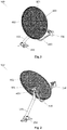
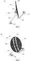
- Figures 1, 2 and 3 show a parabolic antenna (100) with a base (200), a mounting pole (300), head unit (400), rear structure (500), support pole (600) and low noise converter (700), usual in the state of the art and to the skilled in the art, not demanding, therefore, greater details.
- a parabolic antenna (100) according to the present utility model with a reflector (800) being made in a single piece, fastened to the rear structure (500) of the parabolic antenna (100) by means of a fastening unit (801), and having a reinforcement edge (802) facing away from the concavity of the reflector (800), and made in a rolled form ( figure 8 ) or in one or two levels ( figure 9 ) in the peripheral region of the reflector (800).
- parabolic antenna (100) having the reflector (800) according to the present utility model does not require structural ribs and bearing frames, thus being lighter and having lower manufacturing cost in comparison to known screen antennas.
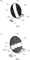
- the reflector (800) can be equipped with one or more non-perforated or smooth sections (803), in random directions, for example, vertical and/or horizontal, which preferably pass over the fastening unit (801), as can be inferred from figures 4 , 5 , 6 and 7 .
- the constructive disposition according to the present utility model surpasses the state of the art, being an object of practical use, perfectly susceptible of industrial application, comprising a new disposition, involving inventive step and resulting in functional improvement in its use, providing a parabolic antenna (100) with a self-structured reflector (800) made in a single piece in laminated expanded screen, and having a perfectly parabolic shape.
Landscapes
- Physics & Mathematics (AREA)
- Electromagnetism (AREA)
- Engineering & Computer Science (AREA)
- Manufacturing & Machinery (AREA)
- Aerials With Secondary Devices (AREA)
- Details Of Aerials (AREA)
Applications Claiming Priority (2)
| Application Number | Priority Date | Filing Date | Title |
|---|---|---|---|
| BR202014013528-1U BR202014013528Y1 (pt) | 2014-06-04 | 2014-06-04 | antena parabólica com refletor autoestruturado |
| PCT/BR2015/000082 WO2015184518A1 (pt) | 2014-06-04 | 2015-05-29 | Antena parabólica com refletor auto estruturado |
Publications (2)
| Publication Number | Publication Date |
|---|---|
| EP3154129A1 true EP3154129A1 (de) | 2017-04-12 |
| EP3154129A4 EP3154129A4 (de) | 2017-12-20 |
Family
ID=54765882
Family Applications (1)
| Application Number | Title | Priority Date | Filing Date |
|---|---|---|---|
| EP15802943.9A Withdrawn EP3154129A4 (de) | 2014-06-04 | 2015-05-29 | Parabolantenne mit selbststrukturiertem reflektor |
Country Status (15)
| Country | Link |
|---|---|
| US (1) | US10038250B2 (de) |
| EP (1) | EP3154129A4 (de) |
| JP (1) | JP2017518009A (de) |
| KR (1) | KR20170010373A (de) |
| CN (1) | CN206962023U (de) |
| AR (1) | AR104663A4 (de) |
| BR (1) | BR202014013528Y1 (de) |
| CA (1) | CA2947777C (de) |
| CL (1) | CL2016002981U1 (de) |
| EC (1) | ECSMU16090396U (de) |
| MX (1) | MX2016015855A (de) |
| PE (1) | PE20161518Z (de) |
| RU (1) | RU175124U1 (de) |
| UY (1) | UY4573U (de) |
| WO (1) | WO2015184518A1 (de) |
Families Citing this family (1)
| Publication number | Priority date | Publication date | Assignee | Title |
|---|---|---|---|---|
| EP3834252A4 (de) * | 2018-10-12 | 2022-05-25 | CommScope Technologies LLC | Flexible radomstrukturen |
Family Cites Families (30)
| Publication number | Priority date | Publication date | Assignee | Title |
|---|---|---|---|---|
| US2471828A (en) | 1944-07-04 | 1949-05-31 | Skydyne Inc | Parabolic antenna |
| US2997712A (en) | 1957-06-14 | 1961-08-22 | Donald S Kennedy | Antenna reflector construction |
| US3150030A (en) * | 1960-04-06 | 1964-09-22 | Raytheon Co | Laminated plastic structure |
| US3234550A (en) | 1961-06-12 | 1966-02-08 | Washington Aluminum Company In | Thin skinned parabolic reflector with radial ribs |
| US3397399A (en) | 1966-02-07 | 1968-08-13 | Goodyear Aerospace Corp | Collapsible dish reflector |
| FR2117807B1 (de) * | 1970-12-11 | 1973-12-28 | Girondon Michel | |
| US4378561A (en) | 1981-01-15 | 1983-03-29 | Hibbard Robert J | Parabolic reflector antenna |
| US4801946A (en) * | 1983-01-26 | 1989-01-31 | Mark Antenna Products, Inc. | Grid antenna |
| JPS59211303A (ja) * | 1983-05-16 | 1984-11-30 | Maspro Denkoh Corp | 高周波の通信信号用反射器 |
| JPS6045507U (ja) * | 1983-09-07 | 1985-03-30 | 住友電気工業株式会社 | パラボラアンテナ |
| JPS6057704A (ja) * | 1983-09-08 | 1985-04-03 | Sumitomo Electric Ind Ltd | オフセット型アンテナの楕円反射板製造方法 |
| US4578682A (en) | 1984-03-20 | 1986-03-25 | Raydx Satellite Systems, Ltd. | Antenna dish |
| US4568945A (en) | 1984-06-15 | 1986-02-04 | Winegard Company | Satellite dish antenna apparatus |
| EP0196607B1 (de) * | 1985-03-25 | 1991-04-24 | Kabushiki Kaisha Toshiba | Empfangsanordnung für Satellitensendungen |
| US4647943A (en) | 1985-03-29 | 1987-03-03 | General Instrument Corporation | Mesh dish antenna and hub |
| US4916459A (en) * | 1986-03-19 | 1990-04-10 | Hitachi, Ltd. | Parabolic antenna dish |
| JP2750592B2 (ja) * | 1989-01-20 | 1998-05-13 | 株式会社柏原機械製作所 | パラボラアンテナ用金属デイッシュ縁端面のカール方法およびカール型 |
| JPH0496114U (de) * | 1991-01-21 | 1992-08-20 | ||
| JPH05235630A (ja) * | 1992-02-18 | 1993-09-10 | Bridgestone Corp | パラボラアンテナ用のリフレクター |
| US5291212A (en) * | 1992-09-01 | 1994-03-01 | Andrew Corporation | Grid-type paraboloidal microwave antenna |
| JP3085512B2 (ja) * | 1993-12-24 | 2000-09-11 | 日本アンテナ株式会社 | パラボラアンテナ用ベースおよびパラボラアンテナ |
| US5421376A (en) * | 1994-01-21 | 1995-06-06 | Lockheed Missiles & Space Co., Inc. | Metallized mesh fabric panel construction for RF reflector |
| US5894290A (en) * | 1996-10-09 | 1999-04-13 | Espey Mfg. & Electronics Corp. | Parabolic rod antenna |
| US6188370B1 (en) * | 1999-06-24 | 2001-02-13 | California Amplifier, Inc. | Grid antennas and methods with efficient grid spacing |
| AU2001278672B2 (en) * | 2000-08-01 | 2004-07-15 | Tata Institute Of Fundamental Research | Preloaded parabolic dish antenna and the method of making it |
| WO2002018127A1 (en) * | 2000-08-28 | 2002-03-07 | Sakase Adtech Co., Ltd. | Composite material, formed product, and prepreg |
| JP2006074504A (ja) * | 2004-09-02 | 2006-03-16 | Mitsubishi Electric Corp | アンテナリフレクタおよびその製造方法 |
| TW200952261A (en) * | 2008-06-06 | 2009-12-16 | Azure Shine Int Inc | Manufacturing method of a satellite dish antenna that integrally displays trademark by visual contrast of hollw hole and the structure thereof |
| TW201112494A (en) * | 2009-09-25 | 2011-04-01 | Microelectronics Tech Inc | Assembly of clamping mechanism and LNB and disk antenna using the same |
| JP5693290B2 (ja) * | 2011-02-24 | 2015-04-01 | 三菱電機株式会社 | アンテナリフレクタの製造方法 |
-
2014
- 2014-06-04 BR BR202014013528-1U patent/BR202014013528Y1/pt active IP Right Grant
-
2015
- 2015-05-28 AR ARM150101683U patent/AR104663A4/es active IP Right Grant
- 2015-05-29 EP EP15802943.9A patent/EP3154129A4/de not_active Withdrawn
- 2015-05-29 KR KR1020167033612A patent/KR20170010373A/ko not_active Ceased
- 2015-05-29 RU RU2016148873U patent/RU175124U1/ru active
- 2015-05-29 PE PE2016002220U patent/PE20161518Z/es active IP Right Grant
- 2015-05-29 JP JP2017516009A patent/JP2017518009A/ja active Pending
- 2015-05-29 CN CN201590000662.7U patent/CN206962023U/zh not_active Expired - Fee Related
- 2015-05-29 CA CA2947777A patent/CA2947777C/en active Active
- 2015-05-29 MX MX2016015855A patent/MX2016015855A/es unknown
- 2015-05-29 WO PCT/BR2015/000082 patent/WO2015184518A1/pt not_active Ceased
- 2015-05-29 US US15/310,211 patent/US10038250B2/en active Active
- 2015-05-29 UY UY0001004573U patent/UY4573U/es active IP Right Grant
-
2016
- 2016-11-22 CL CL2016002981U patent/CL2016002981U1/es unknown
- 2016-11-28 EC ECIEPI201690396U patent/ECSMU16090396U/es unknown
Also Published As
| Publication number | Publication date |
|---|---|
| BR202014013528U2 (pt) | 2016-10-18 |
| ECSMU16090396U (es) | 2018-06-30 |
| JP2017518009A (ja) | 2017-06-29 |
| PE20161518Z (es) | 2017-01-15 |
| AR104663A4 (es) | 2017-08-09 |
| BR202014013528Y1 (pt) | 2018-11-06 |
| MX2016015855A (es) | 2017-06-06 |
| EP3154129A4 (de) | 2017-12-20 |
| UY4573U (es) | 2016-01-08 |
| WO2015184518A8 (pt) | 2017-06-15 |
| KR20170010373A (ko) | 2017-01-31 |
| CA2947777C (en) | 2021-06-08 |
| WO2015184518A1 (pt) | 2015-12-10 |
| US20170162946A1 (en) | 2017-06-08 |
| RU175124U1 (ru) | 2017-11-21 |
| CN206962023U (zh) | 2018-02-02 |
| CA2947777A1 (en) | 2015-12-10 |
| US10038250B2 (en) | 2018-07-31 |
| CL2016002981U1 (es) | 2017-07-14 |
Similar Documents
| Publication | Publication Date | Title |
|---|---|---|
| CA2947777C (en) | Parabolic antenna with self-structured reflector | |
| CN205249476U (zh) | 防水喇叭 | |
| CN107521659A (zh) | 一种多功能翼面前缘结构 | |
| CN202391041U (zh) | 天花板及其安装结构 | |
| CN202831513U (zh) | 一种墙壁装饰架 | |
| CN110359620A (zh) | 一种大堂空间大波浪铝板模块化安装结构 | |
| CN209653385U (zh) | W形铝模板 | |
| CN203927803U (zh) | 凸起拉伸冲压型可调角度的舱顶灯支架 | |
| CN201437685U (zh) | 百叶装置 | |
| CN203435143U (zh) | 多功能绿色环保高性能高音扬声器 | |
| CN207705386U (zh) | 一种天线罩 | |
| CN110877007A (zh) | 一种建筑工程用快速筛沙装置 | |
| CN207974236U (zh) | 厨房整体框架 | |
| CN202841497U (zh) | 用于微型扬声器装置的振翼装置 | |
| CN219055607U (zh) | 新型一体式蜂窝板 | |
| CN206864629U (zh) | 一种便于安装的电视平板天线 | |
| CN213390551U (zh) | 一种玻璃钢天幕 | |
| CN105276541A (zh) | 凸起拉伸冲压型可调角度的舱顶灯支架 | |
| CN204081111U (zh) | 无框架轻质空间吸声体 | |
| CN210421596U (zh) | 一种大堂空间大波浪铝板模块化安装结构 | |
| CN209245685U (zh) | 一种铝型材罗马柱盖 | |
| CN207553478U (zh) | 一种装配式内墙面轻质饰面板收口结构 | |
| CN203978204U (zh) | 铜门 | |
| CN202077076U (zh) | 一种滑轨弹簧固定结构 | |
| CN207959659U (zh) | 装配式多边形天花板 |
Legal Events
| Date | Code | Title | Description |
|---|---|---|---|
| STAA | Information on the status of an ep patent application or granted ep patent |
Free format text: STATUS: THE INTERNATIONAL PUBLICATION HAS BEEN MADE |
|
| PUAI | Public reference made under article 153(3) epc to a published international application that has entered the european phase |
Free format text: ORIGINAL CODE: 0009012 |
|
| STAA | Information on the status of an ep patent application or granted ep patent |
Free format text: STATUS: REQUEST FOR EXAMINATION WAS MADE |
|
| 17P | Request for examination filed |
Effective date: 20161201 |
|
| AK | Designated contracting states |
Kind code of ref document: A1 Designated state(s): AL AT BE BG CH CY CZ DE DK EE ES FI FR GB GR HR HU IE IS IT LI LT LU LV MC MK MT NL NO PL PT RO RS SE SI SK SM TR |
|
| AX | Request for extension of the european patent |
Extension state: BA ME |
|
| RIN1 | Information on inventor provided before grant (corrected) |
Inventor name: ABREU, JOAO ALEXANDRE DE Inventor name: ABREU, JOAO DO ESPIRITO SANTO |
|
| DAV | Request for validation of the european patent (deleted) | ||
| DAX | Request for extension of the european patent (deleted) | ||
| A4 | Supplementary search report drawn up and despatched |
Effective date: 20171122 |
|
| RIC1 | Information provided on ipc code assigned before grant |
Ipc: H01Q 19/13 20060101ALI20171116BHEP Ipc: H01Q 15/14 20060101ALI20171116BHEP Ipc: H01Q 15/16 20060101AFI20171116BHEP |
|
| STAA | Information on the status of an ep patent application or granted ep patent |
Free format text: STATUS: EXAMINATION IS IN PROGRESS |
|
| 17Q | First examination report despatched |
Effective date: 20210208 |
|
| STAA | Information on the status of an ep patent application or granted ep patent |
Free format text: STATUS: THE APPLICATION IS DEEMED TO BE WITHDRAWN |
|
| 18D | Application deemed to be withdrawn |
Effective date: 20241203 |