EP3153868A1 - Wind direction meter, wind direction and flow meter, and movement direction meter - Google Patents
Wind direction meter, wind direction and flow meter, and movement direction meter Download PDFInfo
- Publication number
- EP3153868A1 EP3153868A1 EP15802749.0A EP15802749A EP3153868A1 EP 3153868 A1 EP3153868 A1 EP 3153868A1 EP 15802749 A EP15802749 A EP 15802749A EP 3153868 A1 EP3153868 A1 EP 3153868A1
- Authority
- EP
- European Patent Office
- Prior art keywords
- wind
- conductor
- sensor
- temperature
- thermoelectric conversion
- Prior art date
- Legal status (The legal status is an assumption and is not a legal conclusion. Google has not performed a legal analysis and makes no representation as to the accuracy of the status listed.)
- Withdrawn
Links
Images









Classifications
-
- G—PHYSICS
- G01—MEASURING; TESTING
- G01P—MEASURING LINEAR OR ANGULAR SPEED, ACCELERATION, DECELERATION, OR SHOCK; INDICATING PRESENCE, ABSENCE, OR DIRECTION, OF MOVEMENT
- G01P13/00—Indicating or recording presence, absence, or direction, of movement
- G01P13/0006—Indicating or recording presence, absence, or direction, of movement of fluids or of granulous or powder-like substances
- G01P13/006—Indicating or recording presence, absence, or direction, of movement of fluids or of granulous or powder-like substances by using thermal variables
-
- G—PHYSICS
- G01—MEASURING; TESTING
- G01P—MEASURING LINEAR OR ANGULAR SPEED, ACCELERATION, DECELERATION, OR SHOCK; INDICATING PRESENCE, ABSENCE, OR DIRECTION, OF MOVEMENT
- G01P13/00—Indicating or recording presence, absence, or direction, of movement
- G01P13/02—Indicating direction only, e.g. by weather vane
-
- G—PHYSICS
- G01—MEASURING; TESTING
- G01P—MEASURING LINEAR OR ANGULAR SPEED, ACCELERATION, DECELERATION, OR SHOCK; INDICATING PRESENCE, ABSENCE, OR DIRECTION, OF MOVEMENT
- G01P5/00—Measuring speed of fluids, e.g. of air stream; Measuring speed of bodies relative to fluids, e.g. of ship, of aircraft
- G01P5/10—Measuring speed of fluids, e.g. of air stream; Measuring speed of bodies relative to fluids, e.g. of ship, of aircraft by measuring thermal variables
-
- G—PHYSICS
- G01—MEASURING; TESTING
- G01P—MEASURING LINEAR OR ANGULAR SPEED, ACCELERATION, DECELERATION, OR SHOCK; INDICATING PRESENCE, ABSENCE, OR DIRECTION, OF MOVEMENT
- G01P5/00—Measuring speed of fluids, e.g. of air stream; Measuring speed of bodies relative to fluids, e.g. of ship, of aircraft
- G01P5/10—Measuring speed of fluids, e.g. of air stream; Measuring speed of bodies relative to fluids, e.g. of ship, of aircraft by measuring thermal variables
- G01P5/12—Measuring speed of fluids, e.g. of air stream; Measuring speed of bodies relative to fluids, e.g. of ship, of aircraft by measuring thermal variables using variation of resistance of a heated conductor
Definitions
- the present invention relates to a wind direction meter, a wind direction/flow meter, and a movement direction meter.
- the wind direction meter As a conventional wind direction meter, there is a vane-type wind direction meter which uses the same principles as a weathervane (e.g., refer to PTL1).
- the wind direction meter is provided with a rotary shaft supported by a bearing, and a vane (arrow feather) which receives the wind and is rotatable around the rotary shaft, and indicates the wind direction by the direction in which the vane is oriented.
- the aforementioned conventional wind direction meter when measuring the wind direction, the aforementioned conventional wind direction meter generates friction in the mechanically movable parts constituted by the bearing and the rotary shaft.
- the conventional wind direction meter can detect the wind direction of a comparatively high wind speed, there has been difficulty in detecting the wind direction of a weak wind such as an indoor airflow.
- wind direction meters and wind direction/flow meters are desired to have the ability of detecting the direction of a weak wind.
- movement direction meters which use a wind direction meter for measuring the movement direction of an object to be moved, are also desired to have the ability of detecting the direction of a weak wind.
- the present invention has an object to provide a wind direction meter, a wind direction/flow meter, and a movement direction meter, which are capable of detecting the direction of a weak wind.
- the wind direction meter of the subject matter recited in claim 1 is a wind direction meter having a first surface (2a) and measuring a direction of a wind flowing above the first surface (2a), and has the following features.
- the wind direction meter includes: a plurality of sensors (2) each formed with the first surface and provided with: a thermoelectric conversion element (21, 21A, 21B, 370) having a first conductor (21a, 250a) that has a first end (21aa, 250aa) and a second end (21ab, 250ab) opposite to the first end made of a metal or a semiconductor, and having a second conductor (21b, 250b) that has a first end (21ba, 250ba) and a second end (21bb, 250bb) opposite to the first end made of a metal or a semiconductor different from the first conductor, the first conductor and the second conductor being serially connected to each other, and the first ends (21aa, 21b
- the wind direction meter In the wind direction meter, when the surrounding air, whose temperature has been changed by the temperature changing unit, is moved by the wind to cause a temperature difference between the first end and the second end of the respective first conductor and the second conductor, the outputs are ensured to be generated in conformity with the temperature difference, and the outputs, which are generated when the wind flows in a predetermined direction, have values different from each other; and a wind direction calculation unit (3) is provided for calculating a direction of the wind on the basis of a difference between the values of the outputs generated in each of the plurality of sensors.
- thermoelectric conversion element which does not have mechanically movable parts
- a wind direction/flow meter of the subject matter recited in claim 5 is a wind direction/flow meter which includes the wind direction meter according to claim 1.
- the wind direction calculation unit also configures a flow meter for calculating a wind volume on the basis of the values of the outputs. Since this configuration, includes the wind direction meter recited in claim 1, the wind direction of a weak wind can be detected.
- a movement direction meter of the subject matter recited in claim 6 has a first surface and arranged in a moving body (50) to measure a movement direction of the moving body by measuring a wind relatively generated to the moving body, the wind being generated above the first surface when the moving body moves, and has the following features.
- the movement direction meter includes: a plurality of sensors (2) each formed with the first surface and provided with: a thermoelectric conversion element (21, 21A, 21B, 370) having a first conductor (21a, 250a) that has a first end (21aa, 250aa) and a second end (21ab, 250ab) opposite to the first end and is made of a metal or a semiconductor, and having a second conductor (21b, 250b) that has a first end (21ba, 250ba) and a second end (21bb, 250bb) opposite to the first end and is made of a metal or a semiconductor different from the first conductor, the first conductor and the second conductor being serially connected to each other, and the first ends (21aa, 21ba, 250aa, 250ba) on mutually connected side of the first conductor and the second conductor, and the second end (21ab, 250ab) of the first conductor, and the second end (21bb, 250bbb)
- the outputs are ensured to be generated in conformity with the temperature difference; and the outputs, which are generated when the wind flows in a predetermined direction, have values different from each other; and a movement direction calculation unit (3A) is provided for calculating a movement direction of the moving body on the basis of a difference between the values of the outputs generated in each of the plurality of sensors.
- the wind direction is detected by using a thermoelectric conversion element which does not have mechanically movable parts.
- the wind direction meter 1 is a device which has a first surface 2a, measures the direction of the wind flowing above the first surface 2a, and, as shown in Fig. 1 , has a plurality of sensors 2, a control unit 3, and a display unit 4. As an example, the wind direction meter 1 is configured to have eight sensors 2.
- the plurality of sensors 2 are each configured by a sheet-like multilayer substrate having the first surface 2a and a second surface 2b opposite to the first surface 2a. As shown in Figs. 1 and 2 , the plurality of sensors 2 are each provided to a plane 5a of a fixing member 5, with the second surface 2b being adhered to the plane 5a of the fixing member 5. Specifically, in the present embodiment, the entirety of each second surface 2b of the sensor 2 is covered with the fixing member 5. Further, the plurality of sensors 2 are disposed in a manner of being offset from each other in the rotation direction centered on an axis perpendicular to the plane 5a.
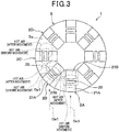
- the plurality of sensors 2 are disposed at different positions on the circumference (refer to the dashed line S1 in Fig. 2 ) centered on the axis perpendicular to the plane 5a. Specifically, eight sensors 2 are disposed at even intervals on a circumference S1.
- the wind direction meter 1 can calculate the direction of the wind in 16 directions (refer to the arrows Da1, Da2, Db1, ..., Dh2 of Fig. 2 ) in the radial direction of the circle having the circumference S1.
- the 16 directions include directions substantially coinciding with each other (e.g., the arrows Da1 and De2 of Fig. 2 coincide with each other).
- the directions of the wind which can be measured in the wind direction meter 1 of the present embodiment are substantively eight directions.
- the plurality of sensors 2 are each configured by two thermoelectric conversion elements 21 (a first thermoelectric conversion element 21A and a second thermoelectric conversion element 21B) and a heater 22.
- the two thermoelectric conversion elements 21 are disposed being interposed by the heater 22 therebetween, and are serially connected via wiring (back surface patterns 29 described later).
- the two thermoelectric conversion elements 21 and the heater 22 are disposed in the order of the first thermoelectric conversion element 21A, the heater 22, and the second thermoelectric conversion element 21B in a direction parallel to the first surface 2a and the second surface 2b of the sensor 2.
- the sensor 2 is arranged in the plane 5a of the fixing member 5 so that the first and second thermoelectric conversion elements 21A and 21B are located on both sides of the heater 22 in a direction parallel to the flow direction (refer to the arrows Da1, Da2 of Fig. 5 ) of the wind as an object to be detected.
- the senor 2 is configured by a multilayer substrate which is an integration of an insulating base material 23, a front surface protective member 24 having the first surface 2a, and a back surface protective member 25.
- the thermoelectric conversion elements 21 and the heater 22 are arranged inside the multilayer substrate.
- each thermoelectric conversion element 21 has a first interlayer connection member 21a and a second interlayer connection member 21b, and generates an electromotive force, i.e., a voltage, according to the temperature difference between both ends 21aa, 21ba, 21ab, 21bb of the respective first and second interlayer connection members 21a and 21b.
- the first and second interlayer connection members 21a and 21b are serially connected via wiring (front surface patterns 28 described later), and are electrically connected to the control unit 3.
- the first interlayer connection member 21a is made of a metal or semiconductor
- the second interlayer connection member 21b is made of a different metal or semiconductor than the first interlayer connection member 21a.
- the first interlayer connection member 21a corresponds to the first conductor in the claims
- the second interlayer connection member 21b corresponds to the second conductor in the claims.
- first ends 21aa, 21ba connected to each other on one side of the first and second interlayer connection members 21a, 21b are respectively opposed to a second end 21ab opposite to the first end 21aa of the first interlayer connection member 21a and a second end 21bb opposite to the first end 21ba of the second interlayer connection member 21b.
- the first ends 21aa, 21ba are disposed so as to be respectively opposed to and in alignment with the second ends 21ab, 21bb in a direction perpendicular to the directions Da1, Da2 in which the wind flows.
- the first ends 21aa, 21ba are disposed on the first surface 2a side of the sensor 2
- the second ends 21ab, 21bb are disposed on the second surface 2b side of the sensor 2.
- thermoelectric conversion elements 21 are connected in series via wiring (back surface pattern 29 described later) in each of the plurality of sensors 2.
- the electromotive force of the sensor 2 can be intensified, and thus high sensitivity can be imparted to the sensor 2.
- the heater 22 is a heat source for generating heat, and is configured by a heating wire, such as a nichrome wire, which generates heat when current is applied.
- the heater 22 is provided as a temperature changing unit for changing ambient temperature by generating heat.
- the heater 22 is electrically connected to the control unit 3.
- a cooler which changes the ambient temperature by absorbing heat may be used as the temperature changing unit for changing ambient temperature.
- the insulating base material 23 is made of a thermoplastic resin film, which is rectangular in plan view, typified such as by a polyether ether ketone (PEEK), polyetherimide (PEI), or liquid crystal polymer (LCP).
- PEEK polyether ether ketone
- PEI polyetherimide
- LCP liquid crystal polymer
- First and second via holes 26, 27 of the present embodiment each have a cylindrical shape with a fixed diameter and extend from the first surface 2a to the second surface 2b, but may have a tapered shape with the diameter becoming smaller from the first surface 2a towards the second surface 2b. Further, the first and second via holes 26, 27 may each have a tapered shape with the diameter becoming smaller from the second surface 2b towards the first surface 2a, or may be formed in a rectangular tube.
- the first interlayer connection member 21a is disposed in the first via hole 26, and the second interlayer connection member 21b is disposed in the second via hole 27. That is, the first and second interlayer connection members 21a, 21b are alternately disposed in the insulating base material 23.
- first and second interlayer connection members 21a, 21b are disposed in the first and second via holes 26, 27, high sensitivity of the first and second interlayer connection members 21a, 21b is ensured by appropriately changing the number, diameter, interval, and the like of the first and second via holes 26, 27.
- the electromotive force of the sensor 2 can be increased in this way, and a high sensitivity is imparted to the sensor 2.
- the first and second interlayer connection members 21a, 21b are made of different metals or semiconductors in order to bring about the Seebeck effect.
- the first interlayer connection member 21a is made of a solid phase sintered metal compound in order to maintain a crystal structure of a plurality of metal atoms forming P-type Bi-Sb-Te alloy powder prior to sintering.
- the second layer connection member 21b is made of a solid phase sintered metal compound in order to maintain a crystal structure of a plurality of metal atoms forming N-type Bi-Te alloy powder prior to sintering.
- the metal for forming each of the first and second interlayer connection members 21a, 21b is a sintered alloy that is sintered in a state where the plurality of metal atoms maintain the crystal structure of the metal atoms. This enables increase in the electromotive force generated by the first and second interlayer connection members 21a, 21b which are alternately connected in series, and thus a high sensitivity is imparted to the sensor 2.
- the wind direction meter 1 uses the highly sensitive sensor 2. Accordingly, use of the sensor 2 enables detection of the direction of a weak wind flowing above the first surface 2a.
- the front surface 23a of the insulating base materials 23 is arranged with the front surface protective member 24 formed of a thermoplastic resin film, which is rectangular in plan view, typified such as by a polyether ether ketone (PEEK), polyetherimide (PEI), and liquid crystal polymer (LCP).
- the front surface protective member 24 is ensured to have the same shape in plan view as that of the insulating base material 23.
- the front surface protective member 24 has a surface 24a opposing the insulating base material 23 and formed with a plurality of front surface patterns 28 obtained by patterning a copper foil, etc. so as to be spaced apart from each other.
- the front surface patterns 28 are appropriately electrically connected to the respective first and second interlayer connection members 21a, 21b.
- the first and second interlayer connection members 21a, 21b of each pair 21c are connected to the same single front surface pattern 28.
- the first and second interlayer connection members 21a, 21b of each pair 21c are electrically connected to each other via the front surface pattern 28.
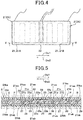
- the pair 21c is formed by a first interlayer connection member 21a and a second interlayer connection member 21b that are adjacent to each other along the longitudinal direction (the left-right direction in Fig. 4 ) of the insulating base material 23.
- the insulating base material 23 has a back surface 23b which is opposite to the front surface 23a.
- the back surface 23b is arranged with the back surface protective member 25 which is rectangular in plan view and formed of a thermoplastic resin film such as of polyether ether ketone (PEEK), polyetherimide (PEI), and liquid crystal polymer (LCP).
- the back surface protective member 25 has a length in the longitudinal direction of the insulating base material 23 longer than the insulating base material 23, and is disposed on the back surface 23b of the insulating base material 23 so that both end parts in the longitudinal direction project from the insulating base material 23.
- the back surface protective member 25 has a first surface 25a opposing the insulating base material 23 and formed with a plurality of back surface patterns 29 obtained by patterning a copper foil, etc. so as to be spaced apart from each other. Each of the back surface patterns 29 is appropriately electrically connected to the corresponding first and second interlayer connection members 21a, 21b.
- the first interlayer connection member 21a of one of the pairs 21c and the second interlayer connection member 21b of the other pair 21c are connected to the same single back surface pattern 29.
- the first and second interlayer connection members 21a, 21b are electrically connected to each other via the same single back surface pattern 29.
- the pairs 21c are serially connected as shown by the dashed line in Fig. 4 .
- the dashed line in Fig. 4 shows a plurality of serially connected pairs 21c and the wiring.
- thermoelectric conversion element 21A In the heater 22 of each sensor 2, a heating wire 22a is buried inside the insulating base material 23.
- the back surface pattern 29 is formed under the heater 22 of the sensor 2 so as to straddle the heater 22.
- the first and second interlayer connection members 21a, 21b of the first thermoelectric conversion element 21A are serially connected to the first and second interlayer connection members 21a, 21b of the second thermoelectric conversion element 21B via the back surface patterns 29.
- thermoelectric conversion elements 21 are linearly symmetric with respect to the heater 22 provided as an axis between the two thermoelectric conversion elements 21.
- the first and second thermoelectric conversion elements 21A and 21B have the same basic structure, such as of having the same shape and magnitude, and also have the same distance from the heater 22. Further, between the first and second thermoelectric conversion elements 21A and 21B, the connection sequence of the first and second interlayer connection members 21a and 21b is reversed.
- thermoelectric conversion elements 21A and 21B of the present embodiment a reverse relationship is established in terms of the level of temperature and the polarity of electromotive force in the respective first ends 21aa, 21ba and second ends 21ab, 21bb of the first and second interlayer connection members 21a, 21b.
- first ends 21aa, 21ba of the first and second interlayer connection members 21a, 21b have a higher temperature than the second ends 21ab, 21bb in both of the two thermoelectric conversion elements 21, the two thermoelectric conversion elements 21 generate electromotive forces having different polarities (e.g., one is positive and the other is negative).
- thermoelectric conversion elements 21 generate electromotive forces having different polarities. Further, if the first ends 21aa, 21ba have a higher temperature than the second ends 21ab, 21bb in the first thermoelectric conversion element 21A, and the first ends 21aa, 21ba have a lower temperature than the second ends 21ab, 21bb in the second thermoelectric conversion element 21B, the two thermoelectric conversion elements 21 generate electromotive forces having the same polarity.
- thermoelectric conversion elements 21A and 21B electromotive forces of the same polarity are generated when a reverse relationship is established between the first and second thermoelectric conversion elements 21A and 21B, in terms of the level of temperature at the first ends 21aa, 21ba and the second ends 21ab, 21bb.
- the configuration of the sensor 2 of the present embodiment is as described above.
- the first ends 21aa, 21ba of the first and second interlayer connection members 21a, 21b connected to each other are arranged on the first surface 2a side
- the second ends 21ab, 21bb thereof are arranged on the second surface 2b side. Therefore, if the temperature on the first surface 2a side is different from the temperature on the second surface 2b side in the sensors 2, the temperature at the first ends 21aa, 21ba of the first and second interlayer connection members 21a, 21b will be different from the temperature at the second ends 21ab, 21bb thereof.
- the temperature difference leads to generation of an electromotive force, the degree of which depends on the degree of difference in the temperature.
- the wind direction meter 1 of the present embodiment outputs the electromotive force as a sensor signal to the control unit 3.
- the electromotive force is changed when the aforementioned temperature difference is changed.
- the method uses the insulating base material 23 as shown in Fig. 6(a) .
- the insulating base material 23 is formed as follows.
- the insulating base material 23 to be used herein is embedded with a heater 22.
- a plurality of the first via holes 26 are formed in the insulating base material 23 by means of a drill, a laser, or the like.
- the first via holes 26 are filled with a first conductive paste 21d.
- the method (device) of filling the first via holes 26 with the first conductive paste 21d may be the method (device) described in Japanese Patent Application No. 2010-50356 filed by the present applicants.
- the insulating base material 23 is arranged on a holding table, via absorption paper, so that the back surface 23b is opposed to the absorption paper. Then, the first conductive paste 21d, while being melted, is filled in the first via holes 26. Thus, most of the organic solvent in the first conductive paste 21d is adsorbed by the absorption paper, and the alloy powder is arranged being in intimate contact with the first via hole 26.
- the absorption paper only has to be a material capable of adsorbing the organic solvent in the first conductive paste 21d, and may be generally used high quality paper.
- the first conductive paste 21d is a paste material obtained by adding an organic solvent, such as paraffin, having a melting point of 43°C, to a Bi-Sb-Te alloy powder in which the metal atoms maintain a predetermined crystal structure. Therefore, the first conductive paste 21d is filled in a state where the front surface 23a of the insulating base material 23 is heated to approximately 43°C.
- a plurality of the second via holes 27 are formed in the insulating base material 23 by means of a drill, laser, and the like.
- a second conductive paste 21e is filled in the second via holes 27.
- This process can be performed similarly to the process of filling the first conductive paste 21d. Namely, although not shown, after arranging the insulating base material 23 on the holding table, via the absorption paper, so that the back surface 23b is opposed to the absorption paper, the second conductive paste 21e is filled in the second via holes 27. Thus, most of the organic solvent in the second conductive paste 21e is adsorbed by the absorption paper, and the alloy powder is arranged being in intimate contact with the second via holes 27.
- the second conductive paste 21e is a pasted material obtained by adding an organic solvent, such as terpineol, having a melting point of room temperature, to a Bi-Te alloy powder in which the metal atoms different from those constituting the first conductive paste 21d maintain a predetermined crystal structure.
- the organic solvent constituting the second conductive paste 21e is one having a melting point lower than that of the organic solvent constituting the first conductive paste 21d.
- the second conductive paste 21e is filled in a state where the front surface 23a of the insulating base material 23 is maintained at room temperature. In other words, the filling of the second conductive paste 21e is performed in a state where the organic solvent contained in the first conductive paste 21d is solidified. Thus, the second conductive paste 21e is prevented from mixing into the first via holes 26.
- the state where the organic solvent contained in the first conductive paste 21d is solidified refers to the state where the organic solvent remains in the first via hole 26 without being adsorbed by the absorption paper in the process of filling the first conductive paste 21d.
- the method also uses the front surface protective member 24 and the back surface protective member 25 shown in (b) and (c) of Fig. 6 .
- These members are formed as follows. First, a copper foil, etc., is formed on each of the first surfaces 24a, 25a of the front surface protective member 24 and the back surface protective member 25, respectively, facing the insulating base material 23. Then, by appropriately patterning the copper foils, a plurality of front surface patterns 28 spaced apart from each other and a plurality of back surface patterns 29 spaced apart from each other are formed on the front surface protective member 24 and the back surface protective member 25, respectively.
- the back surface protective member 25, the insulating base material 23, and the front surface protective member 24 are laminated in this order to form a laminate 215.
- the laminate 215 is placed between a pair of press plates, not shown, followed by heating and pressing the laminate in a vacuum state from above and below in the lamination direction, thereby integrating the laminate.
- the first and the second conductive pastes 21d, 21e are solid-phase sintered to form the first and second interlayer connection members 21a, 21b, while performing heating and pressing so that the first and second interlayer connection members 21a, 21b are connected to the front surface patterns 28 and the back surface patterns 29, respectively, to thereby integrate the laminate 215.
- a cushioning material such as rock wool paper may be arranged between the laminate 215 and each of the press plates.
- the sensor 2 is produced as described above.
- the control unit 3 is the wind direction calculation unit for calculating the direction of the wind which is an object to be measured on the basis of a detection result of the sensors 2.
- the control unit 3 is an electronic control unit configured by a microcomputer, a memory as a storage section, and a peripheral circuit thereof, and performs a predetermined arithmetic processing according to a given program to control the operation of the display unit 4. Further, the control unit 3 functions as a unit for controlling the activation and deactivation of the heaters 22.
- the display unit 4 such a monitor, displays the wind direction calculated by the control unit 3.
- the fixing member 5 having a plane 5a serves as a member for fixing the plurality of sensors 2 in the plane 5a.
- the fixing member 5 of the present embodiment is formed of a material which transfers less heat than the air above the first surface 2a (or, the wind flowing above the first surface 2a) or the material for forming the sensor 2, and thus is formed of resin, for example.
- the heaters 22 in the plurality of (eight) sensors 2 are activated to generate heat.
- the first surface 2a side of the sensor 2 reaches a temperature in conformity with the temperature distribution of the air (wind) above the first surface 2a
- the second surface 2b side of the sensor 2 reaches a temperature in conformity with the temperature distribution of the fixing member 5.
- a temperature distribution is formed on the first surface 2a side and the second surface 2b of the sensor 2 side, in which an area closer to the heater 22 has a higher temperature.
- the structures of the two thermoelectric conversion elements 21 are linearly symmetric with respect to the heater 22 as an axis. Therefore, as shown in the isotherm of Fig.
- the sensor 2 of the present embodiment transmits the heat generated from the heater 22, when there is no wind, equally to both sides (two thermoelectric conversion elements 21) sandwiching the heater 22. Specifically, compared to the temperature generated when the distances from the heater 22 on the first and second surfaces 2a and 2b of the sensor 2 are the same, the temperature on the first surface 2a side where the wind passes becomes higher than the temperature on the second surface 2b side provided with the fixing member 5. As a result, the two corresponding first interlayer connection members 21a sandwiching the heater 22 and disposed in symmetric positions have equivalent temperature differences between both ends (the first end 21aa and the second end 21ab of Fig. 5 ).
- the two corresponding second interlayer connection members 21b sandwiching the heater 22 and disposed in symmetric positions have equivalent temperature differences between both ends (the first end 21aa and the second end 21ab of Fig. 5 ).
- the sensor 2 of the present embodiment is configured, as stated above, such that a reverse relationship is established in respect of the level of temperature and the polarity of electromotive force. Therefore, in the sensor 2 of the present embodiment, when there is no wind, the respective electromotive forces generated by the two thermoelectric conversion elements 21 are of equivalent magnitude and the polarities thereof are the reverse of each other. Thus, the entire electromotive force of the respective plurality of sensors 2 becomes zero. Similarly, the electromotive force of the plurality of sensors 2 becomes zero when there is no wind.
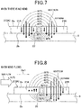
- the present embodiment is provided with the fixing member 5 configured by a material which hardly transfers heat, the interval of each isotherm is smaller, as shown in Fig. 7 , in the temperature distribution on the second surface 2b side of the sensor 2 than the temperature distribution on the first surface 2a side.
- the air (hereinafter, referred to as hot air) on the first surface 2a side in the surrounding air whose temperature has been changed by the heater 22 is moved in the direction (right direction of Fig. 8 ) parallel to the first surface 2a by the wind.
- the entirety of the second surface 2b of the sensor 2 is covered with the fixing member 5 as mentioned above, and thus the wind does not flow to the second surface 2b side of the sensor 2. Therefore, the second surface 2b side air of the hot air is not moved by the wind (or, is moved slowly compared to the air on the first surface 2a side). Therefore, as shown in Fig. 8 , when the wind flows over the wind direction meter 1 of the present embodiment, the temperature distribution is changed in the air (or the wind) on the first surface 2a side of the sensor 2.
- the first surface 2a side in the thermoelectric conversion element 21 on the right side of Fig. 8 will have a high temperature as shown in Fig. 8 , and further, the respective first ends 21aa, 21ba of the first and second interlayer connection members 21a, 21b will have a high temperature. Further, the first surface 2a side in the thermoelectric conversion element 21 on the left side of Fig. 8 will have a low temperature, and further, the respective first ends 21aa, 21ba of the first and second interlayer connection members 21a, 21b will have a low temperature. In this case, as stated above, the air of the second surface 2b side is not moved by the wind.
- thermoelectric conversion elements 21A and 21B the temperature will not change in the respective second ends 21ab, 21bb of the first and second interlayer connection members 21a, 21b of the two thermoelectric conversion elements 21 of Fig. 8 . Therefore, in the two thermoelectric conversion elements 21, temperature difference is caused between both ends 21aa, 21ba and 21ab, 21bb of the first and second interlayer connection members 21a, 21b. Moreover, the temperature level is reversed between the first and second thermoelectric conversion elements 21A and 21B.
- thermoelectric conversion elements 21 immediately after flow of the wind over each of the two thermoelectric conversion elements 21, temperature difference is caused between the first ends 21aa, 21ba of the first and second interlayer connection members 21a, 21b, and the second end 21ab of the first interlayer connection member 21a and the second end 21bb of the second interlayer connection member 21b.
- the sensor 2 generates a positive electromotive force in conformity with the temperature difference between both ends 21aa, 21ba and 21ab, 21bb.
- thermoelectric conversion elements 21 produce electromotive forces having the same polarity (positive), compared to the case when there is one thermoelectric conversion element 21, the electromotive force of the sensor 2 is intensified, and a high sensitivity can be imparted to the sensor 2.
- the sensor 2 When the wind flows in the direction (arrow Da2 of Fig. 2 ) opposite to Da1, the sensor 2 generates a negative electromotive force having an absolute value equivalent to that of the electromotive force generated when the wind flows in the direction of Da 1.
- each sensor 2 operates as described above. Next, a method of measuring the wind direction using the plurality of (eight) sensors 2 operating in this way will be described.
- the plurality of sensors 2 are disposed being offset from each other in the rotation direction centered on a line perpendicular to the plane 5a. Therefore, in the present embodiment, the plurality of sensors 2 generate electromotive forces of different values when the wind flows in a predetermined direction. Specifically, among the plurality of sensors 2, the sensor 2 above which the hot air has been moved by the wind over a wide range of the first surface 2a (the first ends 21aa, 21ba of the first and second interlayer connection members 21a, 21b) generates the electromotive force with a large absolute value. For example, as shown in Fig. 3 , in the case when the direction of the wind is the direction of the arrow Da1 of Fig.
- the hot air is transmitted over a wide range of the first surface 2a of the sensor 2A, and thus the absolute value of the electromotive force to be generated increases. Further, in this case, the hot air is transmitted over a narrower range in the sensor 2B compared to the sensor 2A, and thus the electromotive force to be generated decreases. Further, the hot air is transmitted over a further narrower range in the sensor 2C, and thus the electromotive force to be generated further decreases. Furthermore, the range over which the hot air that has been moved by the wind is transmitted to the first surface 2a depends upon to what extent the direction of the wind agrees with the direction of the row of the first thermoelectric conversion element 21A, the heater 22, the second and thermoelectric conversion element 21B for the respective sensors.
- the direction of the wind (the direction of Da1 when the electromotive force of the sensor 2A is positive and the maximum) can be measured.
- the electromotive force of the sensor 2 becomes negative.
- This design may be used to ensure one sensor 2 can measure the two directions (Da1 and Da2) opposite to each other.
- the sensors 2E, 2F, 2G, 2H may be omitted and may include only the sensors 2A, 2B, 2C, 2D. With this configuration as well, all the directions (Da1 to Dh2) which can be measured when provided with eight sensors 2 (2A to 2H) can be measured.
- the wind direction meter 1 of the present embodiment measures the direction of the wind, as an object to be measured, on the basis of the difference in the electromotive force generated in each of the plurality of sensors 2.
- the wind direction meter 1 of the present embodiment detects the wind direction using the sensor 2 having no mechanically movable parts, enabling detection of a weak wind. Coupled with this configuration, use of the sensor 2 having a high sensitivity in the wind direction meter 1 of the present embodiment specifically enables detection of the direction of a weak wind.
- An error with regards to the temperature difference between the first and second surfaces 2a and 2b may occur, for example, due to a change of the ambient environmental temperature.
- the sensor 2 of the present embodiment is configured, as stated above, such that a reverse relationship is established in respect of the level of temperature and the polarity of electromotive force between the first ends 21aa, 21ba and the second ends 21ab, 21bb of the respective first and second interlayer connection members 21a, 21b. Therefore, if the aforementioned error occurs, the electromotive forces generated by the two thermoelectric conversion elements 21 are of equivalent magnitude and the polarities thereof are reverse to each other. As a result, the entire electromotive force of the respective plurality of sensors 2 becomes zero. Therefore, the sensor 2 of the present embodiment does not have an adverse effect (has only a small effect) on the value of the electromotive force generated by the sensor 2 if the aforementioned error occurs due to a change of the ambient environmental temperature, for example.
- the wind direction meter 1 of the present embodiment has the first surface 2a and measures the direction of the wind flowing above the first surface 2a, and is characterized by the employment of the following plurality of sensors 2 and the control unit 3.
- the sensor 2 is formed with the first surface 2a, and includes the first interlayer connection member 21a made of a metal or semiconductor, and a second interlayer connection member 21b made of a different metal or semiconductor than the first interlayer connection member 21a.
- the sensor 2 is provided with a thermoelectric conversion element 21 for generating an electromotive force when a temperature difference occurs between the first ends 21aa, 21ba and the second ends 21ab, 21bb of the respective first and second interlayer connection members 21a, 21b.
- the sensor 2 generates an electromotive force, when the surrounding air whose temperature has been changed by the heater 22 is moved by the wind to cause a temperature difference between the first ends 21aa, 21ba and the second ends 21ab, 21bb of the first and second interlayer connection members 21a, 21b.
- the control unit 3 calculates the direction of the wind, as an object to be measured, on the basis of the difference in electromotive force generated in each of the plurality of sensors 2.
- the wind direction meter 1 of the present embodiment uses the thermoelectric conversion element 21 having no mechanically movable parts to detect the wind direction, the direction of a weak wind can be detected. Coupled with this configuration, use of the sensor 2 having a high sensitivity in the wind direction meter 1 of the present embodiment specifically enables detection of the direction of a weak wind.
- the sensor 2 is configured such that the two thermoelectric conversion elements 21 are disposed sandwiching the heater 22, while being serially connected to each other via wiring (back surface pattern 29). Furthermore, the sensor 2 is configured such that a reverse relationship is established in respect of the level of temperature and the polarity of electromotive force between the first ends 21aa, 21ba and the second ends 21ab, 21bb of the respective first and second interlayer connection members 21a, 21b.
- the wind direction meter 1 of the present embodiment can increase the electromotive force generated by the sensor 2 and impart a high sensitivity to the sensor 2, compared to the case where the thermoelectric conversion element 21 is disposed on only one side of the heater 22.
- the senor 2 is provided with the two thermoelectric conversion elements 21 (the first and second thermoelectric conversion elements 21A and 21B) and the heater 22.
- the sensor 2 may be provided with only one of the two thermoelectric conversion elements 21.
- the senor 2 is configured such that the two thermoelectric conversion elements 21 are disposed sandwiching the heater 22, while being serially connecting to each other via wiring (back surface pattern 29).
- the sensor 2 may be configured such that the two thermoelectric conversion elements 21 are independently electrically connected to the control unit 3.
- wiring for establishing connection with the control unit 3 must be provided for each of the two thermoelectric conversion elements 21.
- the sensor 2 has the aforementioned configuration (the configuration in which two thermoelectric conversion elements 21 are serially connected).
- a second embodiment of the present invention will be described.
- the heater 22 of the first embodiment has been changed to a Peltier element 320. Since the rest of the configuration is similar to the first embodiment, description is omitted herein.
- the wind direction meter 1 of the first embodiment is configured to include the heater 22 as the temperature changing unit, but the wind direction meter 1 according to the present embodiment is configured to include, as shown in Figs. 9 and 10 , a Peltier element 320 as the temperature changing unit.
- the wind direction meter 1 of the first embodiment is configured by covering the entirety of the second surface 2b of the sensor 2 with the fixing member 5 so that the wind does not flow to the second surface 2b side of the sensor 2.
- the present embodiment is configured such that the wind can flow to the second surface 2b side of the sensor 2 (not only the first surface 2a).
- a spacer is provided between each of the plurality of sensors 2 and the fixing member 5, and only a part of the second surface 2b is covered by the spacer in each of the plurality of sensors 2.
- the Peltier element 320 is a heat source which generates both heat and cold. As shown in Fig. 9 , the Peltier element 320 is formed on a multilayer substrate together with the first and second thermoelectric conversion elements 21A, 21B in each of the plurality of sensors 2. In the present embodiment, the Peltier element 320 has a structure similar to that of the first thermoelectric conversion element 21A. Namely, the Peltier element 320 includes a first interlayer connection member 21a and a second interlayer connection member 21b, with the first and second interlayer connection members 21a and 21b being serially connected to each other via wiring (front surface pattern 28), for electrical connection to the control unit 3.
- the first ends 21aa, 21ba of the respective first and second interlayer connection members 21a, 21b constituting the Peltier element 320 are disposed on the first surface 2a side of the sensor 2. Further, the second ends 21ab, 21bb of the respective first and second interlayer connection members 21a, 21b constituting the Peltier element 320 are disposed on the second surface 2b side of the sensor 2.
- the Peltier element 320 of the present embodiment when electric power is supplied to the first and second interlayer connection members 21a, 21b, heat is generated at the first ends 21aa, 21ba of the first and second interlayer connection members 21a, 21b, but heat is absorbed at the second ends 21ab, 21bb of the first and second interlayer connection members 21a, 21b. Therefore, as shown in Fig. 11 , in the Peltier element 320 of the present embodiment, when electric power is supplied to the first and second interlayer connection members 21a, 21b, the first surface 2a side of the sensor 2 generates heat, and the second surface 2b side of the sensor 2 absorbs heat.
- the Peltier element 320 includes the first and second interlayer connection members 21a, 21b with the first ends 21aa, 21ba serving as the first temperature changing unit being disposed on the first surface 2a to conduct heat generation or heat absorption. Further, the Peltier element 320 includes the first and second interlayer connection members 21a, 21b with the second ends 21ab, 21bb serving as the second temperature changing unit being disposed on the second surface 2b side to conduct heat generation or heat absorption which is not being conducted by the first temperature changing unit.
- the present embodiment may be configured to include a heater to serve as either the first temperature changing unit or the second temperature changing unit, and include a cooler as a separate member from the heater to serve as the other unit.
- first ends 21aa, 21ba of the respective first and second interlayer connection members 21a and 21b configuring the first and second thermoelectric conversion elements 21A, 21B are disposed on the first surface 2a side of the sensor 2.
- second ends 21ab, 21bb of the respective first and second interlayer connection members 21a and 21b configuring the first and second thermoelectric conversion elements 21A, 21B are disposed on the second surface 2b side of the sensor 2.
- the sensor 2 of the present embodiment can be produced by the method of producing the sensor 2 described in the first embodiment, with a change in that the region for configuring the Peltier element 320 in the sensor 2 is electrically independent of the first thermoelectric conversion element 21A, while having the same structure as the first thermoelectric conversion element 21A.
- the Peltier element 320 is activated to generate heat on the first surface 2a side of the sensor 2 and to absorb heat on the second surface 2b side of the sensor 2.
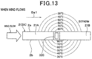
- the temperature distribution shown with the isotherm of Fig. 11 is formed in the air (or the wind) on the first surface 2a side of the sensor 2, while forming the temperature distribution shown with the isotherm of Fig. 11 in the fixing member 5 on the second surface 2b side of the sensor 2, with the transmission of the heat of the Peltier element 320.
- the present embodiment uses the Peltier element 320 as the temperature changing unit, and thus, when there is no wind, the first surface 2a side of the sensor 2 will have a high temperature and the second surface 2b side of the sensor 2 will have a cool temperature, as shown in the isotherm of Fig. 11 , due to the absorption and generation of heat of the Peltier element 320.
- the first surface 2a side of the sensor 2 is formed with a temperature distribution in which an area closer to the Peltier element 320 has a higher temperature
- the second surface 2b side of the sensor 2 is formed with a temperature distribution in which an area closer to the Peltier element 320 has a lower temperature. Therefore, the closer the approach is to the Peltier element 320, the greater the temperature difference becomes between the first surface 2a side and the second surface 2b side.
- the structures of the two thermoelectric conversion elements 21 are linearly symmetric with respect to the Peltier element 320 as an axis. Therefore, in the sensor 2 of the present embodiment as well, when there is no wind, the heat generated from the Peltier element 320 is transmitted equally, as shown in the isotherm of Fig. 11 , to both sides (the two thermoelectric conversion elements 21) sandwiching the Peltier element 320.
- the temperature difference between both ends becomes equivalent in the two corresponding first and second interlayer connection members 21a, 21b symmetrically disposed sandwiching the Peltier element 320. Further, a reverse relationship is established in respect of the level of temperature and the polarity of electromotive force in the same manner as in the first embodiment. Thus, in the present embodiment as well, when there is no wind, the entirety of the electromotive force of the plurality of sensors 2 becomes zero.
- the temperature distribution shown by the isotherm of Fig. 12 is formed in the air (or the wind) on the first surface 2a side of the sensor 2, and the temperature distribution shown by the isotherm of Fig. 12 is formed in the air (or the wind) on the second surface 2b side of the sensor 2.
- the high temperature air hereinafter, referred to as the hot air
- the Peltier element 320 is moved by the wind in the direction (the right direction in Fig. 12 ) parallel to the first surface 2a in the same manner as in the first embodiment.
- the wind also flows as stated above to the second surface 2b side of the sensor 2, and thus the low temperature air (hereinafter, referred to as cold air) on the second surface 2b side in the surrounding air whose temperature has been changed by the Peltier element 320 is also moved in the direction parallel to the first surface 2a similarly to the hot air.
- cold air low temperature air
- the present embodiment when there is no wind, the present embodiment enables formation of a temperature distribution on the first surface 2a side of the sensor 2, as stated above, in which an area closer to the Peltier element 320 has a higher temperature, and enables formation of a temperature distribution on the second surface 2b side in which an area closer to the Peltier element 320 has a lower temperature.
- the closer the approach is to the Peltier element 320 the greater the temperature difference becomes between the first surface 2a side and the second surface 2b side.
- thermoelectric conversion element 21B when the temperature distribution of both surfaces 2a, 2b is shifted by the wind, a portion having a particularly large temperature difference in the temperature distribution is located in the second thermoelectric conversion element 21B which is located further downstream of the wind than the Peltier element 320 is. Therefore, in the second thermoelectric conversion element 21B, the temperature difference between both ends of the first and second interlayer connection members 21a, 21b becomes large compared to the case when there is no wind.
- the temperature difference between both ends of the first and second interlayer connection members 21a, 21b becomes small in the first thermoelectric conversion element 21A which is located further upstream of the wind than the Peltier element 320 is, compared to the case when there is no wind.
- a positive electromotive force is generated in the sensor 2, the positive electromotive force being a combination of the electromotive force produced by the first thermoelectric conversion element 21A and the electromotive force produced by the second thermoelectric conversion element 21B.
- the wind direction meter 1 of the present embodiment can measure the direction of the wind without being provided with a fixing member 5, even when the air on the second surface 2b side in the air whose temperature has been changed by the temperature changing unit is moved by the wind and the like as an object to be measured.
- a third embodiment of the present invention will be described.
- the configuration of the sensor 2 is changed from that of the first embodiment.
- the rest of the configuration is similar to the first embodiment, and thus description is omitted.
- a spacer is provided between each of the plurality of sensors 2 and the fixing member 5 so that the wind can also flow to the second surface 2b (not only the first surface 2a) side of the sensor 2.
- Fig. 15 is an enlarged view of a portion A surrounded by the dashed line of Fig. 14
- Figs. 16 to 20 correspond to the enlarged view (As shown in Fig. 14 , the entirety of the sensor 2 actually has a curved shape, but in Figs. 15 to 20 , the sensor 2 is in a linear shape for the sake of convenience.).
- the plurality of sensors 2 are arranged inside a multilayer substrate along the direction of the circumference (refer to dashed line S2 of Fig. 14 ) centered on a line perpendicular to the plane 5a (refer to Fig. 1 ). Therefore, the plurality of sensors 2 are disposed being offset from each other in the rotation direction centered on a line perpendicular to the plane 5a in the same manner as in the first embodiment, etc. Further, the plurality of sensors 2 are disposed at different positions on the circumference (refer to dashed line S2 of Fig. 14 ) centered on a line perpendicular to the plane 5a. Specifically, eight sensors 2 are disposed at even intervals on the circumference S2. Thus, although the details will be described below, the wind direction meter 1 of the present embodiment can calculate the direction of the wind in a plurality of directions in the same manner as in the first embodiment.
- the senor 2 is configured by a multilayer substrate which is a laminate that is an integration of a first insulating layer 210, a second insulating layer 220 disposed on a surface 210a of the first insulating layer 210, a front surface protective layer 270 disposed on a surface 220a of the second insulating layer 220, and a back surface protective layer 280 disposed on a back surface 210b of the first insulating layer 210.
- the first insulating layer 210, the second insulating layer 220, the front surface protective layer 270 and the back surface protective layer 280 are each made of a thermoplastic resin film similarly to the insulating base material 23, the front surface protective member 24, and the back surface protective member 25 of the first embodiment.
- the first insulating layer 210 and the second insulating layer 220 correspond to the insulating base material 23 of the first embodiment.
- the front surface protective layer 270 corresponds to the front surface protective member 24 of the first embodiment.
- the back surface protective layer 280 corresponds to the back surface protective member 25 of the first embodiment.
- First connection patterns 231, the heater 22 and second connection patterns 232 are disposed on the surface 220a of the second insulating layer 220.
- the first connection patterns 231 and the second connection patterns 232 are patterned in a thin film conductor such as a copper foil.
- the heater 22 is a heat source which emits heat, and is configured by a heating wire, a thin film resistor, and the like.
- the first connection patterns 231 correspond to the front surface patterns 28 of the first embodiment.
- the second connection patterns 232 correspond to the back surface patterns 29 of the first embodiment.
- the heater 22 is in a shape extending long in one direction.
- the first connection patterns 231 are disposed on one side of the heater 22, i.e., the upper side of Fig. 15 , and several first connection patterns 231 are disposed spaced apart from each other along the longitudinal direction of the heater 22.
- the second connection patterns 232 are disposed on the other side of the heater 22, i.e., the bottom side of Fig. 15 , and several second connection patterns 232 are disposed spaced apart from each other along the longitudinal direction of the heater 22.
- the distance from the heater 22 in a direction perpendicular to the longitudinal direction of the heater 22 to the first connection patterns 231 is the same as the distance from the heater 22 to the second connection patterns 232.
- a P-type thin film element 250a and an N-type thin film element 250b are formed on the back surface 210b of the first insulating layer 210.
- the P-type element 250a corresponds to the first interlayer connection member 21a of the first embodiment
- the N-type element 250b corresponds to the second interlayer connection member 21b of the first embodiment.
- the P-type element 250a corresponds to the first conductor in the claims
- the N-type element 250b corresponds to the second conductor in the claims.
- the portion configured by the P-type element 250a and the N-type element 250b serves as a thermoelectric conversion element 370 which generates an electromotive force in conformity with the temperature difference between both ends.
- the sensor 2 of the present embodiment is also configured to be linearly symmetric with respect to the heater 22 as an axis.
- a P-type element 250a and an N-type element 250b are each in a shape extending from the first end side to a second end side so that both ends are positioned on both sides of the heater 22, i.e. positioned sandwiching the heater 22.
- Fig. 16 is a plan view of the back side of the multilayer substrate of Fig. 15 , and is vertically inverted with respect to Fig. 15 .
- Several P-type elements 250a and N-type elements 250b are alternately disposed along the longitudinal direction of the heater 22.
- a P-type element 250a and an N-type element 250b that are adjacent to each other both have first ends connected to a common first connection pattern 231.
- the P-type element 250a is connected to the N-type element 250b.
- a P-type element 250a and an N-type element 250b that are adjacent to each other but are not connected to a common first connection pattern 231 have second ends connected to a common second connection pattern 232.
- a pair of P-type element 250a and N-type element 250b connected to each other constitute a thermoelectric conversion element 370.
- a P-type element 250a is connected to a first connection pattern 231 through vias 211, 221 which are formed in the first and second insulating layers 210, 220 so as to be located right beneath the first connection pattern 231.
- the P-type element 250a is connected to a second connection pattern 232 through vias 212, 222 which are formed in the first and second insulating layers 210, 220 so as to be located right beneath the second connection pattern 232.
- an N-type element 250b is connected to a first connection pattern 231 through vias 211, 221 which are formed in the first and second insulating layers 210, 220 so as to be located right beneath the first connection pattern 231.
- the N-type element 250b is connected to a second connection pattern 232 through vias 212, 222 which are formed in the first and second insulating layers 210, 220 so as to be located right beneath the second connection pattern 232.
- the P-type element 250a and the N-type element 250b respectively have mutually connected first ends 250aa, 250ba and second ends 250ab, 250bb which are positioned on opposite sides sandwiching the heater 22.
- the first end 250aa of the P-type element 250a and the first end 250ba of the N-type element 250b are positioned upstream of the direction Da1 in which the wind flows.
- the second end 250ab of the P-type element 250a and the second end 250bb of the N-type element 250b are positioned downstream of the direction Da1 in which the wind flows.
- the first ends 250ba, 250ba are positioned upstream of the wind and the second ends 250ab, 250bb are positioned downstream of the wind.
- the insulating base material 23, the front surface protective member 24, and the back surface protective member 25, which are each made of a thermoplastic resin, have flexibility. Therefore, the sensor 2 of the present embodiment can be easily formed into a curved shape as shown in Fig. 14 .
- the basic configuration of the sensor 2 of the present embodiment has so far been described.
- the materials used in the method are the first insulating layer 210 which is formed with a pattern of a P-type element material 251 and an N-type element material 261, the second insulating layer 220 in which the P-type element material 251 and the N-type element material 261 are filled in the vias 221, 222, the front surface protective layer 270, and the back surface protective layer 280.
- the P-type element material 251 and the N-type element material 261 respectively correspond to the first conductive paste 21d and the second conductive paste 21e of the first embodiment.
- a laminate is formed by laminating the back surface protective layer 280, the first insulating layer 210, the second insulating layer 220 and the front surface protective layer 270 in this order, followed by heating with an application of pressure for integration of the laminate.
- the laminate is heated for integration, the P-type element material 251 and the N-type element material 261 are solid-phase sintered to form the P-type element 250a and the N-type element 250b. This is how the sensor 2 of the present embodiment is produced.
- FIGs. 21 and 22 each correspond to Fig. 17 , with an omission of the front surface protective layer 270 and the back surface protective layer 280 of Fig. 17 .
- the heater 22 is activated to generate heat.
- a temperature distribution shown by the isotherm of Fig. 21 is formed in the air (or the wind) on the first surface 2a side of the sensor 2, while a temperature distribution shown by the isotherm of Fig. 21 is formed in the fixing member 5 on the second surface 2b side of the sensor 2, with the transmission of heat from the heater 22.
- the first surface 2a side of the sensor 2 will have a temperature in conformity with the temperature distribution of the air (wind) above the first surface 2a
- the second surface 2b side of the sensor 2 will have a temperature in conformity with the temperature distribution of the air (wind) below the second surface 2b.
- a temperature distribution in which an area closer to the heater 22 has a higher temperature is formed on the first surface 2a side and the second surface 2b side of the sensor 2.
- the sensor 2 of the present embodiment also has a structure in which a linearly symmetric relationship is established with respect to the heater 22 as an axis. Therefore, as shown in the isotherm of Fig. 21 , the sensor 2 of the present embodiment transmits the heat generated from the heater 22 equally to both sides sandwiching the heater 22 therebetween when there is no wind. As a result, the temperature difference becomes zero between corresponding both ends (first and second ends 250aa and 250ab of Fig. 21 ) of the P-type elements 250a, which are symmetrically positioned sandwiching the heater 22.
- the temperature difference also becomes zero between corresponding both ends (first and second ends 250ba and 250bb) of the N-type elements 250b, which are symmetrically positioned sandwiching the heater 22. Therefore, the electromotive force in each of the plurality of sensors 2 becomes zero. Similarly, the electromotive force of each of the plurality of sensors 2 become zero when there is no wind.
- the air on the first surface 2a side (hereinafter, referred to as the first surface 2a side hot air) in the surrounding air whose temperature has been changed by the heater 22 is moved by the wind in the direction (the right direction of Fig. 22 ) parallel to the first surface 2a. Since the wind also flows to the second surface 2b side of the sensor 2, the high temperature air on the second surface 2b side in the surrounding air whose temperature has been changed by the heater 22 also moves in the direction parallel to the first surface 2a similarly to the first surface 2a side hot air. Therefore, when the wind flows over the wind direction meter 1 of the present embodiment, the temperature distributions of the air (or the wind) will change, as shown in Fig. 22 , on the first surface 2a side and the second surface 2b side of the sensor 2.
- the first surface 2a side and the second surface 2b side on the right side (second end 250ab side) of Fig. 22 will have a high temperature immediately after the wind starts to flow, and accordingly, the second end 250ab of the P-type element 250a will have a high temperature.
- the thermoelectric conversion element 21 on the left side (first end 250aa side) of Fig. 22 the first surface 2a side and the second surface 2b side will have a low temperature, and accordingly, the first end 250aa of the P-type element 250a will have a low temperature.
- thermoelectric conversion element 370 immediately after the wind starts to flow, the thermoelectric conversion element 370 produces a temperature difference between the first end 250aa and the second end 250ab of the P-type element 250a. Further, although description is omitted, in the N-type element 250b as well, a temperature difference is produced between the first end 250ba and the second end 250bb on the second end 250bb side having a high temperature, and the first end 250ba side having a cold temperature, similarly to the P-type element 250a. Thus, the sensor 2 generates a positive electromotive force in conformity with the temperature difference at both ends 250aa, 250ab, 250ba 250bb.
- the wind flowing in the direction opposite to Da1 (arrow Da2 of Fig. 14 ) generates a negative electromotive force whose absolute value is equivalent to that of the electromotive force generated when the wind flows in the direction of Da1, similarly to the first embodiment.
- one sensor 2 operates as described above.
- the direction of the wind, as an object to be measured can be measured on the basis of the difference in electromotive force generated in each of the plurality of sensors 2, similarly to the method of detecting the wind direction described in the first embodiment.
- the positioning of the P-type element 250a and the N-type element 250b in the lamination direction of the insulating layers may be changed in the wind direction meter 1 of the aforementioned embodiment. This will be described referring to Figs. 23 to 25 and 27.
- the P-type element 250a and the N-type element 250b are disposed between the first insulating layer 210 and the second insulating layer 220.
- the sensor 2 is produced as follows. As shown in Figs. 26 and 28 , the back surface protective layer 280, the first insulating layer 210, the second insulating layer 220, and the front surface protective layer 270 are used in producing the sensor 2.
- the second insulating layer 220 has the surface 220a formed with the first connection patterns 231 and the second connection patterns 232. Further, the second insulating layer 220 has the vias 221, 222 filled with the P-type element material 251 and the N-type element material 261, while having the back surface 220b formed with the patterns of the P-type element material 252 and the N-type element material 261.
- the back surface protective layer 280, the first insulating layer 210, the second insulating layer 220, and the front surface protective layer 270 are laminated in this order to form a laminate, to which a pressure is applied while being heated to obtain an integrated laminate.
- both of the P-type element 250a and the N-type element 250b are disposed between the first insulating layer 210 and the second insulating layer 220, but one of the P-type element 250a and the N-type element 250b may be disposed between the first insulating layer 210 and the second insulating layer 220, and the other of the P-type element 250a and the N-type element 250b may be disposed on the back surface 210b of the first insulating layer 210.
- the disposition of the first and second connection patterns 231, 232 in the lamination direction of the insulating layers may be changed as shown in Figs. 29 to 31 and 33 .
- the first and second connection patterns 231, 232 are disposed between the first insulating layer 210 and the second insulating layer 220 in addition to the P-type element 250a and the N-type element 250b.
- the sensor 2 is produced as follows. As shown in Figs. 32 and 33 , the back surface protective layer 280, the first insulating layer 210, the second insulating layer 220, and the front surface protective layer 270 are used in the production.
- the first insulating layer 210 has the surface 210a where the patterns of the P-type element material 251 and the N-type element material are formed.
- the second insulating layer 220 has the back surface 220b where the first and second connection patterns 231, 232 are formed. Further, the second insulating layer 220 has the surface 220a where the heater 22 is disposed.
- the back surface protective layer 280, the first insulating layer 210, the second insulating layer 220 and the front surface protective layer 270 are laminated in this order to form a laminate, to which a pressure is applied while being heated to integrate the laminate.
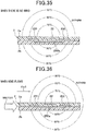
- the first and second connection patterns 231, 232 have no temperature difference therebetween, as shown in Fig. 35 , when there is no wind, similarly to the wind direction meter 1 of the aforementioned embodiment, and when the wind flows, the first and second connection patterns 231, 232 produce a temperature difference therebetween as shown in Fig. 36 . Therefore, an electromotive force is produced, and the direction of the wind can be measured.
- the movement direction meter 1A for measuring the movement direction of a moving body in the present embodiment.
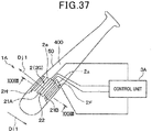
- the movement direction meter 1A is arranged in a moving body 50, and includes a plurality of sensors 2 and a control unit 3.
- examples of the moving body 50 include a baseball bat, a golf club, a tennis racket, a table tennis racket, movable parts of manufacturing equipment and arm robots, controllers for game machines, and the like. Description herein is provided by way of an example in which the moving body is a baseball bat 50.
- a plurality of sensors 2 are adhered onto a surface 400 of the bat 50.
- the sensor 2 of the present embodiment has the same structure as that of the sensor 2 of the first embodiment. As shown in Figs. 37 and 38 , each sensor 2 is fixed to the bat 50 so that a first thermoelectric conversion element 21A and a second thermoelectric conversion element 21B are positioned on both sides of a heater 22 in a direction parallel to the movement direction of the bat 50 (e.g., the direction of Dj1).
- the wiring electrically connecting the sensor 2 to the control unit 3 may better be arranged so as not to be obstructive such as by winding the wiring about the bat 50, or boring a hole into the bat 50 and passing the wiring through the hole for placement inside the bat 50.
- a movement of the bat 50 creates a situation similar to the situation where the wind flows in the direction opposite to the direction of the movement of the bat 50.
- a movement of the bat 50 creates a situation similar to the situation where the wind flows in the direction opposite to the direction of the movement in a resting bat 50.
- movement of the bat 50 in the direction of Dj1 creates a situation similar to the situation where the wind flows in a direction of Di1 which is opposite to the direction of Dj1.
- the movement direction of the bat 50 can be measured. Accordingly, the movement direction of the bat 50 can be measured based on the same concept as that of the method of measuring the direction of the wind using the wind direction meters 1 described in the first to third embodiments.
- the movement direction meter 1A of the present embodiment measures the wind generated relative to the bat 50 above the first surface 2a when the bat 50 is moved to thereby measure the movement direction of the bat 50.
- the movement direction meter 1A may include a plurality of sensors 2 (sensors 2A to 2H shown in the figure) so as to be able to measure the directions corresponding to a plurality of different directions (8 directions Dj1 to Dq1 herein) in which the bat 50 is likely to move.
- sensors 2G sensors 2G to 2H shown in the figure
- the direction of the wind which is produced relatively when the bat 50 is moved in the direction of the arrow Dj1 of Fig. 38 is in a direction parallel to the first surface 2a, but is not parallel to the first surface 2a for other sensors 2A to 2F and 2H.
- the movement direction meter 1A of the present embodiment specifies a sensor 2 that has generated an electromotive force with a positive polarity and with a maximum absolute value from among the plurality of sensors 2 to thereby specify the direction of the wind (the direction of Dj1 when the electromotive force of the sensor 2G is positive and maximum), and further measure the movement direction of the bat 50 (the direction of Di1 when the electromotive force of the sensor 2G is positive and maximum).
- the control unit 3A is the movement direction calculation unit for calculating the movement direction of a moving body, as an object to be measured, on the basis of the detection result of each sensor 2.
- the control unit 3A is an electronic control unit configured, for example, by a microcomputer, a memory as a storage section, and a peripheral circuit.
- the control unit 3A functions to control the activation and deactivation of the heater 22.
- the control unit 3A calculates the movement direction of the bat 50 on the basis of the difference in the value of electromotive force generated in each of the plurality of sensors 2.
- the position of the heater 22 may be changed in the sensor 2 of the first embodiment.
- the heater 22 has been positioned in the center part in a direction perpendicular to the first surface 2a and the second surface 2b of the sensor 2, but the heater 22 may be positioned on the first surface 2a of the sensor 2.
- the heater 22 may be configured by a resistor which generates heat with an application of current, and the resistor may be provided to the front surface protective member 24, being exposed therefrom.
- a windshield may be provided between the plurality of sensors 2 in the wind direction meters 1 of the first to third embodiments and the movement direction meter 1A of the fourth embodiment.
- the generation of a Karman vortex can be prevented on the leeward side of the sensor 2, and thus the direction of the wind or the movement direction of a moving body can be measured with a high accuracy.
- the wind direction meters 1 of the first to third embodiments measure the direction of the wind, as an object to be measured, on the basis of the difference in electromotive force generated in each of the plurality of sensors 2, and similarly, the movement direction of a moving body (the bat) 50 is measured on the basis of the difference in the value of electromotive force generated in each of the plurality of sensors 2 in the movement direction meter 1A of the fourth embodiment.
- the direction of the wind and the movement direction of the moving body 50 may be measured on the basis of the difference in current, instead of voltage, in the first to fourth embodiments.
- the wind direction meter 1 and the movement direction meter 1A of the present invention can calculate the direction of the wind and the movement direction of the moving body 50 on the basis of the difference in electrical output of either the voltage or the current generated in each of the plurality of sensors 2.
- the temperature difference and the volume of the wind there is a fixed relationship between the temperature difference and the volume of the wind, the temperature difference occurring at the first ends 21aa, 21ba, 250aa, 250ba and the second ends 21ab, 21bb, 250ab, 250bb of the first and second conductors (the first and second interlayer connection members 21a, 21b, P- and N-type elements 250a, 250b) in the wind direction meters 1 of the first to third embodiments.
- the value of electromotive force generated by the sensor 2 in conformity with the temperature difference and the volume of the wind.
- this relationship can be used for providing a wind direction/flow meter in which a flow meter is configured by the wind direction meter 1 of the first to third embodiments to measure the wind volume on the basis of the value of the electromotive force outputted from the sensor 2.
- the wind volume may be ensured to be calculated in the control units 3 of the first to third embodiments, on the basis of the value of the electromotive force outputted from the sensor 2 and the relationship of the value of the electromotive force with the wind volume.
- a sensor 2 having positive polarity and generating an electromotive force with a maximum absolute value is ensured to be specified from among the plurality of sensors 2, for calculation of the wind volume on the basis of the value of the electromotive force generated by the specified sensor 2.
- a sensor 2 having negative polarity and generating an electromotive force with a maximum absolute value is ensured to be specified from among the plurality of sensors 2, for consideration of the value of the electromotive force generated by the specified sensor 2.
- the relationship of the electromotive force outputted from the sensor 2 with the wind volume may be obtained in advance by experiments or the like and stored in the memory of the control unit 3 in advance.
- the wind direction meters 1 of the first to third embodiments have a configuration provided with eight sensors 2, but the number of sensors 2 is not limited to this.
- the wind direction meter 1 may have a configuration provided with three sensors 2.
- the number of sensors 2 is not limited to even numbers, but may be an odd number.
- the plurality of sensors 2 are disposed at even intervals on the circumference S1, but the plurality of sensors 2 do not have to be disposed at even intervals.
- the wind direction meters 1 of the first to third embodiments use eight sensors 2 to measure the wind in eight directions (8 azimuths), but the number of sensors 2 in the wind direction meter 1 and the number of wind directions measured by the wind direction meter 1 can be changed as desired.
- the control unit 3 calculates the wind direction on the basis of the outputs from the plurality of sensors 2 and the relationship of the outputs with the respective 8 azimuths. This can specify as to which of the 8 azimuths the wind direction in question corresponds to.
- the output of the plurality of sensors 2 arranged in the plane 5a each depend on the wind direction.
- the control unit 3 may be configured to calculate the wind direction on the basis of the outputs of the plurality of sensors 2, and the relationship of all the wind directions to be specified with the outputs of the plurality of sensors 2. This can specify as to which of the plurality of directions the wind direction desired to be specified corresponds to.
- the wind direction is calculated on the basis of the outputs of the plurality of sensors 2, and the relationship of the wind directions to 360 azimuths with the outputs of the plurality of sensors 2.
- This can specify as to which of the 360 azimuths the wind direction in question corresponds to. Namely, the wind in every direction can be specified.
- each sensor 2 is configured such that a thermoelectric conversion element 21A and a thermoelectric conversion element 21B are disposed to sandwich the heater 22, but other configurations may be used.
- each sensor 2 may be configured such that a thermoelectric conversion element 21A is disposed on one side of the heater 22 (upper side of the figure) and two thermoelectric conversion elements 21B1, 21B2 are disposed on the other side (lower side of the figure).
- two thermoelectric conversion elements 21A1, 21A2 may be disposed on one side of the heater 22, and a thermoelectric conversion element 21B may be disposed on the other side.
- thermoelectric conversion elements 21A1, 21A2 may be disposed on one side of the heater 22 and two thermoelectric conversion elements 21B1, 21B2 may be disposed on the other side.
- the number of thermoelectric conversion elements 21 disposed on one side and the other side of the heater 22 may be changed as desired.
- the number of thermoelectric conversion elements 21 disposed on one side and the other side of the Peltier element 320 may be changed as desired.
- a thermoelectric conversion element 21 referred to herein is configured so that the first interlayer connection member 21a and the second interlayer connection member 21b are serially connected.
- the two thermoelectric conversion elements 21A, 21B disposed sandwiching the heater 22 are in a rectangular shape, but they may be in other shapes.
- the two thermoelectric conversion elements 21A, 21B may each be in a trapezoidal shape as shown in Fig. 43 , a circular shape as shown in Fig. 44 , or a triangular shape as shown in Fig. 45 .
- the two thermoelectric conversion elements 21, 21B do not have to be in the same shape, but may be in different shapes as shown in Fig. 46 .
- the shape of the thermoelectric conversion element 21 refers to the shape of the region for forming the thermoelectric conversion element 21.
- the shape formed by the line is the shape of the region for forming the thermoelectric conversion element 21.
- the wind direction meter 1 of the second embodiment is the same applies to the wind direction meter 1 of the second embodiment.
Landscapes
- Physics & Mathematics (AREA)
- General Physics & Mathematics (AREA)
- Engineering & Computer Science (AREA)
- Aviation & Aerospace Engineering (AREA)
- Indicating Or Recording The Presence, Absence, Or Direction Of Movement (AREA)
- Measuring Volume Flow (AREA)
Abstract
Description
- The present invention relates to a wind direction meter, a wind direction/flow meter, and a movement direction meter.
- As a conventional wind direction meter, there is a vane-type wind direction meter which uses the same principles as a weathervane (e.g., refer to PTL1). The wind direction meter is provided with a rotary shaft supported by a bearing, and a vane (arrow feather) which receives the wind and is rotatable around the rotary shaft, and indicates the wind direction by the direction in which the vane is oriented.
- PTL1:
JP-A-H08-160065 - However, when measuring the wind direction, the aforementioned conventional wind direction meter generates friction in the mechanically movable parts constituted by the bearing and the rotary shaft. Thus, while the conventional wind direction meter can detect the wind direction of a comparatively high wind speed, there has been difficulty in detecting the wind direction of a weak wind such as an indoor airflow.
- Therefore, wind direction meters and wind direction/flow meters are desired to have the ability of detecting the direction of a weak wind. Similarly, movement direction meters, which use a wind direction meter for measuring the movement direction of an object to be moved, are also desired to have the ability of detecting the direction of a weak wind.
- In light of the circumstances set forth above, the present invention has an object to provide a wind direction meter, a wind direction/flow meter, and a movement direction meter, which are capable of detecting the direction of a weak wind.
- To achieve the aforementioned purpose, the wind direction meter of the subject matter recited in
claim 1 is a wind direction meter having a first surface (2a) and measuring a direction of a wind flowing above the first surface (2a), and has the following features. Specifically, the wind direction meter includes: a plurality of sensors (2) each formed with the first surface and provided with: a thermoelectric conversion element (21, 21A, 21B, 370) having a first conductor (21a, 250a) that has a first end (21aa, 250aa) and a second end (21ab, 250ab) opposite to the first end made of a metal or a semiconductor, and having a second conductor (21b, 250b) that has a first end (21ba, 250ba) and a second end (21bb, 250bb) opposite to the first end made of a metal or a semiconductor different from the first conductor, the first conductor and the second conductor being serially connected to each other, and the first ends (21aa, 21ba, 250aa, 250ba) being on a mutually connected side of the first conductor and the second conductor, and the second end (21ab, 250ab) of the first conductor, and the second end (21bb, 250bb) of the second conductor generating electrical outputs, when a temperature difference occurs; and a temperature changing unit (22, 320) for changing an ambient temperature by performing at least one of heat generation and heat absorption. In the wind direction meter, when the surrounding air, whose temperature has been changed by the temperature changing unit, is moved by the wind to cause a temperature difference between the first end and the second end of the respective first conductor and the second conductor, the outputs are ensured to be generated in conformity with the temperature difference, and the outputs, which are generated when the wind flows in a predetermined direction, have values different from each other; and a wind direction calculation unit (3) is provided for calculating a direction of the wind on the basis of a difference between the values of the outputs generated in each of the plurality of sensors. - With this configuration, since the wind direction is detected by using a thermoelectric conversion element which does not have mechanically movable parts, the wind direction of a weak wind can be detected.
- Further, a wind direction/flow meter of the subject matter recited in
claim 5 is a wind direction/flow meter which includes the wind direction meter according toclaim 1. In the wind direction/flow meter, the wind direction calculation unit also configures a flow meter for calculating a wind volume on the basis of the values of the outputs. Since this configuration, includes the wind direction meter recited inclaim 1, the wind direction of a weak wind can be detected. - Further, a movement direction meter of the subject matter recited in claim 6 has a first surface and arranged in a moving body (50) to measure a movement direction of the moving body by measuring a wind relatively generated to the moving body, the wind being generated above the first surface when the moving body moves, and has the following features. Specifically, the movement direction meter includes: a plurality of sensors (2) each formed with the first surface and provided with: a thermoelectric conversion element (21, 21A, 21B, 370) having a first conductor (21a, 250a) that has a first end (21aa, 250aa) and a second end (21ab, 250ab) opposite to the first end and is made of a metal or a semiconductor, and having a second conductor (21b, 250b) that has a first end (21ba, 250ba) and a second end (21bb, 250bb) opposite to the first end and is made of a metal or a semiconductor different from the first conductor, the first conductor and the second conductor being serially connected to each other, and the first ends (21aa, 21ba, 250aa, 250ba) on mutually connected side of the first conductor and the second conductor, and the second end (21ab, 250ab) of the first conductor, and the second end (21bb, 250bb) of the second conductor generating electrical outputs when a temperature difference occurs; and a temperature changing unit (22, 320) for changing an ambient temperature by performing at least one of heat generation and heat absorption. In the movement direction meter, when the surrounding air, whose temperature has been changed by the temperature changing unit, is moved by the wind to cause a temperature difference between the first end and the second end of the respective first conductor and the second conductor, the outputs are ensured to be generated in conformity with the temperature difference; and the outputs, which are generated when the wind flows in a predetermined direction, have values different from each other; and a movement direction calculation unit (3A) is provided for calculating a movement direction of the moving body on the basis of a difference between the values of the outputs generated in each of the plurality of sensors.
- With this configuration, the wind direction is detected by using a thermoelectric conversion element which does not have mechanically movable parts. Thus, when a moving body is moved, by measuring the wind generated relative to the moving body, the wind direction of the wind can be detected even when the wind is weak.
-
-
Fig. 1 is a perspective view illustrating a general configuration of awind direction meter 1, according to a first embodiment. -
Fig. 2 is a diagram illustrating a planar configuration of thewind direction meter 1 shown inFig. 1 . -
Fig. 3 is a diagram illustrating the movement of hot air generated by aheater 22 and corresponding toFig. 2 . -
Fig. 4 is a plan view of asensor 2 shown inFig. 1 . -
Fig. 5 is a cross-sectional view taken along the line V-V ofFig. 4 . -
Fig. 6 is a set of cross-sectional views illustrating steps of producing thesensor 2, according to the first embodiment. -
Fig. 7 is a diagram illustrating temperature distribution in the vicinity of thesensor 2 when there is no wind, according to the first embodiment. -
Fig. 8 is a diagram illustrating temperature distribution in the vicinity of thesensor 2 when wind flows, according to the first embodiment. -
Fig. 9 is a plan view of asensor 2, according to a second embodiment. -
Fig. 10 is a cross-sectional view taken along the line X-X ofFig. 9 . -
Fig. 11 is a schematic diagram illustrating temperature distribution in the vicinity of thesensor 2 when there is no wind, according to the second embodiment and corresponding to the cross-section taken along the line XI-XI ofFig. 9 . -
Fig. 12 is a diagram illustrating temperature distribution in the vicinity of thesensor 2 when wind flows, according to the second embodiment and corresponding to the cross-section taken along the line XII-XII ofFig. 9 . -
Fig. 13 is a diagram illustrating temperature distribution in the vicinity of asensor 2 when wind flows, according to Comparative Example 1. -
Fig. 14 is a diagram illustrating a planar configuration of awind direction meter 1, according to a third embodiment. -
Fig. 15 is a plan view of thesensor 2 shown inFig. 14 . -
Fig. 16 is a bottom view of thesensor 2 shown inFig. 14 . -
Fig. 17 is a cross-sectional view taken along the line XVII-XVII ofFig. 15 . -
Fig. 18 is a cross-sectional view illustrating steps of producing thesensor 2, according to the third embodiment and corresponding toFig. 17 . -
Fig. 19 is a cross-sectional view taken along line XIX-XIX ofFig. 15 . -
Fig. 20 is a cross-sectional view illustrating steps of producing thesensor 2, according to the third embodiment and corresponding toFig. 17 . -
Fig. 21 is a diagram illustrating temperature distribution in the vicinity of thesensor 2 when there is no wind, according to the third embodiment. -
Fig. 22 is a diagram illustrating temperature distribution in the vicinity of thesensor 2 when wind flows, according to the third embodiment. -
Fig. 23 is a plan view illustrating asensor 2, according toModification 1 of the third embodiment. -
Fig. 24 is a bottom view illustrating thesensor 2 shown inFig. 23 . -
Fig. 25 is a cross-sectional view taken along line XXV-XXV ofFig. 23 . -
Fig. 26 is a cross-sectional view illustrating steps of producing thesensor 2, according toModification 1 of the third embodiment and corresponding toFig. 25 . -
Fig. 27 is a cross-sectional view taken along the line XXVII-XXVII ofFig. 23 . -
Fig. 28 is a cross-sectional view illustrating steps of producing thesensor 2, according toModification 1 of the third embodiment and corresponding toFig. 17 . -
Fig. 29 is a plan view illustrating asensor 2, according toModification 2 of the third embodiment. -
Fig. 30 is a bottom view illustrating thesensor 2 shown inFig. 29 . -
Fig. 31 is a cross-sectional view taken along the line XXXI-XXXI ofFig. 29 . -
Fig. 32 is a cross-sectional view illustrating steps of producing thesensor 2, according toModification 2 of the third embodiment and corresponding toFig. 31 . -
Fig. 33 is a cross-sectional view taken along the line XXXIII-XXXIII ofFig. 29 . -
Fig. 34 is a cross-sectional view illustrating steps of producing thesensor 2, according toModification 2 of the third embodiment and corresponding toFig. 33 . -
Fig. 35 is a diagram illustrating temperature distribution in the vicinity of thesensor 2 when there is no wind, according toModification 2 of the third embodiment. -
Fig. 36 is a diagram illustrating temperature distribution in the vicinity of thesensor 2 when wind flows, according toModification 2 of the third embodiment. -
Fig. 37 is a diagram illustrating a general configuration of amovement direction meter 1A (including a bat 50), according to a fourth embodiment. -
Fig. 38 is a cross-sectional view taken along the line XXXVIII-XXXVIII ofFig. 37 . -
Fig. 39 is a plan view illustrating awind direction meter 1, according to another embodiment. -
Fig. 40 is a plan view illustrating asensor 2, according to another embodiment. -
Fig. 41 is a plan view illustrating asensor 2, according to another embodiment. -
Fig. 42 is a plan view illustrating asensor 2, according to another embodiment. -
Fig. 43 is a plan view illustrating asensor 2, according to another embodiment. -
Fig. 44 is a plan view illustrating asensor 2, according to another embodiment. -
Fig. 45 is a plan view illustrating asensor 2, according to another embodiment. -
Fig. 46 is a plan view illustrating asensor 2, according to another embodiment. - With reference to the drawings, hereinafter will be described some embodiments of the present invention. It should be noted that, in each of the following embodiments, portions that are the same as or equivalent to each other are given the same reference signs in the drawings.
- With reference to
Figs. 1 to 8 , awind direction meter 1 according to a first embodiment of the present invention will be described. Thewind direction meter 1 is a device which has afirst surface 2a, measures the direction of the wind flowing above thefirst surface 2a, and, as shown inFig. 1 , has a plurality ofsensors 2, acontrol unit 3, and adisplay unit 4. As an example, thewind direction meter 1 is configured to have eightsensors 2. - As shown in
Figs. 1 to 5 , the plurality ofsensors 2 are each configured by a sheet-like multilayer substrate having thefirst surface 2a and asecond surface 2b opposite to thefirst surface 2a. As shown inFigs. 1 and2 , the plurality ofsensors 2 are each provided to aplane 5a of a fixingmember 5, with thesecond surface 2b being adhered to theplane 5a of the fixingmember 5. Specifically, in the present embodiment, the entirety of eachsecond surface 2b of thesensor 2 is covered with the fixingmember 5. Further, the plurality ofsensors 2 are disposed in a manner of being offset from each other in the rotation direction centered on an axis perpendicular to theplane 5a. The plurality ofsensors 2 are disposed at different positions on the circumference (refer to the dashed line S1 inFig. 2 ) centered on the axis perpendicular to theplane 5a. Specifically, eightsensors 2 are disposed at even intervals on a circumference S1. Although this will be described in detail below, as shown inFig. 2 , thewind direction meter 1 according to the present embodiment can calculate the direction of the wind in 16 directions (refer to the arrows Da1, Da2, Db1, ..., Dh2 ofFig. 2 ) in the radial direction of the circle having the circumference S1. The 16 directions include directions substantially coinciding with each other (e.g., the arrows Da1 and De2 ofFig. 2 coincide with each other). Thus, the directions of the wind which can be measured in thewind direction meter 1 of the present embodiment are substantively eight directions. - As shown in
Figs. 4 and 5 , the plurality ofsensors 2 are each configured by two thermoelectric conversion elements 21 (a firstthermoelectric conversion element 21A and a secondthermoelectric conversion element 21B) and aheater 22. The twothermoelectric conversion elements 21 are disposed being interposed by theheater 22 therebetween, and are serially connected via wiring (backsurface patterns 29 described later). As an example herein, as shown inFig. 5 , the twothermoelectric conversion elements 21 and theheater 22 are disposed in the order of the firstthermoelectric conversion element 21A, theheater 22, and the secondthermoelectric conversion element 21B in a direction parallel to thefirst surface 2a and thesecond surface 2b of thesensor 2. Thesensor 2 is arranged in theplane 5a of the fixingmember 5 so that the first and secondthermoelectric conversion elements heater 22 in a direction parallel to the flow direction (refer to the arrows Da1, Da2 ofFig. 5 ) of the wind as an object to be detected. - Specifically, as shown in
Fig. 5 , thesensor 2 is configured by a multilayer substrate which is an integration of an insulatingbase material 23, a front surfaceprotective member 24 having thefirst surface 2a, and a back surfaceprotective member 25. Thethermoelectric conversion elements 21 and theheater 22 are arranged inside the multilayer substrate. - As shown in
Fig. 5 , eachthermoelectric conversion element 21 has a firstinterlayer connection member 21a and a secondinterlayer connection member 21b, and generates an electromotive force, i.e., a voltage, according to the temperature difference between both ends 21aa, 21ba, 21ab, 21bb of the respective first and secondinterlayer connection members interlayer connection members front surface patterns 28 described later), and are electrically connected to thecontrol unit 3. The firstinterlayer connection member 21a is made of a metal or semiconductor, and the secondinterlayer connection member 21b is made of a different metal or semiconductor than the firstinterlayer connection member 21a. The firstinterlayer connection member 21a corresponds to the first conductor in the claims, and the secondinterlayer connection member 21b corresponds to the second conductor in the claims. - As shown in
Fig. 5 , in thesensor 2 of the present embodiment, first ends 21aa, 21ba connected to each other on one side of the first and secondinterlayer connection members interlayer connection member 21a and a second end 21bb opposite to the first end 21ba of the secondinterlayer connection member 21b. More specifically, the first ends 21aa, 21ba are disposed so as to be respectively opposed to and in alignment with the second ends 21ab, 21bb in a direction perpendicular to the directions Da1, Da2 in which the wind flows. Further, in the present embodiment, the first ends 21aa, 21ba are disposed on thefirst surface 2a side of thesensor 2, and the second ends 21ab, 21bb are disposed on thesecond surface 2b side of thesensor 2. - Further, as shown in
Fig. 5 , in the present embodiment, a plurality (two) of thethermoelectric conversion elements 21 are connected in series via wiring (backsurface pattern 29 described later) in each of the plurality ofsensors 2. Thus, in the present embodiment, the electromotive force of thesensor 2 can be intensified, and thus high sensitivity can be imparted to thesensor 2. - The
heater 22 is a heat source for generating heat, and is configured by a heating wire, such as a nichrome wire, which generates heat when current is applied. Theheater 22 is provided as a temperature changing unit for changing ambient temperature by generating heat. Theheater 22 is electrically connected to thecontrol unit 3. In place of theheater 22, a cooler which changes the ambient temperature by absorbing heat may be used as the temperature changing unit for changing ambient temperature. - In the present embodiment, the insulating
base material 23 is made of a thermoplastic resin film, which is rectangular in plan view, typified such as by a polyether ether ketone (PEEK), polyetherimide (PEI), or liquid crystal polymer (LCP). - First and second via
holes first surface 2a to thesecond surface 2b, but may have a tapered shape with the diameter becoming smaller from thefirst surface 2a towards thesecond surface 2b. Further, the first and second viaholes second surface 2b towards thefirst surface 2a, or may be formed in a rectangular tube. - The first
interlayer connection member 21a is disposed in the first viahole 26, and the secondinterlayer connection member 21b is disposed in the second viahole 27. That is, the first and secondinterlayer connection members base material 23. - Since the first and second
interlayer connection members holes interlayer connection members holes sensor 2 can be increased in this way, and a high sensitivity is imparted to thesensor 2. - The first and second
interlayer connection members interlayer connection member 21a is made of a solid phase sintered metal compound in order to maintain a crystal structure of a plurality of metal atoms forming P-type Bi-Sb-Te alloy powder prior to sintering. Further, the secondlayer connection member 21b is made of a solid phase sintered metal compound in order to maintain a crystal structure of a plurality of metal atoms forming N-type Bi-Te alloy powder prior to sintering. Thus, the metal for forming each of the first and secondinterlayer connection members interlayer connection members sensor 2. - As described above, the
wind direction meter 1 according to the present embodiment uses the highlysensitive sensor 2. Accordingly, use of thesensor 2 enables detection of the direction of a weak wind flowing above thefirst surface 2a. - As shown in
Fig. 5 , thefront surface 23a of the insulatingbase materials 23 is arranged with the front surfaceprotective member 24 formed of a thermoplastic resin film, which is rectangular in plan view, typified such as by a polyether ether ketone (PEEK), polyetherimide (PEI), and liquid crystal polymer (LCP). The front surfaceprotective member 24 is ensured to have the same shape in plan view as that of the insulatingbase material 23. The front surfaceprotective member 24 has asurface 24a opposing the insulatingbase material 23 and formed with a plurality offront surface patterns 28 obtained by patterning a copper foil, etc. so as to be spaced apart from each other. Thefront surface patterns 28 are appropriately electrically connected to the respective first and secondinterlayer connection members - Specifically, as shown in
Fig. 5 , when apair 21c is formed by a firstinterlayer connection member 21a and a secondinterlayer connection member 21b that are adjacent to each other, the first and secondinterlayer connection members pair 21c are connected to the same singlefront surface pattern 28. In short, the first and secondinterlayer connection members pair 21c are electrically connected to each other via thefront surface pattern 28. In the present embodiment, thepair 21c is formed by a firstinterlayer connection member 21a and a secondinterlayer connection member 21b that are adjacent to each other along the longitudinal direction (the left-right direction inFig. 4 ) of the insulatingbase material 23. - The insulating
base material 23 has aback surface 23b which is opposite to thefront surface 23a. Theback surface 23b is arranged with the back surfaceprotective member 25 which is rectangular in plan view and formed of a thermoplastic resin film such as of polyether ether ketone (PEEK), polyetherimide (PEI), and liquid crystal polymer (LCP). The back surfaceprotective member 25 has a length in the longitudinal direction of the insulatingbase material 23 longer than the insulatingbase material 23, and is disposed on theback surface 23b of the insulatingbase material 23 so that both end parts in the longitudinal direction project from the insulatingbase material 23. - The back surface
protective member 25 has afirst surface 25a opposing the insulatingbase material 23 and formed with a plurality ofback surface patterns 29 obtained by patterning a copper foil, etc. so as to be spaced apart from each other. Each of theback surface patterns 29 is appropriately electrically connected to the corresponding first and secondinterlayer connection members - Specifically, as shown in
Fig. 5 , in the twopairs 21c that are adjacent to each other, the firstinterlayer connection member 21a of one of thepairs 21c and the secondinterlayer connection member 21b of theother pair 21c are connected to the same singleback surface pattern 29. In short, bridging thepairs 21c, the first and secondinterlayer connection members back surface pattern 29. - In this way, the
pairs 21c are serially connected as shown by the dashed line inFig. 4 . The dashed line inFig. 4 shows a plurality of serially connectedpairs 21c and the wiring. - In the
heater 22 of eachsensor 2, aheating wire 22a is buried inside the insulatingbase material 23. Theback surface pattern 29 is formed under theheater 22 of thesensor 2 so as to straddle theheater 22. The first and secondinterlayer connection members thermoelectric conversion element 21A are serially connected to the first and secondinterlayer connection members thermoelectric conversion element 21B via theback surface patterns 29. - As shown in
Fig. 5 , of theback surface patterns 29 in eachsensor 2 of the present embodiment, those which correspond to the end portions of the serial connection described above are formed being exposed from the insulatingbase material 23. An end portion exposed from the insulatingbase material 23 among theback surface patterns 29 serves as a terminal connected to thecontrol unit 3. - As shown in
Fig. 5 , in eachsensor 2 of the present embodiment, the structures of the two thermoelectric conversion elements 21 (the first and secondinterlayer connection members front surface patterns 28, and the back surface patterns 29) are linearly symmetric with respect to theheater 22 provided as an axis between the twothermoelectric conversion elements 21. Namely, the first and secondthermoelectric conversion elements heater 22. Further, between the first and secondthermoelectric conversion elements interlayer connection members thermoelectric conversion elements interlayer connection members interlayer connection members thermoelectric conversion elements 21, the twothermoelectric conversion elements 21 generate electromotive forces having different polarities (e.g., one is positive and the other is negative). Further, if the first ends 21aa, 21ba of the first and secondinterlayer connection members thermoelectric conversion elements 21 as well, the twothermoelectric conversion elements 21 generate electromotive forces having different polarities. Further, if the first ends 21aa, 21ba have a higher temperature than the second ends 21ab, 21bb in the firstthermoelectric conversion element 21A, and the first ends 21aa, 21ba have a lower temperature than the second ends 21ab, 21bb in the secondthermoelectric conversion element 21B, the twothermoelectric conversion elements 21 generate electromotive forces having the same polarity. Thus, in thesensor 2, electromotive forces of the same polarity are generated when a reverse relationship is established between the first and secondthermoelectric conversion elements - The configuration of the
sensor 2 of the present embodiment is as described above. In each of the regions of the first and secondthermoelectric conversion elements sensor 2, the first ends 21aa, 21ba of the first and secondinterlayer connection members first surface 2a side, and the second ends 21ab, 21bb thereof are arranged on thesecond surface 2b side. Therefore, if the temperature on thefirst surface 2a side is different from the temperature on thesecond surface 2b side in thesensors 2, the temperature at the first ends 21aa, 21ba of the first and secondinterlayer connection members sensor 2, the temperature difference leads to generation of an electromotive force, the degree of which depends on the degree of difference in the temperature. Thewind direction meter 1 of the present embodiment outputs the electromotive force as a sensor signal to thecontrol unit 3. The electromotive force is changed when the aforementioned temperature difference is changed. - With reference to
Fig. 6 , a method of manufacturing thesensor 2 of the present embodiment will be described. - The method uses the insulating
base material 23 as shown inFig. 6(a) . The insulatingbase material 23 is formed as follows. The insulatingbase material 23 to be used herein is embedded with aheater 22. A plurality of the first viaholes 26 are formed in the insulatingbase material 23 by means of a drill, a laser, or the like. Next, the first viaholes 26 are filled with a firstconductive paste 21d. The method (device) of filling the first viaholes 26 with the firstconductive paste 21d may be the method (device) described in Japanese Patent Application No.2010-50356 - When the method is briefly described, although not shown, the insulating
base material 23 is arranged on a holding table, via absorption paper, so that theback surface 23b is opposed to the absorption paper. Then, the firstconductive paste 21d, while being melted, is filled in the first via holes 26. Thus, most of the organic solvent in the firstconductive paste 21d is adsorbed by the absorption paper, and the alloy powder is arranged being in intimate contact with the first viahole 26. - The absorption paper only has to be a material capable of adsorbing the organic solvent in the first
conductive paste 21d, and may be generally used high quality paper. The firstconductive paste 21d is a paste material obtained by adding an organic solvent, such as paraffin, having a melting point of 43°C, to a Bi-Sb-Te alloy powder in which the metal atoms maintain a predetermined crystal structure. Therefore, the firstconductive paste 21d is filled in a state where thefront surface 23a of the insulatingbase material 23 is heated to approximately 43°C. - Subsequently, a plurality of the second via
holes 27 are formed in the insulatingbase material 23 by means of a drill, laser, and the like. - Next, a second
conductive paste 21e is filled in the second via holes 27. This process can be performed similarly to the process of filling the firstconductive paste 21d. Namely, although not shown, after arranging the insulatingbase material 23 on the holding table, via the absorption paper, so that theback surface 23b is opposed to the absorption paper, the secondconductive paste 21e is filled in the second via holes 27. Thus, most of the organic solvent in the secondconductive paste 21e is adsorbed by the absorption paper, and the alloy powder is arranged being in intimate contact with the second via holes 27. - The second
conductive paste 21e is a pasted material obtained by adding an organic solvent, such as terpineol, having a melting point of room temperature, to a Bi-Te alloy powder in which the metal atoms different from those constituting the firstconductive paste 21d maintain a predetermined crystal structure. In other words, the organic solvent constituting the secondconductive paste 21e is one having a melting point lower than that of the organic solvent constituting the firstconductive paste 21d. The secondconductive paste 21e is filled in a state where thefront surface 23a of the insulatingbase material 23 is maintained at room temperature. In other words, the filling of the secondconductive paste 21e is performed in a state where the organic solvent contained in the firstconductive paste 21d is solidified. Thus, the secondconductive paste 21e is prevented from mixing into the first via holes 26. - The state where the organic solvent contained in the first
conductive paste 21d is solidified refers to the state where the organic solvent remains in the first viahole 26 without being adsorbed by the absorption paper in the process of filling the firstconductive paste 21d. - The method also uses the front surface
protective member 24 and the back surfaceprotective member 25 shown in (b) and (c) ofFig. 6 . These members are formed as follows. First, a copper foil, etc., is formed on each of thefirst surfaces protective member 24 and the back surfaceprotective member 25, respectively, facing the insulatingbase material 23. Then, by appropriately patterning the copper foils, a plurality offront surface patterns 28 spaced apart from each other and a plurality ofback surface patterns 29 spaced apart from each other are formed on the front surfaceprotective member 24 and the back surfaceprotective member 25, respectively. - Then, as shown in
Fig. 6(d) , the back surfaceprotective member 25, the insulatingbase material 23, and the front surfaceprotective member 24 are laminated in this order to form alaminate 215. The laminate 215 is placed between a pair of press plates, not shown, followed by heating and pressing the laminate in a vacuum state from above and below in the lamination direction, thereby integrating the laminate. Specifically, the first and the secondconductive pastes interlayer connection members interlayer connection members front surface patterns 28 and theback surface patterns 29, respectively, to thereby integrate thelaminate 215. - Although not specifically limited, when integrating the laminate 215, a cushioning material such as rock wool paper may be arranged between the laminate 215 and each of the press plates. The
sensor 2 is produced as described above. - Further, as shown in
Fig. 1 , thecontrol unit 3 is the wind direction calculation unit for calculating the direction of the wind which is an object to be measured on the basis of a detection result of thesensors 2. Thecontrol unit 3 is an electronic control unit configured by a microcomputer, a memory as a storage section, and a peripheral circuit thereof, and performs a predetermined arithmetic processing according to a given program to control the operation of thedisplay unit 4. Further, thecontrol unit 3 functions as a unit for controlling the activation and deactivation of theheaters 22. - The
display unit 4, such a monitor, displays the wind direction calculated by thecontrol unit 3. - The fixing
member 5 having aplane 5a serves as a member for fixing the plurality ofsensors 2 in theplane 5a. The fixingmember 5 of the present embodiment is formed of a material which transfers less heat than the air above thefirst surface 2a (or, the wind flowing above thefirst surface 2a) or the material for forming thesensor 2, and thus is formed of resin, for example. - Referring now to
Figs. 7 and 8 , the method of measuring the wind direction using thewind direction meter 1 of the present embodiment will be described. - When measuring the wind direction with the
wind direction meter 1 of the present embodiment, theheaters 22 in the plurality of (eight)sensors 2 are activated to generate heat. - Initially, operation in a
sensor 2 will be described. - First, the case when the wind, as an object to be measured, in the sensor 2 (the wind flowing above the
first surface 2a) does not flow (hereinafter, referred to as when there is no wind) will be described. As shown inFig. 7 , when there is no wind, the heat of theheater 22 is transmitted to form the temperature distribution shown by the isotherm ofFig. 7 in the air (or the wind) on thefirst surface 2a side of thesensor 2, while forming a temperature distribution shown by the isotherm ofFig. 7 in the fixingmember 5 on thesecond surface 2b side of thesensor 2. Thefirst surface 2a side of thesensor 2 reaches a temperature in conformity with the temperature distribution of the air (wind) above thefirst surface 2a, and thesecond surface 2b side of thesensor 2 reaches a temperature in conformity with the temperature distribution of the fixingmember 5. Specifically, a temperature distribution is formed on thefirst surface 2a side and thesecond surface 2b of thesensor 2 side, in which an area closer to theheater 22 has a higher temperature. In thesensor 2 of the present embodiment, as stated above, the structures of the twothermoelectric conversion elements 21 are linearly symmetric with respect to theheater 22 as an axis. Therefore, as shown in the isotherm ofFig. 7 , thesensor 2 of the present embodiment transmits the heat generated from theheater 22, when there is no wind, equally to both sides (two thermoelectric conversion elements 21) sandwiching theheater 22. Specifically, compared to the temperature generated when the distances from theheater 22 on the first andsecond surfaces sensor 2 are the same, the temperature on thefirst surface 2a side where the wind passes becomes higher than the temperature on thesecond surface 2b side provided with the fixingmember 5. As a result, the two corresponding firstinterlayer connection members 21a sandwiching theheater 22 and disposed in symmetric positions have equivalent temperature differences between both ends (the first end 21aa and the second end 21ab ofFig. 5 ). Similarly, the two corresponding secondinterlayer connection members 21b sandwiching theheater 22 and disposed in symmetric positions have equivalent temperature differences between both ends (the first end 21aa and the second end 21ab ofFig. 5 ). Furthermore, thesensor 2 of the present embodiment is configured, as stated above, such that a reverse relationship is established in respect of the level of temperature and the polarity of electromotive force. Therefore, in thesensor 2 of the present embodiment, when there is no wind, the respective electromotive forces generated by the twothermoelectric conversion elements 21 are of equivalent magnitude and the polarities thereof are the reverse of each other. Thus, the entire electromotive force of the respective plurality ofsensors 2 becomes zero. Similarly, the electromotive force of the plurality ofsensors 2 becomes zero when there is no wind. Since the present embodiment is provided with the fixingmember 5 configured by a material which hardly transfers heat, the interval of each isotherm is smaller, as shown inFig. 7 , in the temperature distribution on thesecond surface 2b side of thesensor 2 than the temperature distribution on thefirst surface 2a side. - The case when the wind (the wind flowing above the
first surface 2a), as an object to be measured, flows to thesensor 2 will be described by way of an example in which the wind flows in the direction of the arrow Da1 to asensor 2A shown inFig. 2 . As shown inFig. 8 , when the wind as an object to be measured flows, the temperature distribution shown by the isotherm ofFig. 8 is formed in the air (or the wind) on thefirst surface 2a side of thesensor 2, and the temperature distribution shown by the isotherm ofFig. 8 is formed in the fixingmember 5 on thesecond surface 2b side of thesensor 2. In the present embodiment, when the wind flows above thefirst surface 2a, the air (hereinafter, referred to as hot air) on thefirst surface 2a side in the surrounding air whose temperature has been changed by theheater 22 is moved in the direction (right direction ofFig. 8 ) parallel to thefirst surface 2a by the wind. In this case, in the present embodiment, the entirety of thesecond surface 2b of thesensor 2 is covered with the fixingmember 5 as mentioned above, and thus the wind does not flow to thesecond surface 2b side of thesensor 2. Therefore, thesecond surface 2b side air of the hot air is not moved by the wind (or, is moved slowly compared to the air on thefirst surface 2a side). Therefore, as shown inFig. 8 , when the wind flows over thewind direction meter 1 of the present embodiment, the temperature distribution is changed in the air (or the wind) on thefirst surface 2a side of thesensor 2. - As a result, immediately after flow of the wind over the
sensor 2, thefirst surface 2a side in thethermoelectric conversion element 21 on the right side ofFig. 8 will have a high temperature as shown inFig. 8 , and further, the respective first ends 21aa, 21ba of the first and secondinterlayer connection members first surface 2a side in thethermoelectric conversion element 21 on the left side ofFig. 8 will have a low temperature, and further, the respective first ends 21aa, 21ba of the first and secondinterlayer connection members second surface 2b side is not moved by the wind. Thus, the temperature will not change in the respective second ends 21ab, 21bb of the first and secondinterlayer connection members thermoelectric conversion elements 21 ofFig. 8 . Therefore, in the twothermoelectric conversion elements 21, temperature difference is caused between both ends 21aa, 21ba and 21ab, 21bb of the first and secondinterlayer connection members thermoelectric conversion elements thermoelectric conversion elements 21, temperature difference is caused between the first ends 21aa, 21ba of the first and secondinterlayer connection members interlayer connection member 21a and the second end 21bb of the secondinterlayer connection member 21b. Thus, thesensor 2 generates a positive electromotive force in conformity with the temperature difference between both ends 21aa, 21ba and 21ab, 21bb. In addition, since the two serially connectedthermoelectric conversion elements 21 produce electromotive forces having the same polarity (positive), compared to the case when there is onethermoelectric conversion element 21, the electromotive force of thesensor 2 is intensified, and a high sensitivity can be imparted to thesensor 2. When the wind flows in the direction (arrow Da2 ofFig. 2 ) opposite to Da1, thesensor 2 generates a negative electromotive force having an absolute value equivalent to that of the electromotive force generated when the wind flows in the direction ofDa 1. - In the present embodiment, each
sensor 2 operates as described above. Next, a method of measuring the wind direction using the plurality of (eight)sensors 2 operating in this way will be described. - As stated above, the plurality of
sensors 2 are disposed being offset from each other in the rotation direction centered on a line perpendicular to theplane 5a. Therefore, in the present embodiment, the plurality ofsensors 2 generate electromotive forces of different values when the wind flows in a predetermined direction. Specifically, among the plurality ofsensors 2, thesensor 2 above which the hot air has been moved by the wind over a wide range of thefirst surface 2a (the first ends 21aa, 21ba of the first and secondinterlayer connection members Fig. 3 , in the case when the direction of the wind is the direction of the arrow Da1 ofFig. 2 , the hot air is transmitted over a wide range of thefirst surface 2a of thesensor 2A, and thus the absolute value of the electromotive force to be generated increases. Further, in this case, the hot air is transmitted over a narrower range in thesensor 2B compared to thesensor 2A, and thus the electromotive force to be generated decreases. Further, the hot air is transmitted over a further narrower range in thesensor 2C, and thus the electromotive force to be generated further decreases. Furthermore, the range over which the hot air that has been moved by the wind is transmitted to thefirst surface 2a depends upon to what extent the direction of the wind agrees with the direction of the row of the firstthermoelectric conversion element 21A, theheater 22, the second andthermoelectric conversion element 21B for the respective sensors. Considering what has been described above, for example, by specifying thesensor 2 among the plurality ofsensors 2, which has generated an electromotive force with positive polarity and with a maximum absolute value, the direction of the wind (the direction of Da1 when the electromotive force of thesensor 2A is positive and the maximum) can be measured. - When the wind flows in the opposite direction (in the direction of Da2 opposite of Da1 herein), the electromotive force of the
sensor 2 becomes negative. This design may be used to ensure onesensor 2 can measure the two directions (Da1 and Da2) opposite to each other. In this case, for example, in thewind direction meter 1 of the present embodiment, thesensors sensors - In this way, the
wind direction meter 1 of the present embodiment measures the direction of the wind, as an object to be measured, on the basis of the difference in the electromotive force generated in each of the plurality ofsensors 2. - As described above, the
wind direction meter 1 of the present embodiment detects the wind direction using thesensor 2 having no mechanically movable parts, enabling detection of a weak wind. Coupled with this configuration, use of thesensor 2 having a high sensitivity in thewind direction meter 1 of the present embodiment specifically enables detection of the direction of a weak wind. - Since the conventional wind direction meters as mentioned above have mechanically movable parts, the vane unavoidably rotates due to inertia when the wind direction changes. Therefore, there has been a problem that the wind direction has to be calculated waiting until cease of the rotation of the vane due to inertia, or taking account of the rotation due to the inertia. In this regard, such a problem is not raised with the
wind direction meter 1 of the present embodiment using thesensor 2 having no mechanically movable parts. - An error with regards to the temperature difference between the first and
second surfaces sensor 2 of the present embodiment is configured, as stated above, such that a reverse relationship is established in respect of the level of temperature and the polarity of electromotive force between the first ends 21aa, 21ba and the second ends 21ab, 21bb of the respective first and secondinterlayer connection members thermoelectric conversion elements 21 are of equivalent magnitude and the polarities thereof are reverse to each other. As a result, the entire electromotive force of the respective plurality ofsensors 2 becomes zero. Therefore, thesensor 2 of the present embodiment does not have an adverse effect (has only a small effect) on the value of the electromotive force generated by thesensor 2 if the aforementioned error occurs due to a change of the ambient environmental temperature, for example. - As described above, the
wind direction meter 1 of the present embodiment has thefirst surface 2a and measures the direction of the wind flowing above thefirst surface 2a, and is characterized by the employment of the following plurality ofsensors 2 and thecontrol unit 3. Namely, thesensor 2 is formed with thefirst surface 2a, and includes the firstinterlayer connection member 21a made of a metal or semiconductor, and a secondinterlayer connection member 21b made of a different metal or semiconductor than the firstinterlayer connection member 21a. Further, thesensor 2 is provided with athermoelectric conversion element 21 for generating an electromotive force when a temperature difference occurs between the first ends 21aa, 21ba and the second ends 21ab, 21bb of the respective first and secondinterlayer connection members sensor 2 generates an electromotive force, when the surrounding air whose temperature has been changed by theheater 22 is moved by the wind to cause a temperature difference between the first ends 21aa, 21ba and the second ends 21ab, 21bb of the first and secondinterlayer connection members control unit 3 calculates the direction of the wind, as an object to be measured, on the basis of the difference in electromotive force generated in each of the plurality ofsensors 2. - In this way, since the
wind direction meter 1 of the present embodiment uses thethermoelectric conversion element 21 having no mechanically movable parts to detect the wind direction, the direction of a weak wind can be detected. Coupled with this configuration, use of thesensor 2 having a high sensitivity in thewind direction meter 1 of the present embodiment specifically enables detection of the direction of a weak wind. - In the
wind direction meter 1 of the present embodiment, thesensor 2 is configured such that the twothermoelectric conversion elements 21 are disposed sandwiching theheater 22, while being serially connected to each other via wiring (back surface pattern 29). Furthermore, thesensor 2 is configured such that a reverse relationship is established in respect of the level of temperature and the polarity of electromotive force between the first ends 21aa, 21ba and the second ends 21ab, 21bb of the respective first and secondinterlayer connection members - Therefore, the
wind direction meter 1 of the present embodiment can increase the electromotive force generated by thesensor 2 and impart a high sensitivity to thesensor 2, compared to the case where thethermoelectric conversion element 21 is disposed on only one side of theheater 22. - In the aforementioned
wind direction meter 1 of the present embodiment, thesensor 2 is provided with the two thermoelectric conversion elements 21 (the first and secondthermoelectric conversion elements heater 22. However, in thewind direction meter 1 of the present embodiment, thesensor 2 may be provided with only one of the twothermoelectric conversion elements 21. With this configuration as well, when the wind as an object to be measured flows, the air on thefirst surface 2a side in the hot air is moved by the wind in a direction parallel to thefirst surface 2a, but the air on thefirst surface 2b side in the hot air is not moved by the wind. Therefore, an electromotive force is generated in conformity with the temperature difference which is due to the temperature difference between the first ends 21aa, 21ba and the second ends 21ab, 21bb of the respective first and secondinterlayer connection members - Further, in the aforementioned
wind direction meter 1 of the present embodiment, thesensor 2 is configured such that the twothermoelectric conversion elements 21 are disposed sandwiching theheater 22, while being serially connecting to each other via wiring (back surface pattern 29). However, in thewind direction meter 1 of the present embodiment, thesensor 2 may be configured such that the twothermoelectric conversion elements 21 are independently electrically connected to thecontrol unit 3. However, in this case, wiring for establishing connection with thecontrol unit 3 must be provided for each of the twothermoelectric conversion elements 21. Thus, it is preferable that thesensor 2 has the aforementioned configuration (the configuration in which twothermoelectric conversion elements 21 are serially connected). - Referring to
Figs. 9 to 13 , a second embodiment of the present invention will be described. In the second embodiment, theheater 22 of the first embodiment has been changed to aPeltier element 320. Since the rest of the configuration is similar to the first embodiment, description is omitted herein. - The
wind direction meter 1 of the first embodiment is configured to include theheater 22 as the temperature changing unit, but thewind direction meter 1 according to the present embodiment is configured to include, as shown inFigs. 9 and10 , aPeltier element 320 as the temperature changing unit. - Further, the
wind direction meter 1 of the first embodiment is configured by covering the entirety of thesecond surface 2b of thesensor 2 with the fixingmember 5 so that the wind does not flow to thesecond surface 2b side of thesensor 2. The present embodiment however is configured such that the wind can flow to thesecond surface 2b side of the sensor 2 (not only thefirst surface 2a). Specifically, although not shown, it is so configured, as an example, that a spacer is provided between each of the plurality ofsensors 2 and the fixingmember 5, and only a part of thesecond surface 2b is covered by the spacer in each of the plurality ofsensors 2. - The
Peltier element 320 is a heat source which generates both heat and cold. As shown inFig. 9 , thePeltier element 320 is formed on a multilayer substrate together with the first and secondthermoelectric conversion elements sensors 2. In the present embodiment, thePeltier element 320 has a structure similar to that of the firstthermoelectric conversion element 21A. Namely, thePeltier element 320 includes a firstinterlayer connection member 21a and a secondinterlayer connection member 21b, with the first and secondinterlayer connection members control unit 3. - In the present embodiment, the first ends 21aa, 21ba of the respective first and second
interlayer connection members Peltier element 320 are disposed on thefirst surface 2a side of thesensor 2. Further, the second ends 21ab, 21bb of the respective first and secondinterlayer connection members Peltier element 320 are disposed on thesecond surface 2b side of thesensor 2. In thePeltier element 320 of the present embodiment, when electric power is supplied to the first and secondinterlayer connection members interlayer connection members interlayer connection members Fig. 11 , in thePeltier element 320 of the present embodiment, when electric power is supplied to the first and secondinterlayer connection members first surface 2a side of thesensor 2 generates heat, and thesecond surface 2b side of thesensor 2 absorbs heat. In this way, thePeltier element 320 includes the first and secondinterlayer connection members first surface 2a to conduct heat generation or heat absorption. Further, thePeltier element 320 includes the first and secondinterlayer connection members second surface 2b side to conduct heat generation or heat absorption which is not being conducted by the first temperature changing unit. The present embodiment may be configured to include a heater to serve as either the first temperature changing unit or the second temperature changing unit, and include a cooler as a separate member from the heater to serve as the other unit. - Further, the first ends 21aa, 21ba of the respective first and second
interlayer connection members thermoelectric conversion elements first surface 2a side of thesensor 2. Further, the second ends 21ab, 21bb of the respective first and secondinterlayer connection members thermoelectric conversion elements second surface 2b side of thesensor 2. - The
sensor 2 of the present embodiment can be produced by the method of producing thesensor 2 described in the first embodiment, with a change in that the region for configuring thePeltier element 320 in thesensor 2 is electrically independent of the firstthermoelectric conversion element 21A, while having the same structure as the firstthermoelectric conversion element 21A. - As shown in
Fig. 11 , when measuring the wind direction with thewind direction meter 1 of the present embodiment, thePeltier element 320 is activated to generate heat on thefirst surface 2a side of thesensor 2 and to absorb heat on thesecond surface 2b side of thesensor 2. - As shown in
Fig. 11 , when there is no wind, the temperature distribution shown with the isotherm ofFig. 11 is formed in the air (or the wind) on thefirst surface 2a side of thesensor 2, while forming the temperature distribution shown with the isotherm ofFig. 11 in the fixingmember 5 on thesecond surface 2b side of thesensor 2, with the transmission of the heat of thePeltier element 320. The present embodiment uses thePeltier element 320 as the temperature changing unit, and thus, when there is no wind, thefirst surface 2a side of thesensor 2 will have a high temperature and thesecond surface 2b side of thesensor 2 will have a cool temperature, as shown in the isotherm ofFig. 11 , due to the absorption and generation of heat of thePeltier element 320. Specifically, thefirst surface 2a side of thesensor 2 is formed with a temperature distribution in which an area closer to thePeltier element 320 has a higher temperature, and thesecond surface 2b side of thesensor 2 is formed with a temperature distribution in which an area closer to thePeltier element 320 has a lower temperature. Therefore, the closer the approach is to thePeltier element 320, the greater the temperature difference becomes between thefirst surface 2a side and thesecond surface 2b side. - In this way, in the
sensor 2 of the present embodiment, if there is no wind, a temperature difference is generated between thefirst surface 2a side and thesecond surface 2b side. However, in thesensor 2 of the present embodiment, the structures of the twothermoelectric conversion elements 21 are linearly symmetric with respect to thePeltier element 320 as an axis. Therefore, in thesensor 2 of the present embodiment as well, when there is no wind, the heat generated from thePeltier element 320 is transmitted equally, as shown in the isotherm ofFig. 11 , to both sides (the two thermoelectric conversion elements 21) sandwiching thePeltier element 320. Accordingly, the temperature difference between both ends (between the first ends 21aa, 21ba and the respective second ends 21ab, 21bb) becomes equivalent in the two corresponding first and secondinterlayer connection members Peltier element 320. Further, a reverse relationship is established in respect of the level of temperature and the polarity of electromotive force in the same manner as in the first embodiment. Thus, in the present embodiment as well, when there is no wind, the entirety of the electromotive force of the plurality ofsensors 2 becomes zero. - As shown in
Fig. 12 , when the wind to be measured flows, the temperature distribution shown by the isotherm ofFig. 12 is formed in the air (or the wind) on thefirst surface 2a side of thesensor 2, and the temperature distribution shown by the isotherm ofFig. 12 is formed in the air (or the wind) on thesecond surface 2b side of thesensor 2. In the present embodiment as well, when the wind as an object to be measured flows, the high temperature air (hereinafter, referred to as the hot air) on thefirst surface 2a side in the surrounding air whose temperature has been changed by thePeltier element 320 is moved by the wind in the direction (the right direction inFig. 12 ) parallel to thefirst surface 2a in the same manner as in the first embodiment. In this case, in the present embodiment, the wind also flows as stated above to thesecond surface 2b side of thesensor 2, and thus the low temperature air (hereinafter, referred to as cold air) on thesecond surface 2b side in the surrounding air whose temperature has been changed by thePeltier element 320 is also moved in the direction parallel to thefirst surface 2a similarly to the hot air. - As shown in
Fig. 13 , when theheater 22 is provided as the temperature changing unit, no temperature difference is produced (temperature difference is hardly produced) between both ends of the first and secondinterlayer connection members heater 22 has a higher temperature is formed on both of the first andsecond surface surfaces interlayer connection members sensor 2 is not produced, and the wind direction cannot be detected. - In this regard, when there is no wind, the present embodiment enables formation of a temperature distribution on the
first surface 2a side of thesensor 2, as stated above, in which an area closer to thePeltier element 320 has a higher temperature, and enables formation of a temperature distribution on thesecond surface 2b side in which an area closer to thePeltier element 320 has a lower temperature. Thus, the closer the approach is to thePeltier element 320, the greater the temperature difference becomes between thefirst surface 2a side and thesecond surface 2b side. Moreover, as shown inFig. 12 , when the temperature distribution of bothsurfaces thermoelectric conversion element 21B which is located further downstream of the wind than thePeltier element 320 is. Therefore, in the secondthermoelectric conversion element 21B, the temperature difference between both ends of the first and secondinterlayer connection members Fig. 12 , the temperature difference between both ends of the first and secondinterlayer connection members thermoelectric conversion element 21A which is located further upstream of the wind than thePeltier element 320 is, compared to the case when there is no wind. As a result, a positive electromotive force is generated in thesensor 2, the positive electromotive force being a combination of the electromotive force produced by the firstthermoelectric conversion element 21A and the electromotive force produced by the secondthermoelectric conversion element 21B. - In this way, the
wind direction meter 1 of the present embodiment can measure the direction of the wind without being provided with a fixingmember 5, even when the air on thesecond surface 2b side in the air whose temperature has been changed by the temperature changing unit is moved by the wind and the like as an object to be measured. - With reference to
Figs. 14 to 36 , a third embodiment of the present invention will be described. In the present embodiment, the configuration of thesensor 2 is changed from that of the first embodiment. The rest of the configuration is similar to the first embodiment, and thus description is omitted. In the third embodiment as well, a spacer is provided between each of the plurality ofsensors 2 and the fixingmember 5 so that the wind can also flow to thesecond surface 2b (not only thefirst surface 2a) side of thesensor 2. - First, a specific structure of the
sensor 2 according to the present embodiment will be described with reference toFigs. 14 to 17 andFig. 19 . It should be noted thatFig. 15 is an enlarged view of a portion A surrounded by the dashed line ofFig. 14 , andFigs. 16 to 20 correspond to the enlarged view (As shown inFig. 14 , the entirety of thesensor 2 actually has a curved shape, but inFigs. 15 to 20 , thesensor 2 is in a linear shape for the sake of convenience.). - As shown in
Fig. 14 , in the present embodiment, all of the plurality ofsensors 2 are arranged inside a multilayer substrate along the direction of the circumference (refer to dashed line S2 ofFig. 14 ) centered on a line perpendicular to theplane 5a (refer toFig. 1 ). Therefore, the plurality ofsensors 2 are disposed being offset from each other in the rotation direction centered on a line perpendicular to theplane 5a in the same manner as in the first embodiment, etc. Further, the plurality ofsensors 2 are disposed at different positions on the circumference (refer to dashed line S2 ofFig. 14 ) centered on a line perpendicular to theplane 5a. Specifically, eightsensors 2 are disposed at even intervals on the circumference S2. Thus, although the details will be described below, thewind direction meter 1 of the present embodiment can calculate the direction of the wind in a plurality of directions in the same manner as in the first embodiment. - As shown in
Figs. 17 and19 , thesensor 2 is configured by a multilayer substrate which is a laminate that is an integration of a first insulatinglayer 210, a second insulatinglayer 220 disposed on asurface 210a of the first insulatinglayer 210, a front surfaceprotective layer 270 disposed on asurface 220a of the second insulatinglayer 220, and a back surfaceprotective layer 280 disposed on aback surface 210b of the first insulatinglayer 210. The first insulatinglayer 210, the second insulatinglayer 220, the front surfaceprotective layer 270 and the back surfaceprotective layer 280 are each made of a thermoplastic resin film similarly to the insulatingbase material 23, the front surfaceprotective member 24, and the back surfaceprotective member 25 of the first embodiment. The first insulatinglayer 210 and the second insulatinglayer 220 correspond to the insulatingbase material 23 of the first embodiment. The front surfaceprotective layer 270 corresponds to the front surfaceprotective member 24 of the first embodiment. The back surfaceprotective layer 280 corresponds to the back surfaceprotective member 25 of the first embodiment. -
First connection patterns 231, theheater 22 andsecond connection patterns 232 are disposed on thesurface 220a of the second insulatinglayer 220. Thefirst connection patterns 231 and thesecond connection patterns 232 are patterned in a thin film conductor such as a copper foil. Theheater 22 is a heat source which emits heat, and is configured by a heating wire, a thin film resistor, and the like. Thefirst connection patterns 231 correspond to thefront surface patterns 28 of the first embodiment. Thesecond connection patterns 232 correspond to theback surface patterns 29 of the first embodiment. - As shown in
Fig. 15 , theheater 22 is in a shape extending long in one direction. Thefirst connection patterns 231 are disposed on one side of theheater 22, i.e., the upper side ofFig. 15 , and severalfirst connection patterns 231 are disposed spaced apart from each other along the longitudinal direction of theheater 22. Similarly, thesecond connection patterns 232 are disposed on the other side of theheater 22, i.e., the bottom side ofFig. 15 , and severalsecond connection patterns 232 are disposed spaced apart from each other along the longitudinal direction of theheater 22. In the present embodiment, the distance from theheater 22 in a direction perpendicular to the longitudinal direction of theheater 22 to thefirst connection patterns 231 is the same as the distance from theheater 22 to thesecond connection patterns 232. - As shown in
Figs. 17 and19 , on theback surface 210b of the first insulatinglayer 210, there are formed a P-typethin film element 250a and an N-typethin film element 250b. The P-type element 250a corresponds to the firstinterlayer connection member 21a of the first embodiment, and the N-type element 250b corresponds to the secondinterlayer connection member 21b of the first embodiment. Namely, the P-type element 250a corresponds to the first conductor in the claims, and the N-type element 250b corresponds to the second conductor in the claims. - Therefore, in the present embodiment, the portion configured by the P-
type element 250a and the N-type element 250b serves as athermoelectric conversion element 370 which generates an electromotive force in conformity with the temperature difference between both ends. In the cross-section shown inFigs. 17 and19 , thesensor 2 of the present embodiment is also configured to be linearly symmetric with respect to theheater 22 as an axis. - As shown in
Figs. 15 and 16 , a P-type element 250a and an N-type element 250b are each in a shape extending from the first end side to a second end side so that both ends are positioned on both sides of theheater 22, i.e. positioned sandwiching theheater 22.Fig. 16 is a plan view of the back side of the multilayer substrate ofFig. 15 , and is vertically inverted with respect toFig. 15 . Several P-type elements 250a and N-type elements 250b are alternately disposed along the longitudinal direction of theheater 22. - Further, as shown in
Figs. 15 and 16 , a P-type element 250a and an N-type element 250b that are adjacent to each other both have first ends connected to a commonfirst connection pattern 231. Thus, the P-type element 250a is connected to the N-type element 250b. Further, a P-type element 250a and an N-type element 250b that are adjacent to each other but are not connected to a commonfirst connection pattern 231 have second ends connected to a commonsecond connection pattern 232. Thus, when a P-type element 250a and an N-type element 250b connected to each other are defined to be a pair, a plurality of pairs of P-type element 250a and N-type element 250b are connected in series. In the present embodiment, a pair of P-type element 250a and N-type element 250b connected to each other constitute athermoelectric conversion element 370. - As shown in
Fig. 17 , a P-type element 250a is connected to afirst connection pattern 231 throughvias layers first connection pattern 231. Similarly, the P-type element 250a is connected to asecond connection pattern 232 throughvias layers second connection pattern 232. - Further, as shown in
Fig. 19 , an N-type element 250b is connected to afirst connection pattern 231 throughvias layers first connection pattern 231. Similarly, the N-type element 250b is connected to asecond connection pattern 232 throughvias layers second connection pattern 232. - As shown in
Fig. 15 , the P-type element 250a and the N-type element 250b respectively have mutually connected first ends 250aa, 250ba and second ends 250ab, 250bb which are positioned on opposite sides sandwiching theheater 22. Further, in thesensor 2 of the present embodiment, the first end 250aa of the P-type element 250a and the first end 250ba of the N-type element 250b are positioned upstream of the direction Da1 in which the wind flows. Further, the second end 250ab of the P-type element 250a and the second end 250bb of the N-type element 250b are positioned downstream of the direction Da1 in which the wind flows. Thus, in thesensor 2 of the present embodiment, the first ends 250ba, 250ba are positioned upstream of the wind and the second ends 250ab, 250bb are positioned downstream of the wind. - Further, in the
sensor 2 of the present embodiment, the insulatingbase material 23, the front surfaceprotective member 24, and the back surfaceprotective member 25, which are each made of a thermoplastic resin, have flexibility. Therefore, thesensor 2 of the present embodiment can be easily formed into a curved shape as shown inFig. 14 . The basic configuration of thesensor 2 of the present embodiment has so far been described. - Referring now to
Figs. 18 to 20 , hereinafter will be described a method of producing thesensor 2 of the present embodiment. - As shown in
Figs. 18 and 20 , the materials used in the method are the first insulatinglayer 210 which is formed with a pattern of a P-type element material 251 and an N-type element material 261, the second insulatinglayer 220 in which the P-type element material 251 and the N-type element material 261 are filled in thevias protective layer 270, and the back surfaceprotective layer 280. The P-type element material 251 and the N-type element material 261 respectively correspond to the firstconductive paste 21d and the secondconductive paste 21e of the first embodiment. - In the same manner as in the first embodiment, a laminate is formed by laminating the back surface
protective layer 280, the first insulatinglayer 210, the second insulatinglayer 220 and the front surfaceprotective layer 270 in this order, followed by heating with an application of pressure for integration of the laminate. When the laminate is heated for integration, the P-type element material 251 and the N-type element material 261 are solid-phase sintered to form the P-type element 250a and the N-type element 250b. This is how thesensor 2 of the present embodiment is produced. - Referring to
Figs. 21 and 22 , hereinafter will be described a method of measuring the wind direction using thewind direction meter 1 of the present embodiment.Figs. 21 and 22 each correspond toFig. 17 , with an omission of the front surfaceprotective layer 270 and the back surfaceprotective layer 280 ofFig. 17 . - When measuring the wind direction with the
wind direction meter 1 of the present embodiment, theheater 22 is activated to generate heat. - Initially, operation of each
sensor 2 will be described. - First, the case when there is no wind will be described. As shown in
Fig. 21 , when there is no wind, a temperature distribution shown by the isotherm ofFig. 21 is formed in the air (or the wind) on thefirst surface 2a side of thesensor 2, while a temperature distribution shown by the isotherm ofFig. 21 is formed in the fixingmember 5 on thesecond surface 2b side of thesensor 2, with the transmission of heat from theheater 22. Thefirst surface 2a side of thesensor 2 will have a temperature in conformity with the temperature distribution of the air (wind) above thefirst surface 2a, and thesecond surface 2b side of thesensor 2 will have a temperature in conformity with the temperature distribution of the air (wind) below thesecond surface 2b. Specifically, a temperature distribution in which an area closer to theheater 22 has a higher temperature is formed on thefirst surface 2a side and thesecond surface 2b side of thesensor 2. Thesensor 2 of the present embodiment also has a structure in which a linearly symmetric relationship is established with respect to theheater 22 as an axis. Therefore, as shown in the isotherm ofFig. 21 , thesensor 2 of the present embodiment transmits the heat generated from theheater 22 equally to both sides sandwiching theheater 22 therebetween when there is no wind. As a result, the temperature difference becomes zero between corresponding both ends (first and second ends 250aa and 250ab ofFig. 21 ) of the P-type elements 250a, which are symmetrically positioned sandwiching theheater 22. Similarly, the temperature difference also becomes zero between corresponding both ends (first and second ends 250ba and 250bb) of the N-type elements 250b, which are symmetrically positioned sandwiching theheater 22. Therefore, the electromotive force in each of the plurality ofsensors 2 becomes zero. Similarly, the electromotive force of each of the plurality ofsensors 2 become zero when there is no wind. - The case when the wind (the wind flowing above the
first surface 2a) as an object to be measured flows to thesensor 2 will be described by way of an example in which the wind in the direction of the arrow Da1 flows to asensor 2A ofFig. 14 . As shown inFig. 22 , when the wind as an object to be measured flows, a temperature distribution shown by the isotherm ofFig. 22 is formed in the air (or the wind) on thefirst surface 2a side of thesensor 2, while a temperature distribution shown by the isotherm ofFig. 22 is formed in the air (or the wind) on thesecond surface 2b of thesensor 2. In the present embodiment, when the wind flows above thefirst surface 2a, the air on thefirst surface 2a side (hereinafter, referred to as thefirst surface 2a side hot air) in the surrounding air whose temperature has been changed by theheater 22 is moved by the wind in the direction (the right direction ofFig. 22 ) parallel to thefirst surface 2a. Since the wind also flows to thesecond surface 2b side of thesensor 2, the high temperature air on thesecond surface 2b side in the surrounding air whose temperature has been changed by theheater 22 also moves in the direction parallel to thefirst surface 2a similarly to thefirst surface 2a side hot air. Therefore, when the wind flows over thewind direction meter 1 of the present embodiment, the temperature distributions of the air (or the wind) will change, as shown inFig. 22 , on thefirst surface 2a side and thesecond surface 2b side of thesensor 2. - As a result, in the
sensor 2, as shown inFig. 22 , thefirst surface 2a side and thesecond surface 2b side on the right side (second end 250ab side) ofFig. 22 will have a high temperature immediately after the wind starts to flow, and accordingly, the second end 250ab of the P-type element 250a will have a high temperature. Further, in thethermoelectric conversion element 21 on the left side (first end 250aa side) ofFig. 22 , thefirst surface 2a side and thesecond surface 2b side will have a low temperature, and accordingly, the first end 250aa of the P-type element 250a will have a low temperature. Therefore, in the present embodiment, immediately after the wind starts to flow, thethermoelectric conversion element 370 produces a temperature difference between the first end 250aa and the second end 250ab of the P-type element 250a. Further, although description is omitted, in the N-type element 250b as well, a temperature difference is produced between the first end 250ba and the second end 250bb on the second end 250bb side having a high temperature, and the first end 250ba side having a cold temperature, similarly to the P-type element 250a. Thus, thesensor 2 generates a positive electromotive force in conformity with the temperature difference at both ends 250aa, 250ab, 250ba 250bb. In thepresent sensor 2 as well, the wind flowing in the direction opposite to Da1 (arrow Da2 ofFig. 14 ) generates a negative electromotive force whose absolute value is equivalent to that of the electromotive force generated when the wind flows in the direction of Da1, similarly to the first embodiment. - In the present embodiment, one
sensor 2 operates as described above. The direction of the wind, as an object to be measured, can be measured on the basis of the difference in electromotive force generated in each of the plurality ofsensors 2, similarly to the method of detecting the wind direction described in the first embodiment. - The positioning of the P-
type element 250a and the N-type element 250b in the lamination direction of the insulating layers may be changed in thewind direction meter 1 of the aforementioned embodiment. This will be described referring toFigs. 23 to 25 and 27. - In the
sensor 2 in question, the P-type element 250a and the N-type element 250b are disposed between the first insulatinglayer 210 and the second insulatinglayer 220. - The
sensor 2 is produced as follows. As shown inFigs. 26 and 28 , the back surfaceprotective layer 280, the first insulatinglayer 210, the second insulatinglayer 220, and the front surfaceprotective layer 270 are used in producing thesensor 2. The secondinsulating layer 220 has thesurface 220a formed with thefirst connection patterns 231 and thesecond connection patterns 232. Further, the second insulatinglayer 220 has thevias type element material 251 and the N-type element material 261, while having theback surface 220b formed with the patterns of the P-type element material 252 and the N-type element material 261. Moreover, the back surfaceprotective layer 280, the first insulatinglayer 210, the second insulatinglayer 220, and the front surfaceprotective layer 270 are laminated in this order to form a laminate, to which a pressure is applied while being heated to obtain an integrated laminate. - When the
present sensor 2 is used as well, an electromotive force is produced similarly to thewind direction meter 1 of the aforementioned embodiment, and the direction of the wind can be measured. In the present embodiment, both of the P-type element 250a and the N-type element 250b are disposed between the first insulatinglayer 210 and the second insulatinglayer 220, but one of the P-type element 250a and the N-type element 250b may be disposed between the first insulatinglayer 210 and the second insulatinglayer 220, and the other of the P-type element 250a and the N-type element 250b may be disposed on theback surface 210b of the first insulatinglayer 210. - In the
wind direction meter 1 ofModification 1 of the aforementioned embodiment, the disposition of the first andsecond connection patterns Figs. 29 to 31 and33 . - In the
sensor 2 in question, the first andsecond connection patterns layer 210 and the second insulatinglayer 220 in addition to the P-type element 250a and the N-type element 250b. - The
sensor 2 is produced as follows. As shown inFigs. 32 and 33 , the back surfaceprotective layer 280, the first insulatinglayer 210, the second insulatinglayer 220, and the front surfaceprotective layer 270 are used in the production. The first insulatinglayer 210 has thesurface 210a where the patterns of the P-type element material 251 and the N-type element material are formed. The secondinsulating layer 220 has theback surface 220b where the first andsecond connection patterns layer 220 has thesurface 220a where theheater 22 is disposed. The back surfaceprotective layer 280, the first insulatinglayer 210, the second insulatinglayer 220 and the front surfaceprotective layer 270 are laminated in this order to form a laminate, to which a pressure is applied while being heated to integrate the laminate. - When the
present sensor 2 is used as well, the first andsecond connection patterns Fig. 35 , when there is no wind, similarly to thewind direction meter 1 of the aforementioned embodiment, and when the wind flows, the first andsecond connection patterns Fig. 36 . Therefore, an electromotive force is produced, and the direction of the wind can be measured. - With reference to
Figs. 37 and38 , hereinafter will be described amovement direction meter 1A for measuring the movement direction of a moving body in the present embodiment. As shown inFig. 37 , themovement direction meter 1A is arranged in a movingbody 50, and includes a plurality ofsensors 2 and acontrol unit 3. In the present embodiment, examples of the movingbody 50 include a baseball bat, a golf club, a tennis racket, a table tennis racket, movable parts of manufacturing equipment and arm robots, controllers for game machines, and the like. Description herein is provided by way of an example in which the moving body is abaseball bat 50. As shown inFig. 37 , in the present embodiment, a plurality ofsensors 2 are adhered onto asurface 400 of thebat 50. - The
sensor 2 of the present embodiment has the same structure as that of thesensor 2 of the first embodiment. As shown inFigs. 37 and38 , eachsensor 2 is fixed to thebat 50 so that a firstthermoelectric conversion element 21A and a secondthermoelectric conversion element 21B are positioned on both sides of aheater 22 in a direction parallel to the movement direction of the bat 50 (e.g., the direction of Dj1). The wiring electrically connecting thesensor 2 to thecontrol unit 3 may better be arranged so as not to be obstructive such as by winding the wiring about thebat 50, or boring a hole into thebat 50 and passing the wiring through the hole for placement inside thebat 50. - Referring now to
Fig. 38 , hereinafter is described a method of measuring a movement direction of thebat 50 using themovement direction meter 1A of the present embodiment. When seen from the viewpoint of thebat 50, a movement of thebat 50 creates a situation similar to the situation where the wind flows in the direction opposite to the direction of the movement of thebat 50. Namely, a movement of thebat 50 creates a situation similar to the situation where the wind flows in the direction opposite to the direction of the movement in a restingbat 50. For example, as shown inFig. 37 , movement of thebat 50 in the direction of Dj1 creates a situation similar to the situation where the wind flows in a direction of Di1 which is opposite to the direction of Dj1. Therefore, by measuring the direction of the wind in question, the movement direction of thebat 50 can be measured. Accordingly, the movement direction of thebat 50 can be measured based on the same concept as that of the method of measuring the direction of the wind using thewind direction meters 1 described in the first to third embodiments. Thus, themovement direction meter 1A of the present embodiment measures the wind generated relative to thebat 50 above thefirst surface 2a when thebat 50 is moved to thereby measure the movement direction of thebat 50. - For example, as shown in
Fig. 38 , themovement direction meter 1A may include a plurality of sensors 2 (sensors 2A to 2H shown in the figure) so as to be able to measure the directions corresponding to a plurality of different directions (8 directions Dj1 to Dq1 herein) in which thebat 50 is likely to move. For example, for thesensor 2G, the direction of the wind which is produced relatively when thebat 50 is moved in the direction of the arrow Dj1 ofFig. 38 is in a direction parallel to thefirst surface 2a, but is not parallel to thefirst surface 2a forother sensors 2A to 2F and 2H. Therefore, when thebat 50 is moved in the direction of the arrow Dj1, thesensor 2G generates an electromotive force with a maximum absolute value among the plurality ofsensors 2. In this case, thesensor 2G produces a positive electromotive force. In short, themovement direction meter 1A of the present embodiment specifies asensor 2 that has generated an electromotive force with a positive polarity and with a maximum absolute value from among the plurality ofsensors 2 to thereby specify the direction of the wind (the direction of Dj1 when the electromotive force of thesensor 2G is positive and maximum), and further measure the movement direction of the bat 50 (the direction of Di1 when the electromotive force of thesensor 2G is positive and maximum). - The
control unit 3A is the movement direction calculation unit for calculating the movement direction of a moving body, as an object to be measured, on the basis of the detection result of eachsensor 2. Thecontrol unit 3A is an electronic control unit configured, for example, by a microcomputer, a memory as a storage section, and a peripheral circuit. Thecontrol unit 3A functions to control the activation and deactivation of theheater 22. Thecontrol unit 3A calculates the movement direction of thebat 50 on the basis of the difference in the value of electromotive force generated in each of the plurality ofsensors 2. - The present invention should not be limited to the aforementioned embodiments, but may be appropriately modified as described below within the range recited in the claims.
- For example, the position of the
heater 22 may be changed in thesensor 2 of the first embodiment. In the first embodiment, theheater 22 has been positioned in the center part in a direction perpendicular to thefirst surface 2a and thesecond surface 2b of thesensor 2, but theheater 22 may be positioned on thefirst surface 2a of thesensor 2. Namely, for example, theheater 22 may be configured by a resistor which generates heat with an application of current, and the resistor may be provided to the front surfaceprotective member 24, being exposed therefrom. - Further, a windshield may be provided between the plurality of
sensors 2 in thewind direction meters 1 of the first to third embodiments and themovement direction meter 1A of the fourth embodiment. In this case, the generation of a Karman vortex can be prevented on the leeward side of thesensor 2, and thus the direction of the wind or the movement direction of a moving body can be measured with a high accuracy. - Further, the
wind direction meters 1 of the first to third embodiments measure the direction of the wind, as an object to be measured, on the basis of the difference in electromotive force generated in each of the plurality ofsensors 2, and similarly, the movement direction of a moving body (the bat) 50 is measured on the basis of the difference in the value of electromotive force generated in each of the plurality ofsensors 2 in themovement direction meter 1A of the fourth embodiment. However, the direction of the wind and the movement direction of the movingbody 50 may be measured on the basis of the difference in current, instead of voltage, in the first to fourth embodiments. Namely, thewind direction meter 1 and themovement direction meter 1A of the present invention can calculate the direction of the wind and the movement direction of the movingbody 50 on the basis of the difference in electrical output of either the voltage or the current generated in each of the plurality ofsensors 2. - There is a fixed relationship between the temperature difference and the volume of the wind, the temperature difference occurring at the first ends 21aa, 21ba, 250aa, 250ba and the second ends 21ab, 21bb, 250ab, 250bb of the first and second conductors (the first and second
interlayer connection members type elements wind direction meters 1 of the first to third embodiments. Namely, there is a fixed relationship between the value of electromotive force generated by thesensor 2 in conformity with the temperature difference and the volume of the wind. Therefore, this relationship can be used for providing a wind direction/flow meter in which a flow meter is configured by thewind direction meter 1 of the first to third embodiments to measure the wind volume on the basis of the value of the electromotive force outputted from thesensor 2. Namely, the wind volume may be ensured to be calculated in thecontrol units 3 of the first to third embodiments, on the basis of the value of the electromotive force outputted from thesensor 2 and the relationship of the value of the electromotive force with the wind volume. In this case, specifically, for example, asensor 2 having positive polarity and generating an electromotive force with a maximum absolute value is ensured to be specified from among the plurality ofsensors 2, for calculation of the wind volume on the basis of the value of the electromotive force generated by the specifiedsensor 2. Further, in this case, asensor 2 having negative polarity and generating an electromotive force with a maximum absolute value is ensured to be specified from among the plurality ofsensors 2, for consideration of the value of the electromotive force generated by the specifiedsensor 2. The relationship of the electromotive force outputted from thesensor 2 with the wind volume may be obtained in advance by experiments or the like and stored in the memory of thecontrol unit 3 in advance. - Further, the
wind direction meters 1 of the first to third embodiments have a configuration provided with eightsensors 2, but the number ofsensors 2 is not limited to this. For example, as shown inFig. 39 , thewind direction meter 1 may have a configuration provided with threesensors 2. In this way, the number ofsensors 2 is not limited to even numbers, but may be an odd number. Further, in thewind direction meters 1 of the first to third embodiments, the plurality ofsensors 2 are disposed at even intervals on the circumference S1, but the plurality ofsensors 2 do not have to be disposed at even intervals. - Further, the
wind direction meters 1 of the first to third embodiments use eightsensors 2 to measure the wind in eight directions (8 azimuths), but the number ofsensors 2 in thewind direction meter 1 and the number of wind directions measured by thewind direction meter 1 can be changed as desired. In thewind direction meters 1 of the first to third embodiments, thecontrol unit 3 calculates the wind direction on the basis of the outputs from the plurality ofsensors 2 and the relationship of the outputs with the respective 8 azimuths. This can specify as to which of the 8 azimuths the wind direction in question corresponds to. - The output of the plurality of
sensors 2 arranged in theplane 5a each depend on the wind direction. Thus, thecontrol unit 3 may be configured to calculate the wind direction on the basis of the outputs of the plurality ofsensors 2, and the relationship of all the wind directions to be specified with the outputs of the plurality ofsensors 2. This can specify as to which of the plurality of directions the wind direction desired to be specified corresponds to. For example, the wind direction is calculated on the basis of the outputs of the plurality ofsensors 2, and the relationship of the wind directions to 360 azimuths with the outputs of the plurality ofsensors 2. This can specify as to which of the 360 azimuths the wind direction in question corresponds to. Namely, the wind in every direction can be specified. - Further, in the
wind direction meter 1 of the first embodiment, as shown inFigs. 1 and2 , eachsensor 2 is configured such that athermoelectric conversion element 21A and athermoelectric conversion element 21B are disposed to sandwich theheater 22, but other configurations may be used. For example, as shown inFig. 40 , eachsensor 2 may be configured such that athermoelectric conversion element 21A is disposed on one side of the heater 22 (upper side of the figure) and two thermoelectric conversion elements 21B1, 21B2 are disposed on the other side (lower side of the figure). Alternatively, as shown inFig. 41 , two thermoelectric conversion elements 21A1, 21A2 may be disposed on one side of theheater 22, and athermoelectric conversion element 21B may be disposed on the other side. Alternatively, as shown inFig. 42 , two thermoelectric conversion elements 21A1, 21A2 may be disposed on one side of theheater 22 and two thermoelectric conversion elements 21B1, 21B2 may be disposed on the other side. Thus, the number ofthermoelectric conversion elements 21 disposed on one side and the other side of theheater 22 may be changed as desired. Similarly, in thewind direction meter 1 of the second embodiment as well, the number ofthermoelectric conversion elements 21 disposed on one side and the other side of thePeltier element 320 may be changed as desired. It should be noted that athermoelectric conversion element 21 referred to herein is configured so that the firstinterlayer connection member 21a and the secondinterlayer connection member 21b are serially connected. - Further, in the
wind direction meter 1 of the first embodiment, as shown inFig. 2 , the twothermoelectric conversion elements heater 22 are in a rectangular shape, but they may be in other shapes. For example, the twothermoelectric conversion elements Fig. 43 , a circular shape as shown inFig. 44 , or a triangular shape as shown inFig. 45 . Alternatively, the twothermoelectric conversion elements Fig. 46 . The shape of thethermoelectric conversion element 21 refers to the shape of the region for forming thethermoelectric conversion element 21. Namely, when a line is drawn along the first and secondinterlayer connection members interlayer connection members interlayer connection members thermoelectric conversion element 21. The same applies to thewind direction meter 1 of the second embodiment. -
- 2
- sensor
- 21aa
- first end of first interlayer connection member
- 21ab
- second end of first interlayer connection member
- 21ba
- first end of second interlayer connection member
- 21bb
- send end of second interlayer connection member
- 22
- heater
- 250aa
- first end of P-type element
- 250ab
- second end of P-type element
- 250ba
- first end of N-type element
- 250bb
- second end of N-type element
- 3
- control unit
- 320
- Peltier element
Claims (7)
- A wind direction meter having a first surface (2a) and measuring a direction of a wind flowing above the first surface (2a), comprising:a plurality of sensors (2) each formed with the first surface and provided with: a thermoelectric conversion element (21, 21A, 21B, 370) having a first conductor (21a, 250a) that has a first end (21aa, 250aa) and a second end (21ab, 250ab) opposite to the first end made of a metal or a semiconductor, and having a second conductor (21b, 250b) that has a first end (21ba, 250ba) and a second end (21bb, 250bb) opposite to the first end made of a metal or a semiconductor different from the first conductor, the first conductor and the second conductor being serially connected to each other, and the first ends (21aa, 21ba, 250aa, 250ba) disposed on a mutually connected side of the first conductor and the second conductor, and the second end (21ab, 250ab) of the first conductor, and the second end (21bb, 250bb) of the second conductor generating electrical outputs when a temperature difference occurs; and a temperature changing unit (22, 320) for changing an ambient temperature by conducting at least one of heat generation and heat absorption, wherein: when the surrounding air, whose temperature has been changed by the temperature changing unit, is moved by the wind to cause a temperature difference between the first end and the second end of the respective first conductor and the second conductor, the outputs are ensured to be generated in conformity with the temperature difference; and the outputs, which are generated when the wind flows in a predetermined direction, have values different from each other; anda wind direction calculation unit (3) for calculating a direction of the wind on the basis of a difference between the values of the outputs generated in each of the plurality of sensors.
- The wind direction meter according to claim 1, wherein each of the sensors has a configuration in which a pair of the thermoelectric conversion elements are disposed sandwiching the temperature changing unit, while being serially connected to each other via wiring (29), the pair of the thermoelectric conversion elements being configured to be opposite to each other in terms of correspondence relation between the output polarity and the temperature difference between the first end and the second end of each of the first conductor and the second conductor.
- The wind direction meter according to claim 1, wherein:the first end of each of the first conductor and the second conductor is disposed on the first surface side, while the second end of each of the first conductor and the second conductor is disposed on a second surface (2b) side opposite to the first surface; andthe temperature changing unit is configured by a first temperature changing unit (21aa, 21ba) disposed on the first surface side to conduct heat generation or heat absorption, and a second temperature changing unit (21ab, 21bb) disposed on the second surface side to conduct heat generation or heat absorption that is not being conducted by the first temperature changing unit.
- The wind direction meter according to claim 1, wherein the first end of each of the first conductor and the second conductor is configured to be disposed upstream of the wind in a direction in which the wind flows, and the second end of each of the first conductor and the second conductor is configured to be disposed downstream of the wind.
- A wind direction/flow meter, comprising:the wind direction meter according to claim 1, wherein:the wind direction calculation unit also configures a flow meter for calculating a wind volume on the basis of the values of the outputs.
- A movement direction meter having a first surface and arranged in a moving body (50) to measure a movement direction of the moving body by measuring a wind generated relative to the moving body, the wind being generated above the first surface when the moving body moves, comprising:a plurality of sensors (2) each formed with the first surface and provided with: a thermoelectric conversion element (21, 21A, 21B, 370) having a first conductor (21a, 250a) that has a first end (21aa, 250aa) and a second end (21ab, 250ab) opposite to the first end made of a metal or a semiconductor, and having a second conductor (21b, 250b) that has a first end (21ba, 250ba) and a second end (21bb, 250bb) opposite to the first end made of a metal or a semiconductor different from the first conductor, the first conductor and the second conductor being serially connected to each other, and the first ends (21aa, 21ba, 250aa, 250ba) on mutually connected side of the first conductor and the second conductor, and the second end (21ab, 250ab) of the first conductor, and the second end (21bb, 250bb) of the second conductor generating electrical outputs when a temperature difference occurs; and a temperature changing unit (22, 320) for changing an ambient temperature by performing at least one of heat generation and heat absorption, wherein: when the surrounding air, whose temperature has been changed by the temperature changing unit, is moved by the wind to cause a temperature difference between the first end and the second end of the respective first conductor and the second conductor, the outputs are ensured to be generated in conformity with the temperature difference; and the outputs, which are generated when the wind flows in a predetermined direction, have values different from each other; anda movement direction calculation unit (3A) for calculating a movement direction of the moving body on the basis of a difference between the values of the outputs generated in each of the plurality of sensors.
- The wind direction meter according to claim 1, wherein:the sensor is provided with a first thermoelectric conversion element (21A) and a second thermoelectric conversion element (21B) which are disposed sandwiching the temperature changing unit; andin the first thermoelectric conversion element and the second thermoelectric conversion element, when the first ends on the mutually connected side of the first conductor and the second conductor has a higher temperature or a lower temperature than the second ends on the mutually connected side of the first conductor and the second conductor, the first thermoelectric conversion element and the second thermoelectric conversion element generate outputs having different polarities from each other.
Applications Claiming Priority (3)
| Application Number | Priority Date | Filing Date | Title |
|---|---|---|---|
| JP2014114824 | 2014-06-03 | ||
| JP2015084450A JP6225940B2 (en) | 2014-06-03 | 2015-04-16 | Anemometer, wind direction meter and moving direction meter |
| PCT/JP2015/063498 WO2015186476A1 (en) | 2014-06-03 | 2015-05-11 | Wind direction meter, wind direction and flow meter, and movement direction meter |
Publications (2)
| Publication Number | Publication Date |
|---|---|
| EP3153868A1 true EP3153868A1 (en) | 2017-04-12 |
| EP3153868A4 EP3153868A4 (en) | 2017-04-12 |
Family
ID=54766554
Family Applications (1)
| Application Number | Title | Priority Date | Filing Date |
|---|---|---|---|
| EP15802749.0A Withdrawn EP3153868A4 (en) | 2014-06-03 | 2015-05-11 | Wind direction meter, wind direction and flow meter, and movement direction meter |
Country Status (7)
| Country | Link |
|---|---|
| US (1) | US10345328B2 (en) |
| EP (1) | EP3153868A4 (en) |
| JP (1) | JP6225940B2 (en) |
| KR (1) | KR101895302B1 (en) |
| CN (1) | CN106461700A (en) |
| TW (1) | TWI576587B (en) |
| WO (1) | WO2015186476A1 (en) |
Families Citing this family (11)
| Publication number | Priority date | Publication date | Assignee | Title |
|---|---|---|---|---|
| CN108387754B (en) * | 2018-03-20 | 2019-12-13 | 山东省科学院激光研究所 | two-dimensional wind speed and direction sensor and system |
| CN109116050B (en) * | 2018-06-21 | 2020-01-31 | 东南大学 | An ultra-small high-sensitivity two-dimensional anemometer and its manufacturing method |
| DE102019103674B4 (en) * | 2019-02-13 | 2025-01-30 | Helmholtz-Zentrum Dresden-Rossendorf E. V. | flow measurement arrangement and fluidic arrangement |
| EP4251954B1 (en) | 2020-11-25 | 2025-02-19 | Digital Porpoise, LLC | High resolution wide range pressure sensor |
| CN113804915B (en) * | 2021-09-26 | 2025-05-09 | 广州极飞科技股份有限公司 | Anemometers and weather stations |
| CN113820514B (en) * | 2021-09-26 | 2025-02-28 | 广州极飞科技股份有限公司 | Anemometers and weather stations |
| CN115598373A (en) * | 2022-10-24 | 2023-01-13 | 南方电网数字电网研究院有限公司(Cn) | Peltier effect-based wind speed and direction sensor, detection device and electronic equipment |
| WO2024143146A1 (en) * | 2022-12-29 | 2024-07-04 | TopoLogic株式会社 | Measuring device and measuring unit |
| CN115951081A (en) * | 2022-12-29 | 2023-04-11 | 广州市圣高测控科技有限公司 | Spherical universal wind speed, wind direction and wind temperature monitor and monitoring method thereof |
| KR102851521B1 (en) | 2024-05-16 | 2025-08-29 | 송호영 | Movable hood type wind flow meter system |
| KR102834058B1 (en) * | 2024-11-27 | 2025-07-17 | 주식회사 대양계기 | Wind direction and speed detection sensor |
Family Cites Families (27)
| Publication number | Priority date | Publication date | Assignee | Title |
|---|---|---|---|---|
| US4121088A (en) * | 1976-10-18 | 1978-10-17 | Rosemount Inc. | Electrically heated air data sensing device |
| JPS58218653A (en) * | 1982-06-14 | 1983-12-19 | Toyota Central Res & Dev Lab Inc | Sensing object for thermoelectric wind speed and direction anemometer |
| JPS60166868A (en) * | 1984-02-09 | 1985-08-30 | Nippon Denso Co Ltd | Apparatus for measuring wind direction and velocity |
| JPS60247171A (en) * | 1984-05-22 | 1985-12-06 | Toshiba Corp | Semiconductive flow speed detector |
| DK161260C (en) * | 1988-05-06 | 1991-12-30 | Paul Verner Nielsen | flow measurement |
| US4986122A (en) * | 1989-11-08 | 1991-01-22 | Hydro Data Inc. | Fluid velocity measurement instrument |
| JPH0811088Y2 (en) | 1992-05-25 | 1996-03-29 | 株式会社学習研究社 | Wind anemometer |
| JP2935400B2 (en) | 1993-06-30 | 1999-08-16 | 千代田化工建設株式会社 | Anemometer |
| JPH08160065A (en) | 1994-12-01 | 1996-06-21 | Yokogawa Uezatsuku Kk | Anemometer and anemometer |
| JP2000162229A (en) | 1998-11-30 | 2000-06-16 | Fuji Electric Co Ltd | Wind direction sensor and wind direction measuring device |
| US6631638B2 (en) * | 2001-01-30 | 2003-10-14 | Rosemount Aerospace Inc. | Fluid flow sensor |
| JP2002286519A (en) | 2001-03-27 | 2002-10-03 | Tokyo Gas Co Ltd | Thermal flow sensor |
| JP2004061412A (en) | 2002-07-31 | 2004-02-26 | Horiba Ltd | Fluid sensor |
| JP2006160065A (en) | 2004-12-07 | 2006-06-22 | Honda Motor Co Ltd | Tire pressure monitoring device |
| JP4175383B2 (en) * | 2006-05-15 | 2008-11-05 | セイコーエプソン株式会社 | Electronics |
| DE102007034321A1 (en) * | 2007-07-24 | 2009-01-29 | Robert Bosch Gmbh | Device for detecting the wind conditions on a vehicle |
| JP2009105100A (en) | 2007-10-19 | 2009-05-14 | Furukawa Electric Co Ltd:The | Temperature element, temperature detection module, temperature detection method, heating / cooling module, and temperature control method thereof |
| US7874207B2 (en) * | 2009-01-29 | 2011-01-25 | Intrinsic Minds, Llc | Fluid flow direction detection |
| JP5423487B2 (en) | 2010-03-08 | 2014-02-19 | 株式会社デンソー | Device for filling conductive material into through via and method of using the same |
| CN201707347U (en) * | 2010-06-18 | 2011-01-12 | 成都雷奥风电传感器有限公司 | Wind speed and direction gauge based on magnetic induction heating mode |
| CN201867423U (en) * | 2010-09-29 | 2011-06-15 | 东南大学 | Circular platinum-membrane two-dimension wind speed and direction sensor based on heat loss working mode |
| TW201217640A (en) * | 2010-10-28 | 2012-05-01 | Atomic Energy Council | A wind direction calibration device |
| CN102175884B (en) * | 2011-01-30 | 2012-07-18 | 东南大学 | Two-dimensional wind speed and direction sensor with high sensitivity |
| JP2013195085A (en) * | 2012-03-15 | 2013-09-30 | Sharp Corp | Anemometer |
| JP5712975B2 (en) * | 2012-07-06 | 2015-05-07 | 東京エレクトロン株式会社 | Substrate for measurement, substrate processing apparatus, and method of operating substrate processing apparatus |
| CN103217550B (en) * | 2013-03-29 | 2015-04-22 | 北京遥测技术研究所 | Platinum grating type wind speed and wind direction sensor |
| DE102013108626A1 (en) * | 2013-08-09 | 2015-02-12 | Kriwan Industrie-Elektronik Gmbh | wind sensor |
-
2015
- 2015-04-16 JP JP2015084450A patent/JP6225940B2/en not_active Expired - Fee Related
- 2015-05-11 CN CN201580029241.1A patent/CN106461700A/en active Pending
- 2015-05-11 US US15/315,782 patent/US10345328B2/en active Active
- 2015-05-11 EP EP15802749.0A patent/EP3153868A4/en not_active Withdrawn
- 2015-05-11 WO PCT/JP2015/063498 patent/WO2015186476A1/en not_active Ceased
- 2015-05-11 KR KR1020167033972A patent/KR101895302B1/en not_active Expired - Fee Related
- 2015-06-02 TW TW104117769A patent/TWI576587B/en not_active IP Right Cessation
Also Published As
| Publication number | Publication date |
|---|---|
| JP2016011948A (en) | 2016-01-21 |
| WO2015186476A1 (en) | 2015-12-10 |
| KR101895302B1 (en) | 2018-09-05 |
| US20170108527A1 (en) | 2017-04-20 |
| CN106461700A (en) | 2017-02-22 |
| KR20170003963A (en) | 2017-01-10 |
| EP3153868A4 (en) | 2017-04-12 |
| TW201617617A (en) | 2016-05-16 |
| JP6225940B2 (en) | 2017-11-08 |
| TWI576587B (en) | 2017-04-01 |
| US10345328B2 (en) | 2019-07-09 |
Similar Documents
| Publication | Publication Date | Title |
|---|---|---|
| EP3153868A1 (en) | Wind direction meter, wind direction and flow meter, and movement direction meter | |
| JP6485206B2 (en) | Heat flow distribution measuring device | |
| JP6369379B2 (en) | Mass flow meter and speed meter | |
| TWI579543B (en) | State detection sensor | |
| JP6451484B2 (en) | Heat flux sensor manufacturing method and heat flow generator used therefor | |
| JP2016161415A (en) | Thermal flow sensor | |
| US10113898B2 (en) | Liquid level detector for open vessel and closed vessel | |
| US10481008B2 (en) | Radiant heat sensor | |
| JP6070509B2 (en) | Anemometer | |
| JP6500841B2 (en) | Heat flow measuring device | |
| CN115274996B (en) | Thermopile heat flux sensor devices, arrays, and wearable electronic devices | |
| WO2017094714A1 (en) | Heater plate, device for manufacturing heat flux sensor employing said heater plate, method of manufacturing said heater plate, and device for manufacturing said heater plate | |
| JP2017211270A (en) | Manufacturing method for heat flow measurement device | |
| JP4749688B2 (en) | Semiconductor wafer for temperature measurement |
Legal Events
| Date | Code | Title | Description |
|---|---|---|---|
| STAA | Information on the status of an ep patent application or granted ep patent |
Free format text: STATUS: THE INTERNATIONAL PUBLICATION HAS BEEN MADE |
|
| PUAI | Public reference made under article 153(3) epc to a published international application that has entered the european phase |
Free format text: ORIGINAL CODE: 0009012 |
|
| STAA | Information on the status of an ep patent application or granted ep patent |
Free format text: STATUS: REQUEST FOR EXAMINATION WAS MADE |
|
| STAA | Information on the status of an ep patent application or granted ep patent |
Free format text: STATUS: EXAMINATION IS IN PROGRESS |
|
| 17P | Request for examination filed |
Effective date: 20161123 |
|
| A4 | Supplementary search report drawn up and despatched |
Effective date: 20170202 |
|
| AK | Designated contracting states |
Kind code of ref document: A1 Designated state(s): AL AT BE BG CH CY CZ DE DK EE ES FI FR GB GR HR HU IE IS IT LI LT LU LV MC MK MT NL NO PL PT RO RS SE SI SK SM TR |
|
| AX | Request for extension of the european patent |
Extension state: BA ME |
|
| 17Q | First examination report despatched |
Effective date: 20170328 |
|
| DAV | Request for validation of the european patent (deleted) | ||
| DAX | Request for extension of the european patent (deleted) | ||
| GRAP | Despatch of communication of intention to grant a patent |
Free format text: ORIGINAL CODE: EPIDOSNIGR1 |
|
| STAA | Information on the status of an ep patent application or granted ep patent |
Free format text: STATUS: GRANT OF PATENT IS INTENDED |
|
| INTG | Intention to grant announced |
Effective date: 20180405 |
|
| GRAJ | Information related to disapproval of communication of intention to grant by the applicant or resumption of examination proceedings by the epo deleted |
Free format text: ORIGINAL CODE: EPIDOSDIGR1 |
|
| STAA | Information on the status of an ep patent application or granted ep patent |
Free format text: STATUS: EXAMINATION IS IN PROGRESS |
|
| INTC | Intention to grant announced (deleted) | ||
| GRAP | Despatch of communication of intention to grant a patent |
Free format text: ORIGINAL CODE: EPIDOSNIGR1 |
|
| STAA | Information on the status of an ep patent application or granted ep patent |
Free format text: STATUS: GRANT OF PATENT IS INTENDED |
|
| INTG | Intention to grant announced |
Effective date: 20190426 |
|
| STAA | Information on the status of an ep patent application or granted ep patent |
Free format text: STATUS: THE APPLICATION IS DEEMED TO BE WITHDRAWN |
|
| 18D | Application deemed to be withdrawn |
Effective date: 20190907 |