EP3153837B1 - Fluid control and processing system - Google Patents
Fluid control and processing system Download PDFInfo
- Publication number
- EP3153837B1 EP3153837B1 EP16184799.1A EP16184799A EP3153837B1 EP 3153837 B1 EP3153837 B1 EP 3153837B1 EP 16184799 A EP16184799 A EP 16184799A EP 3153837 B1 EP3153837 B1 EP 3153837B1
- Authority
- EP
- European Patent Office
- Prior art keywords
- fluid
- chamber
- processing system
- displacement chamber
- valve body
- Prior art date
- Legal status (The legal status is an assumption and is not a legal conclusion. Google has not performed a legal analysis and makes no representation as to the accuracy of the status listed.)
- Expired - Lifetime
Links
- 239000012530 fluid Substances 0.000 title claims abstract description 238
- 238000012545 processing Methods 0.000 title claims abstract description 133
- 238000006073 displacement reaction Methods 0.000 claims abstract description 65
- 238000004891 communication Methods 0.000 claims abstract description 48
- 238000000034 method Methods 0.000 claims description 8
- 230000008569 process Effects 0.000 claims description 2
- 230000003247 decreasing effect Effects 0.000 claims 1
- 239000012491 analyte Substances 0.000 abstract description 2
- 239000000523 sample Substances 0.000 description 62
- 238000006243 chemical reaction Methods 0.000 description 30
- 239000002699 waste material Substances 0.000 description 21
- 239000000203 mixture Substances 0.000 description 15
- 239000006166 lysate Substances 0.000 description 12
- 239000003153 chemical reaction reagent Substances 0.000 description 9
- 239000000463 material Substances 0.000 description 9
- -1 polypropylene Polymers 0.000 description 6
- 238000001914 filtration Methods 0.000 description 5
- 239000004743 Polypropylene Substances 0.000 description 4
- 230000008859 change Effects 0.000 description 4
- 230000002934 lysing effect Effects 0.000 description 4
- 239000011159 matrix material Substances 0.000 description 4
- 229920001155 polypropylene Polymers 0.000 description 4
- 241000700605 Viruses Species 0.000 description 3
- 230000003287 optical effect Effects 0.000 description 3
- 239000002245 particle Substances 0.000 description 3
- 230000002093 peripheral effect Effects 0.000 description 3
- 229920000642 polymer Polymers 0.000 description 3
- 239000007790 solid phase Substances 0.000 description 3
- 238000005406 washing Methods 0.000 description 3
- 239000004698 Polyethylene Substances 0.000 description 2
- 230000003321 amplification Effects 0.000 description 2
- 238000004458 analytical method Methods 0.000 description 2
- 238000000429 assembly Methods 0.000 description 2
- 230000000712 assembly Effects 0.000 description 2
- 239000011324 bead Substances 0.000 description 2
- 238000011109 contamination Methods 0.000 description 2
- 230000008878 coupling Effects 0.000 description 2
- 238000010168 coupling process Methods 0.000 description 2
- 238000005859 coupling reaction Methods 0.000 description 2
- 238000001514 detection method Methods 0.000 description 2
- 238000009826 distribution Methods 0.000 description 2
- 238000005315 distribution function Methods 0.000 description 2
- 230000000694 effects Effects 0.000 description 2
- 230000007717 exclusion Effects 0.000 description 2
- 239000000835 fiber Substances 0.000 description 2
- 239000000499 gel Substances 0.000 description 2
- 239000011491 glass wool Substances 0.000 description 2
- 238000010438 heat treatment Methods 0.000 description 2
- 238000007885 magnetic separation Methods 0.000 description 2
- 230000007246 mechanism Effects 0.000 description 2
- 239000012528 membrane Substances 0.000 description 2
- 244000005700 microbiome Species 0.000 description 2
- 238000000465 moulding Methods 0.000 description 2
- 238000003199 nucleic acid amplification method Methods 0.000 description 2
- 102000039446 nucleic acids Human genes 0.000 description 2
- 108020004707 nucleic acids Proteins 0.000 description 2
- 150000007523 nucleic acids Chemical class 0.000 description 2
- 229920000573 polyethylene Polymers 0.000 description 2
- 238000003752 polymerase chain reaction Methods 0.000 description 2
- 102000004169 proteins and genes Human genes 0.000 description 2
- 108090000623 proteins and genes Proteins 0.000 description 2
- 239000000126 substance Substances 0.000 description 2
- 238000013022 venting Methods 0.000 description 2
- 239000004677 Nylon Substances 0.000 description 1
- 239000012807 PCR reagent Substances 0.000 description 1
- NIXOWILDQLNWCW-UHFFFAOYSA-N acrylic acid group Chemical group C(C=C)(=O)O NIXOWILDQLNWCW-UHFFFAOYSA-N 0.000 description 1
- 230000004913 activation Effects 0.000 description 1
- 238000005452 bending Methods 0.000 description 1
- 230000008901 benefit Effects 0.000 description 1
- 230000033228 biological regulation Effects 0.000 description 1
- 230000005540 biological transmission Effects 0.000 description 1
- 239000003054 catalyst Substances 0.000 description 1
- 238000012993 chemical processing Methods 0.000 description 1
- 239000000356 contaminant Substances 0.000 description 1
- 238000001816 cooling Methods 0.000 description 1
- 238000012864 cross contamination Methods 0.000 description 1
- 230000009089 cytolysis Effects 0.000 description 1
- 230000007423 decrease Effects 0.000 description 1
- 238000010790 dilution Methods 0.000 description 1
- 239000012895 dilution Substances 0.000 description 1
- 238000007599 discharging Methods 0.000 description 1
- 238000001962 electrophoresis Methods 0.000 description 1
- 238000004520 electroporation Methods 0.000 description 1
- 230000007613 environmental effect Effects 0.000 description 1
- 239000007850 fluorescent dye Substances 0.000 description 1
- 230000002401 inhibitory effect Effects 0.000 description 1
- 150000002605 large molecules Chemical class 0.000 description 1
- 238000004519 manufacturing process Methods 0.000 description 1
- 238000002156 mixing Methods 0.000 description 1
- 238000012986 modification Methods 0.000 description 1
- 230000004048 modification Effects 0.000 description 1
- 229920001778 nylon Polymers 0.000 description 1
- 239000000123 paper Substances 0.000 description 1
- 239000012071 phase Substances 0.000 description 1
- 239000004033 plastic Substances 0.000 description 1
- 229920003023 plastic Polymers 0.000 description 1
- 229920000515 polycarbonate Polymers 0.000 description 1
- 239000004417 polycarbonate Substances 0.000 description 1
- 229920000728 polyester Polymers 0.000 description 1
- 238000007789 sealing Methods 0.000 description 1
- 150000003384 small molecules Chemical class 0.000 description 1
- 238000003860 storage Methods 0.000 description 1
- 238000003856 thermoforming Methods 0.000 description 1
- 238000002604 ultrasonography Methods 0.000 description 1
- 238000003466 welding Methods 0.000 description 1
Images


Classifications
-
- G—PHYSICS
- G01—MEASURING; TESTING
- G01N—INVESTIGATING OR ANALYSING MATERIALS BY DETERMINING THEIR CHEMICAL OR PHYSICAL PROPERTIES
- G01N35/00—Automatic analysis not limited to methods or materials provided for in any single one of groups G01N1/00 - G01N33/00; Handling materials therefor
- G01N35/10—Devices for transferring samples or any liquids to, in, or from, the analysis apparatus, e.g. suction devices, injection devices
- G01N35/1095—Devices for transferring samples or any liquids to, in, or from, the analysis apparatus, e.g. suction devices, injection devices for supplying the samples to flow-through analysers
- G01N35/1097—Devices for transferring samples or any liquids to, in, or from, the analysis apparatus, e.g. suction devices, injection devices for supplying the samples to flow-through analysers characterised by the valves
-
- B—PERFORMING OPERATIONS; TRANSPORTING
- B01—PHYSICAL OR CHEMICAL PROCESSES OR APPARATUS IN GENERAL
- B01L—CHEMICAL OR PHYSICAL LABORATORY APPARATUS FOR GENERAL USE
- B01L3/00—Containers or dishes for laboratory use, e.g. laboratory glassware; Droppers
- B01L3/50—Containers for the purpose of retaining a material to be analysed, e.g. test tubes
- B01L3/502—Containers for the purpose of retaining a material to be analysed, e.g. test tubes with fluid transport, e.g. in multi-compartment structures
-
- G—PHYSICS
- G01—MEASURING; TESTING
- G01N—INVESTIGATING OR ANALYSING MATERIALS BY DETERMINING THEIR CHEMICAL OR PHYSICAL PROPERTIES
- G01N35/00—Automatic analysis not limited to methods or materials provided for in any single one of groups G01N1/00 - G01N33/00; Handling materials therefor
- G01N35/08—Automatic analysis not limited to methods or materials provided for in any single one of groups G01N1/00 - G01N33/00; Handling materials therefor using a stream of discrete samples flowing along a tube system, e.g. flow injection analysis
-
- B—PERFORMING OPERATIONS; TRANSPORTING
- B01—PHYSICAL OR CHEMICAL PROCESSES OR APPARATUS IN GENERAL
- B01L—CHEMICAL OR PHYSICAL LABORATORY APPARATUS FOR GENERAL USE
- B01L2200/00—Solutions for specific problems relating to chemical or physical laboratory apparatus
- B01L2200/16—Reagents, handling or storing thereof
-
- B—PERFORMING OPERATIONS; TRANSPORTING
- B01—PHYSICAL OR CHEMICAL PROCESSES OR APPARATUS IN GENERAL
- B01L—CHEMICAL OR PHYSICAL LABORATORY APPARATUS FOR GENERAL USE
- B01L2300/00—Additional constructional details
- B01L2300/06—Auxiliary integrated devices, integrated components
- B01L2300/0681—Filter
-
- B—PERFORMING OPERATIONS; TRANSPORTING
- B01—PHYSICAL OR CHEMICAL PROCESSES OR APPARATUS IN GENERAL
- B01L—CHEMICAL OR PHYSICAL LABORATORY APPARATUS FOR GENERAL USE
- B01L2400/00—Moving or stopping fluids
- B01L2400/04—Moving fluids with specific forces or mechanical means
- B01L2400/0475—Moving fluids with specific forces or mechanical means specific mechanical means and fluid pressure
- B01L2400/0478—Moving fluids with specific forces or mechanical means specific mechanical means and fluid pressure pistons
-
- B—PERFORMING OPERATIONS; TRANSPORTING
- B01—PHYSICAL OR CHEMICAL PROCESSES OR APPARATUS IN GENERAL
- B01L—CHEMICAL OR PHYSICAL LABORATORY APPARATUS FOR GENERAL USE
- B01L2400/00—Moving or stopping fluids
- B01L2400/04—Moving fluids with specific forces or mechanical means
- B01L2400/0475—Moving fluids with specific forces or mechanical means specific mechanical means and fluid pressure
- B01L2400/0487—Moving fluids with specific forces or mechanical means specific mechanical means and fluid pressure fluid pressure, pneumatics
-
- B—PERFORMING OPERATIONS; TRANSPORTING
- B01—PHYSICAL OR CHEMICAL PROCESSES OR APPARATUS IN GENERAL
- B01L—CHEMICAL OR PHYSICAL LABORATORY APPARATUS FOR GENERAL USE
- B01L2400/00—Moving or stopping fluids
- B01L2400/06—Valves, specific forms thereof
- B01L2400/0622—Valves, specific forms thereof distribution valves, valves having multiple inlets and/or outlets, e.g. metering valves, multi-way valves
-
- B—PERFORMING OPERATIONS; TRANSPORTING
- B01—PHYSICAL OR CHEMICAL PROCESSES OR APPARATUS IN GENERAL
- B01L—CHEMICAL OR PHYSICAL LABORATORY APPARATUS FOR GENERAL USE
- B01L2400/00—Moving or stopping fluids
- B01L2400/06—Valves, specific forms thereof
- B01L2400/0633—Valves, specific forms thereof with moving parts
- B01L2400/0644—Valves, specific forms thereof with moving parts rotary valves
Definitions
- the present disclosure relates generally to fluid manipulation and, more particularly, to a system and method for metering and distributing fluid for processing and analysis.
- the analysis of fluids such as clinical or environmental fluids generally involves a series of processing steps, which may include chemical, optical, electrical, mechanical, thermal, or acoustical processing of the fluid samples. Whether incorporated into a bench-top instrument, a disposable cartridge, or a combination of the two, such processing typically involves complex fluidic assemblies and processing algorithms.
- EP 0481 285 A2 discloses valve assemblies for multi-path flow regulation that have a housing with a common port, and a valve plug contained within the housing. They also have n peripheral ports, where n is an even number of 4 or more.
- the valve plug has a distribution channel capable of fluid communication with the common port and at least one peripheral ports. There are also (n/2)-1 switching channels capable of fluid communication with at least two peripheral ports.
- the present disclosure provides an apparatus and method for manipulating fluids.
- the present invention provides a fluid control and processing system for controlling fluid flow between a valve body and a plurality of chambers according to claim 1.
- the system comprises the valve body and the plurality of chambers, and the valve body encompasses within the valve body a plurality of external ports and a fluid displacement chamber continuously coupled fluidicly with a fluid sample processing region chamber which is simultaneously fluidicly coupled with at least two of the external ports, wherein the valve body is adjustable with respect to the plurality of chambers to place the external ports selectively in fluidic communication with the plurality of chambers.
- Embodiments of the invention facilitate processing of a fluid sample according to different protocols using the same apparatus, for instance, to determine the presence or absence of an analyte in the sample.
- the apparatus employs a rotary valve configuration that allows fluidic communication between a fluid sample processing region (chamber) selectively with a plurality of chambers including, for example, a sample chamber, a waste chamber, a wash chamber, a lysate chamber, and a mastermix chamber.
- the fluid flow among the fluid sample processing region and the chambers is controlled by adjusting the position of the rotary valve.
- the metering and distribution of fluids in the apparatus can be varied depending on the specific protocol.
- the fluid flow is no longer limited to a specific protocol.
- the apparatus is more versatile and robust, and is adaptable to different protocols.
- a fluid control and processing system for controlling fluid flow among a plurality of chambers comprises a body including a fluid sample processing region continuously coupled fluidicly with a fluid displacement chamber.
- the fluid displacement chamber is depressurizable to draw fluid into the fluid displacement chamber and pressurizable to expel fluid from the fluid displacement chamber.
- the body includes a plurality of external ports.
- the fluid sample processing region includes a plurality of fluid processing ports each fluidicly coupled with one of the external ports.
- the fluid displacement chamber is fluidicly coupled with at least one of the external ports.
- the body is adjustable with respect to the plurality of chambers to allow the external ports to be placed selectively in fluidic communication with the plurality of chambers.
- the body is adjustable with respect to the chambers to place one external port at a time in fluidic communication with one of the plurality of chambers.
- the fluid sample processing region is disposed between the fluid displacement chamber and at least one external port.
- the fluid sample processing region comprises an active member which includes, for example, a microfluidic chip, a solid phase material, a filter or a filter stack, an affinity matrix, a magnetic separation matrix, a size exclusion column, a capillary tube, or the like.
- An energy transmitting member is operatively coupled with the fluid sample processing region for transmitting energy thereto to process fluid contained therein.
- the body includes a crossover channel, and the body is adjustable with respect to the plurality of chambers to place the crossover channel in fluidic communication between two of the chambers.
- a fluid control and processing system for controlling fluid flow among a plurality of chambers comprises a body including a fluid sample processing region continuously coupled fluidicly with a fluid displacement chamber.
- the fluid displacement chamber is depressurizable to draw fluid into the fluid displacement chamber and pressurizable to expel fluid from the fluid displacement chamber.
- the body includes a plurality of external ports.
- the fluid sample processing region is fluidicly coupled with at least two of the external ports.
- the fluid displacement chamber is fluidicly coupled with at least one of the external ports.
- the body is adjustable with respect to the plurality of chambers to place at least one of the external ports selectively in fluidic communication with the plurality of chambers.
- the body is adjustable with respect to the plurality of chambers to place at most one external port at a time in fluidic communication with one of the plurality of chambers.
- the body is also adjustable with respect to the plurality of chambers to close the external ports so that the fluid displacement chamber and sample fluid processing region are fluidicly isolated from the chambers.
- the fluid sample processing region comprises a trapping member for trapping sample components (e.g., cells, spores, viruses, large or small molecules, or proteins) of a fluid sample.
- the trapping member may comprise one or more filters, a microfluidic chip, filter paper, beads, fibers, a membrane, glass wool, polymers, or gel.
- Another aspect of the disclosure is a method for controlling fluid flow between a valve and a plurality of chambers.
- the valve includes a plurality of external ports and a fluid displacement chamber continuously coupled fluidicly with a fluid sample processing region which is fluidicly coupled with at least two of the external ports.
- the method comprises adjusting the valve with respect to the plurality of chambers to place the external ports selectively in fluidic communication with the plurality of chambers.
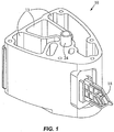
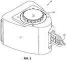
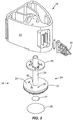
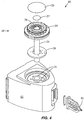
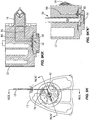
- Figs. 1-4 show a fluid control and processing system 10 including a housing 12 having a plurality of chambers 13.
- Fig. 1 shows the chambers 13 exposed for illustrative purposes.
- a top cover will typically be provided to enclose the chambers 13.
- a fluid control device 16 and a reaction vessel 18 are connected to different portions of the housing 12.
- the fluid control device in the embodiment shown is a rotary fluid control valve 16.
- the valve 16 includes a valve body 20 having a disk portion 22 and a tubular portion 24.
- the disk portion 22 has a generally planar external port surface 23, as best seen in Fig. 3 .
- the valve 16 is rotatable relative to the housing 12.
- the housing 12 includes a plurality of chamber ports 25 facing the external port surface 23 of the disk portion 22 of the valve 16 ( Fig. 4 ) to permit fluidic communication between the chambers 13 and the valve 16.
- a optional seal or gasket 26 is disposed between the disk portion 22 and the housing 12.
- the disk portion 22 further includes a filter or a filter stack 27 and an outer cover 28, and a toothed periphery 29.
- the cover 28 may be a rigid shell or a flexible film.
- the disk portion 22 includes a fluid sample processing region 30.
- the term "fluid sample processing region" refers to a region in which a fluid sample is subject to processing including, without limitation, chemical, optical, electrical, mechanical, thermal, or acoustical processing.
- chemical processing may include a catalyst; optical processing may include U.V. activation; electrical processing may include electroporation or electrophoresis; mechanical processing may include filtering, pressurization, and cell disruption; thermal processing may include heating or cooling; and acoustical processing may include the use of ultrasound.
- the fluid sample processing region may include an active member, such as the filter 27, to facilitate processing of the fluid.
- active members include a micro fluidic chip, a solid phase material, a filter or a filter stack, an affinity matrix, a magnetic separation matrix, a size exclusion column, a capillary tube, or the like.
- Suitable solid phase materials include, without limitation, beads, fibers, membranes, filter paper, glass wool, polymers, or gels.
- the fluid sample processing region is used to prepare a sample for further processing, for instance, in the reaction vessel 18.
- the outer cover 28 encloses the fluid sample processing region 30 and the bottom end of the disk portion 22 of the valve 16.
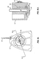
- the processing region 30 includes a first fluid processing port 32 coupled to a first fluid processing channel 34, and a second fluid processing port 36 coupled to a second fluid processing channel 38.
- the first fluid processing channel 34 is coupled to a first outer conduit 40 ending at a first external port 42 at the external port surface 23, while the second fluid processing channel 38 is coupled to a second outer conduit 44 ending at a second external port 46 at the external port surface 23.
- a fluid displacement channel 48 is coupled to the first fluid processing channel 34 and first conduit 40 near one end, and to a fluid displacement chamber 50 at the other end.
- the first outer conduit 40 serves as a common conduit for allowing fluidic communication between the first external port 42 and either or both of the first fluid processing channel 34 and the fluid displacement channel 48.
- the processing region 30 is in continuous fluidic communication with the fluid displacement chamber 50.
- the external ports 42, 46 are angularly spaced from one another relative to the axis 52 of the valve 16 by about 180°.
- the external ports 42, 46 are spaced radially by the same distance from the axis 52.
- the axis 52 is perpendicular to the external port surface 23.
- the angular spacing between the external ports 42, 46 may be different.
- the configuration of the channels in the disk portion 22 may also be different in another embodiment.
- the first fluid processing channel 34 and the first outer conduit 40 may be slanted and coupled directly with the fluid displacement chamber 50, thereby eliminating the fluid displacement channel 48.
- the second fluid displacement channel 38 may also be slanted and extend between the second fluid processing port 36 and the second external port 46 via a straight line, thereby eliminating the second outer conduit 44.
- more channels and external ports may be provided in the valve 16.
- a crossover channel or groove 56 is desirably provided on the external port surface 23.
- the groove 56 is curved and desirably is spaced from the axis 52 by a constant radius.
- the groove 56 is a circular arc lying on a common radius from the axis 52. As discussed in more detail below, the groove 56 is used for filling the vessel.
- the fluid displacement chamber 50 is disposed substantially within the tubular portion 24 of the valve 16 and extends partially into the disk portion 22.
- a fluid displacement member in the form of a plunger or piston 54 is movably disposed in the chamber 50. When the piston 54 moves upward, it expands the volume of the chamber 50 to produce a suction for drawing fluid into the chamber 50. When the piston 54 moves downward, it decreases the volume of the chamber 50 to drive fluid out of the chamber 50.
- one of the external ports 42, 46 maybe open and fluidicly coupled with one of the chambers 13 or reaction vessel 18, or both external ports 42, 46 may be blocked or closed. In this embodiment, at most only one of the external ports 42, 46 is fluidicly coupled with one of the chambers or reaction vessel 18. Other embodiments may be configured to permit both external ports 42, 46 to be fluidicly coupled with separate chambers or the reaction vessel 18.
- the valve 16 is rotatable with respect to the housing 12 to allow the external ports 42, 46 to be placed selectively in fluidic communication with a plurality of chambers which include the chambers 13 and the reaction vessel 18.
- the external ports 42, 46 can each switch from being an inlet port to an outlet port, and the fluid flow may pass through the processing region 30 or bypass the processing region 30.
- the first external port 42 is the inlet port so that the inlet side of the processing region 30 is closer to the fluid displacement chamber 54 than the outlet side of the processing region 30.
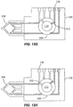
- FIGs. 9A-9LL illustrate the operation of the valve 16 for a specific protocol.
- the first external port 42 is placed in fluidic communication with a sample chamber 60 by rotating the valve 16, and the piston 54 is pulled upward to draw a fluid sample from the sample chamber 60 through the first outer conduit 40 and fluid displacement channel 48 to the fluid displacement chamber 50, bypassing the processing region 30.
- the piston 54 is not shown in Figs. 9A-9LL .
- the valve 16 is then rotated to place the second external port 46 in fluidic communication with a waste chamber 64 as shown in Figs. 9B and 9BB .
- the fluid sample processing region 30 includes a filter or a filter stack 27 for capturing sample components (e.g., cells, spores, microorganisms, viruses, proteins, or the like) from the fluid sample as it passes therethrough.
- sample components e.g., cells, spores, microorganisms, viruses, proteins, or the like
- FIG. 09/584,327 An example of a filter stack is described in commonly assigned, copending U.S. Patent Application No. 09/584,327 , entitled “Apparatus and Method for Cell Disruption,” filed May 30, 2000.
- other active members may be provided in the processing region 30. These first two steps of capturing sample components may be repeated as desired.
- valve 16 is rotated to place the first external port 42 in fluidic communication with a wash chamber 66, and the piston 54 is pulled upward to draw a wash fluid from the wash chamber 66 into the fluid displacement chamber 50, bypassing the processing region 30.
- the valve 16 is then rotated to place the second external port 46 in fluidic communication with the waste chamber 64 as shown in Figs. 9D and 9DD .
- the piston 54 is pushed downward to drive the wash fluid through the fluid sample processing region 30 to the waste chamber 64.
- the above washing steps may be repeated as desired.
- the intermediate washing is used to remove unwanted residue within the valve 16.
- Figs. 9E and 9EE the valve 16 is rotated to place the first external port 42 in fluidic communication with a lysate chamber 70, and the piston 54 is pulled upward to draw a lysate fluid (e.g., a lysing reagent or buffer) from the lysate chamber 70 into the fluid displacement chamber 50, bypassing the processing region 30.
- the valve 16 is then rotated to place the second external port 46 in fluidic communication with the waste chamber 64 as shown in Figs. 9F and 9FF .
- the piston 54 is pushed downward to drive the lysate fluid through the fluid sample processing region 30 to the waste chamber 64.
- Figs. 9G, and 9GG the valve 16 is rotated to close the external ports 42, 46.
- the piston 54 is pushed downward to pressurize the remaining lysate fluid and the sample components captured in the fluid sample processing region 30. Additional energy may be applied to the mixture in the processing region 30.
- a sonic member 76 such as an ultrasonic horn may be placed in contact with the outer cover 28 to transmit sonic energy into the processing region 30 to facilitate lysing of the sample components.
- the outer cover 28 is made of a flexible film which is stretched under pressure to contact the sonic member 76 during lysing to allow transmission of the sonic energy into the processing region 30.
- the cover 28 in one preferred embodiment is a flexible film of polymeric material such as polypropylene, polyethylene, polyester, or other polymers.
- the film may either be layered, e.g., laminates, or the films may be homogeneous. Layered films are preferred because they generally have better strength and structural integrity than homogeneous films.
- layered polypropylene films are presently preferred because polypropylene is not inhibitory to polymerase chain reaction (PCR).
- the cover 28 may comprise other materials such as a rigid piece of plastic.
- the energy transmitting member that is operatively coupled to the processing region 30 for transmitting energy thereto may be an ultrasonic, piezoelectric, magnetostrictive, or electrostatic transducer.
- the energy transmitting member may also be an electromagnetic device having a wound coil, such as a voice coil motor or a solenoid device.
- the energy transmitting member be a sonic member, such as an ultrasonic horn. Suitable horns are commercially available from Sonics & Materials, Inc. having an office at 53 Church Hill, Newton, Connecticut 06470-1614, U.S.A.
- the sonic member may comprise a piezoelectric disk or any other type of ultrasonic transducer that may be coupled to the cover 28.
- the energy transmitting member may be a thermal element (e.g., a heater) for transmitting thermal energy to the processing region 30 or an electrical element for transmitting electrical energy to the processing region 30.
- multiple energy transmitting members may be employed simultaneously, e.g., simultaneously heating and sonicating the processing region to effect lysis of cells, spores, viruses, or microorganisms trapped in the processing region.
- Figs. 9H and 9HH the valve 16 is rotated to place the second external port 46 in fluidic communication with a mastermix chamber 78, and the piston 54 is pushed downward to elute the mixture from the processing region 30 to the mastermix chamber 78.
- the mastermix chamber 78 typically contains reagents (e.g., PCR reagents and fluorescent probes) to be mixed with the sample. Any excess mixture is dispensed into the waste chamber 64 via the second external port 46 after rotating the valve 16 to place the port 46 in fluidic communication with the waste chamber 64, as shown in Figs. 9I and 9II . The mixture is then mixed in the mastermix chamber 78 by toggling.
- the valve 16 is rotated to place the first external port 42 in fluidic communication with a first branch 84 coupled to the reaction vessel 18, while the second branch 86 which is coupled to the reaction vessel 18 is placed in fluidic communication with the crossover groove 56.
- the first branch 84 and second branch 86 are disposed at different radii from the axis 52 of the valve 16, with the first branch 84 having a common radius with the first external port 42 and the second branch 86 having a common radius with the crossover groove 56.
- the crossover groove 56 is also in fluidic communication with the mastermix chamber 78 ( Fig. 9K ), and serves to bridge the gap between the mastermix chamber 78 and the second branch 86 to provide crossover flow therebetween.
- the external ports are disposed within a range of external port radii from the axis and the crossover groove is disposed within a range of crossover groove radii from the axis, where the range of external port radii and the range of crossover groove radii are non-overlapping. Placing the crossover groove 56 at a different radius from the radius of the external ports 42, 46 is advantageous because it avoids cross-contamination of the crossover groove 56 by contaminants that may be present in the area near the surfaces between the valve 16 and the housing 12 at the radius of the external ports 42, 46 as a result of rotational movement of the valve 16.
- crossover groove 56 is a preferred arrangement that isolates the crossover groove 56 from contamination from the area near the surfaces between the valve 16 and the housing 12 at the radius of the external ports 42, 46.
- the piston 54 is pulled upward to draw the mixture in the mastermix chamber 78 through the crossover groove 56 and the second branch 86 into the reaction vessel 18.
- the reaction vessel 18 is the aspiration chamber or referred to as the first chamber
- the mastermix chamber 78 is the source chamber or referred to as the second chamber.
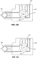
- the valve 16 is then rotated to place the second external port 46 in fluidic communication with the first branch 84 and to close the first external port 42, as shown in Figs. 9L and 9LL .
- the piston 54 is pushed downward to pressurize the mixture inside the reaction vessel 18.
- the reaction vessel 18 may be inserted into a thermal reaction chamber for performing nucleic acid amplification and/or detection.
- the two branches 84, 86 allow filling and evacuation of the reaction chamber of the reaction vessel 18.
- the vessel maybe connected to the housing 12 by ultrasonic welding, mechanical coupling, or the like, or be integrally formed with the housing 12 such as by molding.
- the use of a reaction vessel for analyzing a fluid sample is described in commonly assigned, copending U.S. Patent Application No. 09/584,328 , entitled “Cartridge for Conducting a Chemical Reaction,” filed May 30, 2000.
- a motor such as a stepper motor is typically coupled to the toothed periphery 29 of the disk portion 22 to rotate the valve 16 relative to the housing 12 for distributing fluid with high precision.
- the motor can be computer-controlled according to the desired protocol.
- a linear motor or the like is typically used to drive the piston 54 up and down with precision to provide accurate metering, and may also be computer-controlled according to the desired protocol.
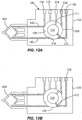
- Fig. 10 shows another valve 100 which is rotatably coupled to a fluid control channel housing or block 102.
- a reaction vessel 104 is detachably coupled to the housing 102.
- the valve 100 is a generally tubular member with a longitudinal axis 105 as shown in Fig. 11 .
- a piston 106 is movably connected to the valve 100 to change the volume of the fluid displacement chamber 108 as the piston 106 is moved up and down.
- a cover 109 is placed near the bottom of the valve 100.
- a fluid sample processing region 110 is disposed in the valve 100 and is in continuous fluidic communication with the fluid displacement chamber 108.
- the valve 100 includes a pair of apertures serving as a first port 111 and a second port 112, as best seen in Fig. 11 .
- the ports 111, 112 are angularly spaced by about 120°, but the spacing may be different in alternate embodiments.
- a crossover channel or groove 114 is formed on the external surface 116 of the valve 100 and extends generally in the longitudinal direction, as seen in Fig. 10 .
- the two ports 111, 112 are disposed at different levels longitudinally offset from one another along the longitudinal axis 105, and the crossover groove 114 extends in the longitudinal direction of the axis 105 bridging the two levels of the ports 111, 112.
- the housing 102 has an opening 118 for receiving the portion of the valve 100 having the ports 111, 112 and groove 114.
- the internal surface 120 around the opening 118 is shaped to cooperate with the external surface 116 of the valve 100.
- a gasket may be placed between the internal surface 120 and the external surface 116, a preferred embodiment employs tapered or conical surfaces 120, 116 that produce a sealing effect without the use of an additional gasket.
- the housing 102 includes a plurality of channels and ports and the valve 100 is rotatable around its axis 105 to allow the ports 111, 112 to be placed selectively in fluidic communication with the plurality of channels in the housing 102.
- the fluid flow in the valve 100 can change directions, and the ports 111, 112 can each switch from being an inlet port to an outlet port.
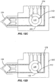
- Figs. 12A-12N illustrate the operation of the valve 100 for a specific protocol.
- the housing 102 includes a plurality of fluid channels.
- the channels are labeled as follows: mastermix channel 130, lysate channel 132, sample channel 134, wash channel 136, waste channel 138, first branch 140, and second branch 142.
- the channels 130-138 extend from the internal surface 120 to one external surface 144 which is generally planar, and the branches 140, 142 extend from the internal surface 120 to another external surface 146 which is also generally planar ( Fig. 10 ).
- the first port 111 and the channels 130-134 lie on a first transverse plane that is perpendicular to the longitudinal axis 105, while the second port 112, the channels 136, 138, and the two branches 140, 142 lie on a second transverse plane that is perpendicular to the longitudinal axis 105.
- the second transverse plane is longitudinally offset from the first transverse plane.
- the second port 112, the channels 136, 138, and the branches 140, 142 are shaded to indicate that they are longitudinally offset from the first port 111 and the channels 130-134.
- the crossover groove 114 extends longitudinally to bridge the offset between the first and second transverse planes.
- a chamber body 150 is connected to the housing 102 ( Fig. 10 ), and includes the mastermix chamber, lysate chamber, sample chamber, wash chamber, and waste chamber that are respectively coupled fluidicly with the channels 130-138.
- the first and second branches 140, 142 are fluidicly coupled with the reaction vessel 104.
- Fig. 12A the first port 111 is placed in fluidic communication with the sample channel 134 and the piston 106 is pulled upward to draw a fluid sample into the fluid displacement chamber 108 ( Fig. 11 ).
- the valve 100 is then rotated to place the second port 112 in fluidic communication with the waste channel 138 and the piston 106 is pushed downward to drive the fluid sample from the displacement chamber 108 through the processing region 110, and out through the waste channel 138, as shown in Fig. 12B .
- These steps are typically repeated until an entire sample is processed through the processing region 110, for instance, to capture sample components on a trapping member such as a filter.
- valve 100 is rotated to place the second port 112 in fluidic communication with the wash channel 136 to aspirate a wash fluid into the processing region 110 by pulling the piston 106 upward.
- the valve 100 is then rotated to place the second port 112 in fluidic communication with the waste channel 138 and the piston 106 is pushed downward to drive the wash fluid from the processing region 110 out through the waste channel 138.
- the above washing steps can be repeated as desired to remove unwanted residue inside the valve 100.
- valve 100 For lysing, the valve 100 is rotated to place the first port 111 in fluidic communication with the lysate channel 132 and the piston 106 is pulled upward to draw a lysate fluid into the fluid displacement chamber 108, as shown in Fig. 12E .
- Fig. 12F the valve 110 is rotated to close both ports 111, 112.
- the piston 106 is pushed downward to push the lysate fluid into the processing region 110 and to pressurize the lysate fluid and the sample components captured in the fluid sample processing region 110.
- Additional energy may be applied to the mixture in the processing region 110 including, for instance, sonic energy transmitted into the processing region 110 by operatively coupling a sonic member with the cover 109 ( Fig. 11 ).
- a desired preset amount of wash fluid is aspirated into the processing region 110 from the wash channel 136 through the second port 112 to dilute the mixture.
- the valve 100 is then rotated to place the first port 111 in fluidic communication with the mastermix channel 130 to discharge a preset amount of the mixture from the processing region 110 to the mastermix chamber, as shown in Fig. 12H .
- the piston 106 is moved up and down to agitate and mix the mixture by toggling.
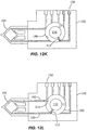
- the balance of the mixture is discharged through the second port 112 to the waste channel 138, as shown in Fig. 12I .
- Another wash is performed by drawing a wash fluid from the wash channel 136 through the second port 112 into the processing region 110 ( Fig. 12J ), and discharging the wash fluid from the processing region 110 through the second port 112 to the waste channel 138 ( Fig. 12K ).
- the valve 100 is rotated to place the second port 112 in fluidic communication with the first branch 140 coupled to the reaction vessel 104, while the second branch 142 which is coupled to the reaction vessel 104 is placed in fluidic communication with the crossover groove 114.
- the second branch 142 is longitudinal offset from the mastermix channel 130.
- the crossover groove 114 extends longitudinally to bridge the offset between the second branch 142 and the mastermix channel 130 to place them in fluidic communication with one another.
- the fluid sample processing region 110 is in fluidic communication, through the first branch 140, the reaction vessel 104, the second branch 142, and the crossover groove 114, with the mastermix channel 130.
- the piston 106 By pulling the piston 106 upward, the mixture in the mastermix chamber is drawn from the mastermix channel 130 through the crossover groove 114 and the second branch 142 into the reaction vessel 104.
- the valve 100 is then rotated to place the second port 112 in fluidic communication with the second branch 142 and to close the first port 111, as shown in Fig. 12M .
- the piston 106 is pushed downward to pressurize the mixture inside the reaction vessel 104.
- the valve 100 In Fig. 12N , the valve 100 is rotated to close the ports 111, 112 and isolate the reaction vessel 104.
- the reaction vessel 104 may be inserted into a thermal reaction chamber for performing nucleic acid amplification and/or detection.
- the fluid control and processing system is advantageously a fully contained system that is versatile and adaptable.
- the fluid displacement chamber is the motivating force for moving fluid in the system. By maintaining a continuous fluidic communication between the fluid displacement chamber and the fluid sample processing region, the motivating force for moving fluid in the system is fluidicly coupled to the processing region at all times.
- the fluid displacement chamber (motivating force) also acts as a temporary storage area for the fluid being driven through the system. A single motivating force is used to move fluid through the system. While the embodiments shown employ a moving piston in the fluid displacement chamber as the motivating force, other mechanisms may be used including, e.g., pneumatic pump mechanisms or the like which use pressure as the motivating force without a change in volume of the fluid displacement chamber.
- the inlet or outlet side of the fluid sample processing region can address any of the chambers to permit random access to reagents and other fluids.
- Complex protocols can be programmed relatively easily into a computer controller and then executed using the versatile fluid control and processing system. A myriad of different protocols can be performed using a single platform.
- the fluid control occurs by addressing a pair of ports in the valve to place only one port at a time selectively in fluidic communication with the chambers. This is accomplished by keeping the pair of ports out of phase relative to the chambers.
- a crossover or bypass channel provides additional fluid control capability (e.g., allowing convenient filling and emptying of the reaction vessel within the closed system).
- different porting schemes may be used to achieve the desired fluid control in other embodiments.
- each include a single fluid sample processing region in the valve body, additional processing regions can be located in the valve body if desired.
- the valve body needs (n+1) ports per n processing regions.
- the use of a single valve produces high manufacturing yields due to the presence of only one failure element.
- the concentration of the fluid control and processing components results in a compact apparatus (e.g., in the form of a small cartridge) and facilitates automated molding and assembly.
- the system advantageously includes dilution and mixing capability, intermediate wash capability, and positive pressurization capability.
- the fluid paths inside the system are normally closed to minimize contamination and facilitate containment and control of fluids within the system.
- the reaction vessel is conveniently detachable and replaceable, and may be disposable in some embodiments.
- the components of the fluid control and processing system may be made of a variety of materials that are compatible with the fluids being used.
- suitable materials include polymeric materials such as polypropylene, polyethylene, polycarbonate, acrylic, or nylon.
- the various chambers, channels, ports, and the like in the system may have various shapes and sizes.
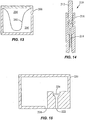
- Fig. 13 shows a soft-walled chamber 200 that may be incorporated into the fluid control and processing system.
- an on-board reagent style cartridge requires a total fluid volume of at least twice the total volume of reagents and sample combined in rigid systems.
- the use of soft-walled chambers can reduce the required volume.
- These chambers have flexible walls, and can typically be formed using films and thermoforming. An added advantage of soft walls is that venting need not be provided if the walls are sufficiently flexible to allow them to collapse when the chamber is emptied.
- a flexible sidewall 202 separates a reagent chamber 204 and a waste chamber 206.
- the volume required for waste is no more than the sum of the sample and reagents.
- the reagent chamber 204 contracts while the waste chamber 206 expands, and vice versa. This can be a closed system with no connection to the exterior.
- the configuration can reduce the overall size of the cartridge, and can allow fast change-overs of chamber volumes. It can also eliminate venting, and can cut costs by reducing the number of platforms that would otherwise need to be built with hard tooling.
- at least two of the plurality of chambers in the system are separated by a flexible wall to permit change-over of chamber volumes between the chambers.
- Fig. 14 shows a piston assembly 210 including a piston rod 212 connected to a piston shaft 214 having a smaller cross-section than the rod 212 for driving small amounts of fluids.
- the thin piston shaft 214 may bend under an applied force if it is too long: The piston rod 212 moves along the upper portion of the barrel or housing 216, while the piston shaft 214 moves along the lower portion of the barrel 216. The movement of the piston rod 212 guides the movement of the piston shaft 214, and absorbs much of the applied force so that very little bending force is transmitted to the thin piston shaft 214.
- Fig. 15 shows a side chamber 220 that may be incorporated into the system.
- the side chamber 220 includes an inlet port 222 and an outlet port 224.
- the side chamber 220 includes a filter 226 disposed at the inlet port 222. Fluid is directed to flow via the inlet port 222 into the side chamber 220 and out via the outlet port 224 for side filtering.
- the fluid may be recirculated to achieve better filtering by the filter 226.
- This prefiltering is useful to remove particles before introducing the fluid into the main chambers of the system to prevent clogging.
- the use of a side chamber is advantageous, for instance, to avoid contaminating the valve and the main chambers in the system.
Landscapes
- Health & Medical Sciences (AREA)
- Chemical & Material Sciences (AREA)
- Analytical Chemistry (AREA)
- General Health & Medical Sciences (AREA)
- Immunology (AREA)
- Biochemistry (AREA)
- Life Sciences & Earth Sciences (AREA)
- General Physics & Mathematics (AREA)
- Physics & Mathematics (AREA)
- Pathology (AREA)
- Hematology (AREA)
- Clinical Laboratory Science (AREA)
- Chemical Kinetics & Catalysis (AREA)
- Automatic Analysis And Handling Materials Therefor (AREA)
- Sampling And Sample Adjustment (AREA)
- Apparatus Associated With Microorganisms And Enzymes (AREA)
- Electrical Discharge Machining, Electrochemical Machining, And Combined Machining (AREA)
Abstract
Description
- The present disclosure relates generally to fluid manipulation and, more particularly, to a system and method for metering and distributing fluid for processing and analysis.
- The analysis of fluids such as clinical or environmental fluids generally involves a series of processing steps, which may include chemical, optical, electrical, mechanical, thermal, or acoustical processing of the fluid samples. Whether incorporated into a bench-top instrument, a disposable cartridge, or a combination of the two, such processing typically involves complex fluidic assemblies and processing algorithms.
- Conventional systems for processing fluid samples employ a series of chambers each configured for subjecting the fluid sample to a specific processing step. As the fluid sample flows through the system sequentially from chamber to chamber, the fluid sample undergoes the processing steps according to a specific protocol. Because different protocols require different configurations, conventional systems employing such sequential processing arrangements are not versatile or easily adaptable to different protocols.
-
EP 0481 285 A2 discloses valve assemblies for multi-path flow regulation that have a housing with a common port, and a valve plug contained within the housing. They also have n peripheral ports, where n is an even number of 4 or more. The valve plug has a distribution channel capable of fluid communication with the common port and at least one peripheral ports. There are also (n/2)-1 switching channels capable of fluid communication with at least two peripheral ports. - The present disclosure provides an apparatus and method for manipulating fluids. The present invention provides a fluid control and processing system for controlling fluid flow between a valve body and a plurality of chambers according to claim 1. The system the system comprises the valve body and the plurality of chambers, and the valve body encompasses within the valve body a plurality of external ports and a fluid displacement chamber continuously coupled fluidicly with a fluid sample processing region chamber which is simultaneously fluidicly coupled with at least two of the external ports, wherein the valve body is adjustable with respect to the plurality of chambers to place the external ports selectively in fluidic communication with the plurality of chambers. Embodiments of the invention facilitate processing of a fluid sample according to different protocols using the same apparatus, for instance, to determine the presence or absence of an analyte in the sample. In a specific embodiment, the apparatus employs a rotary valve configuration that allows fluidic communication between a fluid sample processing region (chamber) selectively with a plurality of chambers including, for example, a sample chamber, a waste chamber, a wash chamber, a lysate chamber, and a mastermix chamber. The fluid flow among the fluid sample processing region and the chambers is controlled by adjusting the position of the rotary valve. In this way, the metering and distribution of fluids in the apparatus can be varied depending on the specific protocol. Unlike conventional devices, the fluid flow is no longer limited to a specific protocol. As a result, the apparatus is more versatile and robust, and is adaptable to different protocols.
- In accordance with an aspect of the present disclosure, a fluid control and processing system for controlling fluid flow among a plurality of chambers comprises a body including a fluid sample processing region continuously coupled fluidicly with a fluid displacement chamber. The fluid displacement chamber is depressurizable to draw fluid into the fluid displacement chamber and pressurizable to expel fluid from the fluid displacement chamber. The body includes a plurality of external ports. The fluid sample processing region includes a plurality of fluid processing ports each fluidicly coupled with one of the external ports. The fluid displacement chamber is fluidicly coupled with at least one of the external ports. The body is adjustable with respect to the plurality of chambers to allow the external ports to be placed selectively in fluidic communication with the plurality of chambers.
- In some embodiments, the body is adjustable with respect to the chambers to place one external port at a time in fluidic communication with one of the plurality of chambers. The fluid sample processing region is disposed between the fluid displacement chamber and at least one external port. The fluid sample processing region comprises an active member which includes, for example, a microfluidic chip, a solid phase material, a filter or a filter stack, an affinity matrix, a magnetic separation matrix, a size exclusion column, a capillary tube, or the like. An energy transmitting member is operatively coupled with the fluid sample processing region for transmitting energy thereto to process fluid contained therein. In one embodiment, the body includes a crossover channel, and the body is adjustable with respect to the plurality of chambers to place the crossover channel in fluidic communication between two of the chambers.
- In accordance with another aspect of the disclosure, a fluid control and processing system for controlling fluid flow among a plurality of chambers comprises a body including a fluid sample processing region continuously coupled fluidicly with a fluid displacement chamber. The fluid displacement chamber is depressurizable to draw fluid into the fluid displacement chamber and pressurizable to expel fluid from the fluid displacement chamber. The body includes a plurality of external ports. The fluid sample processing region is fluidicly coupled with at least two of the external ports. The fluid displacement chamber is fluidicly coupled with at least one of the external ports. The body is adjustable with respect to the plurality of chambers to place at least one of the external ports selectively in fluidic communication with the plurality of chambers.
- In some embodiments, the body is adjustable with respect to the plurality of chambers to place at most one external port at a time in fluidic communication with one of the plurality of chambers. The body is also adjustable with respect to the plurality of chambers to close the external ports so that the fluid displacement chamber and sample fluid processing region are fluidicly isolated from the chambers. The fluid sample processing region comprises a trapping member for trapping sample components (e.g., cells, spores, viruses, large or small molecules, or proteins) of a fluid sample. The trapping member may comprise one or more filters, a microfluidic chip, filter paper, beads, fibers, a membrane, glass wool, polymers, or gel.
- Another aspect of the disclosure is a method for controlling fluid flow between a valve and a plurality of chambers. The valve includes a plurality of external ports and a fluid displacement chamber continuously coupled fluidicly with a fluid sample processing region which is fluidicly coupled with at least two of the external ports. The method comprises adjusting the valve with respect to the plurality of chambers to place the external ports selectively in fluidic communication with the plurality of chambers.
-
-
Fig. 1 is a perspective view of the fluid control and processing system according to an embodiment of the present invention; -
Fig. 2 is another perspective view of the system ofFig. 1 ; -
Fig. 3 is an exploded view of the system ofFig. 1 ; -
Fig. 4 is an exploded view of the system ofFig. 2 ; -
Fig. 5 is an elevational view of a fluid control apparatus and gasket in the system ofFig. 1 ; -
Fig. 6 is a bottom plan view of the fluid control apparatus and gasket ofFig. 5 ; -
Fig. 7 is a top plan view of the fluid control apparatus and gasket ofFig. 5 ; -
Fig. 8 is a cross-sectional view of the rotary fluid control apparatus ofFig. 7 along 8-8; -
Figs. 9A-9LL are top plan views and cross-sectional views illustrating a specific protocol for controlling and processing fluid using the fluid control and processing system ofFig. 1 ; -
Fig. 10 is an exploded perspective view of the fluid control and processing system according to another embodiment of the present invention; -
Fig. 11 is a cross-sectional view of a fluid control apparatus in the system ofFig. 10 ; -
Figs. 12A-12N are plan views illustrating a specific protocol for controlling and processing fluid using the fluid control and processing system ofFig. 10 ; -
Fig. 13 is a cross-sectional view of a soft-walled chamber; -
Fig. 14 is a cross-sectional view of a piston assembly; and -
Fig. 15 is a cross-sectional view of a side filtering chamber. -
Figs. 1-4 show a fluid control andprocessing system 10 including ahousing 12 having a plurality ofchambers 13.Fig. 1 shows thechambers 13 exposed for illustrative purposes. A top cover will typically be provided to enclose thechambers 13. As best seen inFigs. 3 and4 , afluid control device 16 and areaction vessel 18 are connected to different portions of thehousing 12. The fluid control device in the embodiment shown is a rotaryfluid control valve 16. Thevalve 16 includes avalve body 20 having adisk portion 22 and atubular portion 24. Thedisk portion 22 has a generally planarexternal port surface 23, as best seen inFig. 3 . Thevalve 16 is rotatable relative to thehousing 12. Thehousing 12 includes a plurality ofchamber ports 25 facing theexternal port surface 23 of thedisk portion 22 of the valve 16 (Fig. 4 ) to permit fluidic communication between thechambers 13 and thevalve 16. A optional seal orgasket 26 is disposed between thedisk portion 22 and thehousing 12. Thedisk portion 22 further includes a filter or afilter stack 27 and anouter cover 28, and atoothed periphery 29. Thecover 28 may be a rigid shell or a flexible film. - As best seen in
Fig. 4 , thedisk portion 22 includes a fluidsample processing region 30. As used herein, the term "fluid sample processing region" refers to a region in which a fluid sample is subject to processing including, without limitation, chemical, optical, electrical, mechanical, thermal, or acoustical processing. For example, chemical processing may include a catalyst; optical processing may include U.V. activation; electrical processing may include electroporation or electrophoresis; mechanical processing may include filtering, pressurization, and cell disruption; thermal processing may include heating or cooling; and acoustical processing may include the use of ultrasound. The fluid sample processing region may include an active member, such as thefilter 27, to facilitate processing of the fluid. Examples of active members include a micro fluidic chip, a solid phase material, a filter or a filter stack, an affinity matrix, a magnetic separation matrix, a size exclusion column, a capillary tube, or the like. Suitable solid phase materials include, without limitation, beads, fibers, membranes, filter paper, glass wool, polymers, or gels. In a specific embodiment, the fluid sample processing region is used to prepare a sample for further processing, for instance, in thereaction vessel 18. - As shown in
Figs. 5-8 , theouter cover 28 encloses the fluidsample processing region 30 and the bottom end of thedisk portion 22 of thevalve 16. InFig. 8 , theprocessing region 30 includes a firstfluid processing port 32 coupled to a firstfluid processing channel 34, and a secondfluid processing port 36 coupled to a secondfluid processing channel 38. The firstfluid processing channel 34 is coupled to a firstouter conduit 40 ending at a firstexternal port 42 at theexternal port surface 23, while the secondfluid processing channel 38 is coupled to a secondouter conduit 44 ending at a secondexternal port 46 at theexternal port surface 23. Afluid displacement channel 48 is coupled to the firstfluid processing channel 34 andfirst conduit 40 near one end, and to afluid displacement chamber 50 at the other end. The firstouter conduit 40 serves as a common conduit for allowing fluidic communication between the firstexternal port 42 and either or both of the firstfluid processing channel 34 and thefluid displacement channel 48. Theprocessing region 30 is in continuous fluidic communication with thefluid displacement chamber 50. - As shown in
Figs. 6-8 , theexternal ports axis 52 of thevalve 16 by about 180°. Theexternal ports axis 52. Theaxis 52 is perpendicular to theexternal port surface 23. In another embodiment, the angular spacing between theexternal ports disk portion 22 may also be different in another embodiment. For example, the firstfluid processing channel 34 and the firstouter conduit 40 may be slanted and coupled directly with thefluid displacement chamber 50, thereby eliminating thefluid displacement channel 48. The secondfluid displacement channel 38 may also be slanted and extend between the secondfluid processing port 36 and the secondexternal port 46 via a straight line, thereby eliminating the secondouter conduit 44. In addition, more channels and external ports may be provided in thevalve 16. As best seen inFig. 3 , a crossover channel orgroove 56 is desirably provided on theexternal port surface 23. Thegroove 56 is curved and desirably is spaced from theaxis 52 by a constant radius. In one embodiment, thegroove 56 is a circular arc lying on a common radius from theaxis 52. As discussed in more detail below, thegroove 56 is used for filling the vessel. - As shown in
Fig. 8 , thefluid displacement chamber 50 is disposed substantially within thetubular portion 24 of thevalve 16 and extends partially into thedisk portion 22. A fluid displacement member in the form of a plunger orpiston 54 is movably disposed in thechamber 50. When thepiston 54 moves upward, it expands the volume of thechamber 50 to produce a suction for drawing fluid into thechamber 50. When thepiston 54 moves downward, it decreases the volume of thechamber 50 to drive fluid out of thechamber 50. - As the
rotary valve 16 is rotated around itsaxis 52 relative to thehousing 12 ofFigs. 1-4 , one of theexternal ports chambers 13 orreaction vessel 18, or bothexternal ports external ports reaction vessel 18. Other embodiments may be configured to permit bothexternal ports reaction vessel 18. Thus, thevalve 16 is rotatable with respect to thehousing 12 to allow theexternal ports chambers 13 and thereaction vessel 18. Depending on whichexternal port piston 54 is moved upward or downward, the fluid flow in thevalve 16 can change directions, theexternal ports processing region 30 or bypass theprocessing region 30. In a specific embodiment, the firstexternal port 42 is the inlet port so that the inlet side of theprocessing region 30 is closer to thefluid displacement chamber 54 than the outlet side of theprocessing region 30. - To demonstrate the fluid metering and distribution function of the
valve 16,Figs. 9A-9LL illustrate the operation of thevalve 16 for a specific protocol. InFigs. 9A and 9AA , the firstexternal port 42 is placed in fluidic communication with asample chamber 60 by rotating thevalve 16, and thepiston 54 is pulled upward to draw a fluid sample from thesample chamber 60 through the firstouter conduit 40 andfluid displacement channel 48 to thefluid displacement chamber 50, bypassing theprocessing region 30. For simplicity, thepiston 54 is not shown inFigs. 9A-9LL . Thevalve 16 is then rotated to place the secondexternal port 46 in fluidic communication with awaste chamber 64 as shown inFigs. 9B and 9BB . Thepiston 54 is pushed downward to drive the fluid sample through the fluidsample processing region 30 to thewaste chamber 64. In a specific embodiment, the fluidsample processing region 30 includes a filter or afilter stack 27 for capturing sample components (e.g., cells, spores, microorganisms, viruses, proteins, or the like) from the fluid sample as it passes therethrough. An example of a filter stack is described in commonly assigned, copendingU.S. Patent Application No. 09/584,327 processing region 30. These first two steps of capturing sample components may be repeated as desired. - In
Figs. 9C and 9CC , thevalve 16 is rotated to place the firstexternal port 42 in fluidic communication with awash chamber 66, and thepiston 54 is pulled upward to draw a wash fluid from thewash chamber 66 into thefluid displacement chamber 50, bypassing theprocessing region 30. Thevalve 16 is then rotated to place the secondexternal port 46 in fluidic communication with thewaste chamber 64 as shown inFigs. 9D and 9DD . Thepiston 54 is pushed downward to drive the wash fluid through the fluidsample processing region 30 to thewaste chamber 64. The above washing steps may be repeated as desired. The intermediate washing is used to remove unwanted residue within thevalve 16. - In
Figs. 9E and 9EE , thevalve 16 is rotated to place the firstexternal port 42 in fluidic communication with alysate chamber 70, and thepiston 54 is pulled upward to draw a lysate fluid (e.g., a lysing reagent or buffer) from thelysate chamber 70 into thefluid displacement chamber 50, bypassing theprocessing region 30. Thevalve 16 is then rotated to place the secondexternal port 46 in fluidic communication with thewaste chamber 64 as shown inFigs. 9F and 9FF . Thepiston 54 is pushed downward to drive the lysate fluid through the fluidsample processing region 30 to thewaste chamber 64. InFigs. 9G, and 9GG , thevalve 16 is rotated to close theexternal ports piston 54 is pushed downward to pressurize the remaining lysate fluid and the sample components captured in the fluidsample processing region 30. Additional energy may be applied to the mixture in theprocessing region 30. For instance, asonic member 76 such as an ultrasonic horn may be placed in contact with theouter cover 28 to transmit sonic energy into theprocessing region 30 to facilitate lysing of the sample components. In one embodiment, theouter cover 28 is made of a flexible film which is stretched under pressure to contact thesonic member 76 during lysing to allow transmission of the sonic energy into theprocessing region 30. - The
cover 28 in one preferred embodiment is a flexible film of polymeric material such as polypropylene, polyethylene, polyester, or other polymers. The film may either be layered, e.g., laminates, or the films may be homogeneous. Layered films are preferred because they generally have better strength and structural integrity than homogeneous films. In particular, layered polypropylene films are presently preferred because polypropylene is not inhibitory to polymerase chain reaction (PCR). Alternatively, thecover 28 may comprise other materials such as a rigid piece of plastic. - In general, the energy transmitting member that is operatively coupled to the
processing region 30 for transmitting energy thereto may be an ultrasonic, piezoelectric, magnetostrictive, or electrostatic transducer. The energy transmitting member may also be an electromagnetic device having a wound coil, such as a voice coil motor or a solenoid device. It is presently preferred that the energy transmitting member be a sonic member, such as an ultrasonic horn. Suitable horns are commercially available from Sonics & Materials, Inc. having an office at 53 Church Hill, Newton, Connecticut 06470-1614, U.S.A. Alternatively, the sonic member may comprise a piezoelectric disk or any other type of ultrasonic transducer that may be coupled to thecover 28. In alternative embodiments, the energy transmitting member may be a thermal element (e.g., a heater) for transmitting thermal energy to theprocessing region 30 or an electrical element for transmitting electrical energy to theprocessing region 30. In addition, multiple energy transmitting members may be employed simultaneously, e.g., simultaneously heating and sonicating the processing region to effect lysis of cells, spores, viruses, or microorganisms trapped in the processing region. - In
Figs. 9H and 9HH , thevalve 16 is rotated to place the secondexternal port 46 in fluidic communication with amastermix chamber 78, and thepiston 54 is pushed downward to elute the mixture from theprocessing region 30 to themastermix chamber 78. Themastermix chamber 78 typically contains reagents (e.g., PCR reagents and fluorescent probes) to be mixed with the sample. Any excess mixture is dispensed into thewaste chamber 64 via the secondexternal port 46 after rotating thevalve 16 to place theport 46 in fluidic communication with thewaste chamber 64, as shown inFigs. 9I and 9II . The mixture is then mixed in themastermix chamber 78 by toggling. This is carried out by placing thefluid displacement chamber 50 in fluidic communication with themastermix chamber 78 as shown inFigs. 9J and 9JJ , and moving thepiston 54 up and down. Toggling of the mixture through the filter in theprocessing region 30, for instance, allows larger particles trapped in the filter to temporarily move out of the way to permit smaller particles to pass through. - In
Figs. 9K, 9KK, and 9K'K' , thevalve 16 is rotated to place the firstexternal port 42 in fluidic communication with afirst branch 84 coupled to thereaction vessel 18, while thesecond branch 86 which is coupled to thereaction vessel 18 is placed in fluidic communication with thecrossover groove 56. Thefirst branch 84 andsecond branch 86 are disposed at different radii from theaxis 52 of thevalve 16, with thefirst branch 84 having a common radius with the firstexternal port 42 and thesecond branch 86 having a common radius with thecrossover groove 56. Thecrossover groove 56 is also in fluidic communication with the mastermix chamber 78 (Fig. 9K ), and serves to bridge the gap between themastermix chamber 78 and thesecond branch 86 to provide crossover flow therebetween. The external ports are disposed within a range of external port radii from the axis and the crossover groove is disposed within a range of crossover groove radii from the axis, where the range of external port radii and the range of crossover groove radii are non-overlapping. Placing thecrossover groove 56 at a different radius from the radius of theexternal ports crossover groove 56 by contaminants that may be present in the area near the surfaces between thevalve 16 and thehousing 12 at the radius of theexternal ports valve 16. Thus, while other configurations of the crossover groove may be used including those that overlap with the radius of theexternal ports crossover groove 56 from contamination from the area near the surfaces between thevalve 16 and thehousing 12 at the radius of theexternal ports - To fill the
reaction vessel 18, thepiston 54 is pulled upward to draw the mixture in themastermix chamber 78 through thecrossover groove 56 and thesecond branch 86 into thereaction vessel 18. In such an arrangement, thereaction vessel 18 is the aspiration chamber or referred to as the first chamber, and themastermix chamber 78 is the source chamber or referred to as the second chamber. Thevalve 16 is then rotated to place the secondexternal port 46 in fluidic communication with thefirst branch 84 and to close the firstexternal port 42, as shown inFigs. 9L and 9LL . Thepiston 54 is pushed downward to pressurize the mixture inside thereaction vessel 18. Thereaction vessel 18 may be inserted into a thermal reaction chamber for performing nucleic acid amplification and/or detection. The twobranches reaction vessel 18. The vessel maybe connected to thehousing 12 by ultrasonic welding, mechanical coupling, or the like, or be integrally formed with thehousing 12 such as by molding. The use of a reaction vessel for analyzing a fluid sample is described in commonly assigned, copendingU.S. Patent Application No. 09/584,328 - To operate the
valve 16 ofFigs. 3-8 , a motor such as a stepper motor is typically coupled to thetoothed periphery 29 of thedisk portion 22 to rotate thevalve 16 relative to thehousing 12 for distributing fluid with high precision. The motor can be computer-controlled according to the desired protocol. A linear motor or the like is typically used to drive thepiston 54 up and down with precision to provide accurate metering, and may also be computer-controlled according to the desired protocol. -
Fig. 10 shows anothervalve 100 which is rotatably coupled to a fluid control channel housing or block 102. Areaction vessel 104 is detachably coupled to thehousing 102. Thevalve 100 is a generally tubular member with alongitudinal axis 105 as shown inFig. 11 . Apiston 106 is movably connected to thevalve 100 to change the volume of thefluid displacement chamber 108 as thepiston 106 is moved up and down. Acover 109 is placed near the bottom of thevalve 100. A fluidsample processing region 110 is disposed in thevalve 100 and is in continuous fluidic communication with thefluid displacement chamber 108. Thevalve 100 includes a pair of apertures serving as afirst port 111 and asecond port 112, as best seen inFig. 11 . In the embodiment shown, theports external surface 116 of thevalve 100 and extends generally in the longitudinal direction, as seen inFig. 10 . The twoports longitudinal axis 105, and thecrossover groove 114 extends in the longitudinal direction of theaxis 105 bridging the two levels of theports - The
housing 102 has anopening 118 for receiving the portion of thevalve 100 having theports groove 114. Theinternal surface 120 around theopening 118 is shaped to cooperate with theexternal surface 116 of thevalve 100. Although a gasket may be placed between theinternal surface 120 and theexternal surface 116, a preferred embodiment employs tapered orconical surfaces housing 102 includes a plurality of channels and ports and thevalve 100 is rotatable around itsaxis 105 to allow theports housing 102. Depending on which port is opened or closed and whether thepiston 106 is moved upward or downward, the fluid flow in thevalve 100 can change directions, and theports - To demonstrate the fluid metering and distribution function of the
valve 100,Figs. 12A-12N illustrate the operation of thevalve 100 for a specific protocol. As shown inFig. 12A , thehousing 102 includes a plurality of fluid channels. For convenience, the channels are labeled as follows:mastermix channel 130,lysate channel 132,sample channel 134,wash channel 136,waste channel 138,first branch 140, andsecond branch 142. The channels 130-138 extend from theinternal surface 120 to oneexternal surface 144 which is generally planar, and thebranches internal surface 120 to anotherexternal surface 146 which is also generally planar (Fig. 10 ). When assembled, thefirst port 111 and the channels 130-134 lie on a first transverse plane that is perpendicular to thelongitudinal axis 105, while thesecond port 112, thechannels branches longitudinal axis 105. The second transverse plane is longitudinally offset from the first transverse plane. For convenience, thesecond port 112, thechannels branches first port 111 and the channels 130-134. Thecrossover groove 114 extends longitudinally to bridge the offset between the first and second transverse planes. Achamber body 150 is connected to the housing 102 (Fig. 10 ), and includes the mastermix chamber, lysate chamber, sample chamber, wash chamber, and waste chamber that are respectively coupled fluidicly with the channels 130-138. The first andsecond branches reaction vessel 104. - In
Fig. 12A , thefirst port 111 is placed in fluidic communication with thesample channel 134 and thepiston 106 is pulled upward to draw a fluid sample into the fluid displacement chamber 108 (Fig. 11 ). Thevalve 100 is then rotated to place thesecond port 112 in fluidic communication with thewaste channel 138 and thepiston 106 is pushed downward to drive the fluid sample from thedisplacement chamber 108 through theprocessing region 110, and out through thewaste channel 138, as shown inFig. 12B . These steps are typically repeated until an entire sample is processed through theprocessing region 110, for instance, to capture sample components on a trapping member such as a filter. - In
Fig. 12C , thevalve 100 is rotated to place thesecond port 112 in fluidic communication with thewash channel 136 to aspirate a wash fluid into theprocessing region 110 by pulling thepiston 106 upward. Thevalve 100 is then rotated to place thesecond port 112 in fluidic communication with thewaste channel 138 and thepiston 106 is pushed downward to drive the wash fluid from theprocessing region 110 out through thewaste channel 138. The above washing steps can be repeated as desired to remove unwanted residue inside thevalve 100. - For lysing, the
valve 100 is rotated to place thefirst port 111 in fluidic communication with thelysate channel 132 and thepiston 106 is pulled upward to draw a lysate fluid into thefluid displacement chamber 108, as shown inFig. 12E . InFig. 12F , thevalve 110 is rotated to close bothports piston 106 is pushed downward to push the lysate fluid into theprocessing region 110 and to pressurize the lysate fluid and the sample components captured in the fluidsample processing region 110. Additional energy may be applied to the mixture in theprocessing region 110 including, for instance, sonic energy transmitted into theprocessing region 110 by operatively coupling a sonic member with the cover 109 (Fig. 11 ). - In
Fig. 12G , a desired preset amount of wash fluid is aspirated into theprocessing region 110 from thewash channel 136 through thesecond port 112 to dilute the mixture. Thevalve 100 is then rotated to place thefirst port 111 in fluidic communication with themastermix channel 130 to discharge a preset amount of the mixture from theprocessing region 110 to the mastermix chamber, as shown inFig. 12H . Thepiston 106 is moved up and down to agitate and mix the mixture by toggling. The balance of the mixture is discharged through thesecond port 112 to thewaste channel 138, as shown inFig. 12I . Another wash is performed by drawing a wash fluid from thewash channel 136 through thesecond port 112 into the processing region 110 (Fig. 12J ), and discharging the wash fluid from theprocessing region 110 through thesecond port 112 to the waste channel 138 (Fig. 12K ). - In
Fig. 12L , thevalve 100 is rotated to place thesecond port 112 in fluidic communication with thefirst branch 140 coupled to thereaction vessel 104, while thesecond branch 142 which is coupled to thereaction vessel 104 is placed in fluidic communication with thecrossover groove 114. Thesecond branch 142 is longitudinal offset from themastermix channel 130. In the position as shown inFig. 12L , thecrossover groove 114 extends longitudinally to bridge the offset between thesecond branch 142 and themastermix channel 130 to place them in fluidic communication with one another. As a result, the fluidsample processing region 110 is in fluidic communication, through thefirst branch 140, thereaction vessel 104, thesecond branch 142, and thecrossover groove 114, with themastermix channel 130. - By pulling the
piston 106 upward, the mixture in the mastermix chamber is drawn from themastermix channel 130 through thecrossover groove 114 and thesecond branch 142 into thereaction vessel 104. Thevalve 100 is then rotated to place thesecond port 112 in fluidic communication with thesecond branch 142 and to close thefirst port 111, as shown inFig. 12M . Thepiston 106 is pushed downward to pressurize the mixture inside thereaction vessel 104. InFig. 12N , thevalve 100 is rotated to close theports reaction vessel 104. Thereaction vessel 104 may be inserted into a thermal reaction chamber for performing nucleic acid amplification and/or detection. - As illustrated in the above embodiments, the fluid control and processing system is advantageously a fully contained system that is versatile and adaptable. The fluid displacement chamber is the motivating force for moving fluid in the system. By maintaining a continuous fluidic communication between the fluid displacement chamber and the fluid sample processing region, the motivating force for moving fluid in the system is fluidicly coupled to the processing region at all times. The fluid displacement chamber (motivating force) also acts as a temporary storage area for the fluid being driven through the system. A single motivating force is used to move fluid through the system. While the embodiments shown employ a moving piston in the fluid displacement chamber as the motivating force, other mechanisms may be used including, e.g., pneumatic pump mechanisms or the like which use pressure as the motivating force without a change in volume of the fluid displacement chamber. The inlet or outlet side of the fluid sample processing region can address any of the chambers to permit random access to reagents and other fluids. Complex protocols can be programmed relatively easily into a computer controller and then executed using the versatile fluid control and processing system. A myriad of different protocols can be performed using a single platform.
- In the embodiments shown, the fluid control occurs by addressing a pair of ports in the valve to place only one port at a time selectively in fluidic communication with the chambers. This is accomplished by keeping the pair of ports out of phase relative to the chambers. A crossover or bypass channel provides additional fluid control capability (e.g., allowing convenient filling and emptying of the reaction vessel within the closed system). Of course, different porting schemes may be used to achieve the desired fluid control in other embodiments. Moreover, while the embodiments shown each include a single fluid sample processing region in the valve body, additional processing regions can be located in the valve body if desired. Generally, the valve body needs (n+1) ports per n processing regions.
- The use of a single valve produces high manufacturing yields due to the presence of only one failure element. The concentration of the fluid control and processing components results in a compact apparatus (e.g., in the form of a small cartridge) and facilitates automated molding and assembly. As discussed above, the system advantageously includes dilution and mixing capability, intermediate wash capability, and positive pressurization capability. The fluid paths inside the system are normally closed to minimize contamination and facilitate containment and control of fluids within the system. The reaction vessel is conveniently detachable and replaceable, and may be disposable in some embodiments.
- The components of the fluid control and processing system may be made of a variety of materials that are compatible with the fluids being used. Examples of suitable materials include polymeric materials such as polypropylene, polyethylene, polycarbonate, acrylic, or nylon. The various chambers, channels, ports, and the like in the system may have various shapes and sizes.
- The above-described arrangements of apparatus and methods are merely illustrative of applications of the principles of this invention and many other embodiments and modifications may be made without departing from the scope of the invention as defined in the claims.
- For instance,
Fig. 13 shows a soft-walled chamber 200 that may be incorporated into the fluid control and processing system. Typically, an on-board reagent style cartridge requires a total fluid volume of at least twice the total volume of reagents and sample combined in rigid systems. The use of soft-walled chambers can reduce the required volume. These chambers have flexible walls, and can typically be formed using films and thermoforming. An added advantage of soft walls is that venting need not be provided if the walls are sufficiently flexible to allow them to collapse when the chamber is emptied. InFig. 13 , aflexible sidewall 202 separates areagent chamber 204 and awaste chamber 206. Because the waste is composed of the sample and reagents, the volume required for waste is no more than the sum of the sample and reagents. Thereagent chamber 204 contracts while thewaste chamber 206 expands, and vice versa. This can be a closed system with no connection to the exterior. The configuration can reduce the overall size of the cartridge, and can allow fast change-overs of chamber volumes. It can also eliminate venting, and can cut costs by reducing the number of platforms that would otherwise need to be built with hard tooling. In one embodiment, at least two of the plurality of chambers in the system are separated by a flexible wall to permit change-over of chamber volumes between the chambers. -
Fig. 14 shows apiston assembly 210 including apiston rod 212 connected to apiston shaft 214 having a smaller cross-section than therod 212 for driving small amounts of fluids. Thethin piston shaft 214 may bend under an applied force if it is too long: Thepiston rod 212 moves along the upper portion of the barrel orhousing 216, while thepiston shaft 214 moves along the lower portion of thebarrel 216. The movement of thepiston rod 212 guides the movement of thepiston shaft 214, and absorbs much of the applied force so that very little bending force is transmitted to thethin piston shaft 214. -
Fig. 15 shows aside chamber 220 that may be incorporated into the system. Theside chamber 220 includes aninlet port 222 and anoutlet port 224. In this example, theside chamber 220 includes afilter 226 disposed at theinlet port 222. Fluid is directed to flow via theinlet port 222 into theside chamber 220 and out via theoutlet port 224 for side filtering. This allows filtering of a fluid sample or the like using the fluid control system of the invention. The fluid may be recirculated to achieve better filtering by thefilter 226. This prefiltering is useful to remove particles before introducing the fluid into the main chambers of the system to prevent clogging. The use of a side chamber is advantageous, for instance, to avoid contaminating the valve and the main chambers in the system.
Claims (15)
- A fluid control and processing system (10) for controlling fluid flow between a valve body (20) and a plurality of chambers (13), wherein the system (10) comprises the valve body (20) and the plurality of chambers (13), characterized in that the valve body (20) encompasses within the valve body (20) a plurality of external ports (42,46,111,112) and a fluid displacement chamber (50, 108) the fluid displacement chamber being depressurizable to draw fluid into the fluid displacement chamber and pressurizable to expel fluid from the fluid displacement chamber, and being continuously coupled fluidicly with a fluid sample processing chamber (30,110) which is simultaneously fluidicly coupled with at least two of the external ports (42,46,111,112), wherein the valve body (20) is adjustable with respect to the plurality of chambers (13) to place the external ports (42,46,111,112) selectively in fluidic communication with the plurality of chambers (13).
- The fluid control and processing system (10) of claim 1, wherein the valve body (20) is adjustable to close the external ports (42,46,111,112) so that the valve body (20) is fluidicly isolated from the chambers (13).
- The fluid control and processing system (10) of claim 1, wherein the fluid displacement chamber (50,108) is depressurizable to draw fluid into the fluid displacement chamber (50,108) and pressurizable to expel fluid from the fluid displacement chamber (50,108).
- The fluid control and processing system (10) of claim 1, wherein the valve body (20) is adjustable to place one external port (42,46,111,112) in fluidic communication with one of the plurality of chambers (13), thereby allowing the fluid displacement chamber (50,108) to aspirate fluid from the chamber (13) into the valve body (20) when the fluid displacement chamber (50,108) is depressurized.
- The fluid control and processing system (10) of claim 1, wherein the valve body (20) is adjustable to place one external port (42,46,111,112) in fluidic communication with one of the plurality of chambers (13), thereby allowing the fluid displacement chamber (50,108) to expel fluid from the valve body (20) into the chamber (13) when the fluid displacement chamber (50,108) is pressurized.
- The fluid control and processing system (10) of claim 1, wherein the valve body (20) includes a crossover channel (56,114), and wherein the valve body (20) is adjustable to place one external port (42,46,111,112) in fluidic communication with a first chamber and to place the crossover channel (56,114) in fluidic communication with the first chamber and a second chamber.
- The fluid control and processing system (10) of claim 3, wherein the fluid displacement chamber (50,108) is depressurizable by increasing in volume and is pressurizable by decreasing in volume.
- The fluid control and processing system (10) of claim 7, further comprising a fluid displacement member (54,106,210) disposed in the fluid displacement chamber (50,108), the fluid displacement member (54,106,210) being movable to adjust the volume of the fluid displacement chamber (50,108).
- The fluid control and processing system (10) of claim 8, wherein the fluid displacement member (54,106,210) comprises a piston (54) movable in a linear direction in the fluid displacement chamber (50,108).
- The fluid control and processing system (10) of claim 9, wherein the fluid displacement member (54,106,210) comprises a piston shaft (214) which is connected to a distal portion of a piston rod (212) for driving the piston shaft (214) to move inside the fluid displacement chamber (50,108), the piston shaft (214) being smaller in cross-section than the piston rod (212).
- The fluid control and processing system (10) of claim 1, further comprising an energy transmitting member operatively coupled with the fluid sample processing chamber (30,110) for transmitting energy thereto to process fluid contained therein.
- The fluid control and processing system (10) of claim 11, further comprising a cover (28) disposed between the fluid sample processing chamber (30,110) and the energy transmitting member.
- The fluid control and processing system (10) of claim 12, wherein the cover (28) comprises a flexible film.
- The fluid control and processing system (10) of claim 13, wherein the energy transmitting member comprises a sonic member (76) for contacting the cover (28) to transmit sonic energy through the cover into the fluid sample processing chamber (30,110).
- The fluid control and processing system (10) of claim 1, wherein the fluid displacement chamber (50,108) and the fluid sample processing chamber (30,110) are two separate areas contained within the valve body (20).
Applications Claiming Priority (4)
| Application Number | Priority Date | Filing Date | Title |
|---|---|---|---|
| US09/648,570 US6374684B1 (en) | 2000-08-25 | 2000-08-25 | Fluid control and processing system |
| EP01957312A EP1325298B1 (en) | 2000-08-25 | 2001-07-26 | Fluid control and processing system |
| EP08015803.3A EP2017596B1 (en) | 2000-08-25 | 2001-07-26 | Fluid control and processing method |
| PCT/US2001/023776 WO2002018902A1 (en) | 2000-08-25 | 2001-07-26 | Fluid control and processing system |
Related Parent Applications (3)
| Application Number | Title | Priority Date | Filing Date |
|---|---|---|---|
| EP08015803.3A Division EP2017596B1 (en) | 2000-08-25 | 2001-07-26 | Fluid control and processing method |
| EP08015803.3A Division-Into EP2017596B1 (en) | 2000-08-25 | 2001-07-26 | Fluid control and processing method |
| EP01957312A Division EP1325298B1 (en) | 2000-08-25 | 2001-07-26 | Fluid control and processing system |
Publications (2)
| Publication Number | Publication Date |
|---|---|
| EP3153837A1 EP3153837A1 (en) | 2017-04-12 |
| EP3153837B1 true EP3153837B1 (en) | 2019-03-20 |
Family
ID=24601335
Family Applications (3)
| Application Number | Title | Priority Date | Filing Date |
|---|---|---|---|
| EP01957312A Expired - Lifetime EP1325298B1 (en) | 2000-08-25 | 2001-07-26 | Fluid control and processing system |
| EP08015803.3A Expired - Lifetime EP2017596B1 (en) | 2000-08-25 | 2001-07-26 | Fluid control and processing method |
| EP16184799.1A Expired - Lifetime EP3153837B1 (en) | 2000-08-25 | 2001-07-26 | Fluid control and processing system |
Family Applications Before (2)
| Application Number | Title | Priority Date | Filing Date |
|---|---|---|---|
| EP01957312A Expired - Lifetime EP1325298B1 (en) | 2000-08-25 | 2001-07-26 | Fluid control and processing system |
| EP08015803.3A Expired - Lifetime EP2017596B1 (en) | 2000-08-25 | 2001-07-26 | Fluid control and processing method |
Country Status (10)
| Country | Link |
|---|---|
| US (1) | US6374684B1 (en) |
| EP (3) | EP1325298B1 (en) |
| JP (9) | JP4663959B2 (en) |
| AT (1) | ATE408129T1 (en) |
| AU (2) | AU2001279070B2 (en) |
| CA (5) | CA2928259C (en) |
| DE (1) | DE60135766D1 (en) |
| DK (2) | DK1325298T3 (en) |
| ES (3) | ES2313972T3 (en) |
| WO (1) | WO2002018902A1 (en) |
Families Citing this family (146)
| Publication number | Priority date | Publication date | Assignee | Title |
|---|---|---|---|---|
| US8048386B2 (en) * | 2002-02-25 | 2011-11-01 | Cepheid | Fluid processing and control |
| US7217513B2 (en) * | 2001-07-10 | 2007-05-15 | Massachusetts Institute Of Technology | Apparatus and method for isolating a nucleic acid from a sample |
| DE10209732A1 (en) * | 2002-03-06 | 2003-10-09 | Endress & Hauser Gmbh & Co Kg | Protective casing for a field appliance, surrounds a field appliance casing in order to form a protective area around the field appliance casing. |
| DE10228917A1 (en) * | 2002-06-24 | 2004-01-22 | Epigenomics Ag | Device for handling liquids in a plurality of channels |
| JP2005532072A (en) * | 2002-07-10 | 2005-10-27 | マサチューセッツ・インスティテュート・オブ・テクノロジー | Apparatus and method for isolating nucleic acids from a sample |
| US20040101444A1 (en) * | 2002-07-15 | 2004-05-27 | Xeotron Corporation | Apparatus and method for fluid delivery to a hybridization station |
| US20040038385A1 (en) * | 2002-08-26 | 2004-02-26 | Langlois Richard G. | System for autonomous monitoring of bioagents |
| JP4554365B2 (en) * | 2002-09-11 | 2010-09-29 | テンプル・ユニバーシティ−オブ・ザ・コモンウェルス・システム・オブ・ハイアー・エデュケイション | An automated system for high-throughput electrophoretic separations. |
| WO2004083806A2 (en) | 2003-01-22 | 2004-09-30 | University Of South Florida | Autonomous genosensor apparatus and methods for use |
| ES2220227B1 (en) | 2003-05-30 | 2006-02-16 | INSTITUTO NACIONAL DE TECNICA AEROESPACIAL "ESTEBAN TERRADAS" | METHOD AND APPARATUS FOR THE DETECTION OF SUBSTANCES OR ANALYTICS FROM THE ANALYSIS OF ONE OR SEVERAL SAMPLES. |
| GB0319671D0 (en) | 2003-08-21 | 2003-09-24 | Secr Defence | Apparatus for processing a fluid sample |
| US7491527B2 (en) * | 2003-09-19 | 2009-02-17 | Microfluidic Systems, Inc. | Microfluidic differential extraction cartridge |
| US7541166B2 (en) * | 2003-09-19 | 2009-06-02 | Microfluidic Systems, Inc. | Sonication to selectively lyse different cell types |
| US7032605B1 (en) | 2003-10-15 | 2006-04-25 | Douglas B. Dority | Dual piston rotary valve |
| WO2005055804A2 (en) * | 2003-12-02 | 2005-06-23 | Musc Foundation For Research Development | Methods and compositions for diagnosing epithelial cell cancer |
| US7981616B2 (en) * | 2004-02-27 | 2011-07-19 | Musc Foundation For Research Development | Enhanced detection of RNA using a panel of truncated gene-specific primers for reverse transcription |
| US20050244837A1 (en) * | 2004-04-28 | 2005-11-03 | Cepheid | Method and device for sample preparation control |
| CA2571642A1 (en) | 2004-07-09 | 2006-02-16 | University Of Pittsburgh - Of The Commonwealth System Of Higher Educatio N | Identification of markers in lung and breast cancer |
| CA2583498A1 (en) * | 2004-09-09 | 2006-03-16 | Microfluidic Systems Inc. | A handheld and portable microfluidic device to automatically prepare nucleic acids for analysis |
| WO2006034215A2 (en) * | 2004-09-20 | 2006-03-30 | University Of Pittsburgh - Of The Commonwealth System Of Higher Education | Multiple mode multiplex reaction quenching method |
| US20080193961A1 (en) * | 2004-09-29 | 2008-08-14 | Easley Christopher J | Localized Control of Thermal Properties on Microdevices and Applications Thereof |
| US8056881B2 (en) | 2004-10-13 | 2011-11-15 | University Of Virginia Patent Foundation | Electrostatic actuation for management of flow in micro-total analysis systems (μ-TAS) and related method thereof |
| CA2587085C (en) * | 2004-10-27 | 2017-08-08 | Cepheid | Closed-system multi-stage nucleic acid amplification reactions |
| US7785868B2 (en) * | 2004-12-02 | 2010-08-31 | Microfluidic Systems, Inc. | Apparatus to automatically lyse a sample |
| JP4922185B2 (en) * | 2004-12-22 | 2012-04-25 | ユニバーシティ・オブ・ヴァージニア・パテント・ファウンデーション | Use of microwaves for thermal or non-thermal applications in micro or nanoscale devices |
| DE102005008224B3 (en) * | 2005-02-23 | 2006-06-14 | Directif Gmbh | Apparatus for automatically activating microfluid device, for carrying out biochemical purifications and assays, having activator controlled on the basis of measurements of exerted force |
| WO2007030240A2 (en) * | 2005-08-01 | 2007-03-15 | University Of Virginia Patent Foundation | Microdevices for chemical sensing and chemical actuation |
| CA2620285C (en) * | 2005-08-23 | 2016-08-16 | University Of Virginia Patent Foundation | Passive components for micro-fluidic flow profile shaping and related method thereof |
| WO2007041671A2 (en) * | 2005-10-04 | 2007-04-12 | University Of Virginia Patent Foundation | Microchip-based acoustic trapping or capture of cells for forensic analysis and related method thereof |
| WO2007047336A2 (en) * | 2005-10-12 | 2007-04-26 | University Of Virginia Patent Foundation | Integrated microfluidic analysis systems |
| CN101498655B (en) * | 2005-10-25 | 2012-05-30 | 阿莱瑞士股份有限公司 | Detecting instrument for liquid sample |
| CN100478671C (en) * | 2005-10-25 | 2009-04-15 | 艾康生物技术(杭州)有限公司 | Detector and method for liquid sampler |
| US8900828B2 (en) | 2006-05-01 | 2014-12-02 | Cepheid | Methods and apparatus for sequential amplification reactions |
| US20100216657A1 (en) * | 2006-05-16 | 2010-08-26 | Arcxis Biotechnologies, Inc. | Pcr-free sample preparation and detection systems for high speed biologic analysis and identification |
| JP2009540868A (en) * | 2006-06-15 | 2009-11-26 | ストラタジーン カリフォルニア | System for isolating biomolecules from samples |
| US20080153078A1 (en) * | 2006-06-15 | 2008-06-26 | Braman Jeffrey C | System for isolating biomolecules from a sample |
| US8119352B2 (en) * | 2006-06-20 | 2012-02-21 | Cepheld | Multi-stage amplification reactions by control of sequence replication times |
| FR2902799B1 (en) * | 2006-06-27 | 2012-10-26 | Millipore Corp | METHOD AND UNIT FOR PREPARING A SAMPLE FOR THE MICROBIOLOGICAL ANALYSIS OF A LIQUID |
| US8187557B2 (en) | 2006-07-13 | 2012-05-29 | Cepheid | Reagent reservoir system for analytical instruments |
| US7705739B2 (en) * | 2006-08-24 | 2010-04-27 | Microfluidic Systems, Inc. | Integrated airborne substance collection and detection system |
| US7633606B2 (en) * | 2006-08-24 | 2009-12-15 | Microfluidic Systems, Inc. | Integrated airborne substance collection and detection system |
| US7858366B2 (en) * | 2006-08-24 | 2010-12-28 | Microfluidic Systems, Inc | Integrated airborne substance collection and detection system |
| JP5553602B2 (en) * | 2006-09-06 | 2014-07-16 | キヤノン ユー.エス. ライフ サイエンシズ, インコーポレイテッド | Chip and cartridge design configuration for performing microfluidic assays |
| US20100028896A1 (en) * | 2006-12-19 | 2010-02-04 | Konica Minolta Medical & Graphic, Inc. | Rotary extraction container and method of identifying cell species, method of detecting gene, and automatic nucleic acid extractor using the same |
| WO2008079280A1 (en) | 2006-12-21 | 2008-07-03 | Millipore Corporation | Purification of proteins |
| US8569464B2 (en) | 2006-12-21 | 2013-10-29 | Emd Millipore Corporation | Purification of proteins |
| US8362217B2 (en) | 2006-12-21 | 2013-01-29 | Emd Millipore Corporation | Purification of proteins |
| US20090011417A1 (en) * | 2007-03-07 | 2009-01-08 | George Maltezos | Testing Device |
| EP2232245A1 (en) * | 2007-12-06 | 2010-09-29 | Agency for Science, Technology And Research | Integrated apparatus for conducting and monitoring chemical reactions |
| EP2255010B1 (en) * | 2008-02-20 | 2018-05-30 | Streck Inc. | Thermocycler and sample vessel for rapid amplification of dna |
| EP2263092A4 (en) * | 2008-03-31 | 2014-01-22 | Agency Science Tech & Res | Fluid processing and transfer using inter-connected multi-chamber device |
| FR2934049B1 (en) * | 2008-07-16 | 2010-10-15 | Millipore Corp | UNIT AND METHOD FOR PREPARING A SAMPLE FOR THE MICROBIOLOGICAL ANALYSIS OF A LIQUID |
| US8133451B2 (en) * | 2008-08-28 | 2012-03-13 | Microfluidic Systems, Inc. | Sample preparation apparatus |
| KR101563687B1 (en) | 2008-09-02 | 2015-11-09 | 삼성전자주식회사 | Microfluidic cartridge for target molecule purification molecule purification apparatus using the same and molecule purification purification method |
| DE102008042581B4 (en) | 2008-10-02 | 2012-02-02 | INSTITUT FüR MIKROTECHNIK MAINZ GMBH | Microfluidic extraction and reaction device |
| FR2938062B1 (en) * | 2008-11-05 | 2014-02-28 | Biomerieux Sa | DEVICE FOR PREPARING AND / OR PROCESSING A BIOLOGICAL SAMPLE |
| FR2938063B1 (en) | 2008-11-05 | 2014-09-19 | Commissariat Energie Atomique | DEVICE FOR PREPARING AND / OR PROCESSING A BIOLOGICAL SAMPLE |
| DK2370561T3 (en) | 2008-12-16 | 2019-10-21 | Emd Millipore Corp | Stirring tank reactor and process |
| JP5782384B2 (en) * | 2009-02-03 | 2015-09-24 | ネットバイオ・インコーポレーテッドNetBio, Inc. | Self-contained apparatus and purification method for isolating nucleic acids from untreated samples |
| US8663918B2 (en) * | 2009-05-22 | 2014-03-04 | Integrated Nano-Technologies, Inc. | Method and system for sample preparation |
| US9347086B2 (en) * | 2009-04-03 | 2016-05-24 | Integrated Nano-Technologies, Llc | Method and system for sample preparation |
| US8716006B2 (en) * | 2009-04-03 | 2014-05-06 | Integrated Nano-Technologies, Llc | Multi-chamber rotating valve |
| US20100291536A1 (en) * | 2009-05-14 | 2010-11-18 | Streck, Inc. | Sample processing cassette, system, and method |
| SG10201804385YA (en) | 2010-05-17 | 2018-06-28 | Emd Millipore Corp | Stimulus responsive polymers for the purification of biomolecules |
| EP2420846B1 (en) * | 2010-08-20 | 2020-09-23 | ABB Schweiz AG | Chemical analysis apparatus |
| CN102087295B (en) * | 2011-01-24 | 2013-04-03 | 杭州安旭科技有限公司 | Rapid detecting device |
| CN103765224A (en) * | 2011-03-10 | 2014-04-30 | 生物检测仪器有限公司 | A cartridge based system and method for detecting an analyte in a sample |
| WO2012166913A1 (en) | 2011-06-01 | 2012-12-06 | Streck, Inc. | Rapid thermocycler system for rapid amplification of nucleic acids and related methods |
| US11931740B2 (en) | 2012-02-13 | 2024-03-19 | Neumodx Molecular, Inc. | System and method for processing and detecting nucleic acids |
| US9637775B2 (en) | 2012-02-13 | 2017-05-02 | Neumodx Molecular, Inc. | System and method for processing biological samples |
| CN114134029A (en) | 2012-02-13 | 2022-03-04 | 纽莫德克斯莫勒库拉尔公司 | Microfluidic cartridge for processing and detecting nucleic acids |
| US11485968B2 (en) | 2012-02-13 | 2022-11-01 | Neumodx Molecular, Inc. | Microfluidic cartridge for processing and detecting nucleic acids |
| US9604213B2 (en) | 2012-02-13 | 2017-03-28 | Neumodx Molecular, Inc. | System and method for processing and detecting nucleic acids |
| KR102059004B1 (en) | 2012-03-16 | 2019-12-24 | 스타트-다이아그노스티카 앤드 이노베이션, 에스.엘. | A test cartridge with integrated transfer module |
| DE102012205171B3 (en) | 2012-03-29 | 2013-09-12 | Fraunhofer-Gesellschaft zur Förderung der angewandten Forschung e.V. | Integrated disposable chip cartridge system for mobile multi-parameter analysis of chemical and / or biological substances |
| WO2013151622A1 (en) | 2012-04-03 | 2013-10-10 | Illumina, Inc. | Integrated optoelectronic read head and fluidic cartridge useful for nucleic acid sequencing |
| WO2013163424A1 (en) | 2012-04-27 | 2013-10-31 | Cepheid | Apparatus with heterogeneous processing modules |
| CA2879638A1 (en) | 2012-08-10 | 2014-02-13 | Streck, Inc. | Real-time optical system for polymerase chain reaction |
| US20140120544A1 (en) | 2012-10-25 | 2014-05-01 | Neumodx Molecular, Inc. | Method and materials for isolation of nucleic acid materials |
| PL401491A1 (en) * | 2012-11-07 | 2014-05-12 | Scope Fluidics Spółka Z Ograniczoną Odpowiedzialnością | Microcuvette for biochemical indications |
| WO2014093360A1 (en) | 2012-12-10 | 2014-06-19 | Landers James P | Frequency-based filtering of mechanical actuation using fluidic device |
| CA2916990C (en) | 2013-06-28 | 2023-05-23 | Streck, Inc. | Devices for real-time polymerase chain reaction |
| WO2015138343A1 (en) | 2014-03-10 | 2015-09-17 | Click Diagnostics, Inc. | Cartridge-based thermocycler |
| CN103881911B (en) * | 2014-03-25 | 2015-09-09 | 广州中国科学院先进技术研究所 | A kind of cell cultures and experimental installation |
| WO2016089477A1 (en) | 2014-10-16 | 2016-06-09 | Cepheid | Biosecurity screening system and method |
| AU2015373998A1 (en) | 2014-12-31 | 2017-06-29 | Visby Medical, Inc. | Devices and methods for molecular diagnostic testing |
| CA2980481A1 (en) | 2015-04-02 | 2016-10-06 | Cepheid | Fluidic bridge device and sample processing methods |
| EA036930B1 (en) | 2015-07-23 | 2021-01-15 | Сифиид | Thermal control device and methods of use |
| US10562030B2 (en) | 2015-07-24 | 2020-02-18 | Cepheid | Molecular diagnostic assay system |
| KR101683437B1 (en) * | 2016-01-21 | 2016-12-07 | 주식회사 랩 지노믹스 | In-vitro diagnostic apparatus for bio-material |
| WO2017185067A1 (en) | 2016-04-22 | 2017-10-26 | Click Diagnostics, Inc. | Printed circuit board heater for an amplification module |
| WO2017197040A1 (en) | 2016-05-11 | 2017-11-16 | Click Diagnostics, Inc. | Devices and methods for nucleic acid extraction |
| USD800331S1 (en) | 2016-06-29 | 2017-10-17 | Click Diagnostics, Inc. | Molecular diagnostic device |
| WO2018005710A1 (en) | 2016-06-29 | 2018-01-04 | Click Diagnostics, Inc. | Devices and methods for the detection of molecules using a flow cell |
| USD800914S1 (en) | 2016-06-30 | 2017-10-24 | Click Diagnostics, Inc. | Status indicator for molecular diagnostic device |
| USD800913S1 (en) | 2016-06-30 | 2017-10-24 | Click Diagnostics, Inc. | Detection window for molecular diagnostic device |
| EP3301445B1 (en) * | 2016-09-30 | 2020-03-18 | ARKRAY, Inc. | Method for magnetically labeling particles |
| KR101842470B1 (en) * | 2016-10-31 | 2018-03-27 | 한국기술교육대학교 산학협력단 | Sample test equipment |
| MX2019005731A (en) * | 2016-11-18 | 2019-10-21 | Cepheid | Sample processing module array handling system and methods. |
| JP6858540B2 (en) | 2016-12-08 | 2021-04-14 | 株式会社ミズホメディー | Device for nucleic acid amplification reaction |
| TWI611171B (en) | 2016-12-14 | 2018-01-11 | 財團法人工業技術研究院 | Biological sample processing device |
| US10737267B2 (en) | 2017-04-04 | 2020-08-11 | Omniome, Inc. | Fluidic apparatus and methods useful for chemical and biological reactions |
| JP2019060985A (en) * | 2017-09-25 | 2019-04-18 | 双葉電子工業株式会社 | Integrated circuit device and fluorescent display tube |
| US11162130B2 (en) | 2017-11-09 | 2021-11-02 | Visby Medical, Inc. | Portable molecular diagnostic device and methods for the detection of target viruses |
| KR102065649B1 (en) | 2017-12-28 | 2020-01-13 | 에스디 바이오센서 주식회사 | Piston of cartridge for extracting nucleic acid |
| KR102076220B1 (en) | 2017-12-28 | 2020-02-11 | 에스디 바이오센서 주식회사 | Flow structure of cartridge for extracting nucleic acid |
| KR101989920B1 (en) | 2017-12-28 | 2019-06-17 | 에스디 바이오센서 주식회사 | Cartridge for extracting nucleic acid |
| CN108226550B (en) * | 2018-01-22 | 2023-12-01 | 上海默礼生物医药科技有限公司 | Miniature multi-bin controlled chemiluminescent kit and detection method thereof |
| TWI741658B (en) | 2018-01-24 | 2021-10-01 | 美商伊路米納有限公司 | Fluid caching |
| US10527192B2 (en) | 2018-02-15 | 2020-01-07 | Talis Biomedical Corporation | Rotary valve |
| GB201806505D0 (en) | 2018-04-20 | 2018-06-06 | Q Linea Ab | Analysis instrument and sample preparation cartridge |
| EP3598125A1 (en) * | 2018-07-20 | 2020-01-22 | Universiteit van Amsterdam | Device for multi-dimensional liquid analysis |
| CN113195714A (en) | 2018-08-17 | 2021-07-30 | 塞弗德公司 | Methods and compositions for nucleic acid isolation |
| CA3109814A1 (en) | 2018-08-17 | 2020-02-20 | Cepheid | Nucleic acid isolation and related methods |
| US11740256B2 (en) * | 2018-09-20 | 2023-08-29 | Cepheid | System, device and methods of sample processing using semiconductor detection chips |
| GB201818478D0 (en) * | 2018-11-13 | 2018-12-26 | Great North Res & Innovation Ltd | Apparatus |
| CN116273223A (en) | 2018-12-14 | 2023-06-23 | 塞弗德公司 | Diagnostic test chip device and method of manufacture and assembly |
| CN109827810B (en) * | 2019-03-26 | 2024-01-26 | 中国林业科学研究院 | Unmanned aerial vehicle multichannel water sample collection device and method |
| EP3766578A1 (en) * | 2019-07-18 | 2021-01-20 | Blink AG | A liquid handling and processing tool for analyzing a biological sample |
| US11008627B2 (en) | 2019-08-15 | 2021-05-18 | Talis Biomedical Corporation | Diagnostic system |
| TWI742905B (en) * | 2019-12-10 | 2021-10-11 | 財團法人工業技術研究院 | Nucleic acid extracting device |
| CN112940061B (en) | 2019-12-10 | 2024-05-03 | 财团法人工业技术研究院 | Nucleic acid extraction device |
| US11730193B2 (en) | 2019-12-15 | 2023-08-22 | Shaheen Innovations Holding Limited | Hookah device |
| US11254979B2 (en) | 2020-06-01 | 2022-02-22 | Shaheen Innovations Holding Limited | Systems and devices for infectious disease screening |
| EP4085149A4 (en) | 2020-01-03 | 2024-03-06 | Visby Medical, Inc. | Devices and methods for antibiotic susceptibility testing |
| US11876479B2 (en) | 2020-01-29 | 2024-01-16 | Cepheid | Motor having integrated actuator with absolute encoder and methods of use |
| AU2021285406B2 (en) | 2020-06-01 | 2024-11-28 | Shaheen Innovations Holding Limited | An infectious disease screening device |
| WO2021245390A1 (en) | 2020-06-01 | 2021-12-09 | Shaheen Innovations Holding Limited | An infectious disease screening system |
| CA3197077A1 (en) | 2020-10-30 | 2022-05-05 | Ronald Chang | Diagnostic assay system with replaceable processing modules and remote monitoring |
| WO2022155350A1 (en) | 2021-01-13 | 2022-07-21 | Cepheid | Lossy mechatronic systems and methods of estimation |
| CN117280293A (en) | 2021-01-13 | 2023-12-22 | 塞弗德公司 | Thermal control apparatus and method using temperature profile modeling |
| AU2022207992A1 (en) | 2021-01-13 | 2023-08-17 | Cepheid | N phase position encoder and associated signal processing and calibration methods |
| CN113174329B (en) * | 2021-01-15 | 2022-04-08 | 北京中科生仪科技有限公司 | Continuous reaction device based on nucleic acid extraction, purification and amplification |
| US20230044516A1 (en) | 2021-07-01 | 2023-02-09 | Cepheid | Universal assay cartridge and methods of use |
| CN118119838A (en) | 2021-08-20 | 2024-05-31 | 赛沛 | Diagnostic analysis instrument comprising a stabilized LED lighting unit and corresponding method |
| WO2023177748A1 (en) | 2022-03-15 | 2023-09-21 | Cepheid | Unitary cartridge body and associated components and methods of manufacture |
| AU2023263416A1 (en) | 2022-04-29 | 2024-11-07 | Cepheid | Nucleic acid extraction and isolation with heat labile silanes and chemically modified solid supports |
| AU2023272957A1 (en) | 2022-05-19 | 2024-11-14 | Cepheid | Mvp cartridge and methods of use and manufacture |
| WO2024050127A1 (en) | 2022-09-01 | 2024-03-07 | Cepheid | Faulty unit detection system and methods |
| US20240177288A1 (en) | 2022-09-01 | 2024-05-30 | Cepheid | Transfer learning methods and models facilitating defect detection |
| US20240175847A1 (en) | 2022-09-01 | 2024-05-30 | Cepheid | Seal failure detection system and methods |
| US20240166411A1 (en) | 2022-09-28 | 2024-05-23 | Cepheid | Film seal assembly and single lid assay cartridge and associated methods |
| WO2024086856A2 (en) * | 2022-10-19 | 2024-04-25 | Next Labs, Llc | System for automation of chemical and biological analytical processes |
| US20240218467A1 (en) | 2022-12-16 | 2024-07-04 | Cepheid | Mpox clade ii biomarker panel |
| WO2024163366A2 (en) | 2023-01-30 | 2024-08-08 | Cepheid | Respiratory biomarker panel |
| CN116656490B (en) * | 2023-07-31 | 2023-10-20 | 鲲鹏基因(北京)科技有限责任公司 | Device for sample pretreatment and molecular diagnostic instrument |
Family Cites Families (27)
| Publication number | Priority date | Publication date | Assignee | Title |
|---|---|---|---|---|
| GB994468A (en) * | 1961-10-31 | 1965-06-10 | Thomas Vernon Feichtmeir | Apparatus for the preparation of laboratory test samples |
| ZA784744B (en) * | 1977-08-31 | 1979-08-29 | C Jottier | Apparatus for the treatment of fluids |
| JPS5847164U (en) * | 1981-09-22 | 1983-03-30 | 東亜医用電子株式会社 | automatic diluter |
| US4506558A (en) * | 1983-03-03 | 1985-03-26 | Rheodyne Incorporated | Injector with minimal flow-interrupt transient |
| US4889692A (en) * | 1984-11-05 | 1989-12-26 | Holtzman Marc E | Disposable sample preparation container |
| US4726237A (en) * | 1985-06-19 | 1988-02-23 | Sequoia-Turner Corporation | Fluid metering apparatus and method |
| US4702889A (en) * | 1986-01-16 | 1987-10-27 | Coulter Electronics Inc. | Liquid sampling valve |
| AU604684B2 (en) | 1986-03-20 | 1991-01-03 | Gen-Probe Incorporated | Method for releasing RNA and DNA from cells |
| JPH055474Y2 (en) * | 1987-12-24 | 1993-02-12 | ||
| US4983523A (en) | 1988-04-08 | 1991-01-08 | Gene-Trak Systems | Methods for preparing sample nucleic acids for hybridization |
| US4948565A (en) * | 1989-04-25 | 1990-08-14 | Fisher Scientific Company | Analytical system |
| CA2042989A1 (en) * | 1990-05-24 | 1991-11-25 | Mark S. Schlosser | Disposable blood sampling cartridge |
| US5143084A (en) | 1990-05-24 | 1992-09-01 | Spacelabs, Inc. | Disposable cartridge for sampling and analyzing body fluids |
| US5105851A (en) | 1990-10-17 | 1992-04-21 | Hewlett-Packard Company | Apparatus for multi-path flow regulation |
| US5652141A (en) | 1990-10-26 | 1997-07-29 | Oiagen Gmbh | Device and process for isolating nucleic acids from cell suspension |
| CA2100761A1 (en) * | 1991-11-22 | 1993-05-23 | Bernard Parker | Fluid metering, mixing and transfer valve assembly and analyzing system employing same |
| WO1994004929A1 (en) * | 1992-08-24 | 1994-03-03 | Baxter Diagnostics Inc. | Sealable vessel for containing and processing analytical samples |
| US6168948B1 (en) | 1995-06-29 | 2001-01-02 | Affymetrix, Inc. | Miniaturized genetic analysis systems and methods |
| US5856174A (en) | 1995-06-29 | 1999-01-05 | Affymetrix, Inc. | Integrated nucleic acid diagnostic device |
| CA2236451A1 (en) * | 1995-11-03 | 1997-05-09 | Zygmunt M. Andrevski | Assay system and method for conducting assays |
| US5882903A (en) | 1996-11-01 | 1999-03-16 | Sarnoff Corporation | Assay system and method for conducting assays |
| SE515424C2 (en) * | 1997-07-01 | 2001-07-30 | Boule Medical Ab | Disposable sampling device for a particle counter |
| CA2312102C (en) | 1997-12-24 | 2007-09-04 | Cepheid | Integrated fluid manipulation cartridge |
| US6387710B1 (en) * | 1998-11-04 | 2002-05-14 | Sarnoff Corporation | Automated sample processor |
| US6100084A (en) | 1998-11-05 | 2000-08-08 | The Regents Of The University Of California | Micro-sonicator for spore lysis |
| US6818185B1 (en) | 1999-05-28 | 2004-11-16 | Cepheid | Cartridge for conducting a chemical reaction |
| JP5912993B2 (en) * | 2012-08-20 | 2016-04-27 | 愛三工業株式会社 | Fuel pressure control valve |
-
2000
- 2000-08-25 US US09/648,570 patent/US6374684B1/en not_active Expired - Lifetime
-
2001
- 2001-07-26 EP EP01957312A patent/EP1325298B1/en not_active Expired - Lifetime
- 2001-07-26 AT AT01957312T patent/ATE408129T1/en active
- 2001-07-26 AU AU2001279070A patent/AU2001279070B2/en not_active Expired
- 2001-07-26 CA CA2928259A patent/CA2928259C/en not_active Expired - Lifetime
- 2001-07-26 WO PCT/US2001/023776 patent/WO2002018902A1/en active Application Filing
- 2001-07-26 AU AU7907001A patent/AU7907001A/en active Pending
- 2001-07-26 DE DE60135766T patent/DE60135766D1/de not_active Expired - Lifetime
- 2001-07-26 EP EP08015803.3A patent/EP2017596B1/en not_active Expired - Lifetime
- 2001-07-26 EP EP16184799.1A patent/EP3153837B1/en not_active Expired - Lifetime
- 2001-07-26 ES ES01957312T patent/ES2313972T3/en not_active Expired - Lifetime
- 2001-07-26 JP JP2002523575A patent/JP4663959B2/en not_active Expired - Lifetime
- 2001-07-26 CA CA2814576A patent/CA2814576C/en not_active Expired - Lifetime
- 2001-07-26 CA CA3014112A patent/CA3014112C/en not_active Expired - Lifetime
- 2001-07-26 ES ES16184799T patent/ES2728573T3/en not_active Expired - Lifetime
- 2001-07-26 DK DK01957312T patent/DK1325298T3/en active
- 2001-07-26 CA CA2983994A patent/CA2983994C/en not_active Expired - Lifetime
- 2001-07-26 DK DK08015803.3T patent/DK2017596T3/en active
- 2001-07-26 CA CA2419862A patent/CA2419862C/en not_active Expired - Lifetime
- 2001-07-26 ES ES08015803.3T patent/ES2609091T3/en not_active Expired - Lifetime
-
2009
- 2009-06-24 JP JP2009150010A patent/JP5368896B2/en not_active Expired - Lifetime
-
2011
- 2011-12-28 JP JP2011289711A patent/JP2012103265A/en not_active Withdrawn
-
2013
- 2013-12-24 JP JP2013265045A patent/JP5705957B2/en not_active Expired - Lifetime
-
2014
- 2014-02-28 JP JP2014037814A patent/JP6008890B2/en not_active Expired - Lifetime
-
2015
- 2015-09-09 JP JP2015177217A patent/JP6195878B2/en not_active Expired - Lifetime
-
2017
- 2017-02-13 JP JP2017023917A patent/JP6457566B2/en not_active Expired - Lifetime
-
2018
- 2018-06-28 JP JP2018122838A patent/JP2018185322A/en not_active Ceased
-
2019
- 2019-11-01 JP JP2019199635A patent/JP2020030216A/en active Pending
Non-Patent Citations (1)
| Title |
|---|
| None * |
Also Published As
Similar Documents
| Publication | Publication Date | Title |
|---|---|---|
| EP3153837B1 (en) | Fluid control and processing system | |
| AU2001279070A1 (en) | Fluid control and processing system | |
| US10906039B2 (en) | Fluid processing and control |
Legal Events
| Date | Code | Title | Description |
|---|---|---|---|
| PUAI | Public reference made under article 153(3) epc to a published international application that has entered the european phase |
Free format text: ORIGINAL CODE: 0009012 |
|
| STAA | Information on the status of an ep patent application or granted ep patent |
Free format text: STATUS: THE APPLICATION HAS BEEN PUBLISHED |
|
| AC | Divisional application: reference to earlier application |
Ref document number: 1325298 Country of ref document: EP Kind code of ref document: P Ref document number: 2017596 Country of ref document: EP Kind code of ref document: P |
|
| AK | Designated contracting states |
Kind code of ref document: A1 Designated state(s): AT BE CH CY DE DK ES FI FR GB GR IE IT LI LU MC NL PT SE TR |
|
| AX | Request for extension of the european patent |
Extension state: AL LT LV MK RO SI |
|
| STAA | Information on the status of an ep patent application or granted ep patent |
Free format text: STATUS: REQUEST FOR EXAMINATION WAS MADE |
|
| 17P | Request for examination filed |
Effective date: 20171012 |
|
| RAX | Requested extension states of the european patent have changed |
Extension state: RO Payment date: 20171012 Extension state: AL Payment date: 20171012 Extension state: LV Payment date: 20171012 Extension state: SI Payment date: 20171012 Extension state: LT Payment date: 20171012 Extension state: MK Payment date: 20171012 |
|
| RBV | Designated contracting states (corrected) |
Designated state(s): AT BE CH CY DE DK ES FI FR GB GR IE IT LI LU MC NL PT SE TR |
|
| STAA | Information on the status of an ep patent application or granted ep patent |
Free format text: STATUS: EXAMINATION IS IN PROGRESS |
|
| 17Q | First examination report despatched |
Effective date: 20180206 |
|
| REG | Reference to a national code |
Ref country code: HK Ref legal event code: DE Ref document number: 1235859 Country of ref document: HK |
|
| GRAP | Despatch of communication of intention to grant a patent |
Free format text: ORIGINAL CODE: EPIDOSNIGR1 |
|
| STAA | Information on the status of an ep patent application or granted ep patent |
Free format text: STATUS: GRANT OF PATENT IS INTENDED |
|
| INTG | Intention to grant announced |
Effective date: 20180928 |
|
| GRAS | Grant fee paid |
Free format text: ORIGINAL CODE: EPIDOSNIGR3 |
|
| GRAA | (expected) grant |
Free format text: ORIGINAL CODE: 0009210 |
|
| STAA | Information on the status of an ep patent application or granted ep patent |
Free format text: STATUS: THE PATENT HAS BEEN GRANTED |
|
| AC | Divisional application: reference to earlier application |
Ref document number: 2017596 Country of ref document: EP Kind code of ref document: P Ref document number: 1325298 Country of ref document: EP Kind code of ref document: P |
|
| AK | Designated contracting states |
Kind code of ref document: B1 Designated state(s): AT BE CH CY DE DK ES FI FR GB GR IE IT LI LU MC NL PT SE TR |
|
| AX | Request for extension of the european patent |
Extension state: AL LT LV MK RO SI |
|
| REG | Reference to a national code |
Ref country code: GB Ref legal event code: FG4D |
|
| REG | Reference to a national code |
Ref country code: CH Ref legal event code: EP |
|
| REG | Reference to a national code |
Ref country code: DE Ref legal event code: R096 Ref document number: 60151088 Country of ref document: DE |
|
| REG | Reference to a national code |
Ref country code: AT Ref legal event code: REF Ref document number: 1111041 Country of ref document: AT Kind code of ref document: T Effective date: 20190415 |
|
| REG | Reference to a national code |
Ref country code: IE Ref legal event code: FG4D |
|
| REG | Reference to a national code |
Ref country code: SE Ref legal event code: TRGR |
|
| REG | Reference to a national code |
Ref country code: NL Ref legal event code: MP Effective date: 20190320 |
|
| PG25 | Lapsed in a contracting state [announced via postgrant information from national office to epo] |
Ref country code: FI Free format text: LAPSE BECAUSE OF FAILURE TO SUBMIT A TRANSLATION OF THE DESCRIPTION OR TO PAY THE FEE WITHIN THE PRESCRIBED TIME-LIMIT Effective date: 20190320 |
|
| REG | Reference to a national code |
Ref country code: LT Ref legal event code: MG9D |
|
| PG25 | Lapsed in a contracting state [announced via postgrant information from national office to epo] |
Ref country code: GR Free format text: LAPSE BECAUSE OF FAILURE TO SUBMIT A TRANSLATION OF THE DESCRIPTION OR TO PAY THE FEE WITHIN THE PRESCRIBED TIME-LIMIT Effective date: 20190621 Ref country code: NL Free format text: LAPSE BECAUSE OF FAILURE TO SUBMIT A TRANSLATION OF THE DESCRIPTION OR TO PAY THE FEE WITHIN THE PRESCRIBED TIME-LIMIT Effective date: 20190320 |
|
| REG | Reference to a national code |
Ref country code: AT Ref legal event code: MK05 Ref document number: 1111041 Country of ref document: AT Kind code of ref document: T Effective date: 20190320 |
|
| REG | Reference to a national code |
Ref country code: ES Ref legal event code: FG2A Ref document number: 2728573 Country of ref document: ES Kind code of ref document: T3 Effective date: 20191025 |
|
| PG25 | Lapsed in a contracting state [announced via postgrant information from national office to epo] |
Ref country code: PT Free format text: LAPSE BECAUSE OF FAILURE TO SUBMIT A TRANSLATION OF THE DESCRIPTION OR TO PAY THE FEE WITHIN THE PRESCRIBED TIME-LIMIT Effective date: 20190720 |
|
| PG25 | Lapsed in a contracting state [announced via postgrant information from national office to epo] |
Ref country code: AT Free format text: LAPSE BECAUSE OF FAILURE TO SUBMIT A TRANSLATION OF THE DESCRIPTION OR TO PAY THE FEE WITHIN THE PRESCRIBED TIME-LIMIT Effective date: 20190320 |
|
| REG | Reference to a national code |
Ref country code: DE Ref legal event code: R097 Ref document number: 60151088 Country of ref document: DE |
|
| PLBE | No opposition filed within time limit |
Free format text: ORIGINAL CODE: 0009261 |
|
| STAA | Information on the status of an ep patent application or granted ep patent |
Free format text: STATUS: NO OPPOSITION FILED WITHIN TIME LIMIT |
|
| PG25 | Lapsed in a contracting state [announced via postgrant information from national office to epo] |
Ref country code: DK Free format text: LAPSE BECAUSE OF FAILURE TO SUBMIT A TRANSLATION OF THE DESCRIPTION OR TO PAY THE FEE WITHIN THE PRESCRIBED TIME-LIMIT Effective date: 20190320 |
|
| 26N | No opposition filed |
Effective date: 20200102 |
|
| PG25 | Lapsed in a contracting state [announced via postgrant information from national office to epo] |
Ref country code: MC Free format text: LAPSE BECAUSE OF FAILURE TO SUBMIT A TRANSLATION OF THE DESCRIPTION OR TO PAY THE FEE WITHIN THE PRESCRIBED TIME-LIMIT Effective date: 20190320 |
|
| PG25 | Lapsed in a contracting state [announced via postgrant information from national office to epo] |
Ref country code: TR Free format text: LAPSE BECAUSE OF FAILURE TO SUBMIT A TRANSLATION OF THE DESCRIPTION OR TO PAY THE FEE WITHIN THE PRESCRIBED TIME-LIMIT Effective date: 20190320 |
|
| REG | Reference to a national code |
Ref country code: BE Ref legal event code: MM Effective date: 20190731 |
|
| PG25 | Lapsed in a contracting state [announced via postgrant information from national office to epo] |
Ref country code: LU Free format text: LAPSE BECAUSE OF NON-PAYMENT OF DUE FEES Effective date: 20190726 Ref country code: BE Free format text: LAPSE BECAUSE OF NON-PAYMENT OF DUE FEES Effective date: 20190731 |
|
| PG25 | Lapsed in a contracting state [announced via postgrant information from national office to epo] |
Ref country code: IE Free format text: LAPSE BECAUSE OF NON-PAYMENT OF DUE FEES Effective date: 20190726 |
|
| PGFP | Annual fee paid to national office [announced via postgrant information from national office to epo] |
Ref country code: FR Payment date: 20200612 Year of fee payment: 20 |
|
| PGFP | Annual fee paid to national office [announced via postgrant information from national office to epo] |
Ref country code: ES Payment date: 20200803 Year of fee payment: 20 Ref country code: GB Payment date: 20200716 Year of fee payment: 20 Ref country code: DE Payment date: 20200714 Year of fee payment: 20 |
|
| PGFP | Annual fee paid to national office [announced via postgrant information from national office to epo] |
Ref country code: IT Payment date: 20200610 Year of fee payment: 20 Ref country code: SE Payment date: 20200710 Year of fee payment: 20 Ref country code: CH Payment date: 20200716 Year of fee payment: 20 |
|
| PG25 | Lapsed in a contracting state [announced via postgrant information from national office to epo] |
Ref country code: CY Free format text: LAPSE BECAUSE OF FAILURE TO SUBMIT A TRANSLATION OF THE DESCRIPTION OR TO PAY THE FEE WITHIN THE PRESCRIBED TIME-LIMIT Effective date: 20190320 |
|
| REG | Reference to a national code |
Ref country code: DE Ref legal event code: R071 Ref document number: 60151088 Country of ref document: DE |
|
| REG | Reference to a national code |
Ref country code: CH Ref legal event code: PL |
|
| REG | Reference to a national code |
Ref country code: GB Ref legal event code: PE20 Expiry date: 20210725 |
|
| REG | Reference to a national code |
Ref country code: SE Ref legal event code: EUG |
|
| PG25 | Lapsed in a contracting state [announced via postgrant information from national office to epo] |
Ref country code: GB Free format text: LAPSE BECAUSE OF EXPIRATION OF PROTECTION Effective date: 20210725 |
|
| REG | Reference to a national code |
Ref country code: ES Ref legal event code: FD2A Effective date: 20220128 |
|
| PG25 | Lapsed in a contracting state [announced via postgrant information from national office to epo] |
Ref country code: ES Free format text: LAPSE BECAUSE OF EXPIRATION OF PROTECTION Effective date: 20210727 |