EP3153653A1 - Türflügel mit dichtung - Google Patents
Türflügel mit dichtung Download PDFInfo
- Publication number
- EP3153653A1 EP3153653A1 EP16190086.5A EP16190086A EP3153653A1 EP 3153653 A1 EP3153653 A1 EP 3153653A1 EP 16190086 A EP16190086 A EP 16190086A EP 3153653 A1 EP3153653 A1 EP 3153653A1
- Authority
- EP
- European Patent Office
- Prior art keywords
- door leaf
- seal
- carrier part
- door
- seal carrier
- Prior art date
- Legal status (The legal status is an assumption and is not a legal conclusion. Google has not performed a legal analysis and makes no representation as to the accuracy of the status listed.)
- Granted
Links
Images
Classifications
-
- E—FIXED CONSTRUCTIONS
- E06—DOORS, WINDOWS, SHUTTERS, OR ROLLER BLINDS IN GENERAL; LADDERS
- E06B—FIXED OR MOVABLE CLOSURES FOR OPENINGS IN BUILDINGS, VEHICLES, FENCES OR LIKE ENCLOSURES IN GENERAL, e.g. DOORS, WINDOWS, BLINDS, GATES
- E06B7/00—Special arrangements or measures in connection with doors or windows
- E06B7/16—Sealing arrangements on wings or parts co-operating with the wings
- E06B7/22—Sealing arrangements on wings or parts co-operating with the wings by means of elastic edgings, e.g. elastic rubber tubes; by means of resilient edgings, e.g. felt or plush strips, resilient metal strips
- E06B7/23—Plastic, sponge rubber, or like strips or tubes
- E06B7/2316—Plastic, sponge rubber, or like strips or tubes used as a seal between the floor and the wing
-
- E—FIXED CONSTRUCTIONS
- E06—DOORS, WINDOWS, SHUTTERS, OR ROLLER BLINDS IN GENERAL; LADDERS
- E06B—FIXED OR MOVABLE CLOSURES FOR OPENINGS IN BUILDINGS, VEHICLES, FENCES OR LIKE ENCLOSURES IN GENERAL, e.g. DOORS, WINDOWS, BLINDS, GATES
- E06B7/00—Special arrangements or measures in connection with doors or windows
- E06B7/16—Sealing arrangements on wings or parts co-operating with the wings
-
- E—FIXED CONSTRUCTIONS
- E06—DOORS, WINDOWS, SHUTTERS, OR ROLLER BLINDS IN GENERAL; LADDERS
- E06B—FIXED OR MOVABLE CLOSURES FOR OPENINGS IN BUILDINGS, VEHICLES, FENCES OR LIKE ENCLOSURES IN GENERAL, e.g. DOORS, WINDOWS, BLINDS, GATES
- E06B3/00—Window sashes, door leaves, or like elements for closing wall or like openings; Layout of fixed or moving closures, e.g. windows in wall or like openings; Features of rigidly-mounted outer frames relating to the mounting of wing frames
- E06B3/32—Arrangements of wings characterised by the manner of movement; Arrangements of movable wings in openings; Features of wings or frames relating solely to the manner of movement of the wing
- E06B3/34—Arrangements of wings characterised by the manner of movement; Arrangements of movable wings in openings; Features of wings or frames relating solely to the manner of movement of the wing with only one kind of movement
- E06B3/42—Sliding wings; Details of frames with respect to guiding
-
- E—FIXED CONSTRUCTIONS
- E06—DOORS, WINDOWS, SHUTTERS, OR ROLLER BLINDS IN GENERAL; LADDERS
- E06B—FIXED OR MOVABLE CLOSURES FOR OPENINGS IN BUILDINGS, VEHICLES, FENCES OR LIKE ENCLOSURES IN GENERAL, e.g. DOORS, WINDOWS, BLINDS, GATES
- E06B7/00—Special arrangements or measures in connection with doors or windows
- E06B7/16—Sealing arrangements on wings or parts co-operating with the wings
- E06B7/18—Sealing arrangements on wings or parts co-operating with the wings by means of movable edgings, e.g. draught sealings additionally used for bolting, e.g. by spring force or with operating lever
-
- E—FIXED CONSTRUCTIONS
- E06—DOORS, WINDOWS, SHUTTERS, OR ROLLER BLINDS IN GENERAL; LADDERS
- E06B—FIXED OR MOVABLE CLOSURES FOR OPENINGS IN BUILDINGS, VEHICLES, FENCES OR LIKE ENCLOSURES IN GENERAL, e.g. DOORS, WINDOWS, BLINDS, GATES
- E06B7/00—Special arrangements or measures in connection with doors or windows
- E06B7/16—Sealing arrangements on wings or parts co-operating with the wings
- E06B7/22—Sealing arrangements on wings or parts co-operating with the wings by means of elastic edgings, e.g. elastic rubber tubes; by means of resilient edgings, e.g. felt or plush strips, resilient metal strips
- E06B7/23—Plastic, sponge rubber, or like strips or tubes
- E06B7/2305—Plastic, sponge rubber, or like strips or tubes with an integrally formed part for fixing the edging
- E06B7/2312—Plastic, sponge rubber, or like strips or tubes with an integrally formed part for fixing the edging with two or more sealing-lines or -planes between the wing and part co-operating with the wing
-
- E—FIXED CONSTRUCTIONS
- E06—DOORS, WINDOWS, SHUTTERS, OR ROLLER BLINDS IN GENERAL; LADDERS
- E06B—FIXED OR MOVABLE CLOSURES FOR OPENINGS IN BUILDINGS, VEHICLES, FENCES OR LIKE ENCLOSURES IN GENERAL, e.g. DOORS, WINDOWS, BLINDS, GATES
- E06B3/00—Window sashes, door leaves, or like elements for closing wall or like openings; Layout of fixed or moving closures, e.g. windows in wall or like openings; Features of rigidly-mounted outer frames relating to the mounting of wing frames
- E06B3/32—Arrangements of wings characterised by the manner of movement; Arrangements of movable wings in openings; Features of wings or frames relating solely to the manner of movement of the wing
- E06B3/34—Arrangements of wings characterised by the manner of movement; Arrangements of movable wings in openings; Features of wings or frames relating solely to the manner of movement of the wing with only one kind of movement
- E06B3/42—Sliding wings; Details of frames with respect to guiding
- E06B3/46—Horizontally-sliding wings
- E06B3/4636—Horizontally-sliding wings for doors
Definitions
- the present invention relates to a door leaf for a sliding door, with a door leaf and a seal.
- the gasket includes a gasket support member vertically slidably supported on the door leaf, and at least one seal member carried thereby, which in a mounted state of the door leaf is in contact with a bottom surface, wherein the gasket slides freely in an operating state in the direction of gravity the door leaf is mounted and the sealing element is adapted to support the seal on the bottom surface.
- Such seals serve to create a sealing contact between the door leaf and the floor at an underside of a door leaf. Such a sealing contact between the door leaf and the floor is desired when the door is closed, for example, to maintain a temperature difference between two rooms separated by the closed door. Furthermore, such seals are intended to prevent the entry of dust into a space closed by the door leaf,.
- Prior art seals are known having a seal carrier member and a seal member which are fixed, i. for example, screwed or by means of a latching connection, are mounted in a lower portion of the door leaf at this.
- a seal between the underside of a door and the floor area which comprises a sealing strip, which lies under its gravity automatically height-adjustable in a recess at the bottom of the door.
- a guide member for guiding the door leaf of a sliding door is not provided here, which lies between two sealing elements and together with these forms the seal.
- the object of the present invention is to provide a door leaf with a seal which eliminates the disadvantages described above and thus no longer requires an adjustment of the seal for adaptation to the slot to be sealed by it and a check of the sealing effect and a subsequent adjustment of the seal become.
- the invention is based on the idea not to fix the gasket to the door leaf, but instead to freely mount the gasket on the door leaf and to generate a contact force required for the sealing effect by the gravitational force pressing the gasket onto the ground ,
- a particularly good sealing effect can be achieved if two sealing elements, viewed perpendicular to the door leaf plane, are provided one behind the other.
- the two sealing elements are arranged offset from one another along a directional axis which is perpendicular to the door leaf plane.
- the two sealing elements are supported by a common seal carrier part.
- the gasket is at least partially provided with a guide part, which is designed to guide the door leaf of the sliding door in the sliding direction of the sliding door along a guide device provided on the bottom.
- the seal thus serves - in addition to its sealing function - at the same time also for guiding the sliding door on a guide means provided on the bottom. A separate guide part can be saved.
- the guide part is formed on the seal carrier part.
- the seal carrier part may be made stiffer in comparison to the sealing element in order to ensure a defined guidance of the door leaf.
- the guide member is seen perpendicular to the door leaf level, arranged between two sealing elements.
- the door leaf on its side facing the bottom of a groove-shaped recess - a so-called door shoe - on.
- the groove-shaped recess extends along the underside of the door leaf.
- the seal carrier part has an outer contour which cooperates with the groove-shaped recess in order to form a guide of the seal carrier part in the vertical direction.
- the outer contour of the seal carrier part may comprise two mutually parallel planar contact surfaces, which rest flat against flanks of the groove-shaped recess arranged parallel to the contact surfaces.
- the seal carrier part may have at least one groove, in which a sealing element is introduced non-positively.
- the groove may have an undercut. As a result, the sealing element is held particularly captive in the groove.
- At least one spring element is inserted between the door leaf and the seal carrier part, which acts on the seal carrier part in the direction of gravity with an additional force, ie an additional contact force.
- the use of such a spring element is particularly advantageous if the contact pressure of the seal produced by gravity on the ground is not sufficient.
- the spring element is designed as a leaf spring.
- the spring element may be coupled to the door leaf and the seal carrier member to limit or prevent horizontal displacement of the seal carrier member in the door leaf plane relative to the door leaf.
- the spring element can be effected by a coupling of the door leaf with the seal carrier part by the spring element in a simple manner that when opening the sliding door, the seal carrier part held on the sliding door and not caused by friction of the seal at the bottom relative displacement between the door leaf and seal.
- the seal carrier part is at least partially formed as a profile.
- the seal carrier part may consist at least partly of plastic and / or an aluminum alloy.
- Plastic has the advantage that one of them existing seal carrier part is inexpensive to produce and may have a low weight.
- a locking device can be provided with which the seal can be locked in a retracted position in the door leaf on the door leaf.
- the locking device may for example comprise a pin, a screw or a clip.
- the locking device preferably further comprises a cover with which the seal is at least partially covered transportable.
- the locking device may be fixed or releasably secured to the underside of the door panel.
- the depth of the groove-shaped recess on the door leaf corresponds at least to the height of the seal carrier part.
- the at least one sealing element is preferably arranged inclined to the door leaf level on the seal carrier part.
- the sealing elements preferably project outwards in each case, ie. the sealing elements are arranged with their bottom end facing away from a Mosblattmaschineebene away.
- the two sealing elements are arranged mirror-symmetrically to the central axis of the seal carrier part in order to support the seal carrier part without torque.
- the at least one sealing element may preferably be formed as a brush.
- the seal automatically adapts to bumps in the door leaf level
- the length of the groove-shaped recess can be at least slightly greater than the length of the seal carrier part. In this way, tilting of the seal about a tilt axis perpendicular to the door leaf plane can be made possible in a simple manner, so that the seal can automatically adapt to a gradient of the bottom in the main extension direction of the seal, ie substantially horizontally in the door leaf plane.
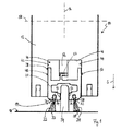
- a door leaf 10 of a sliding door is shown, wherein the door leaf 10 comprises a door leaf 12 and a seal 14.
- the door leaf 12 has a planar design and defines a door leaf plane 16 which is substantially perpendicular to a substantially horizontally arranged bottom surface 18.
- the door leaf 10 is mounted to open and close the sliding door in the horizontal direction in the door leaf plane 16 slidably to the bottom surface 18.
- the seal 14 includes a seal carrier member 20 to which a first seal member 22 and a second seal member 24 are attached.
- a seal carrier member 20 For attachment of the sealing elements 22, 24 on the seal carrier part 20, two grooves 26, 28 are formed on the seal carrier part 20 along its main extension direction, ie in the opening and closing direction of the sliding door, each having an undercut 30, 32.
- the first sealing element 22 has a complementary to the first groove 26 head portion 34 and the second seal member 24 has analogous to a complementary to the second groove 28 head portion 36. Due to the cross-sectional shapes of the grooves 26, 28 and the head parts 34, 36, the sealing elements 22, 24 are positively inserted into the seal carrier part 20. In this case, a median plane 33, 35 of the sealing elements 22, 24 is at an acute angle to the door leaf plane 16.
- the seal carrier part 20 is free in the direction of gravity S, ie substantially without a counterforce acting on the seal carrier part 20 during movement in the direction of the force of gravity S, slidingly mounted on the door leaf 12. So that the seal carrier part 20 can slide freely on the door leaf 12, the seal carrier part 20 has an outer contour 38, which corresponds to the shape of a groove-shaped recess 40 running in the opening and closing direction of the sliding door, also referred to as a door shoe.
- the cross section of the groove-shaped recess 40 is substantially rectangular.
- the groove has two flanks 42, 44 and a bottom 46 and is open towards the bottom surface 18.
- the seal carrier part 20 has two contact surfaces 48, 50 which are arranged at a distance from one another and whose spacing corresponds to the spacing of the flanks 42, 44. The seal carrier part 20 is thus movably guided in the vertical direction in the groove-shaped recess 40.
- a guide part 52 in the form of a guide groove is provided on the seal carrier part 20 into which a guide device 54 attached to the bottom surface 18 can engage in the form of a web.
- the guide groove 52 is only partially adapted to the width of the guide device 54 and formed wider at the other sections.
- the guide member 52 is disposed between the first seal member 22 and the second seal member 24, so that the seal members 22, 24 the Guide member 52 and the guide device 54 in the direction perpendicular to the door leaf level 16 surrounded by both sides.
- the guide part can also be designed as a web which engages in a guide device in the floor formed as a guide groove.
- a contact pressure of the sealing element required to produce a sealing effect on the bottom surface 18 is generated by the weight of the seal carrier part 20, which acts freely on the sealing elements 22, 24 and is supported by the sealing elements 22, 24.
- the sealing elements 22, 24 are arranged mirror-symmetrically to the longitudinal center plane of the seal carrier part 20 and are of a similar design in order to support torque-free half of the weight force applied by the seal carrier part 20 in each case.
- a spring element 56 between the door leaf 12 and the seal carrier member 20 is arranged and coupled to the door leaf 12 and a hook-shaped portion 57 of the seal carrier part 20.
- the spring element 56 which is designed as a leaf spring, provided with a bias, with which the spring element 56, the seal carrier member 20 is acted upon by a vertically acting spring force and thus the seal 14 presses against the bottom surface 18.
- the first sealing element 22 and the second sealing element 24 are in terms of their compressive and bending stiffness, so their modulus and their area moment of inertia, designed so that they can be supported against the bottom surface 18 of the acted upon by the spring force of the spring member 56 seal carrier member 20.
- the length of the groove-shaped recess is chosen slightly larger than the length of the seal carrier part 20.
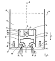
- Fig. 2 the door leaf 10 is shown in a transport state.
- the seal carrier part 20 is completely housed in the groove-shaped recess 40 and locked with a locking device 60.
- the locking device 60 comprises a cover plate 62, which is clipped with a plurality of clips 64 in openings 66 on the underside of the door panel 12.
- the cover plate 60 is used in addition to the locking of the seal 14 in the transport position to protect the seal 14 during transport.
- the locking device 60 can be solved, whereby the seal 14 can then move freely in the direction of gravity S until it abuts against the bottom surface 18. An adjustment of the height of the seal 14 is not necessary, since the contact pressure of the seal 14 automatically by the action of gravity - supported by the spring force of the spring element 56 - adjusts the seal carrier member 20.
Landscapes
- Engineering & Computer Science (AREA)
- Civil Engineering (AREA)
- Structural Engineering (AREA)
- Specific Sealing Or Ventilating Devices For Doors And Windows (AREA)
Abstract
Description
- Die vorliegende Erfindung betrifft einen Türflügel für eine Schiebetür, mit einem Türblatt und einer Dichtung. Die Dichtung umfasst ein Dichtungsträgerteil, welches vertikal verschiebbar an dem Türblatt gelagert ist, und zumindest ein von diesem getragenes Dichtungselement, welches in einem montierten Zustand des Türflügels mit einer Bodenfläche in Kontakt steht, wobei die Dichtung in einem Betriebszustand in Richtung der Schwerkraft frei gleitend an dem Türblatt gelagert ist und das Dichtungselement dazu ausgebildet ist, die Dichtung an der Bodenfläche abzustützen.
- Derartige Dichtungen dienen dazu, einen dichtenden Kontakt zwischen dem Türflügel und dem Boden an einer Unterseite eines Türblatts zu erzeugen. Ein solcher dichtender Kontakt zwischen dem Türflügel und dem Boden ist bei geschlossener Tür gewünscht, um beispielsweise einen Temperaturunterschied zweier Räume, die durch die geschlossene Tür voneinander getrennt sind, beizubehalten. Ferner sind solche Dichtungen dazu gedacht, den Eintritt von Staub in einen von dem Türflügel verschlossenen Raum zu verhindern, .
- Aus dem Stand der Technik sind Dichtungen mit einem Dichtungsträgerteil und einem Dichtungselement bekannt, welche fest, d.h. beispielsweise verschraubt oder mittels einer Rastverbindung, in einem unteren Bereich des Türblatts an diesem angebracht sind.
- Bekannte Dichtungen haben den Nachteil, dass sie für eine optimale Dichtwirkung an die Höhe eines von ihnen abgedichteten Schlitzes zwischen dem Türblatt und dem Boden angepasst werden müssen. Eine solche Anpassung, die in aller Regel durch Raststellungen der Dichtung in verschiedenen Höhen ermöglicht ist, ist aufwendig und kostet Zeit bei der Installation der Tür. Senkt sich die Tür über die Jahre ab, so erhöht sich der Anpressdruck der Dichtung auf den Boden. Hierdurch wird mehr Kraft benötigt, um die Tür zu öffnen, weshalb zum leichtgängigen Öffnen und Schließen der Tür eine erneute Anpassung der Dichtung notwendig wird.
- Aus der
DE 295 08 535 U1 , derDE 1 941 836 U und derDE 1 984 267 U ist eine Abdichtung zwischen der Unterseite einer Tür und dem Bodenbereich bekannt, welche eine Dichtleiste umfasst, die unter ihrer Schwerkraft selbsttätig höhenverschieblich in einer Ausnehmung am unteren Bereich der Tür liegt. Ein Führungsteil zur Führung des Türblatts einer Schiebetür ist hier nicht vorgesehen, welches zwischen zwei Dichtungselementen liegt und gemeinsam mit diesen die Dichtung bildet. - Aufgabe der vorliegenden Erfindung ist es, einen Türflügel mit einer Dichtung bereitzustellen, durch den die zuvor beschriebenen Nachteile beseitigt werden und somit eine Einstellung der Dichtung zur Anpassung an den von ihr abzudichtenden Schlitz sowie eine Überprüfung der Dichtwirkung und ein darauffolgendes Verstellen der Dichtung nicht mehr benötigt werden.
- Die Aufgabe wird gelöst durch einen Türflügel mit den Merkmalen des Anspruchs 1.
- Mit anderen Worten basiert die Erfindung auf der Idee, die Dichtung nicht an dem Türblatt zu fixieren, sondern stattdessen die Dichtung frei beweglich an dem Türblatt zu lagern und eine für die Dichtwirkung benötigte Anpresskraft dadurch zu erzeugen, dass die Erdanziehungskraft die Dichtung auf den Boden drückt.
- Eine besonders gute Dichtwirkung kann erzielt werden, wenn zwei Dichtungselemente, senkrecht zur Türblattebene gesehen, hintereinander vorgesehen sind. Mit anderen Worten sind die zwei Dichtungselemente entlang einer Richtungsachse versetzt zueinander angeordnet, welche senkrecht auf der Türblattebene steht. Die beiden Dichtungselemente sind von einem gemeinsamen Dichtungsträgerteil getragen.
- Da es sich bei dem Türflügel um einen Türflügel einer Schiebetür handelt, ist die Dichtung zumindest abschnittsweise mit einem Führungsteil versehen sein, welches zur Führung des Türblatts der Schiebetür in Verschieberichtung der Schiebetür längs einer am Boden vorgesehenen Führungseinrichtung ausgebildet ist. Dabei dient die Dichtung folglich - neben ihrer Dichtfunktion - zugleich auch zur Führung der Schiebetür an einer am Boden vorgesehenen Führungseinrichtung. Ein separates Führungsteil kann dadurch eingespart werden.
- Das Führungsteil ist an dem Dichtungsträgerteil ausgebildet. Das Dichtungsträgerteil kann im Vergleich zu dem Dichtungselement steifer ausgebildet sein, um eine definierte Führung des Türblatts zu gewährleisten.
- Der Führungsteil ist dabei senkrecht zur Türblattebene gesehen, zwischen zwei Dichtungselementen angeordnet.
- Vorteilhafte Ausbildungen der Erfindung sind den Unteransprüchen, der Beschreibung und den Zeichnungen zu entnehmen.
- Gemäß einer Ausführungsform weist das Türblatt an seiner dem Boden zugewandten Seite eine nutförmige Aussparung - einen sogenannten Türschuh - auf. Die nutförmige Aussparung erstreckt sich längs der Unterseite des Türblatts. Korrespondierend dazu weist das Dichtungsträgerteil eine Außenkontur auf, die mit der nutförmigen Aussparung zusammenwirkt, um eine Führung des Dichtungsträgerteils in vertikaler Richtung zu bilden. Beispielsweise kann die Außenkontur des Dichtungsträgerteils zwei zueinander parallele ebene Anlageflächen umfassen, die flächig an parallel zu den Anlageflächen angeordneten Flanken der nutförmigen Aussparung anliegen.
- Des Weiteren kann das Dichtungsträgerteil mindestens eine Nut aufweisen, in die ein Dichtungselement kraftschlüssig eingebracht ist. Zum formschlüssigen Einbringen des Dichtungselements in die Nut kann die Nut eine Hinterschneidung aufweisen. Hierdurch ist das Dichtungselement besonders verliersicher in der Nut gehalten.
- Gemäß einer weiteren Ausführungsform ist zwischen das Türblatt und das Dichtungsträgerteil mindestens ein Federelement eingesetzt, welches das Dichtungsträgerteil in Richtung der Schwerkraft mit einer Zusatzkraft, also einer zusätzlichen Anpresskraft, beaufschlagt. Der Einsatz eines solchen Federelements ist besonders dann vorteilhaft, wenn der durch die Schwerkraft erzeugte Anpressdruck der Dichtung auf den Boden nicht ausreichend ist.
- Gemäß einer besonders einfach herzustellenden Ausführungsform ist das Federelement als Blattfeder ausgebildet.
- Das Federelement kann mit dem Türblatt und dem Dichtungsträgerteil gekoppelt sein, um eine horizontale Verschiebung des Dichtungsträgerteils in Türblattebene relativ zu dem Türblatt zu begrenzen oder zu verhindern. Beispielsweise kann durch eine Kopplung des Türblatts mit dem Dichtungsträgerteil durch das Federelement auf einfache Weise bewirkt werden, dass bei einem Öffnen der Schiebetür das Dichtungsträgerteil an der Schiebetür gehalten und nicht durch Reibung der Dichtung am Boden eine relative Verschiebung zwischen Türblatt und Dichtung verursacht wird.
- Gemäß einer besonders einfach herzustellenden Ausführungsform ist das Dichtungsträgerteil zumindest abschnittsweise als Profil ausgebildet.
- Das Dichtungsträgerteil kann zumindest zum Teil aus Kunststoff und/oder einer Aluminiumlegierung bestehen. Kunststoff hat dabei den Vorteil, dass ein daraus bestehendes Dichtungsträgerteil kostengünstig herstellbar ist und ein geringes Gewicht aufweisen kann.
- Um den Transport des hergestellten Türflügels an den Einbauort zu vereinfachen und mögliche Schäden an der Dichtung durch den Transport zu vermeiden, kann eine Arretiervorrichtung vorgesehen sein, mit der die Dichtung in einer in das Türblatt eingefahrenen Position an dem Türblatt arretierbar ist. Die Arretiervorrichtung kann beispielsweise einen Stift, eine Schraube oder einen Clips umfassen. Die Arretiervorrichtung umfasst ferner bevorzugt eine Abdeckung, mit der die Dichtung zumindest teilweise abgedeckt transportierbar ist. Die Arretiervorrichtung kann fest oder lösbar an der Unterseite des Türblatts befestigt sein.
- Damit die Dichtung geschützt transportiert werden kann, ist es vorteilhaft, wenn die Tiefe der nutförmigen Aussparung an dem Türblatt wenigstens der Höhe des Dichtungsträgerteils entspricht.
- Das zumindest eine Dichtungselement ist bevorzugt zur Türblattebene geneigt an dem Dichtungsträgerteil angeordnet. Bei zwei Dichtungselementen stehen die Dichtungselemente bevorzugt jeweils nach außen ab, d.h. die Dichtungselemente sind mit ihrem dem Boden zugewandten Ende von einer Türblatthauptebene weg orientiert angeordnet.
- Gemäß einer bevorzugten Ausführungsform sind die zwei Dichtungselemente spiegelsymmetrisch zur Mittelachse des Dichtungsträgerteils angeordnet, um momentenfrei das Dichtungsträgerteil abzustützen.
- Das zumindest eine Dichtungselement kann bevorzugt als Bürste ausgebildet sein.
- Damit sich die Dichtung automatisch an Bodenunebenheiten in der Türblattebene anpasst, kann die Länge der nutförmigen Aussparung zumindest geringfügig größer sein als die Länge des Dichtungsträgerteils. Hierdurch kann auf einfache Weise ein Verkippen der Dichtung um eine senkrecht zur Türblattebene verlaufende Kippachse ermöglicht werden, damit sich die Dichtung selbstständig an ein Gefälle des Bodens in Haupterstreckungsrichtung der Dichtung, also im Wesentlichen horizontal in Türblattebene, anpassen kann.
- Nachfolgend wird die Erfindung anhand einer rein beispielhaften Ausführungsform unter Bezugnahme auf die beigefügten Zeichnungen beschrieben. Es zeigen:
- Fig. 1
- eine Schnittdarstellung eines erfindungsgemäßen Türflügels mit im Betriebszustand befindlicher Dichtung; und
- Fig. 2
- eine Schnittdarstellung des Türflügels mit einer in eingefahrener Position befindlichen Dichtung.
- In den Figuren ist ein Türflügel 10 einer Schiebetür gezeigt, wobei der Türflügel 10 ein Türblatt 12 und eine Dichtung 14 umfasst. Das Türblatt 12 ist flächig ausgebildet und definiert eine Türblattebene 16, welche im Wesentlichen senkrecht zu einer im Wesentlichen horizontal angeordneten Bodenfläche 18 steht. Der Türflügel 10 ist zum Öffnen und Schließen der Schiebetür in horizontaler Richtung in der Türblattebene 16 verschiebbar zur Bodenfläche 18 gelagert.
- Die Dichtung 14 umfasst ein Dichtungsträgerteil 20, an dem ein erstes Dichtungselement 22 und ein zweites Dichtungselement 24 angebracht sind. Zur Anbringung der Dichtungselemente 22, 24 an dem Dichtungsträgerteil 20 sind an dem Dichtungsträgerteil 20 entlang seiner Haupterstreckungsrichtung, also in Öffnungs- und Schließrichtung der Schiebetür, zwei Nuten 26, 28 ausgebildet, die jeweils eine Hinterschneidung 30, 32 aufweisen. Das erste Dichtungselement 22 weist einen zu der ersten Nut 26 komplementären Kopfteil 34 auf und das zweite Dichtungselement 24 weist analog dazu einen zu der zweiten Nut 28 komplementären Kopfteil 36 auf. Durch die Querschnittsformen der Nuten 26, 28 und der Kopfteile 34, 36 sind die Dichtungselemente 22, 24 formschlüssig in das Dichtungsträgerteil 20 eingebracht. Dabei steht eine Mittelebene 33, 35 der Dichtungselemente 22, 24 in einem spitzen Winkel zur Türblattebene 16.
- Das Dichtungsträgerteil 20 ist in Richtung der Schwerkraft S frei, also im Wesentlichen ohne dass bei einer Bewegung in Richtung der Schwerkraft S eine Gegenkraft auf das Dichtungsträgerteil 20 wirkt, gleitend an dem Türblatt 12 gelagert. Damit das Dichtungsträgerteil 20 frei an dem Türblatt 12 gleiten kann, weist das Dichtungsträgerteil 20 eine Außenkontur 38 auf, die mit der Form einer in Öffnungs- und Schließrichtung der Schiebetür verlaufenden, auch als Türschuh bezeichneten, nutförmigen Aussparung 40 korrespondiert. Der Querschnitt der nutförmigen Aussparung 40 ist dabei im Wesentlichen rechteckig. Die Nut weist zwei Flanken 42, 44 und einen Boden 46 auf und ist in Richtung auf die Bodenfläche 18 offen. Das Dichtungsträgerteil 20 weist zwei in einem Abstand zueinander angeordnete Anlageflächen 48, 50 auf, deren Abstand dem Abstand der Flanken 42, 44 entspricht. Das Dichtungsträgerteil 20 ist somit in vertikaler Richtung beweglich geführt in der nutförmigen Aussparung 40 aufgenommen.
- Zur Führung der Schiebetür entlang ihrer Öffnungs- und Schließrichtung ist an dem Dichtungsträgerteil 20 ein Führungsteil 52 in Form einer Führungsnut vorgesehen, in die eine an der Bodenfläche 18 angebrachte Führungseinrichtung 54 in Form eines Steges eingreifen kann. Um Material und Gewicht einzusparen, ist die Führungsnut 52 nur abschnittsweise der Breite der Führungseinrichtung 54 angepasst und an den anderen Abschnitten breiter ausgebildet.
- Der Führungsteil 52 ist zwischen dem ersten Dichtungselement 22 und dem zweiten Dichtungselement 24 angeordnet, sodass die Dichtungselemente 22, 24 den Führungsteil 52 und die Führungseinrichtung 54 in Richtung senkrecht zur Türblattebene 16 von beiden Seiten umgeben. Der Führungsteil kann alternativ zu der gezeigten Ausführungsform auch als Steg ausgebildet sein, der in eine als Führungsnut ausgebildete Führungseinrichtung im Boden eingreift.
- Ein zur Erzeugung einer Dichtwirkung benötigter Anpressdruck des Dichtungselementes an die Bodenfläche 18 wird durch die Gewichtskraft des Dichtungsträgerteils 20 erzeugt, welche frei auf die Dichtungselemente 22, 24 wirkt und von den Dichtungselementen 22, 24 abgestützt wird. Die Dichtungselemente 22, 24 sind spiegelsymmetrisch zur Längsmittelebene des Dichtungsträgerteils 20 angeordnet und gleichartig ausgebildet, um jeweils die Hälfte der von dem Dichtungsträgerteil 20 aufgebrachten Gewichtskraft momentenfrei abzustützen.
- Zur Unterstützung des Anpressdrucks, der sonst - wie zuvor beschrieben - lediglich durch das Eigengewicht der Dichtung 14 erzeugt wird, ist ein Federelement 56 zwischen dem Türblatt 12 und dem Dichtungsträgerteil 20 angeordnet und mit dem Türblatt 12 und einem hakenförmigen Abschnitt 57 des Dichtungsträgerteils 20 gekoppelt. In dem in
Fig. 1 gezeigten Betriebszustand der Dichtung 14 ist das Federelement 56, welches als Blattfeder ausgebildet ist, mit einer Vorspannung versehen, mit der das Federelement 56 das Dichtungsträgerteil 20 mit einer vertikal angreifenden Federkraft beaufschlagt und somit die Dichtung 14 gegen die Bodenfläche 18 drückt. Das erste Dichtungselement 22 und das zweite Dichtungselement 24 sind dabei bezüglich ihrer Druck- und Biegesteifigkeit, also ihres E-Moduls und ihres Flächenträgheitsmoments, so ausgebildet, dass sie das mit der Federkraft des Federelements 56 beaufschlagte Dichtungsträgerteil 20 gegen die Bodenfläche 18 abstützen können. - Die Länge der nutförmigen Aussparung, also das Maß in Öffnungs- bzw. Schließrichtung der Schiebetür, ist geringfügig größer gewählt als die Länge des Dichtungsträgerteils 20. Hierdurch ist ein Verkippen der Dichtung 14 um eine senkrecht zur Türblattebene 16 verlaufende Kippachse 58 möglich, um die Winkelstellung der Dichtung 14 einer Steigung der Bodenfläche 18 in der Öffnungs- bzw. Schließrichtung der Schiebetür anzupassen. Das heißt, die Dichtung 14 kann in einem Endbereich der nutförmigen Aussparung 40 tiefer eingefahren sein als in einem anderen Endbereich der nutförmigen Aussparung 40.
- In
Fig. 2 ist der Türflügel 10 in einem Transportzustand gezeigt. Hierzu ist das Dichtungsträgerteil 20 vollständig in der nutförmigen Aussparung 40 untergebracht und mit einer Arretiervorrichtung 60 arretiert. Die Arretiervorrichtung 60 umfasst eine Abdeckplatte 62, die mit mehreren Clips 64 in Öffnungen 66 an der Unterseite des Türblatts 12 einclipsbar ist. Die Abdeckplatte 60 dient neben der Arretierung der Dichtung 14 in der Transportposition zum Schutz der Dichtung 14 während des Transports. Zur Inbetriebnahme der Dichtung 14 in der Einbaulage kann die Arretiervorrichtung 60 gelöst werden, wodurch sich die Dichtung 14 dann frei in Richtung der Schwerkraft S bewegen kann, bis sie gegen die Bodenfläche 18 stößt. Eine Einstellung der Höhe der Dichtung 14 ist nicht nötig, da sich der Anpressdruck der Dichtung 14 automatisch durch das Wirken der Schwerkraft - unterstützt von der Federkraft des Federelements 56 - auf das Dichtungsträgerteil 20 einstellt. -
- 10
- Türflügel
- 12
- Türblatt
- 14
- Dichtung
- 16
- Türblattebene
- 18
- Bodenfläche
- 20
- Dichtungsträgerteil
- 22, 24
- Dichtungselement
- 26, 28
- Nut
- 30, 32
- Hinterschneidung
- 33, 35
- Mittelebene
- 34, 36
- Kopfteil
- 38
- Außenkontur
- 40
- nutförmige Aussparung
- 42, 44
- Flanke
- 46
- Boden
- 48, 50
- Anlagefläche
- 52
- Führungsteil
- 54
- Führungseinrichtung
- 56
- Federelement
- 57
- hakenförmiger Abschnitt
- 58
- Kippachse
- 60
- Arretiervorrichtung
- 62
- Abdeckplatte
- 64
- Clips
- 66
- Öffnungen
Claims (12)
- Türflügel (10) für eine Schiebetür, umfassend
ein Türblatt (12) und eine Dichtung (14) mit einem Dichtungsträgerteil (20), welches vertikal verschiebbar an dem Türblatt (12) gelagert ist, und zumindest einem von diesem getragenen Dichtungselement (22, 24), welches in einem montierten Zustand des Türflügels (10) mit einer Bodenfläche (18) in Kontakt steht, wobei die Dichtung (14) in einem Betriebszustand in Richtung der Schwerkraft (S) frei gleitend an dem Türblatt (12) gelagert ist und das Dichtungselement (22, 24) dazu ausgebildet ist, die Dichtung (14) an der Bodenfläche (18) abzustützen,
dadurch gekennzeichnet,
dass zwei Dichtungselemente (22, 24), senkrecht zur Türblattebene (16) gesehen, hintereinander vorgesehen sind, und die beiden Dichtungselemente (22, 24) von einem gemeinsamen Dichtungsträgerteil (20) getragen sind, und die Dichtung (14) zumindest abschnittsweise mit einem Führungsteil (52) versehen ist, welches zur Führung des Türblatts (12) einer Schiebetür in Verschieberichtung der Schiebetür längs einer am Boden vorgesehenen Führungseinrichtung ausgebildet ist und an dem Dichtungsträgerteil (20) ausgebildet ist, wobei der Führungsteil (52), senkrecht zur Türblattebene (16) gesehen, zwischen zwei Dichtungselementen (22, 24) angeordnet ist. - Türflügel (10) nach Anspruch 1,
dadurch gekennzeichnet,dass
das Türblatt (12) an seiner dem Boden zugewandten Seite eine nutförmige Aussparung (40) aufweist, welche sich längs der Unterseite des Türblatts (12) erstreckt, und dass das Dichtungsträgerteil (20) eine Außenkontur (38) aufweist, die mit der nutförmigen Aussparung (40) zusammenwirkt, um eine Führung des Dichtungsträgerteils (20) in vertikaler Richtung zu bilden. - Türflügel (10) nach Anspruch 1 oder 2,
dadurch gekennzeichnet,dass
das Dichtungsträgerteil (20) mindestens eine Nut (26, 28) aufweist, in die ein Dichtungselement (22, 24) kraftschlüssig eingebracht ist. - Türflügel (10) nach zumindest einem der vorstehenden Ansprüche,
dadurch gekennzeichnet,dass
zwischen das Türblatt (12) und das Dichtungsträgerteil (20) mindestens ein Federelement (56) eingesetzt ist, welches das Dichtungsträgerteil (20) in Richtung der Schwerkraft (S) mit einer Zusatzkraft beaufschlagt. - Türflügel (10) nach Anspruch 4,
dadurch gekennzeichnet,dass das Federelement (56) als Blattfeder ausgebildet ist. - Türflügel (10) nach Anspruch 4 oder 5,
dadurch gekennzeichnet,dass
das Federelement (56) mit dem Türblatt (12) und dem Dichtungsträgerteil (20) gekoppelt ist, um eine horizontale Verschiebung des Dichtungsträgerteils (20) in Türblattebene (16) relativ zu dem Türblatt (12) zu begrenzen oder zu verhindern. - Türflügel (10) nach zumindest einem der vorstehenden Ansprüche,
dadurch gekennzeichnet,dass
das Dichtungsträgerteil (20) als Profil ausgebildet ist. - Türflügel (10) nach zumindest einem der vorstehenden Ansprüche,
dadurch gekennzeichnet,dass
das Dichtungsträgerteil (20) zumindest zum Teil aus Kunststoff und/oder einer Aluminiumlegierung besteht. - Türflügel (10) nach zumindest einem der vorstehenden Ansprüche,
dadurch gekennzeichnet,dass
eine Arretiervorrichtung (60) vorgesehen ist, mit der die Dichtung (14) zu Transportzwecken in einer in das Türblatt (12) eingefahrenen Position an dem Türblatt (12) arretierbar ist. - Türflügel (10) nach zumindest einem der vorstehenden Ansprüche,
dadurch gekennzeichnet,dass
das zumindest eine Dichtungselement (22, 24) zur Türblattebene (16) geneigt an dem Dichtungsträgerteil (20) angeordnet ist. - Türflügel (10) nach zumindest einem der vorstehenden Ansprüche,
dadurch gekennzeichnet,dass
das zumindest eine Dichtungselement (22, 24) als Bürste ausgebildet ist. - Türflügel (10) nach zumindest einem der Ansprüche 1 bis 10,
dadurch gekennzeichnet,dass
das die Länge der nutförmigen Aussparung (40) zumindest geringfügig größer ist als die Länge des Dichtungsträgerteils (20), sodass ein Verkippen der Dichtung (14) um eine senkrecht zur Türblattebene verlaufende Kippachse (58) ermöglicht ist.
Priority Applications (1)
| Application Number | Priority Date | Filing Date | Title |
|---|---|---|---|
| PL16190086T PL3153653T3 (pl) | 2015-09-29 | 2016-09-22 | Skrzydło drzwiowe z uszczelką |
Applications Claiming Priority (1)
| Application Number | Priority Date | Filing Date | Title |
|---|---|---|---|
| DE102015218716.0A DE102015218716A1 (de) | 2015-09-29 | 2015-09-29 | Türflügel mit Dichtung |
Publications (2)
| Publication Number | Publication Date |
|---|---|
| EP3153653A1 true EP3153653A1 (de) | 2017-04-12 |
| EP3153653B1 EP3153653B1 (de) | 2018-03-28 |
Family
ID=56990281
Family Applications (1)
| Application Number | Title | Priority Date | Filing Date |
|---|---|---|---|
| EP16190086.5A Active EP3153653B1 (de) | 2015-09-29 | 2016-09-22 | Türflügel mit dichtung |
Country Status (5)
| Country | Link |
|---|---|
| EP (1) | EP3153653B1 (de) |
| CN (1) | CN106555542B (de) |
| DE (1) | DE102015218716A1 (de) |
| ES (1) | ES2672969T3 (de) |
| PL (1) | PL3153653T3 (de) |
Families Citing this family (1)
| Publication number | Priority date | Publication date | Assignee | Title |
|---|---|---|---|---|
| US11549306B2 (en) * | 2021-03-02 | 2023-01-10 | Global Material Technologies, Incorporated | Entryway seal suitable for attachment to breakout side panel of sliding door |
Citations (4)
| Publication number | Priority date | Publication date | Assignee | Title |
|---|---|---|---|---|
| DE1941836U (de) | 1966-04-05 | 1966-07-07 | Athmer Fa F | Tuerdichtung fuer den unteren tuerspalt. |
| DE1984267U (de) | 1967-10-17 | 1968-04-25 | Gottfried Eisenmenger | Bodenabdichtungsvorrichtung fuer schwellenlose tueren. |
| DE29508535U1 (de) | 1995-05-23 | 1995-08-10 | Brenk, Rainer, 59379 Selm | Vorrichtung zum Abdichten des Spaltes zwischen der Unterseite einer Tür und dem darunter befindlichen Bodenbereich |
| EP1746240A1 (de) * | 2005-07-18 | 2007-01-24 | SYLID Systemlogistik und Industriedienstleistung GmbH | Dichtungseinrichtung für den unteren Rand einer Tür |
Family Cites Families (3)
| Publication number | Priority date | Publication date | Assignee | Title |
|---|---|---|---|---|
| CN202227916U (zh) * | 2011-03-29 | 2012-05-23 | 刘端武 | 无障碍推拉门 |
| CN103867085A (zh) * | 2014-03-11 | 2014-06-18 | 江苏海陆科技股份有限公司 | 无障碍高隔声船用防火门升降密闭装置 |
| CN204238808U (zh) * | 2014-12-03 | 2015-04-01 | 铭铉(江西)医疗净化科技有限公司 | 一种平开门按压式底部密封结构 |
-
2015
- 2015-09-29 DE DE102015218716.0A patent/DE102015218716A1/de not_active Withdrawn
-
2016
- 2016-09-22 EP EP16190086.5A patent/EP3153653B1/de active Active
- 2016-09-22 PL PL16190086T patent/PL3153653T3/pl unknown
- 2016-09-22 ES ES16190086.5T patent/ES2672969T3/es active Active
- 2016-09-29 CN CN201611095463.6A patent/CN106555542B/zh active Active
Patent Citations (4)
| Publication number | Priority date | Publication date | Assignee | Title |
|---|---|---|---|---|
| DE1941836U (de) | 1966-04-05 | 1966-07-07 | Athmer Fa F | Tuerdichtung fuer den unteren tuerspalt. |
| DE1984267U (de) | 1967-10-17 | 1968-04-25 | Gottfried Eisenmenger | Bodenabdichtungsvorrichtung fuer schwellenlose tueren. |
| DE29508535U1 (de) | 1995-05-23 | 1995-08-10 | Brenk, Rainer, 59379 Selm | Vorrichtung zum Abdichten des Spaltes zwischen der Unterseite einer Tür und dem darunter befindlichen Bodenbereich |
| EP1746240A1 (de) * | 2005-07-18 | 2007-01-24 | SYLID Systemlogistik und Industriedienstleistung GmbH | Dichtungseinrichtung für den unteren Rand einer Tür |
Also Published As
| Publication number | Publication date |
|---|---|
| ES2672969T3 (es) | 2018-06-19 |
| PL3153653T3 (pl) | 2018-10-31 |
| CN106555542B (zh) | 2018-10-16 |
| EP3153653B1 (de) | 2018-03-28 |
| DE102015218716A1 (de) | 2017-03-30 |
| CN106555542A (zh) | 2017-04-05 |
Similar Documents
| Publication | Publication Date | Title |
|---|---|---|
| DE3789245T2 (de) | Gepäckträger. | |
| EP3153653B1 (de) | Türflügel mit dichtung | |
| DE202017007616U1 (de) | Möbel mit einem an einem Laufprofil verfahrbaren Schiebeelement und einer Führungseinrichtung | |
| AT507493B1 (de) | Laufrolle für einen schiebeflügel | |
| EP2792830A2 (de) | Halteelement zur Halterung eines Beschlagteils | |
| DE102008008696A1 (de) | Profil und Profilsystem | |
| EP2721983B1 (de) | Halteeinrichtung zur Montage an Duschstangen | |
| EP1486639B1 (de) | Absenkbare Türdichtung | |
| DE202012004752U1 (de) | Bodenführung für Glasschiebetüren | |
| DE102011000181B4 (de) | Einstellbarer Rollenhalter für Schiebetüren | |
| WO2005083217A1 (de) | Befestigunsvorrichtung für eine gleit- oder führungsschiene | |
| EP1873340B1 (de) | Türanlage | |
| DE102008006800B4 (de) | Führungsvorrichtung für einen Schiebeflügel | |
| DE102011053804A1 (de) | Wasserdichte Laufschiene für einen Schiebeflügel (Verfahren und Vorrichtung) | |
| DE19835684A1 (de) | Verfahrbare Türflügelanordnung | |
| DE4027512C1 (de) | ||
| DE102015122671A1 (de) | Beschlaganordnung mit rahmenseitigem Verstellelement | |
| EP3530861A1 (de) | Horizontalrahmenteil für einen schiebetür-und/oder schiebefensterrahmen, schiebetür- und/oder schiebefensterrahmen sowie schiebetür- und/oder schiebefenstersystem | |
| DE102019116881B3 (de) | Verbindungsadapter und Deckenverkleidungssystem | |
| EP1277910A1 (de) | Schwellenlose Türe mit absenkbarer Dichtung | |
| EP3674509B1 (de) | Abschlusselement | |
| DE2615682A1 (de) | Verriegelungsblende zur arretierung von elektronischen und elektromechanischen einschubbaugruppen | |
| DE202016008096U1 (de) | Gebäudeabschlussantriebsvorrichtung | |
| DE202011105571U1 (de) | Türschwellenkörper für eine Schiebetür | |
| EP3153891B1 (de) | Tor mit längenveränderbarem abstandshalter sowie ein verfahren zur montage dieses tores |
Legal Events
| Date | Code | Title | Description |
|---|---|---|---|
| PUAI | Public reference made under article 153(3) epc to a published international application that has entered the european phase |
Free format text: ORIGINAL CODE: 0009012 |
|
| AK | Designated contracting states |
Kind code of ref document: A1 Designated state(s): AL AT BE BG CH CY CZ DE DK EE ES FI FR GB GR HR HU IE IS IT LI LT LU LV MC MK MT NL NO PL PT RO RS SE SI SK SM TR |
|
| AX | Request for extension of the european patent |
Extension state: BA ME |
|
| 17P | Request for examination filed |
Effective date: 20170530 |
|
| RBV | Designated contracting states (corrected) |
Designated state(s): AL AT BE BG CH CY CZ DE DK EE ES FI FR GB GR HR HU IE IS IT LI LT LU LV MC MK MT NL NO PL PT RO RS SE SI SK SM TR |
|
| GRAP | Despatch of communication of intention to grant a patent |
Free format text: ORIGINAL CODE: EPIDOSNIGR1 |
|
| RIC1 | Information provided on ipc code assigned before grant |
Ipc: E06B 7/23 20060101ALI20171020BHEP Ipc: E06B 7/215 20060101AFI20171020BHEP Ipc: E06B 7/18 20060101ALI20171020BHEP Ipc: E06B 3/46 20060101ALI20171020BHEP |
|
| INTG | Intention to grant announced |
Effective date: 20171114 |
|
| GRAS | Grant fee paid |
Free format text: ORIGINAL CODE: EPIDOSNIGR3 |
|
| GRAA | (expected) grant |
Free format text: ORIGINAL CODE: 0009210 |
|
| AK | Designated contracting states |
Kind code of ref document: B1 Designated state(s): AL AT BE BG CH CY CZ DE DK EE ES FI FR GB GR HR HU IE IS IT LI LT LU LV MC MK MT NL NO PL PT RO RS SE SI SK SM TR |
|
| REG | Reference to a national code |
Ref country code: GB Ref legal event code: FG4D Free format text: NOT ENGLISH |
|
| REG | Reference to a national code |
Ref country code: CH Ref legal event code: EP |
|
| REG | Reference to a national code |
Ref country code: AT Ref legal event code: REF Ref document number: 983609 Country of ref document: AT Kind code of ref document: T Effective date: 20180415 |
|
| REG | Reference to a national code |
Ref country code: IE Ref legal event code: FG4D Free format text: LANGUAGE OF EP DOCUMENT: GERMAN |
|
| REG | Reference to a national code |
Ref country code: DE Ref legal event code: R096 Ref document number: 502016000785 Country of ref document: DE |
|
| REG | Reference to a national code |
Ref country code: ES Ref legal event code: FG2A Ref document number: 2672969 Country of ref document: ES Kind code of ref document: T3 Effective date: 20180619 |
|
| REG | Reference to a national code |
Ref country code: NL Ref legal event code: FP |
|
| REG | Reference to a national code |
Ref country code: SE Ref legal event code: TRGR |
|
| PG25 | Lapsed in a contracting state [announced via postgrant information from national office to epo] |
Ref country code: HR Free format text: LAPSE BECAUSE OF FAILURE TO SUBMIT A TRANSLATION OF THE DESCRIPTION OR TO PAY THE FEE WITHIN THE PRESCRIBED TIME-LIMIT Effective date: 20180328 Ref country code: LT Free format text: LAPSE BECAUSE OF FAILURE TO SUBMIT A TRANSLATION OF THE DESCRIPTION OR TO PAY THE FEE WITHIN THE PRESCRIBED TIME-LIMIT Effective date: 20180328 |
|
| REG | Reference to a national code |
Ref country code: LT Ref legal event code: MG4D |
|
| REG | Reference to a national code |
Ref country code: NO Ref legal event code: T2 Effective date: 20180328 |
|
| PG25 | Lapsed in a contracting state [announced via postgrant information from national office to epo] |
Ref country code: LV Free format text: LAPSE BECAUSE OF FAILURE TO SUBMIT A TRANSLATION OF THE DESCRIPTION OR TO PAY THE FEE WITHIN THE PRESCRIBED TIME-LIMIT Effective date: 20180328 Ref country code: GR Free format text: LAPSE BECAUSE OF FAILURE TO SUBMIT A TRANSLATION OF THE DESCRIPTION OR TO PAY THE FEE WITHIN THE PRESCRIBED TIME-LIMIT Effective date: 20180629 Ref country code: RS Free format text: LAPSE BECAUSE OF FAILURE TO SUBMIT A TRANSLATION OF THE DESCRIPTION OR TO PAY THE FEE WITHIN THE PRESCRIBED TIME-LIMIT Effective date: 20180328 Ref country code: BG Free format text: LAPSE BECAUSE OF FAILURE TO SUBMIT A TRANSLATION OF THE DESCRIPTION OR TO PAY THE FEE WITHIN THE PRESCRIBED TIME-LIMIT Effective date: 20180628 |
|
| REG | Reference to a national code |
Ref country code: FR Ref legal event code: PLFP Year of fee payment: 3 |
|
| PG25 | Lapsed in a contracting state [announced via postgrant information from national office to epo] |
Ref country code: MT Free format text: LAPSE BECAUSE OF FAILURE TO SUBMIT A TRANSLATION OF THE DESCRIPTION OR TO PAY THE FEE WITHIN THE PRESCRIBED TIME-LIMIT Effective date: 20180328 |
|
| PG25 | Lapsed in a contracting state [announced via postgrant information from national office to epo] |
Ref country code: AL Free format text: LAPSE BECAUSE OF FAILURE TO SUBMIT A TRANSLATION OF THE DESCRIPTION OR TO PAY THE FEE WITHIN THE PRESCRIBED TIME-LIMIT Effective date: 20180328 Ref country code: EE Free format text: LAPSE BECAUSE OF FAILURE TO SUBMIT A TRANSLATION OF THE DESCRIPTION OR TO PAY THE FEE WITHIN THE PRESCRIBED TIME-LIMIT Effective date: 20180328 Ref country code: RO Free format text: LAPSE BECAUSE OF FAILURE TO SUBMIT A TRANSLATION OF THE DESCRIPTION OR TO PAY THE FEE WITHIN THE PRESCRIBED TIME-LIMIT Effective date: 20180328 |
|
| PG25 | Lapsed in a contracting state [announced via postgrant information from national office to epo] |
Ref country code: SM Free format text: LAPSE BECAUSE OF FAILURE TO SUBMIT A TRANSLATION OF THE DESCRIPTION OR TO PAY THE FEE WITHIN THE PRESCRIBED TIME-LIMIT Effective date: 20180328 Ref country code: CZ Free format text: LAPSE BECAUSE OF FAILURE TO SUBMIT A TRANSLATION OF THE DESCRIPTION OR TO PAY THE FEE WITHIN THE PRESCRIBED TIME-LIMIT Effective date: 20180328 Ref country code: SK Free format text: LAPSE BECAUSE OF FAILURE TO SUBMIT A TRANSLATION OF THE DESCRIPTION OR TO PAY THE FEE WITHIN THE PRESCRIBED TIME-LIMIT Effective date: 20180328 |
|
| PG25 | Lapsed in a contracting state [announced via postgrant information from national office to epo] |
Ref country code: PT Free format text: LAPSE BECAUSE OF FAILURE TO SUBMIT A TRANSLATION OF THE DESCRIPTION OR TO PAY THE FEE WITHIN THE PRESCRIBED TIME-LIMIT Effective date: 20180730 |
|
| REG | Reference to a national code |
Ref country code: DE Ref legal event code: R097 Ref document number: 502016000785 Country of ref document: DE |
|
| PG25 | Lapsed in a contracting state [announced via postgrant information from national office to epo] |
Ref country code: DK Free format text: LAPSE BECAUSE OF FAILURE TO SUBMIT A TRANSLATION OF THE DESCRIPTION OR TO PAY THE FEE WITHIN THE PRESCRIBED TIME-LIMIT Effective date: 20180328 |
|
| PLBE | No opposition filed within time limit |
Free format text: ORIGINAL CODE: 0009261 |
|
| STAA | Information on the status of an ep patent application or granted ep patent |
Free format text: STATUS: NO OPPOSITION FILED WITHIN TIME LIMIT |
|
| 26N | No opposition filed |
Effective date: 20190103 |
|
| PG25 | Lapsed in a contracting state [announced via postgrant information from national office to epo] |
Ref country code: MC Free format text: LAPSE BECAUSE OF FAILURE TO SUBMIT A TRANSLATION OF THE DESCRIPTION OR TO PAY THE FEE WITHIN THE PRESCRIBED TIME-LIMIT Effective date: 20180328 |
|
| PG25 | Lapsed in a contracting state [announced via postgrant information from national office to epo] |
Ref country code: SI Free format text: LAPSE BECAUSE OF FAILURE TO SUBMIT A TRANSLATION OF THE DESCRIPTION OR TO PAY THE FEE WITHIN THE PRESCRIBED TIME-LIMIT Effective date: 20180328 |
|
| REG | Reference to a national code |
Ref country code: IE Ref legal event code: MM4A |
|
| PG25 | Lapsed in a contracting state [announced via postgrant information from national office to epo] |
Ref country code: IE Free format text: LAPSE BECAUSE OF NON-PAYMENT OF DUE FEES Effective date: 20180922 |
|
| PG25 | Lapsed in a contracting state [announced via postgrant information from national office to epo] |
Ref country code: TR Free format text: LAPSE BECAUSE OF FAILURE TO SUBMIT A TRANSLATION OF THE DESCRIPTION OR TO PAY THE FEE WITHIN THE PRESCRIBED TIME-LIMIT Effective date: 20180328 |
|
| PG25 | Lapsed in a contracting state [announced via postgrant information from national office to epo] |
Ref country code: CY Free format text: LAPSE BECAUSE OF FAILURE TO SUBMIT A TRANSLATION OF THE DESCRIPTION OR TO PAY THE FEE WITHIN THE PRESCRIBED TIME-LIMIT Effective date: 20180328 Ref country code: MK Free format text: LAPSE BECAUSE OF NON-PAYMENT OF DUE FEES Effective date: 20180328 Ref country code: HU Free format text: LAPSE BECAUSE OF FAILURE TO SUBMIT A TRANSLATION OF THE DESCRIPTION OR TO PAY THE FEE WITHIN THE PRESCRIBED TIME-LIMIT; INVALID AB INITIO Effective date: 20160922 |
|
| PG25 | Lapsed in a contracting state [announced via postgrant information from national office to epo] |
Ref country code: IS Free format text: LAPSE BECAUSE OF FAILURE TO SUBMIT A TRANSLATION OF THE DESCRIPTION OR TO PAY THE FEE WITHIN THE PRESCRIBED TIME-LIMIT Effective date: 20180728 |
|
| P01 | Opt-out of the competence of the unified patent court (upc) registered |
Effective date: 20230510 |
|
| REG | Reference to a national code |
Ref country code: CH Ref legal event code: U11 Free format text: ST27 STATUS EVENT CODE: U-0-0-U10-U11 (AS PROVIDED BY THE NATIONAL OFFICE) Effective date: 20251001 |
|
| PGFP | Annual fee paid to national office [announced via postgrant information from national office to epo] |
Ref country code: FI Payment date: 20250929 Year of fee payment: 10 |
|
| PGFP | Annual fee paid to national office [announced via postgrant information from national office to epo] |
Ref country code: DE Payment date: 20250930 Year of fee payment: 10 |
|
| PGFP | Annual fee paid to national office [announced via postgrant information from national office to epo] |
Ref country code: NO Payment date: 20250923 Year of fee payment: 10 |
|
| PGFP | Annual fee paid to national office [announced via postgrant information from national office to epo] |
Ref country code: NL Payment date: 20250918 Year of fee payment: 10 Ref country code: LU Payment date: 20250919 Year of fee payment: 10 Ref country code: PL Payment date: 20250912 Year of fee payment: 10 Ref country code: IT Payment date: 20250923 Year of fee payment: 10 |
|
| PGFP | Annual fee paid to national office [announced via postgrant information from national office to epo] |
Ref country code: BE Payment date: 20250918 Year of fee payment: 10 Ref country code: GB Payment date: 20250919 Year of fee payment: 10 |
|
| PGFP | Annual fee paid to national office [announced via postgrant information from national office to epo] |
Ref country code: FR Payment date: 20250922 Year of fee payment: 10 Ref country code: AT Payment date: 20250919 Year of fee payment: 10 |
|
| PGFP | Annual fee paid to national office [announced via postgrant information from national office to epo] |
Ref country code: SE Payment date: 20250918 Year of fee payment: 10 |
|
| PGFP | Annual fee paid to national office [announced via postgrant information from national office to epo] |
Ref country code: CH Payment date: 20251001 Year of fee payment: 10 |
|
| PGFP | Annual fee paid to national office [announced via postgrant information from national office to epo] |
Ref country code: ES Payment date: 20251028 Year of fee payment: 10 |