EP3151256B1 - Rolled iron core traction transformer - Google Patents
Rolled iron core traction transformer Download PDFInfo
- Publication number
- EP3151256B1 EP3151256B1 EP15798885.8A EP15798885A EP3151256B1 EP 3151256 B1 EP3151256 B1 EP 3151256B1 EP 15798885 A EP15798885 A EP 15798885A EP 3151256 B1 EP3151256 B1 EP 3151256B1
- Authority
- EP
- European Patent Office
- Prior art keywords
- winding
- high voltage
- iron
- low voltage
- core
- Prior art date
- Legal status (The legal status is an assumption and is not a legal conclusion. Google has not performed a legal analysis and makes no representation as to the accuracy of the status listed.)
- Active
Links
Images



Classifications
-
- H—ELECTRICITY
- H01—ELECTRIC ELEMENTS
- H01F—MAGNETS; INDUCTANCES; TRANSFORMERS; SELECTION OF MATERIALS FOR THEIR MAGNETIC PROPERTIES
- H01F27/00—Details of transformers or inductances, in general
- H01F27/24—Magnetic cores
- H01F27/245—Magnetic cores made from sheets, e.g. grain-oriented
- H01F27/2455—Magnetic cores made from sheets, e.g. grain-oriented using bent laminations
-
- H—ELECTRICITY
- H01—ELECTRIC ELEMENTS
- H01F—MAGNETS; INDUCTANCES; TRANSFORMERS; SELECTION OF MATERIALS FOR THEIR MAGNETIC PROPERTIES
- H01F37/00—Fixed inductances not covered by group H01F17/00
- H01F37/005—Fixed inductances not covered by group H01F17/00 without magnetic core
-
- H—ELECTRICITY
- H01—ELECTRIC ELEMENTS
- H01F—MAGNETS; INDUCTANCES; TRANSFORMERS; SELECTION OF MATERIALS FOR THEIR MAGNETIC PROPERTIES
- H01F17/00—Fixed inductances of the signal type
- H01F17/02—Fixed inductances of the signal type without magnetic core
-
- H—ELECTRICITY
- H01—ELECTRIC ELEMENTS
- H01F—MAGNETS; INDUCTANCES; TRANSFORMERS; SELECTION OF MATERIALS FOR THEIR MAGNETIC PROPERTIES
- H01F27/00—Details of transformers or inductances, in general
- H01F27/08—Cooling; Ventilating
-
- H—ELECTRICITY
- H01—ELECTRIC ELEMENTS
- H01F—MAGNETS; INDUCTANCES; TRANSFORMERS; SELECTION OF MATERIALS FOR THEIR MAGNETIC PROPERTIES
- H01F27/00—Details of transformers or inductances, in general
- H01F27/28—Coils; Windings; Conductive connections
- H01F27/29—Terminals; Tapping arrangements for signal inductances
-
- H—ELECTRICITY
- H01—ELECTRIC ELEMENTS
- H01F—MAGNETS; INDUCTANCES; TRANSFORMERS; SELECTION OF MATERIALS FOR THEIR MAGNETIC PROPERTIES
- H01F29/00—Variable transformers or inductances not covered by group H01F21/00
-
- H—ELECTRICITY
- H01—ELECTRIC ELEMENTS
- H01F—MAGNETS; INDUCTANCES; TRANSFORMERS; SELECTION OF MATERIALS FOR THEIR MAGNETIC PROPERTIES
- H01F41/00—Apparatus or processes specially adapted for manufacturing or assembling magnets, inductances or transformers; Apparatus or processes specially adapted for manufacturing materials characterised by their magnetic properties
- H01F41/02—Apparatus or processes specially adapted for manufacturing or assembling magnets, inductances or transformers; Apparatus or processes specially adapted for manufacturing materials characterised by their magnetic properties for manufacturing cores, coils, or magnets
- H01F41/04—Apparatus or processes specially adapted for manufacturing or assembling magnets, inductances or transformers; Apparatus or processes specially adapted for manufacturing materials characterised by their magnetic properties for manufacturing cores, coils, or magnets for manufacturing coils
- H01F41/06—Coil winding
- H01F41/08—Winding conductors onto closed formers or cores, e.g. threading conductors through toroidal cores
Definitions
- This invention relates to a rolled iron core traction transformer.
- a traction transformer is commonly used as a power equipment in the field of electrified railways, which is characterized by long time of no-load operation (the traction transformer is almost at no- load in the train gaps period), high overload capacity, and more times of short-circuit.
- Conventional traction transformers use a laminated iron core, the inner and outer coils of which are sequentially fitted over the iron core.
- the laminated iron core is made of a laminated silicon steel.
- the air gap which has high value of magnetic reluctance, is formed in the butt joint of the silicon steel, so that no-load losses and no-load current are increased, and the noise is relatively larger.
- the process of cutting and stacking the silicon steel which also makes the no-load losses increasing, will affect the arrangement of magnetic domains.
- a gap should be reserved when loop coils are looped, however the gap would decrease the resistance of short-circuit of the coil.
- US 360 198 A1 discloses an induction coil or transformer consisting of a series or plurality of superposed or parallel rings or disks, each made of a coiled iron ribbon, and insulating material between the different layers of the ribbon, and two or more sets of copper conductors for the primary and secondary currents wound on the core formed by the series of rings or disks and having free terminals.
- the invention provides a rolled iron core traction transformer, which can reduce no-load loss, has a smaller no-load current, lower noise and enhance anti-short circuit, reduces the electrodynamic force generated by a sudden short circuit and improves the short circuit tolerance capability of the transformer.
- a rolled iron core traction transformer is defined by claim 1.
- the invention provides a rolled iron core traction transformer, comprising an iron core, wherein the iron core is formed by splicing two symmetrical annealed iron-core closed single frames, each iron-core closed single frame is formed by sequentially coiling continuous silicon steel sheets, the iron-core closed single frame having two iron-core column single bodies which cross sections are semicircular, the iron core having two iron-core columns, which cross sections are circular, thereon formed by splicing two iron-core column single bodies, wherein each iron-core column is sequentially provided with a low voltage T winding, a low voltage F winding and a high voltage winding thereon from inside to outside; wherein two sides of each high voltage winding are respectively provided with a first tapping area and a second tapping area, wherein the first tapping area is provided with low voltage side high voltage tapping outgoing lines, wherein the second tapping area is provided with high voltage side high voltage tapping outgoing lines, two low voltage side high voltage tapping outgoing lines are connected together with a no-load voltage
- a cooling separation trough is provided between two iron-core closed single frames for lower the iron-core temperature and enhance over-excitation.
- the said two no-load voltage regulation switches are connected by a switch linkage, which achieving synchronization voltage regulation, to make the two no-load voltage regulation switch can be synchronized.
- the both ends of the low voltage F winding and the high voltage winding are provided with electrostatic plates.
- the electrostatic plates are formed by welding two semi-circular brass rings.
- a T winding skeleton is provided inside of the low voltage T winding
- a stay with caging device is provided between the T winding skeleton and the iron-core column
- a F winding skeleton is provided inside of the low voltage F winding
- a stay with caging device is provided between the F winding skeleton and the T winding
- a high voltage winding skeleton is provided inside of the high voltage winding
- a stay with caging device is provided between the high voltage winding skeleton and the low voltage F winding .
- T winding skeleton and /or the F winding skeleton and /or the high voltage winding skeleton are/is made of hard paper tubes.
- a drive slot which can be driven by a winder, is provided in the T winding skeleton.
- the position, which should be set the stay 19 is provided with transmission mechanism of the special no mold winder, and then forming the T winding skeleton. Then wind the low voltage T winding, the low voltage F winding and the high voltage winding in turn.
- the stay is arranged between T winding skeleton and iron-core column to tight the coils.
- the iron-core closed single frames is wound by continuous silicon steel, without air gap in the middle, so that the overheating, high noise, large excitation current which may be caused by local high magnetic flux density will be avoided. And after annealing process, the stress in the iron core that generated in the process is eliminated, thus no load loss is reduced too.
- the windings use double parallel column, the high voltage winding of each column provide with two tapping area. The unbalanced ampere turns due to tapping area between high and low winding is reduced by four tapping area, thereby the electric power generated when the sudden short-circuit is reduced, and the withstanding short circuit capacity of the transformer is improved. All windings combine into one, with compact structure, enhanced mechanical strength, high resistance capability to short-circuit.
- a rolled iron core traction transformer comprises an iron core 1, which is spliced by two symmetrical annealed iron-core closed single frames 1-1, wherein each iron-core closed single frame 1-1 is formed by sequentially coiling continuous silicon steel sheets.
- the iron-core closed single frame 1-1 has two iron-core column single bodies 1-1-1, the sections of which are approximately semicircular.
- the iron core 1 has two iron-core columns 1-2, the sections of which are approximately circular, formed thereon by splicing the two iron-core column single bodies 1-1-1.
- Each iron-core column 1-2 is sequentially provided with a low voltage T winding 6, a low voltage F winding 5 and a high voltage winding 4 thereon from inside to outside; wherein two sides of each high voltage winding 4 are respectively provided with a first tapping area and a second tapping area, the first tapping area is provided with low voltage side high voltage tapping outgoing lines 16, and the second tapping area is provided with high voltage side high voltage tapping outgoing lines 18.
- Two low voltage side high voltage tapping outgoing lines 16 are connected together with a no-load voltage regulation switch 9, and two high voltage side high voltage tapping outgoing lines 18 are connected together with another no-load voltage regulation switch 9.
- the side of the high voltage winding 4 is provided with high voltage winding outgoing lines 17, low voltage T winding outgoing lines 15-1 of the low voltage T winding 6 is provided on one side of opposite direction of the high voltage winding outgoing lines 17 on the low voltage T winding 6.
- Low voltage F winding outgoing lines 15-2 of the low voltage F winding 5 is provided on one side of opposite of the high voltage winding outgoing lines 17 on the low voltage F winding 5.
- the iron-core closed single frames 1-1 is wound by continuous silicon steel, without air gap in the middle, in order to avoid overheating, noise, large excitation current caused by local high magnetic flux density, and eliminating the stress of the iron core after annealing process , further reducing no load loss.
- the winding uses double column parallel, the high voltage winding of each column sets two tap areas.
- Four tap areas reduce unbalanced ampere turns of due to tap area production between high and low winding, thereby the electric power generated when the sudden short-circuit is reduced, and the withstanding short circuit capacity of the transformer is improved.
- the iron core 1 is a closed rolled iron core, so all of the low voltage T winding 6, all of the low voltage F winding 5 and all of the high voltage winding 4 must be wound on the iron-core column 1-2 of the iron core 1.
- the low voltage T winding 6, the low voltage F winding 5 and the high voltage winding 4 are all around the iron-core column 1-2 into one in a special vertical mode free winder 3, which drives the forming skeleton 7 of coils to rotate. Wire winds around and rolls over the forming skeleton 7 to form a coil.
- the forming skeleton 7 is provided with a drive slot, into which the drive pin 8 of the vertical mode free winder 3 extends, to drive the forming skeleton 7 to rotate around the iron-core column1 2, to thus wind the low voltage T winding 6, the low voltage F winding 5 and the high voltage winding 4.
- Fig.5 and Fig.6 show a method of mode free vertical winding, which is the only way to achieve a wound pancake coil on a large rolled iron-core.
- a separation trough 2 for cooling is provided between two iron-core closed single frames 1-1, to thus lower the iron core temperature, enhance over-excitation and improve utilization of the silicon steel.
- One function of the separation trough 2 is heat radiation, and another is to divide the iron core into two approximately semicircular, to make the silicon steel easy to be cut completely even if the iron core diameter is larger.
- two no-load voltage regulation switches 9 are connected by a switch linkage 11 for synchronization voltage regulation.
- electrostatic plates 10 are provided on the both ends of the low voltage F winding 5 and the high voltage winding 4.
- the electrostatic plate 10 is formed by welding two semi-circular brass rings 10-1.
- the electrostatic plate 10 is placed in pairs, such as the electrostatic plates 10 are provided on the both ends of the low voltage F winding 5, adjacent to high voltage winding 4.
- the electrostatic plate 10 is formed by joining two semi-circular together, specifically, welding the surrounding rounded semicircle copper ring 10-1, which is spliced on the iron core 1, and the following smooth polishing.
- the electrostatic plate 10 of the high voltage winding 4 can be produced by the above method.
- the T winding skeleton 14 is provided inside the low voltage T winding 6
- the stay 19 with caging device is provided between the T winding skeleton 14 and the iron-core column 1-2
- the F winding skeleton 13 is provided inside of the low voltage F winding 5
- the stay 19 with caging device is provided between the F winding skeleton 13 and the T winding skeleton 6
- a high voltage winding skeleton 12 is provided inside the high voltage winding 4
- the stay 19 with caging device is provided between the high voltage winding skeleton 12 and the low voltage F winding 5.
- the T winding skeleton 14 and/or the F winding skeleton 13 and /or the high voltage winding skeleton12 are/is made of hard paper tubes.
- a drive slot, which can be driven by winders, is provided with the T winding skeleton 14. For all the stays between the windings having caging device, stay 19 will not be placed between T winding skeleton 14 and iron-core column 1-2 at first when wind windings, to prevent the stays shift while wind windings.
- the position, which should be set the stay 19, is provided with a transmission mechanism of the special no mold winder, and then the T winding skeleton 14 is formed on it. After that, the low voltage T winding 6, the low voltage winding F 5 and high voltage winding 4 are wound in turn. After all windings are wound, the stay 19 is put between T winding skeleton 14 and iron-core column 1-2 to tight the coils.
- the hard paper tube is spliced directly, as shown in Fig. 9 , the stay 19 adjacent to the lap of the hard paper tube of the low voltage F winding 5 is designed as the shape of the inner mold, after gluing in lapped ramp of the hard paper tube of the low pressure F winding 5 an outer mold 20 is used to press for forming, then the low voltage F winding 5 can be wound in the hard paper tube of the low voltage F winding 5.
- the same process can be used for the hard paper tube of the low voltage T winding 6 and the hard paper tube of the high voltage winding 4.
Landscapes
- Engineering & Computer Science (AREA)
- Power Engineering (AREA)
- Microelectronics & Electronic Packaging (AREA)
- Coils Of Transformers For General Uses (AREA)
Description
- This invention relates to a rolled iron core traction transformer.
- Currently, a traction transformer is commonly used as a power equipment in the field of electrified railways, which is characterized by long time of no-load operation (the traction transformer is almost at no- load in the train gaps period), high overload capacity, and more times of short-circuit. Conventional traction transformers use a laminated iron core, the inner and outer coils of which are sequentially fitted over the iron core. The laminated iron core is made of a laminated silicon steel. The air gap, which has high value of magnetic reluctance, is formed in the butt joint of the silicon steel, so that no-load losses and no-load current are increased, and the noise is relatively larger. The process of cutting and stacking the silicon steel, which also makes the no-load losses increasing, will affect the arrangement of magnetic domains. A gap should be reserved when loop coils are looped, however the gap would decrease the resistance of short-circuit of the coil.
-
US 360 198 A1 discloses an induction coil or transformer consisting of a series or plurality of superposed or parallel rings or disks, each made of a coiled iron ribbon, and insulating material between the different layers of the ribbon, and two or more sets of copper conductors for the primary and secondary currents wound on the core formed by the series of rings or disks and having free terminals. - Technical problems will be solved by the invention to overcome the defects of the prior art. The invention provides a rolled iron core traction transformer, which can reduce no-load loss, has a smaller no-load current, lower noise and enhance anti-short circuit, reduces the electrodynamic force generated by a sudden short circuit and improves the short circuit tolerance capability of the transformer.
- A rolled iron core traction transformer is defined by
claim 1. - In order to resolve the above mentioned technical problem, the invention provides a rolled iron core traction transformer, comprising an iron core, wherein the iron core is formed by splicing two symmetrical annealed iron-core closed single frames, each iron-core closed single frame is formed by sequentially coiling continuous silicon steel sheets, the iron-core closed single frame having two iron-core column single bodies which cross sections are semicircular, the iron core having two iron-core columns, which cross sections are circular, thereon formed by splicing two iron-core column single bodies, wherein each iron-core column is sequentially provided with a low voltage T winding, a low voltage F winding and a high voltage winding thereon from inside to outside; wherein two sides of each high voltage winding are respectively provided with a first tapping area and a second tapping area, wherein the first tapping area is provided with low voltage side high voltage tapping outgoing lines, wherein the second tapping area is provided with high voltage side high voltage tapping outgoing lines, two low voltage side high voltage tapping outgoing lines are connected together with a no-load voltage regulation switch, and two high voltage side high voltage tapping outgoing lines are connected together with another no-load voltage regulation switch, the side of the high voltage winding is provided with high voltage winding outgoing lines, the low voltage T winding is provided with low voltage T winding outgoing lines on one opposite direction side of the high voltage winding outgoing lines, the low voltage F winding is provided with low voltage F winding outgoing lines on one opposite direction side of the high voltage winding outgoing lines.
- Dependent claims relate to preferred embodiments.
- According to some preferred embodiments, a cooling separation trough is provided between two iron-core closed single frames for lower the iron-core temperature and enhance over-excitation.
- According to some preferred embodiments, the said two no-load voltage regulation switches are connected by a switch linkage, which achieving synchronization voltage regulation, to make the two no-load voltage regulation switch can be synchronized.
- According to some preferred embodiments, on the both ends of the low voltage F winding and the high voltage winding are provided with electrostatic plates.
- According to some preferred embodiments, the electrostatic plates are formed by welding two semi-circular brass rings.
- According to some preferred embodiments, a T winding skeleton is provided inside of the low voltage T winding, a stay with caging device is provided between the T winding skeleton and the iron-core column, a F winding skeleton is provided inside of the low voltage F winding, and a stay with caging device is provided between the F winding skeleton and the T winding, a high voltage winding skeleton is provided inside of the high voltage winding, and a stay with caging device is provided between the high voltage winding skeleton and the low voltage F winding .
- Further, the T winding skeleton and /or the F winding skeleton and /or the high voltage winding skeleton are/is made of hard paper tubes.
- Further, a drive slot, which can be driven by a winder, is provided in the T winding skeleton.
- According to some preferred embodiments, don't place stay between T winding skeleton and iron-core column first when wind windings. The position, which should be set the
stay 19, is provided with transmission mechanism of the special no mold winder, and then forming the T winding skeleton. Then wind the low voltage T winding, the low voltage F winding and the high voltage winding in turn. - Furthermore, after winding all the said windings, the stay is arranged between T winding skeleton and iron-core column to tight the coils.
- In the above-mentioned technical solution, the iron-core closed single frames is wound by continuous silicon steel, without air gap in the middle, so that the overheating, high noise, large excitation current which may be caused by local high magnetic flux density will be avoided. And after annealing process, the stress in the iron core that generated in the process is eliminated, thus no load loss is reduced too. The windings use double parallel column, the high voltage winding of each column provide with two tapping area. The unbalanced ampere turns due to tapping area between high and low winding is reduced by four tapping area, thereby the electric power generated when the sudden short-circuit is reduced, and the withstanding short circuit capacity of the transformer is improved. All windings combine into one, with compact structure, enhanced mechanical strength, high resistance capability to short-circuit.
-
-
Fig.1 is a section view of a rolled iron core traction transformer of the invention; -
Fig.2 is a top view of theFIG. 1 ; -
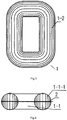
Fig.3 is a schematic diagram of the iron core of the invention; -
Fig.4 is cross-sectional view of the iron core of the invention; -
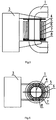
Fig.5 is a rolling schematic diagram of the winding of the invention; -
Fig.6 is a top view of theFIG. 5 ; -
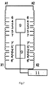
Fig.7 is a wiring schematic diagram of the high voltage winding of the invention; -
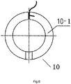
Fig. 8 is a installation schematic diagram of the electrostatic plate of the invention; -
Fig. 9 is a installation diagram of the skeleton of the invention. - In order to provide a better and clearer understanding of the invention, a detailed description with examples of embodiments of the invention will now be provided.
- As shown in
Fig.1-Fig.4 , a rolled iron core traction transformer comprises aniron core 1, which is spliced by two symmetrical annealed iron-core closed single frames 1-1, wherein each iron-core closed single frame 1-1 is formed by sequentially coiling continuous silicon steel sheets. The iron-core closed single frame 1-1 has two iron-core column single bodies 1-1-1, the sections of which are approximately semicircular. Theiron core 1 has two iron-core columns 1-2, the sections of which are approximately circular, formed thereon by splicing the two iron-core column single bodies 1-1-1. Each iron-core column 1-2 is sequentially provided with a low voltage T winding 6, a low voltage F winding 5 and a high voltage
winding 4 thereon from inside to outside; wherein two sides of each high voltage winding 4 are respectively provided with a first tapping area and a second tapping area, the first tapping area is provided with low voltage side high voltage tappingoutgoing lines 16, and the second tapping area is provided with high voltage side high voltage tappingoutgoing lines 18. Two low voltage side high voltage tappingoutgoing lines 16 are connected together with a no-loadvoltage regulation switch 9, and two high voltage side high voltage tappingoutgoing lines 18 are connected together with another no-loadvoltage regulation switch 9. The side of thehigh voltage winding 4 is provided with high voltage windingoutgoing lines 17, low voltage T winding outgoing lines 15-1 of the low voltage T winding 6 is provided on one side of opposite direction of the high voltage windingoutgoing lines 17 on the low voltage T winding 6. Low voltage F winding outgoing lines 15-2 of the low voltage F winding 5 is provided on one side of opposite of the high voltage windingoutgoing lines 17 on the low voltage F winding 5. The iron-core closed single frames 1-1 is wound by continuous silicon steel, without air gap in the middle, in order to avoid overheating, noise, large excitation current caused by local high magnetic flux density, and eliminating the stress of the iron core after annealing process , further reducing no load loss. The winding uses double column parallel, the high voltage winding of each column sets two tap areas. Four tap areas reduce unbalanced ampere turns of due to tap area production between high and low winding, thereby the electric power generated when the sudden short-circuit is reduced, and the withstanding short circuit capacity of the transformer is improved. - As shown in
Fig.5 and Fig.6 , since theiron core 1 is a closed rolled iron core, so all of the low voltage T winding 6, all of the low voltage F winding 5 and all of thehigh voltage winding 4 must be wound on the iron-core column 1-2 of theiron core 1. The low voltage T winding 6, the low voltage F winding 5 and the high voltage winding 4 are all around the
iron-core column 1-2 into one in a special vertical modefree winder 3, which drives the forming skeleton 7 of coils to rotate. Wire winds around and rolls over the forming skeleton 7 to form a coil. The forming skeleton 7 is provided with a drive slot, into which the drive pin 8 of the vertical modefree winder 3 extends, to drive the forming skeleton 7 to rotate around the iron-core column1 2, to thus wind the low voltage T winding 6, the low voltage F winding 5 and the high voltage winding 4.Fig.5 and Fig.6 show a method of mode free vertical winding, which is the only way to achieve a wound pancake coil on a large rolled iron-core. - As shown in
Fig. 4 , aseparation trough 2 for cooling is provided between two iron-core closed single frames 1-1, to thus lower the iron core temperature, enhance over-excitation and improve utilization of the silicon steel. One function of theseparation trough 2 is heat radiation, and another is to divide the iron core into two approximately semicircular, to make the silicon steel easy to be cut completely even if the iron core diameter is larger. - As shown in
Fig. 2 andFig.7 , two no-loadvoltage regulation switches 9 are connected by aswitch linkage 11 for synchronization voltage regulation. - As shown in
Fig. 1 ,electrostatic plates 10 are provided on the both ends of the low voltage F winding 5 and the high voltage winding 4. Theelectrostatic plate 10 is formed by welding two semi-circular brass rings 10-1. Theelectrostatic plate 10 is placed in pairs, such as theelectrostatic plates 10 are provided on the both ends of the low voltage F winding 5, adjacent to high voltage winding 4. As shown inFig. 8 . to be installed on theclosed iron core 1, theelectrostatic plate 10 is formed by joining two semi-circular together, specifically, welding the surrounding rounded semicircle copper ring 10-1, which is spliced on theiron core 1,
and the following smooth polishing. Theelectrostatic plate 10 of the high voltage winding 4 can be produced by the above method. - As shown in
Fig. 2 andFig.8 , theT winding skeleton 14 is provided inside the low voltage T winding 6, thestay 19 with caging device is provided between theT winding skeleton 14 and the iron-core column 1-2, theF winding skeleton 13 is provided inside of the low voltage F winding 5, also thestay 19 with caging device is provided between theF winding skeleton 13 and theT winding skeleton 6, a highvoltage winding skeleton 12 is provided inside the high voltage winding 4, also thestay 19 with caging device is provided between the highvoltage winding skeleton 12 and the low voltage F winding 5. TheT winding skeleton 14 and/or theF winding skeleton 13 and /or the high voltage winding skeleton12 are/is made of hard paper tubes. A drive slot, which can be driven by winders, is provided with theT winding skeleton 14. For all the stays between the windings having caging device, stay 19 will not be placed betweenT winding skeleton 14 and iron-core column 1-2 at first when wind windings, to prevent the stays shift while wind windings. - The position, which should be set the
stay 19, is provided with a transmission mechanism of the special no mold winder, and then theT winding skeleton 14 is formed on it. After that, the low voltage T winding 6, the lowvoltage winding F 5 and high voltage winding 4 are wound in turn. After all windings are wound, thestay 19 is put betweenT winding skeleton 14 and iron-core column 1-2 to tight the coils. - All coils using hard paper tube as a skeleton, the hard paper tube is spliced directly, as shown in
Fig. 9 , thestay 19 adjacent to the lap of the hard paper tube of the low voltage F winding 5 is designed as the shape of the inner mold, after gluing in lapped ramp of the hard paper tube of the low pressure F winding 5 anouter mold 20 is used to press for forming, then the low voltage F winding 5 can be wound in the hard paper tube of the low voltage F winding 5. The same process can be used for the hard paper tube of the low voltage T winding 6 and the hard paper tube of the high voltage winding 4. - Specific embodiments were described above, as further explanation for the technical problem solved by the invention, for technical solutions, and for beneficial effects. It should be understood that the above description is only of specific embodiments of the present invention, and does not limit the invention. The skilled person can make any modifications, equivalent replacements and improvements, within the scope of the appended claims.
Claims (8)
- A rolled iron core traction transformer, comprising an iron core (1), wherein the iron core (1) is formed by splicing two annealed iron-core closed single frames (1-1) symmetrically, each iron-core closed single frame (1-1) is formed by sequentially coiling continuous silicon steel sheets, the iron-core closed single frame (1-1) having two iron-core column single bodies (1-1-1), which sections are semicircular, the iron core (1) having two iron-core columns (1-2), which sections are circular, thereon formed by splicing two iron-core column single bodies (1-1-1), wherein each iron-core column (1-2) is sequentially provided with a low voltage T winding (6), a low voltage F winding (5) and a high voltage winding (4) thereon from inside to outside; wherein two sides of each high voltage winding (4) are respectively provided with a first tapping area and a second tapping area, the first tapping area being provided with low voltage side high voltage tapping outgoing lines (16), the second tapping area being provided with high voltage side high voltage tapping outgoing lines (18),two low voltage side high voltage tapping outgoing lines (16) are connected together with a no-load voltage regulation switch (9), and two high voltage side high voltage tapping outgoing lines (18) are connected together with another no-load voltage regulation switch (9), the side of the high voltage winding (4) is provided with high voltage winding outgoing lines (17), low voltage T winding outgoing lines (15-1) of the low voltage T winding (6) is provided on one side of the opposite direction of the high voltage winding outgoing lines (17) on the low voltage T winding (6), low voltage F winding outgoing lines (15-2) of the low voltage F winding (5) is provided on one side of the opposite direction of the high voltage winding outgoing lines (17) on the low voltage F winding (5).
- A rolled iron core traction transformer according to claim 1, wherein a separation trough (2) for cooling is provided between two iron-core closed single frames (1-1).
- A rolled iron core traction transformer according to claim 1, wherein two no-load voltage regulation switches (9) are connected with a switch linkage (11), for synchronous voltage regulation.
- A rolled iron core traction transformer according to claim 1, wherein electrostatic plates (10) are provided on the both ends of the low voltage F winding (5) and the high voltage winding (4).
- A rolled iron core traction transformer according to claim 4, wherein the electrostatic plate (10) is formed by welding two semi-circular brass rings together.
- A rolled iron core traction transformer according to claim 1, wherein a T winding skeleton (14) is provided on the inside of the low voltage T winding (6), stays (19) with caging device are provided between the T winding skeleton (14) and the iron-core column (1-2), F winding skeleton (13) is provided on the inside of the low voltage F winding (5), also the stay (19) with caging device is provided between the F winding skeleton (13) and the low voltage T winding (6), high voltage winding skeletons (12) are provided on the inside of the high voltage winding (4), also the stay (19) with caging device is provided between the high voltage winding skeletons (12) and the low voltage F windings (5).
- A rolled iron core traction transformer according to claim 6, wherein the T winding skeleton (14) and /or the F winding skeleton (13) and /or the high voltage winding skeleton (12) are/is made of hard paper tube.
- A rolled iron core traction transformer according to claim 6 or 7, wherein the T winding skeleton (14) is provided with a drive slot, which is driveable by a winder.
Applications Claiming Priority (2)
| Application Number | Priority Date | Filing Date | Title |
|---|---|---|---|
| CN201410223674.8A CN103996507B (en) | 2014-05-26 | 2014-05-26 | Volume iron core traction transformer |
| PCT/CN2015/000275 WO2015180483A1 (en) | 2014-05-26 | 2015-04-20 | Rolled iron core traction transformer |
Publications (3)
| Publication Number | Publication Date |
|---|---|
| EP3151256A1 EP3151256A1 (en) | 2017-04-05 |
| EP3151256A4 EP3151256A4 (en) | 2018-01-10 |
| EP3151256B1 true EP3151256B1 (en) | 2019-09-04 |
Family
ID=51310642
Family Applications (1)
| Application Number | Title | Priority Date | Filing Date |
|---|---|---|---|
| EP15798885.8A Active EP3151256B1 (en) | 2014-05-26 | 2015-04-20 | Rolled iron core traction transformer |
Country Status (5)
| Country | Link |
|---|---|
| US (1) | US9812252B2 (en) |
| EP (1) | EP3151256B1 (en) |
| JP (1) | JP6422994B2 (en) |
| CN (1) | CN103996507B (en) |
| WO (1) | WO2015180483A1 (en) |
Families Citing this family (21)
| Publication number | Priority date | Publication date | Assignee | Title |
|---|---|---|---|---|
| CN103996507B (en) * | 2014-05-26 | 2016-02-24 | 中国铁路总公司 | Volume iron core traction transformer |
| CN104700997B (en) * | 2015-03-24 | 2018-08-10 | 中铁电气工业有限公司保定铁道变压器分公司 | A kind of multistage adjustable-capacity tractive transformer |
| CN105702440B (en) * | 2015-12-30 | 2018-01-19 | 卧龙电气集团股份有限公司 | V/X and VV wiring general-purpose transformers |
| CN105448505B (en) * | 2015-12-30 | 2018-06-26 | 卧龙电气集团股份有限公司 | V/X wiring rewinding material tractive transformers |
| CN109308963B (en) * | 2017-07-28 | 2024-03-26 | 佛山市中研非晶科技股份有限公司 | Amorphous alloy dry-type transformer with noise reduction and burst short circuit resistance |
| CN108335870A (en) * | 2017-12-25 | 2018-07-27 | 中铁第勘察设计院集团有限公司 | The volume iron core tractive transformer coil and winding method of coiling of high-voltage coil and low-voltage coil |
| CN108511164A (en) * | 2018-02-28 | 2018-09-07 | 泰州市天力铁芯制造有限公司 | A kind of assembling structure of electrical transformer cores |
| CN108615594A (en) * | 2018-07-16 | 2018-10-02 | 漳州市龙文区上野技术开发服务部 | A kind of electromagnet iron core applied to door roller |
| CN109638939B (en) * | 2018-12-18 | 2024-07-02 | 辽宁恒顺新能源科技有限公司 | High-voltage rectifier transformer unit |
| CN112185685B (en) * | 2019-07-02 | 2024-04-12 | 天津康利特变机电科技有限责任公司 | Three-dimensional iron core winding machine |
| CN110911125A (en) * | 2019-10-22 | 2020-03-24 | 廊坊惠众电气有限公司 | A single-phase transformer assembly and single-phase transformer for realizing high transformation ratio and multiple coils |
| CN111584213A (en) * | 2020-03-18 | 2020-08-25 | 温州图盛控股集团有限公司物资分公司 | Oil-immersed transformer |
| CN113496810B (en) * | 2020-04-07 | 2025-11-07 | 特变电工沈阳变压器集团有限公司 | Outdoor 500kV flexible direct current converter transformer with valve sleeve |
| CN111341542B (en) * | 2020-04-14 | 2025-01-14 | 南京国电环保科技有限公司 | A winding skeleton for magnetic compression device |
| CN111523423B (en) * | 2020-04-15 | 2023-08-08 | 四川赛康智能科技股份有限公司 | A method and device for identifying electrical equipment |
| CN111986900B (en) * | 2020-08-25 | 2025-01-03 | 南京牧电电气科技有限公司 | Tank-type iron core high voltage test reactor |
| CN112562992B (en) * | 2020-11-13 | 2021-10-15 | 广东电网有限责任公司 | An assembly device for a low-voltage outlet structure of a transformer |
| CN114203415A (en) * | 2021-11-02 | 2022-03-18 | 许继变压器有限公司 | Three-dimensional wound core transformer |
| CN114864251B (en) * | 2022-04-20 | 2024-09-10 | 三峡大学 | Double-frame common winding current transformer structure and its design method |
| CN115172019B (en) * | 2022-07-29 | 2024-07-05 | 天长市瑞荣塑业有限公司 | Ultrathin combined transformer framework |
| CN121355077B (en) * | 2025-12-19 | 2026-04-07 | 邢台市华兴电器设备有限公司 | Energy-saving dry-type transformer |
Family Cites Families (16)
| Publication number | Priority date | Publication date | Assignee | Title |
|---|---|---|---|---|
| US360198A (en) * | 1887-03-29 | blathy | ||
| JPS582041Y2 (en) * | 1978-10-11 | 1983-01-13 | 株式会社東芝 | AC electric car transformer |
| JPS63260119A (en) * | 1987-04-17 | 1988-10-27 | Fuji Electric Co Ltd | Manufacture of laminated iron core for induction electric apparatus |
| CN2747686Y (en) * | 2004-11-10 | 2005-12-21 | 特变电工股份有限公司 | Transformer structure |
| CN201072699Y (en) | 2007-08-16 | 2008-06-11 | 卧龙电气集团股份有限公司 | Combined railway AT power supply special traction transformer |
| CN101170011B (en) | 2007-09-11 | 2010-12-15 | 中电电气集团有限公司 | Single-phase or Vx connection traction transformer coiling structure for electric railway AT power supply mode |
| CN201134344Y (en) * | 2007-12-20 | 2008-10-15 | 卧龙电气集团股份有限公司 | Winding structure of a single-phase traction transformer |
| CN101236824B (en) * | 2007-12-20 | 2011-05-04 | 卧龙电气集团股份有限公司 | Body structure of single-phase traction transformer |
| CN201765931U (en) * | 2010-08-03 | 2011-03-16 | 江苏上能变压器有限公司 | 220kV single-phase traction transformer for three-phase VX connection under AT power supply mode |
| CN202067643U (en) | 2010-12-30 | 2011-12-07 | 天威云南变压器股份有限公司 | Single-phase traction transformer |
| MY177569A (en) * | 2011-05-27 | 2020-09-21 | Guangdong Haihong Co Ltd | Amorphous alloy stereo wound-core |
| CN102360828B (en) * | 2011-08-04 | 2013-06-19 | 保定天威集团有限公司 | 220kV-grade Vx connection traction transformer body structure |
| EP2645384B1 (en) * | 2012-03-27 | 2018-11-14 | Siemens Aktiengesellschaft | Transformer and method for manufacturing a transformer |
| CN202871487U (en) * | 2012-09-05 | 2013-04-10 | 广东岭先技术投资企业(有限合伙) | Transformer roll iron core and inside cooling structure thereof |
| CN203871160U (en) * | 2014-05-26 | 2014-10-08 | 西南交通大学 | Rolled iron core traction transformer |
| CN103996507B (en) | 2014-05-26 | 2016-02-24 | 中国铁路总公司 | Volume iron core traction transformer |
-
2014
- 2014-05-26 CN CN201410223674.8A patent/CN103996507B/en active Active
-
2015
- 2015-04-20 WO PCT/CN2015/000275 patent/WO2015180483A1/en not_active Ceased
- 2015-04-20 JP JP2016559222A patent/JP6422994B2/en active Active
- 2015-04-20 EP EP15798885.8A patent/EP3151256B1/en active Active
- 2015-04-20 US US15/125,531 patent/US9812252B2/en active Active
Non-Patent Citations (1)
| Title |
|---|
| None * |
Also Published As
| Publication number | Publication date |
|---|---|
| US9812252B2 (en) | 2017-11-07 |
| JP2017517871A (en) | 2017-06-29 |
| CN103996507B (en) | 2016-02-24 |
| CN103996507A (en) | 2014-08-20 |
| EP3151256A1 (en) | 2017-04-05 |
| JP6422994B2 (en) | 2018-11-14 |
| EP3151256A4 (en) | 2018-01-10 |
| US20170076858A1 (en) | 2017-03-16 |
| WO2015180483A1 (en) | 2015-12-03 |
Similar Documents
| Publication | Publication Date | Title |
|---|---|---|
| US9812252B2 (en) | Rolled iron core traction transformer | |
| US3484727A (en) | Tapped transformer winding having high short circuit strength | |
| CN102930964B (en) | A kind of three-phase loaded capacity-regulated transformer | |
| WO1993015515A1 (en) | Three phase transformer with frame shaped winding assemblies | |
| JP5988712B2 (en) | Transformer | |
| CN203536171U (en) | Three-phase stereo fracture-type roll iron core | |
| CN1032468A (en) | Butt butt joint - mutual overlap - stepped magnetic core connection method and magnetic core | |
| CN103247424B (en) | Three-phase stereo fracture type rewinding material | |
| KR20190084632A (en) | Manufacturing method of the winding coil for the transformer | |
| CN203787251U (en) | Special single-phase transformer, three-phase transformer and three-phase iron core for electrified railway | |
| KR101481057B1 (en) | Production method of pole-mounted transformers | |
| CN203871160U (en) | Rolled iron core traction transformer | |
| US3633272A (en) | Method of transposing sheet conductors | |
| US4906960A (en) | Distribution transformer with coiled magnetic circuit | |
| KR101506698B1 (en) | iron core winding assembly for transformer | |
| TWI455157B (en) | Unit consisting of coil transformers | |
| JP2019134126A (en) | Stationary induction apparatus | |
| RU2380780C1 (en) | Spatial symmetrical magnetic conductor | |
| KR100775508B1 (en) | Reverse transformer | |
| JP2013229529A (en) | Transformer iron core | |
| EP3544033B1 (en) | Electromagnetic induction device having a low losses winding | |
| CN101350244A (en) | Hatch winding iron core | |
| CN205487707U (en) | On -load voltage -regulating transformer's voltage regulation coil integrated configuration | |
| CN204441049U (en) | Gas-insulating type three dimensional wound core power transformer | |
| WO2008111093A2 (en) | Transformers |
Legal Events
| Date | Code | Title | Description |
|---|---|---|---|
| STAA | Information on the status of an ep patent application or granted ep patent |
Free format text: STATUS: THE INTERNATIONAL PUBLICATION HAS BEEN MADE |
|
| PUAI | Public reference made under article 153(3) epc to a published international application that has entered the european phase |
Free format text: ORIGINAL CODE: 0009012 |
|
| STAA | Information on the status of an ep patent application or granted ep patent |
Free format text: STATUS: REQUEST FOR EXAMINATION WAS MADE |
|
| 17P | Request for examination filed |
Effective date: 20161223 |
|
| AK | Designated contracting states |
Kind code of ref document: A1 Designated state(s): AL AT BE BG CH CY CZ DE DK EE ES FI FR GB GR HR HU IE IS IT LI LT LU LV MC MK MT NL NO PL PT RO RS SE SI SK SM TR |
|
| AX | Request for extension of the european patent |
Extension state: BA ME |
|
| DAV | Request for validation of the european patent (deleted) | ||
| DAX | Request for extension of the european patent (deleted) | ||
| A4 | Supplementary search report drawn up and despatched |
Effective date: 20171212 |
|
| RIC1 | Information provided on ipc code assigned before grant |
Ipc: H01F 37/00 20060101ALI20171206BHEP Ipc: H01F 27/08 20060101ALI20171206BHEP Ipc: H01F 17/02 20060101ALI20171206BHEP Ipc: H01F 27/29 20060101ALI20171206BHEP Ipc: H01F 29/00 20060101AFI20171206BHEP |
|
| GRAP | Despatch of communication of intention to grant a patent |
Free format text: ORIGINAL CODE: EPIDOSNIGR1 |
|
| STAA | Information on the status of an ep patent application or granted ep patent |
Free format text: STATUS: GRANT OF PATENT IS INTENDED |
|
| RIC1 | Information provided on ipc code assigned before grant |
Ipc: H01F 17/02 20060101ALI20190314BHEP Ipc: H01F 37/00 20060101ALI20190314BHEP Ipc: H01F 27/29 20060101ALI20190314BHEP Ipc: H01F 27/08 20060101ALI20190314BHEP Ipc: H01F 29/00 20060101AFI20190314BHEP |
|
| INTG | Intention to grant announced |
Effective date: 20190402 |
|
| GRAS | Grant fee paid |
Free format text: ORIGINAL CODE: EPIDOSNIGR3 |
|
| GRAA | (expected) grant |
Free format text: ORIGINAL CODE: 0009210 |
|
| STAA | Information on the status of an ep patent application or granted ep patent |
Free format text: STATUS: THE PATENT HAS BEEN GRANTED |
|
| RAP1 | Party data changed (applicant data changed or rights of an application transferred) |
Owner name: CHANGZHOU PACIFIC ELECTRIC POWER EQUIPMENT GROUP C Owner name: SOUTHWEST JIAOTONG UNIVERSITY Owner name: CHINA RAILWAY CORPORATION |
|
| AK | Designated contracting states |
Kind code of ref document: B1 Designated state(s): AL AT BE BG CH CY CZ DE DK EE ES FI FR GB GR HR HU IE IS IT LI LT LU LV MC MK MT NL NO PL PT RO RS SE SI SK SM TR |
|
| REG | Reference to a national code |
Ref country code: GB Ref legal event code: FG4D |
|
| REG | Reference to a national code |
Ref country code: CH Ref legal event code: EP |
|
| REG | Reference to a national code |
Ref country code: AT Ref legal event code: REF Ref document number: 1176532 Country of ref document: AT Kind code of ref document: T Effective date: 20190915 |
|
| REG | Reference to a national code |
Ref country code: DE Ref legal event code: R096 Ref document number: 602015037318 Country of ref document: DE |
|
| REG | Reference to a national code |
Ref country code: IE Ref legal event code: FG4D |
|
| REG | Reference to a national code |
Ref country code: NL Ref legal event code: MP Effective date: 20190904 |
|
| REG | Reference to a national code |
Ref country code: LT Ref legal event code: MG4D |
|
| PG25 | Lapsed in a contracting state [announced via postgrant information from national office to epo] |
Ref country code: LT Free format text: LAPSE BECAUSE OF FAILURE TO SUBMIT A TRANSLATION OF THE DESCRIPTION OR TO PAY THE FEE WITHIN THE PRESCRIBED TIME-LIMIT Effective date: 20190904 Ref country code: HR Free format text: LAPSE BECAUSE OF FAILURE TO SUBMIT A TRANSLATION OF THE DESCRIPTION OR TO PAY THE FEE WITHIN THE PRESCRIBED TIME-LIMIT Effective date: 20190904 Ref country code: SE Free format text: LAPSE BECAUSE OF FAILURE TO SUBMIT A TRANSLATION OF THE DESCRIPTION OR TO PAY THE FEE WITHIN THE PRESCRIBED TIME-LIMIT Effective date: 20190904 Ref country code: BG Free format text: LAPSE BECAUSE OF FAILURE TO SUBMIT A TRANSLATION OF THE DESCRIPTION OR TO PAY THE FEE WITHIN THE PRESCRIBED TIME-LIMIT Effective date: 20191204 Ref country code: NO Free format text: LAPSE BECAUSE OF FAILURE TO SUBMIT A TRANSLATION OF THE DESCRIPTION OR TO PAY THE FEE WITHIN THE PRESCRIBED TIME-LIMIT Effective date: 20191204 Ref country code: FI Free format text: LAPSE BECAUSE OF FAILURE TO SUBMIT A TRANSLATION OF THE DESCRIPTION OR TO PAY THE FEE WITHIN THE PRESCRIBED TIME-LIMIT Effective date: 20190904 |
|
| PG25 | Lapsed in a contracting state [announced via postgrant information from national office to epo] |
Ref country code: ES Free format text: LAPSE BECAUSE OF FAILURE TO SUBMIT A TRANSLATION OF THE DESCRIPTION OR TO PAY THE FEE WITHIN THE PRESCRIBED TIME-LIMIT Effective date: 20190904 Ref country code: RS Free format text: LAPSE BECAUSE OF FAILURE TO SUBMIT A TRANSLATION OF THE DESCRIPTION OR TO PAY THE FEE WITHIN THE PRESCRIBED TIME-LIMIT Effective date: 20190904 Ref country code: LV Free format text: LAPSE BECAUSE OF FAILURE TO SUBMIT A TRANSLATION OF THE DESCRIPTION OR TO PAY THE FEE WITHIN THE PRESCRIBED TIME-LIMIT Effective date: 20190904 Ref country code: GR Free format text: LAPSE BECAUSE OF FAILURE TO SUBMIT A TRANSLATION OF THE DESCRIPTION OR TO PAY THE FEE WITHIN THE PRESCRIBED TIME-LIMIT Effective date: 20191205 Ref country code: AL Free format text: LAPSE BECAUSE OF FAILURE TO SUBMIT A TRANSLATION OF THE DESCRIPTION OR TO PAY THE FEE WITHIN THE PRESCRIBED TIME-LIMIT Effective date: 20190904 |
|
| REG | Reference to a national code |
Ref country code: AT Ref legal event code: MK05 Ref document number: 1176532 Country of ref document: AT Kind code of ref document: T Effective date: 20190904 |
|
| PG25 | Lapsed in a contracting state [announced via postgrant information from national office to epo] |
Ref country code: RO Free format text: LAPSE BECAUSE OF FAILURE TO SUBMIT A TRANSLATION OF THE DESCRIPTION OR TO PAY THE FEE WITHIN THE PRESCRIBED TIME-LIMIT Effective date: 20190904 Ref country code: IT Free format text: LAPSE BECAUSE OF FAILURE TO SUBMIT A TRANSLATION OF THE DESCRIPTION OR TO PAY THE FEE WITHIN THE PRESCRIBED TIME-LIMIT Effective date: 20190904 Ref country code: PT Free format text: LAPSE BECAUSE OF FAILURE TO SUBMIT A TRANSLATION OF THE DESCRIPTION OR TO PAY THE FEE WITHIN THE PRESCRIBED TIME-LIMIT Effective date: 20200106 Ref country code: EE Free format text: LAPSE BECAUSE OF FAILURE TO SUBMIT A TRANSLATION OF THE DESCRIPTION OR TO PAY THE FEE WITHIN THE PRESCRIBED TIME-LIMIT Effective date: 20190904 Ref country code: AT Free format text: LAPSE BECAUSE OF FAILURE TO SUBMIT A TRANSLATION OF THE DESCRIPTION OR TO PAY THE FEE WITHIN THE PRESCRIBED TIME-LIMIT Effective date: 20190904 Ref country code: NL Free format text: LAPSE BECAUSE OF FAILURE TO SUBMIT A TRANSLATION OF THE DESCRIPTION OR TO PAY THE FEE WITHIN THE PRESCRIBED TIME-LIMIT Effective date: 20190904 Ref country code: PL Free format text: LAPSE BECAUSE OF FAILURE TO SUBMIT A TRANSLATION OF THE DESCRIPTION OR TO PAY THE FEE WITHIN THE PRESCRIBED TIME-LIMIT Effective date: 20190904 |
|
| PG25 | Lapsed in a contracting state [announced via postgrant information from national office to epo] |
Ref country code: IS Free format text: LAPSE BECAUSE OF FAILURE TO SUBMIT A TRANSLATION OF THE DESCRIPTION OR TO PAY THE FEE WITHIN THE PRESCRIBED TIME-LIMIT Effective date: 20200224 Ref country code: SK Free format text: LAPSE BECAUSE OF FAILURE TO SUBMIT A TRANSLATION OF THE DESCRIPTION OR TO PAY THE FEE WITHIN THE PRESCRIBED TIME-LIMIT Effective date: 20190904 Ref country code: SM Free format text: LAPSE BECAUSE OF FAILURE TO SUBMIT A TRANSLATION OF THE DESCRIPTION OR TO PAY THE FEE WITHIN THE PRESCRIBED TIME-LIMIT Effective date: 20190904 Ref country code: CZ Free format text: LAPSE BECAUSE OF FAILURE TO SUBMIT A TRANSLATION OF THE DESCRIPTION OR TO PAY THE FEE WITHIN THE PRESCRIBED TIME-LIMIT Effective date: 20190904 |
|
| REG | Reference to a national code |
Ref country code: DE Ref legal event code: R097 Ref document number: 602015037318 Country of ref document: DE |
|
| PLBE | No opposition filed within time limit |
Free format text: ORIGINAL CODE: 0009261 |
|
| STAA | Information on the status of an ep patent application or granted ep patent |
Free format text: STATUS: NO OPPOSITION FILED WITHIN TIME LIMIT |
|
| PG2D | Information on lapse in contracting state deleted |
Ref country code: IS |
|
| PG25 | Lapsed in a contracting state [announced via postgrant information from national office to epo] |
Ref country code: DK Free format text: LAPSE BECAUSE OF FAILURE TO SUBMIT A TRANSLATION OF THE DESCRIPTION OR TO PAY THE FEE WITHIN THE PRESCRIBED TIME-LIMIT Effective date: 20190904 Ref country code: IS Free format text: LAPSE BECAUSE OF FAILURE TO SUBMIT A TRANSLATION OF THE DESCRIPTION OR TO PAY THE FEE WITHIN THE PRESCRIBED TIME-LIMIT Effective date: 20200105 |
|
| 26N | No opposition filed |
Effective date: 20200605 |
|
| PG25 | Lapsed in a contracting state [announced via postgrant information from national office to epo] |
Ref country code: SI Free format text: LAPSE BECAUSE OF FAILURE TO SUBMIT A TRANSLATION OF THE DESCRIPTION OR TO PAY THE FEE WITHIN THE PRESCRIBED TIME-LIMIT Effective date: 20190904 |
|
| PG25 | Lapsed in a contracting state [announced via postgrant information from national office to epo] |
Ref country code: MC Free format text: LAPSE BECAUSE OF FAILURE TO SUBMIT A TRANSLATION OF THE DESCRIPTION OR TO PAY THE FEE WITHIN THE PRESCRIBED TIME-LIMIT Effective date: 20190904 |
|
| REG | Reference to a national code |
Ref country code: CH Ref legal event code: PL |
|
| PG25 | Lapsed in a contracting state [announced via postgrant information from national office to epo] |
Ref country code: LI Free format text: LAPSE BECAUSE OF NON-PAYMENT OF DUE FEES Effective date: 20200430 Ref country code: CH Free format text: LAPSE BECAUSE OF NON-PAYMENT OF DUE FEES Effective date: 20200430 Ref country code: LU Free format text: LAPSE BECAUSE OF NON-PAYMENT OF DUE FEES Effective date: 20200420 |
|
| REG | Reference to a national code |
Ref country code: BE Ref legal event code: MM Effective date: 20200430 |
|
| PG25 | Lapsed in a contracting state [announced via postgrant information from national office to epo] |
Ref country code: BE Free format text: LAPSE BECAUSE OF NON-PAYMENT OF DUE FEES Effective date: 20200430 |
|
| PG25 | Lapsed in a contracting state [announced via postgrant information from national office to epo] |
Ref country code: IE Free format text: LAPSE BECAUSE OF NON-PAYMENT OF DUE FEES Effective date: 20200420 |
|
| PG25 | Lapsed in a contracting state [announced via postgrant information from national office to epo] |
Ref country code: TR Free format text: LAPSE BECAUSE OF FAILURE TO SUBMIT A TRANSLATION OF THE DESCRIPTION OR TO PAY THE FEE WITHIN THE PRESCRIBED TIME-LIMIT Effective date: 20190904 Ref country code: MT Free format text: LAPSE BECAUSE OF FAILURE TO SUBMIT A TRANSLATION OF THE DESCRIPTION OR TO PAY THE FEE WITHIN THE PRESCRIBED TIME-LIMIT Effective date: 20190904 Ref country code: CY Free format text: LAPSE BECAUSE OF FAILURE TO SUBMIT A TRANSLATION OF THE DESCRIPTION OR TO PAY THE FEE WITHIN THE PRESCRIBED TIME-LIMIT Effective date: 20190904 |
|
| PG25 | Lapsed in a contracting state [announced via postgrant information from national office to epo] |
Ref country code: MK Free format text: LAPSE BECAUSE OF FAILURE TO SUBMIT A TRANSLATION OF THE DESCRIPTION OR TO PAY THE FEE WITHIN THE PRESCRIBED TIME-LIMIT Effective date: 20190904 |
|
| PGFP | Annual fee paid to national office [announced via postgrant information from national office to epo] |
Ref country code: DE Payment date: 20250417 Year of fee payment: 11 |
|
| PGFP | Annual fee paid to national office [announced via postgrant information from national office to epo] |
Ref country code: GB Payment date: 20260316 Year of fee payment: 12 |
|
| PGFP | Annual fee paid to national office [announced via postgrant information from national office to epo] |
Ref country code: FR Payment date: 20260317 Year of fee payment: 12 |