EP3151074A1 - Verfahren zur bestimmung der bewegungsbahn eines bearbeitungswerkzeugs - Google Patents
Verfahren zur bestimmung der bewegungsbahn eines bearbeitungswerkzeugs Download PDFInfo
- Publication number
- EP3151074A1 EP3151074A1 EP16190573.2A EP16190573A EP3151074A1 EP 3151074 A1 EP3151074 A1 EP 3151074A1 EP 16190573 A EP16190573 A EP 16190573A EP 3151074 A1 EP3151074 A1 EP 3151074A1
- Authority
- EP
- European Patent Office
- Prior art keywords
- tool
- value
- path
- machining
- block
- Prior art date
- Legal status (The legal status is an assumption and is not a legal conclusion. Google has not performed a legal analysis and makes no representation as to the accuracy of the status listed.)
- Withdrawn
Links
Images


Classifications
-
- G—PHYSICS
- G05—CONTROLLING; REGULATING
- G05B—CONTROL OR REGULATING SYSTEMS IN GENERAL; FUNCTIONAL ELEMENTS OF SUCH SYSTEMS; MONITORING OR TESTING ARRANGEMENTS FOR SUCH SYSTEMS OR ELEMENTS
- G05B19/00—Programme-control systems
- G05B19/02—Programme-control systems electric
- G05B19/18—Numerical control [NC], i.e. automatically operating machines, in particular machine tools, e.g. in a manufacturing environment, so as to execute positioning, movement or co-ordinated operations by means of programme data in numerical form
- G05B19/4093—Numerical control [NC], i.e. automatically operating machines, in particular machine tools, e.g. in a manufacturing environment, so as to execute positioning, movement or co-ordinated operations by means of programme data in numerical form characterised by part programming, e.g. entry of geometrical information as taken from a technical drawing, combining this with machining and material information to obtain control information, named part programme, for the NC machine
- G05B19/40937—Numerical control [NC], i.e. automatically operating machines, in particular machine tools, e.g. in a manufacturing environment, so as to execute positioning, movement or co-ordinated operations by means of programme data in numerical form characterised by part programming, e.g. entry of geometrical information as taken from a technical drawing, combining this with machining and material information to obtain control information, named part programme, for the NC machine concerning programming of machining or material parameters, pocket machining
-
- Y—GENERAL TAGGING OF NEW TECHNOLOGICAL DEVELOPMENTS; GENERAL TAGGING OF CROSS-SECTIONAL TECHNOLOGIES SPANNING OVER SEVERAL SECTIONS OF THE IPC; TECHNICAL SUBJECTS COVERED BY FORMER USPC CROSS-REFERENCE ART COLLECTIONS [XRACs] AND DIGESTS
- Y02—TECHNOLOGIES OR APPLICATIONS FOR MITIGATION OR ADAPTATION AGAINST CLIMATE CHANGE
- Y02P—CLIMATE CHANGE MITIGATION TECHNOLOGIES IN THE PRODUCTION OR PROCESSING OF GOODS
- Y02P90/00—Enabling technologies with a potential contribution to greenhouse gas [GHG] emissions mitigation
- Y02P90/02—Total factory control, e.g. smart factories, flexible manufacturing systems [FMS] or integrated manufacturing systems [IMS]
Definitions
- the present invention relates to a method for determining the path of a machining tool.
- the machine includes a tool, which can take various forms, controlled at high speed by CAM (Computer Aided Manufacturing) software to remove material from a block of raw material. The removal of material is carried out by several successive passes and possibly at different depths.
- CAM Computer Aided Manufacturing
- the open pocket is directly accessible by the tool from outside the block of material.
- the closed bag is circumscribed by material and requires beforehand, before starting machining, to drive the tool into the block of material. Recently, it has been proposed to machine closed pockets by driving the tool in a spiral path.
- the object of the invention is to propose a method for determining the path of a machining tool, allowing optimization of the path performed which reduces the machining time while respecting a constant and controlled tool load. to preserve the tool and thus increase its life.
- the path of the tool follows a spiral cut into several portions, and in that, for each new portion of the spiral, the step of determination of the motion vector of the tool is implemented taking into account a coefficient, called radial incrementation.
- the radial incrementation coefficient is determined from a radius of the preceding spiral portion, a tool dimension parameter, a maximum offset of the stored machining and a coefficient.
- the latter coefficient takes a determined value after a search by dichotomy, said value of the coefficient being chosen in a range in which the engagement area value of the tool is less than said maximum stored value.
- each portion of the path is made at an angle of 360 °.
- the path of the tool consists of several rectilinear portions, each portion being plotted between an initial point and an end point following said determined motion vector for a tool engagement area value less than said maximum value.
- each end point of a first portion becomes the initial point of a second portion of the path and that the end point of said second portion is determined by a dichotomy, said point being chosen so that the value of the the engagement area of the tool in the raw material block is less than said maximum value.
- the method described above will be implemented using a computer program to be run on a computer.
- This computer program will preferably be stored on a storage medium readable by a computer.
- the invention relates to a method implemented by a numerically controlled machine.
- the method of the invention makes it possible to determine the path of a machining tool 1 of the numerically controlled machine. It is realized through a computer program executed by a processing unit of the machine or associated with it. It is stored in said processing unit on a readable memory medium. All types of media, integrated in the machine or in a separate processing unit, removable or accessible through a communication network, and conventionally used to store a computer program, may be considered.
- the program comprises a plurality of software modules for controlling the path of the tool for manufacturing a workpiece by machining.
- a first software module is for example executed by the processing unit for machining a closed pocket in a block of raw material.
- a second software module is for example executed by the processing unit for machining an open pocket in the block of raw material.
- Block 2 of raw material from which the piece is obtained may have any initial shape.
- the method for determining the path T of the tool 1 is constructed so as to take into account the load of the tool.
- the load of the tool is a function of the engagement area of the tool, that is to say of the contact surface between the tool and the material during machining ( Figure 1 B) .
- a maximum value A max of engagement area is predetermined, for example by the operator, and stored by the processing unit in a memory accessible by the computer program.
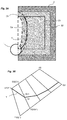
- the program determines a circular zone 30 of radius f f circumscribed in said pocket to be made ( figure 2 ).
- the circular zone of radius r f is then divided into several portions of parametric curves interconnected so as to form a spiral.
- This inlet is for example made by a hole made helically in the material, so as to form a circular orifice 40 of radius r d .
- the determination of the coefficient k is carried out taking into account the engagement area of the tool with respect to the block of material ( Figure 1 B) .
- the value of the coefficient k determines the value of the coefficient C i of radial incrementation and therefore the positioning of the parametric curve portion.
- the coefficient C i of radial incrementation will depend on the position of the tool and the motion vector of the tool.
- the engagement angle ⁇ of the tool 1 in a plane parallel to the vector V of movement of the tool, corresponds to the angle made between an axis A1 joining the center of the tool 1 to the point of intersection between the tool 1 and the block 2 of material and an axis A2 perpendicular to the vector V of movement of the tool, whose coordinates are indicated above.
- the program implements a search of a value to be assigned to the coefficient k to determine the coefficient C i of radial incrementation for which the path of the tool 1 will not result in exceeding the maximum value A max of l memorized engagement area.
- the operation is implemented for a number of points of the curve defined by the variation of the angle a.
- the figure 2 thus shows the spiral path achieved by the tool to achieve a circular area of a closed pocket, taking into account a predefined maximum engagement area.
- the circular area is machined with a helical entry into the block of material.
- the path is divided into six portions C1, C2, C3, C4, C5, C6 of parametric curves, each defined by a coefficient C i of distinct radial increment.
- the computer program of the invention implements the steps described below.
- the program controls the tool 1 so as to make a first pass following a first curve, called the original curve Co.
- the program calculates each subsequent pass that allows to gradually dig the pocket.
- the path T of the tool corresponds to several straight segments connected to each other.
- Curve Cb thus corresponds to the original curve, widened by the distance d of maximum offset.
- the program thus obtains two curves each consisting of several segments whose points are synchronized with each other.
- the trajectories are created using Co ', Cb', taking into account the load of the tool.
- the trajectories are calculated point by point, taking into account the load of the tool to reach each point.
- the load of the tool is defined with respect to the maximum value A max predefined for the engagement area of the tool 1 in the block 2 of material.
- the program proceeds as follows for the determination of the path T of the tool, said path T consisting of a series of points connected to each other.
- the program adds the first point P1 of Co 'in T; it is the starting point of the path to create.
- the definition of the path point T on the segment ⁇ Gi-1, Gi> is a process of search by dichotomy, with at each iteration a calculation of the engagement area.
- the search by dichotomy stops when the size of the search domain falls below the tolerance of the machining.
- the program implements the same process to define the path points on segments ⁇ D3, F3>, ..., ⁇ Dk, Fk>. Likewise, this entire process is performed again for the next two corresponding segments of the original curve Co and the curve Cb.
- the method of the invention can be applied for the machining of all types of material, for example metal, ceramic or resin such as that used in the dental field.
Landscapes
- Physics & Mathematics (AREA)
- Engineering & Computer Science (AREA)
- Geometry (AREA)
- Human Computer Interaction (AREA)
- Manufacturing & Machinery (AREA)
- General Physics & Mathematics (AREA)
- Automation & Control Theory (AREA)
- Numerical Control (AREA)
Applications Claiming Priority (1)
| Application Number | Priority Date | Filing Date | Title |
|---|---|---|---|
| FR1559212A FR3041777B1 (fr) | 2015-09-29 | 2015-09-29 | Procede de determination du trajet d’un outil d’usinage |
Publications (1)
| Publication Number | Publication Date |
|---|---|
| EP3151074A1 true EP3151074A1 (de) | 2017-04-05 |
Family
ID=54545346
Family Applications (1)
| Application Number | Title | Priority Date | Filing Date |
|---|---|---|---|
| EP16190573.2A Withdrawn EP3151074A1 (de) | 2015-09-29 | 2016-09-26 | Verfahren zur bestimmung der bewegungsbahn eines bearbeitungswerkzeugs |
Country Status (2)
| Country | Link |
|---|---|
| EP (1) | EP3151074A1 (de) |
| FR (1) | FR3041777B1 (de) |
Cited By (2)
| Publication number | Priority date | Publication date | Assignee | Title |
|---|---|---|---|---|
| EP3627252A1 (de) | 2018-09-21 | 2020-03-25 | Go2Cam International | Verfahren zur bestimmung des optimalen bewegungspfads eines bearbeitungswerkzeugs, der die bildung von dünnen wänden vermeiden kann |
| CN115167285A (zh) * | 2022-08-03 | 2022-10-11 | 凯氟隆(厦门)密封件有限公司 | 切割路径生成方法、设备及程序产品 |
Citations (4)
| Publication number | Priority date | Publication date | Assignee | Title |
|---|---|---|---|---|
| US20050246052A1 (en) | 2004-04-29 | 2005-11-03 | Surfware, Inc. | Engagement milling |
| US20130151000A1 (en) | 2011-12-12 | 2013-06-13 | Delcam Plc | Method and system for generating cutting paths |
| US20130325165A1 (en) | 2012-06-01 | 2013-12-05 | D.P. Technology Corp. | Profit milling |
| US20140297021A1 (en) | 2011-02-11 | 2014-10-02 | Ecole Polytechnique Federale De Lausanne (Epfl) | High speed pocket milling optimisation |
-
2015
- 2015-09-29 FR FR1559212A patent/FR3041777B1/fr not_active Expired - Fee Related
-
2016
- 2016-09-26 EP EP16190573.2A patent/EP3151074A1/de not_active Withdrawn
Patent Citations (4)
| Publication number | Priority date | Publication date | Assignee | Title |
|---|---|---|---|---|
| US20050246052A1 (en) | 2004-04-29 | 2005-11-03 | Surfware, Inc. | Engagement milling |
| US20140297021A1 (en) | 2011-02-11 | 2014-10-02 | Ecole Polytechnique Federale De Lausanne (Epfl) | High speed pocket milling optimisation |
| US20130151000A1 (en) | 2011-12-12 | 2013-06-13 | Delcam Plc | Method and system for generating cutting paths |
| US20130325165A1 (en) | 2012-06-01 | 2013-12-05 | D.P. Technology Corp. | Profit milling |
Cited By (3)
| Publication number | Priority date | Publication date | Assignee | Title |
|---|---|---|---|---|
| EP3627252A1 (de) | 2018-09-21 | 2020-03-25 | Go2Cam International | Verfahren zur bestimmung des optimalen bewegungspfads eines bearbeitungswerkzeugs, der die bildung von dünnen wänden vermeiden kann |
| FR3086403A1 (fr) | 2018-09-21 | 2020-03-27 | Go2Cam International | Procede de determination du trajet optimal d'un outil d'usinage permettant d'eviter la formation de parois minces |
| CN115167285A (zh) * | 2022-08-03 | 2022-10-11 | 凯氟隆(厦门)密封件有限公司 | 切割路径生成方法、设备及程序产品 |
Also Published As
| Publication number | Publication date |
|---|---|
| FR3041777A1 (fr) | 2017-03-31 |
| FR3041777B1 (fr) | 2019-05-10 |
Similar Documents
| Publication | Publication Date | Title |
|---|---|---|
| EP2900461B1 (de) | Verfahren zur herstellung einer ophthalmischen linse mit einem markierungsschritt zur herstellung permanenter technischer markierungen auf dieser ophthalmischen linse | |
| EP2869982B1 (de) | Verfahren und vorrichtung zur steuerung eines laserstrahls zur herstellung dreidimensionaler objekte mittels schichtlagen | |
| EP2987102B1 (de) | Verfahren zum modellieren eines bauteils, insbesondere einer turbinenschaufel | |
| EP3151074A1 (de) | Verfahren zur bestimmung der bewegungsbahn eines bearbeitungswerkzeugs | |
| FR2809978A1 (fr) | Procede et appareil definissant un trajet d'outil a faible courbure | |
| FR2749950A1 (fr) | Procede pour produire des points discrets definissant le trajet d'un couteau en tenant compte de l'aptitude d'une machine individuelle de maniere a augmenter son efficacite | |
| EP2517078B1 (de) | Bearbeitungsverfahren zur bearbeitung einer seite eines brillenglases | |
| CA2845501A1 (fr) | Procede de surfacage d'une surface d'un verre de lunettes | |
| EP4157722A1 (de) | Verfahren zur schätzung der kollision zwischen mindestens einem stück weltraummüll und einem satelliten | |
| FR3033062A1 (fr) | Procede de determination d'intervalles de tolerance pour le dimensionnement d'une piece | |
| FR2979267A1 (fr) | Procede de fabrication d'une piece par forgeage | |
| EP2359339B1 (de) | Computerunterstütztes entwurfsverfahren zum erzeugen einer oberfläche in einem komplexen system | |
| EP2782709A1 (de) | Verfahren zur herstellung einer kontaktlinse | |
| EP3352031B1 (de) | Verfahren zur bestimmung des bahnes eines fräswerkzeugs zur bearbeitung eines werkstücks vor der feinvorgängen | |
| EP2724201B1 (de) | Adaptives bearbeitungsverfahren für geschmolzene schaufeln | |
| FR2943427A1 (fr) | Procede de decoupe d'une pastille a appliquer sur un substrat courbe | |
| WO2018127637A1 (fr) | Procédé de modification de la trajectoire de coupe de pièces destinées à être découpées dans un matériau souple | |
| EP3627252A1 (de) | Verfahren zur bestimmung des optimalen bewegungspfads eines bearbeitungswerkzeugs, der die bildung von dünnen wänden vermeiden kann | |
| EP3901834A1 (de) | Verfahren zur implementierung eines netzwerks aus künstlichen neuronen in einer integrierten schaltung | |
| FR3058682A1 (fr) | Procede et dispositif d'adaptation du niveau de couple recuperatif d'un vehicule automobile a propulsion electrique | |
| EP2399709B1 (de) | Rechnerisches Simulationsverfahren zur Gestaltung einer peripheren Fassungsrippe auf der Kante eines Brillenglases und Verfahren des Facettierens | |
| EP2213395B1 (de) | Verfahren zur Vorbereitung der Einstellung von Werkzeugen, Vorrichtung zur Vorbereitung der Einstellen von Werkzeugen und Einstellungsverfahren von Werkzeugen | |
| WO2005042181A1 (fr) | Procede de conception d'un outil d'emboutissage pour obtenir une piece dans les tolerances geometriques | |
| EP4432175A1 (de) | Verfahren zur parametrierung einer datenverarbeitungsleitung | |
| FR2931956A1 (fr) | Determination d'une gamme d'usinage d'une piece |
Legal Events
| Date | Code | Title | Description |
|---|---|---|---|
| PUAI | Public reference made under article 153(3) epc to a published international application that has entered the european phase |
Free format text: ORIGINAL CODE: 0009012 |
|
| AK | Designated contracting states |
Kind code of ref document: A1 Designated state(s): AL AT BE BG CH CY CZ DE DK EE ES FI FR GB GR HR HU IE IS IT LI LT LU LV MC MK MT NL NO PL PT RO RS SE SI SK SM TR |
|
| AX | Request for extension of the european patent |
Extension state: BA ME |
|
| 17P | Request for examination filed |
Effective date: 20170926 |
|
| RBV | Designated contracting states (corrected) |
Designated state(s): AL AT BE BG CH CY CZ DE DK EE ES FI FR GB GR HR HU IE IS IT LI LT LU LV MC MK MT NL NO PL PT RO RS SE SI SK SM TR |
|
| STAA | Information on the status of an ep patent application or granted ep patent |
Free format text: STATUS: EXAMINATION IS IN PROGRESS |
|
| 17Q | First examination report despatched |
Effective date: 20200615 |
|
| STAA | Information on the status of an ep patent application or granted ep patent |
Free format text: STATUS: THE APPLICATION IS DEEMED TO BE WITHDRAWN |
|
| 18D | Application deemed to be withdrawn |
Effective date: 20201027 |