EP3151074A1 - Method for determining the path of a machining tool - Google Patents
Method for determining the path of a machining tool Download PDFInfo
- Publication number
- EP3151074A1 EP3151074A1 EP16190573.2A EP16190573A EP3151074A1 EP 3151074 A1 EP3151074 A1 EP 3151074A1 EP 16190573 A EP16190573 A EP 16190573A EP 3151074 A1 EP3151074 A1 EP 3151074A1
- Authority
- EP
- European Patent Office
- Prior art keywords
- tool
- value
- path
- machining
- block
- Prior art date
- Legal status (The legal status is an assumption and is not a legal conclusion. Google has not performed a legal analysis and makes no representation as to the accuracy of the status listed.)
- Withdrawn
Links
Images


Classifications
-
- G—PHYSICS
- G05—CONTROLLING; REGULATING
- G05B—CONTROL OR REGULATING SYSTEMS IN GENERAL; FUNCTIONAL ELEMENTS OF SUCH SYSTEMS; MONITORING OR TESTING ARRANGEMENTS FOR SUCH SYSTEMS OR ELEMENTS
- G05B19/00—Programme-control systems
- G05B19/02—Programme-control systems electric
- G05B19/18—Numerical control [NC], i.e. automatically operating machines, in particular machine tools, e.g. in a manufacturing environment, so as to execute positioning, movement or co-ordinated operations by means of programme data in numerical form
- G05B19/4093—Numerical control [NC], i.e. automatically operating machines, in particular machine tools, e.g. in a manufacturing environment, so as to execute positioning, movement or co-ordinated operations by means of programme data in numerical form characterised by part programming, e.g. entry of geometrical information as taken from a technical drawing, combining this with machining and material information to obtain control information, named part programme, for the NC machine
- G05B19/40937—Numerical control [NC], i.e. automatically operating machines, in particular machine tools, e.g. in a manufacturing environment, so as to execute positioning, movement or co-ordinated operations by means of programme data in numerical form characterised by part programming, e.g. entry of geometrical information as taken from a technical drawing, combining this with machining and material information to obtain control information, named part programme, for the NC machine concerning programming of machining or material parameters, pocket machining
-
- Y—GENERAL TAGGING OF NEW TECHNOLOGICAL DEVELOPMENTS; GENERAL TAGGING OF CROSS-SECTIONAL TECHNOLOGIES SPANNING OVER SEVERAL SECTIONS OF THE IPC; TECHNICAL SUBJECTS COVERED BY FORMER USPC CROSS-REFERENCE ART COLLECTIONS [XRACs] AND DIGESTS
- Y02—TECHNOLOGIES OR APPLICATIONS FOR MITIGATION OR ADAPTATION AGAINST CLIMATE CHANGE
- Y02P—CLIMATE CHANGE MITIGATION TECHNOLOGIES IN THE PRODUCTION OR PROCESSING OF GOODS
- Y02P90/00—Enabling technologies with a potential contribution to greenhouse gas [GHG] emissions mitigation
- Y02P90/02—Total factory control, e.g. smart factories, flexible manufacturing systems [FMS] or integrated manufacturing systems [IMS]
Definitions
- the present invention relates to a method for determining the path of a machining tool.
- the machine includes a tool, which can take various forms, controlled at high speed by CAM (Computer Aided Manufacturing) software to remove material from a block of raw material. The removal of material is carried out by several successive passes and possibly at different depths.
- CAM Computer Aided Manufacturing
- the open pocket is directly accessible by the tool from outside the block of material.
- the closed bag is circumscribed by material and requires beforehand, before starting machining, to drive the tool into the block of material. Recently, it has been proposed to machine closed pockets by driving the tool in a spiral path.
- the object of the invention is to propose a method for determining the path of a machining tool, allowing optimization of the path performed which reduces the machining time while respecting a constant and controlled tool load. to preserve the tool and thus increase its life.
- the path of the tool follows a spiral cut into several portions, and in that, for each new portion of the spiral, the step of determination of the motion vector of the tool is implemented taking into account a coefficient, called radial incrementation.
- the radial incrementation coefficient is determined from a radius of the preceding spiral portion, a tool dimension parameter, a maximum offset of the stored machining and a coefficient.
- the latter coefficient takes a determined value after a search by dichotomy, said value of the coefficient being chosen in a range in which the engagement area value of the tool is less than said maximum stored value.
- each portion of the path is made at an angle of 360 °.
- the path of the tool consists of several rectilinear portions, each portion being plotted between an initial point and an end point following said determined motion vector for a tool engagement area value less than said maximum value.
- each end point of a first portion becomes the initial point of a second portion of the path and that the end point of said second portion is determined by a dichotomy, said point being chosen so that the value of the the engagement area of the tool in the raw material block is less than said maximum value.
- the method described above will be implemented using a computer program to be run on a computer.
- This computer program will preferably be stored on a storage medium readable by a computer.
- the invention relates to a method implemented by a numerically controlled machine.
- the method of the invention makes it possible to determine the path of a machining tool 1 of the numerically controlled machine. It is realized through a computer program executed by a processing unit of the machine or associated with it. It is stored in said processing unit on a readable memory medium. All types of media, integrated in the machine or in a separate processing unit, removable or accessible through a communication network, and conventionally used to store a computer program, may be considered.
- the program comprises a plurality of software modules for controlling the path of the tool for manufacturing a workpiece by machining.
- a first software module is for example executed by the processing unit for machining a closed pocket in a block of raw material.
- a second software module is for example executed by the processing unit for machining an open pocket in the block of raw material.
- Block 2 of raw material from which the piece is obtained may have any initial shape.
- the method for determining the path T of the tool 1 is constructed so as to take into account the load of the tool.
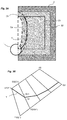
- the load of the tool is a function of the engagement area of the tool, that is to say of the contact surface between the tool and the material during machining ( Figure 1 B) .
- a maximum value A max of engagement area is predetermined, for example by the operator, and stored by the processing unit in a memory accessible by the computer program.
- the program determines a circular zone 30 of radius f f circumscribed in said pocket to be made ( figure 2 ).
- the circular zone of radius r f is then divided into several portions of parametric curves interconnected so as to form a spiral.
- This inlet is for example made by a hole made helically in the material, so as to form a circular orifice 40 of radius r d .
- the determination of the coefficient k is carried out taking into account the engagement area of the tool with respect to the block of material ( Figure 1 B) .
- the value of the coefficient k determines the value of the coefficient C i of radial incrementation and therefore the positioning of the parametric curve portion.
- the coefficient C i of radial incrementation will depend on the position of the tool and the motion vector of the tool.
- the engagement angle ⁇ of the tool 1 in a plane parallel to the vector V of movement of the tool, corresponds to the angle made between an axis A1 joining the center of the tool 1 to the point of intersection between the tool 1 and the block 2 of material and an axis A2 perpendicular to the vector V of movement of the tool, whose coordinates are indicated above.
- the program implements a search of a value to be assigned to the coefficient k to determine the coefficient C i of radial incrementation for which the path of the tool 1 will not result in exceeding the maximum value A max of l memorized engagement area.
- the operation is implemented for a number of points of the curve defined by the variation of the angle a.
- the figure 2 thus shows the spiral path achieved by the tool to achieve a circular area of a closed pocket, taking into account a predefined maximum engagement area.
- the circular area is machined with a helical entry into the block of material.
- the path is divided into six portions C1, C2, C3, C4, C5, C6 of parametric curves, each defined by a coefficient C i of distinct radial increment.
- the computer program of the invention implements the steps described below.
- the program controls the tool 1 so as to make a first pass following a first curve, called the original curve Co.
- the program calculates each subsequent pass that allows to gradually dig the pocket.
- the path T of the tool corresponds to several straight segments connected to each other.
- Curve Cb thus corresponds to the original curve, widened by the distance d of maximum offset.
- the program thus obtains two curves each consisting of several segments whose points are synchronized with each other.
- the trajectories are created using Co ', Cb', taking into account the load of the tool.
- the trajectories are calculated point by point, taking into account the load of the tool to reach each point.
- the load of the tool is defined with respect to the maximum value A max predefined for the engagement area of the tool 1 in the block 2 of material.
- the program proceeds as follows for the determination of the path T of the tool, said path T consisting of a series of points connected to each other.
- the program adds the first point P1 of Co 'in T; it is the starting point of the path to create.
- the definition of the path point T on the segment ⁇ Gi-1, Gi> is a process of search by dichotomy, with at each iteration a calculation of the engagement area.
- the search by dichotomy stops when the size of the search domain falls below the tolerance of the machining.
- the program implements the same process to define the path points on segments ⁇ D3, F3>, ..., ⁇ Dk, Fk>. Likewise, this entire process is performed again for the next two corresponding segments of the original curve Co and the curve Cb.
- the method of the invention can be applied for the machining of all types of material, for example metal, ceramic or resin such as that used in the dental field.
Abstract
L'invention concerne un procédé de détermination du trajet d'un outil (1) d'usinage pour fabriquer une pièce (21, 22) par usinage dans un bloc (2) de matière brute, comportant les étapes suivantes : - Détermination de la position de l'outil (1), - Détermination du vecteur (V) de mouvement de l'outil en tenant compte de ladite position, - Détermination d'une valeur d'aire d'engagement ( A ) de l'outil par rapport au bloc (2) de matière brute à partir du vecteur (V) de mouvement de l'outil déterminé, - Comparaison de ladite valeur d'aire d'engagement calculée avec une valeur maximale ( A max ) mémorisée, - Modification du vecteur (V) de mouvement de l'outil tant que la valeur d'aire d'engagement est supérieure à ladite valeur maximale mémorisée.The invention relates to a method for determining the path of a tool (1) for machining a workpiece (21, 22) by machining in a block (2) of raw material, comprising the following steps: - Determination of the position of the tool (1), - Determination of the vector (V) of movement of the tool taking into account said position, Determining a value of engagement area (A) of the tool relative to the block (2) of raw material from the vector (V) of movement of the determined tool, Comparing said calculated engagement area value with a stored maximum value (A max), - Changing the vector (V) of movement of the tool as the value of engagement area is greater than said maximum value stored.
Description
La présente invention se rapporte à un procédé de détermination du trajet d'un outil d'usinage.The present invention relates to a method for determining the path of a machining tool.
Aujourd'hui, la fabrication d'une pièce par usinage est réalisée en employant une machine à commande numérique. La machine comporte un outil, pouvant prendre différentes formes, commandé à haute vitesse par un logiciel de FAO (Fabrication Assistée par Ordinateur) pour enlever de la matière dans un bloc de matière brut. L'enlèvement de matière est réalisé par plusieurs passes successives et éventuellement à différentes profondeurs. Dans la fabrication d'une pièce par usinage, on distingue l'usinage des poches ouvertes de l'usinage des poches fermées. La poche ouverte est directement accessible par l'outil par l'extérieur du bloc de matière. La poche fermée est circonscrite par de la matière et nécessite au préalable, avant de commencer l'usinage, d'enfoncer l'outil dans le bloc de matière. Récemment, il a été proposé d'usiner les poches fermées en pilotant l'outil selon une trajectoire en spirale. Ce type de trajectoire permet en effet de tenir compte de la charge de l'outil contre la matière, améliorant ainsi sa durée de vie. La demande de brevet
La solution décrite dans le document
D'autres solutions d'usinage sont également décrites dans les documents
Le but de l'invention est de proposer un procédé de détermination du trajet d'un outil d'usinage, permettant une optimisation du trajet effectué ce qui réduit la durée d'usinage, tout en respectant une charge de l'outil constante et contrôlée pour préserver l'outil et ainsi augmenter sa durée de vie.The object of the invention is to propose a method for determining the path of a machining tool, allowing optimization of the path performed which reduces the machining time while respecting a constant and controlled tool load. to preserve the tool and thus increase its life.
Ce but est atteint par un procédé de détermination du trajet d'un outil d'usinage pour fabriquer une pièce par usinage dans un bloc de matière brute, ledit procédé comportant les étapes suivantes :
- Détermination de la position de l'outil,
- Détermination du vecteur de mouvement de l'outil en tenant compte de ladite position,
- Détermination d'une valeur d'aire d'engagement de l'outil par rapport au bloc de matière brute à partir du vecteur de mouvement de l'outil déterminé,
- Comparaison de ladite valeur d'aire d'engagement calculée avec une valeur maximale mémorisée,
- Modification du vecteur de mouvement de l'outil tant que la valeur d'aire d'engagement est supérieure à ladite valeur maximale mémorisée.
- Determination of the position of the tool,
- Determination of the motion vector of the tool taking into account said position,
- Determining a value of engagement area of the tool relative to the block of raw material from the motion vector of the determined tool,
- Comparing said calculated engagement area value with a stored maximum value,
- Changing the motion vector of the tool as long as the engagement area value is greater than said stored maximum value.
Avantageusement, lors de l'usinage d'une poche fermée dans ledit bloc de matière brute, le trajet de l'outil suit une spirale découpée en plusieurs portions, et en ce que, pour chaque nouvelle portion de la spirale, l'étape de détermination du vecteur de mouvement de l'outil est mise en oeuvre en tenant compte d'un coefficient, dit d'incrémentation radiale.Advantageously, during the machining of a closed pocket in said block of raw material, the path of the tool follows a spiral cut into several portions, and in that, for each new portion of the spiral, the step of determination of the motion vector of the tool is implemented taking into account a coefficient, called radial incrementation.
Avantageusement, le coefficient d'incrémentation radiale est déterminé à partir d'un rayon de la portion de spirale précédente, d'un paramètre de dimension de l'outil, d'un décalage maximal de l'usinage mémorisé et d'un coefficient. Selon une particularité de l'invention, ce dernier coefficient prend une valeur déterminée à l'issue d'une recherche par dichotomie, ladite valeur du coefficient étant choisie dans un intervalle dans lequel la valeur d'aire d'engagement de l'outil est inférieure à ladite valeur maximale mémorisée.Advantageously, the radial incrementation coefficient is determined from a radius of the preceding spiral portion, a tool dimension parameter, a maximum offset of the stored machining and a coefficient. According to a feature of the invention, the latter coefficient takes a determined value after a search by dichotomy, said value of the coefficient being chosen in a range in which the engagement area value of the tool is less than said maximum stored value.
Selon l'invention, chaque portion du trajet est réalisée sur un angle de 360°. Avantageusement, lors de l'usinage d'une poche ouverte dans ledit bloc de matière, le trajet de l'outil est constitué de plusieurs portions rectilignes, chaque portion étant tracée entre un point initial et un point final suivant ledit vecteur de mouvement déterminé pour une valeur d'aire d'engagement de l'outil inférieure à ladite valeur maximale. Dans cette situation, chaque point final d'une première portion devient le point initial d'une deuxième portion du trajet et en ce que le point final de ladite deuxième portion est déterminé par dichotomie, ledit point étant choisi pour que la valeur de l'aire d'engagement de l'outil dans le bloc de matière brute soit inférieure à ladite valeur maximale.According to the invention, each portion of the path is made at an angle of 360 °. Advantageously, when machining an open pocket in said block of material, the path of the tool consists of several rectilinear portions, each portion being plotted between an initial point and an end point following said determined motion vector for a tool engagement area value less than said maximum value. In this situation, each end point of a first portion becomes the initial point of a second portion of the path and that the end point of said second portion is determined by a dichotomy, said point being chosen so that the value of the the engagement area of the tool in the raw material block is less than said maximum value.
Le procédé décrit ci-dessus sera mis en oeuvre à l'aide d'un programme d'ordinateur destiné à être exécuté sur un ordinateur. Ce programme d'ordinateur sera préférentiellement stocké sur un support de stockage lisible par un ordinateur.The method described above will be implemented using a computer program to be run on a computer. This computer program will preferably be stored on a storage medium readable by a computer.
D'autres caractéristiques et avantages vont apparaître dans la description détaillée qui suit faite en regard des dessins annexés dans lesquels :
- Les
figures 1 A et 1B illustrent le principe d'usinage d'une pièce dans un bloc de matière, - La
figure 2 représente le trajet suivi par un outil pour l'usinage d'une poche fermée, en mettant en oeuvre le procédé de l'invention, - Les
figures 3A et 3B représentent le trajet suivi par un outil pour l'usinage d'une poche ouverte, en mettant en oeuvre le procédé de l'invention.
- The
Figures 1A and 1B illustrate the principle of machining a part in a block of material, - The
figure 2 represents the path followed by a tool for machining a closed pocket, by implementing the method of the invention, - The
Figures 3A and 3B represent the path followed by a tool for machining an open pocket, by implementing the method of the invention.
L'invention concerne un procédé mis en oeuvre par une machine à commande numérique. Le procédé de l'invention permet de déterminer le trajet d'un outil 1 d'usinage de la machine à commande numérique. Il est réalisé grâce à un programme informatique exécuté par une unité de traitement de la machine ou associée à celle-ci. Il est mémorisé dans ladite unité de traitement sur un support mémoire lisible. Tous les types de supports, intégrés à la machine ou dans une unité de traitement distincte, amovibles ou accessibles à travers un réseau de communication, et classiquement utilisés pour mémoriser un programme informatique, pourront être envisagés.The invention relates to a method implemented by a numerically controlled machine. The method of the invention makes it possible to determine the path of a
Ledit programme comporte plusieurs modules logiciels destinés à commander le trajet de l'outil pour la fabrication d'une pièce par usinage. Un premier module logiciel est par exemple exécuté par l'unité de traitement pour usiner une poche fermée dans un bloc de matière brut. Un deuxième module logiciel est par exemple exécuté par l'unité de traitement pour usiner une poche ouverte dans le bloc de matière brut.The program comprises a plurality of software modules for controlling the path of the tool for manufacturing a workpiece by machining. A first software module is for example executed by the processing unit for machining a closed pocket in a block of raw material. A second software module is for example executed by the processing unit for machining an open pocket in the block of raw material.
Le bloc 2 de matière brut à partir duquel la pièce est obtenue peut présenter une forme initiale quelconque.
Selon l'invention, le procédé de détermination du trajet T de l'outil 1 est construit de manière à prendre en compte la charge de l'outil. Dans l'invention, la charge de l'outil est fonction de l'aire d'engagement de l'outil, c'est-à-dire de la surface de contact entre l'outil et la matière lors de l'usinage (
En outre, on verra ci-dessous que le trajet de l'outil est déterminé point par point. Le point N+1 est en effet déterminé à partir de la passe précédente.In addition, it will be seen below that the path of the tool is determined point by point. The point N + 1 is indeed determined from the previous pass.
Pour l'usinage d'une poche fermée 20 dans un bloc 2 de matière brute, le programme détermine une zone circulaire 30 de rayon rf circonscrite dans ladite poche à réaliser (
De manière connue, l'usinage d'une poche fermée débute toujours par une entrée dans la matière. Cette entrée est par exemple réalisée par un trou réalisé en hélice dans la matière, de manière à former un orifice 40 circulaire de rayon rd. In known manner, the machining of a closed pocket always starts with an entry into the material. This inlet is for example made by a hole made helically in the material, so as to form a
Sur chaque courbe paramétrique, la position de l'outil est déterminée par les coordonnées x, y suivantes : ![]()
![]()
![]()
![]()
Dans lesquelles :
- x 0, y 0 correspondent aux coordonnées du centre de la zone circulaire à réaliser.
- Ri définit le rayon de la portion de courbe paramétrique i par la relation suivante :
- ∘

- ∘
- a correspond à la position angulaire de l'outil par rapport à un axe de référence passant par le centre du cercle à usiner, ledit axe étant par exemple horizontal.
- Ci correspond à un coefficient, dit d'incrémentation radiale, définissant chaque portion i (i allant de 1 à n) de courbe paramétrique par rapport au centre de la zone circulaire à usiner. Ci est par exemple redéfini à chaque variation de 360° de l'angle a.
- x 0 , y 0 correspond to the coordinates of the center of the circular zone to be produced.
- R i defines the radius of the parametric curve portion i by the following relation:
- ∘
- ∘
- a corresponds to the angular position of the tool relative to a reference axis passing through the center of the circle to be machined, said axis being for example horizontal.
- C i corresponds to a coefficient, called radial incrementation, defining each portion i (i ranging from 1 to n) of parametric curve with respect to the center of the circular zone to be machined. C i is for example redefined at each 360 ° variation of the angle a.
Le coefficient Ci d'incrémentation radiale est défini par la relation suivante : ![]()
![]()
Dans laquelle :
- d correspond au décalage maximal prédéfini pour l'usinage.
- R correspond au rayon de l'outil.
- k correspond à un coefficient dont la détermination sera expliquée ci-après.
- d is the predefined maximum offset for machining.
- R is the radius of the tool.
- k corresponds to a coefficient whose determination will be explained below.
Pour la première portion de courbe, on désigne : ![]()
![]()
- Avec rd qui correspond au rayon de l'hélice créé pour percer initialement la poche.
- With r d which corresponds to the radius of the helix created to initially pierce the pocket.
Selon l'invention, la détermination du coefficient k est réalisée en tenant compte de l'aire d'engagement de l'outil par rapport au bloc de matière (![]()
![]()
Dans laquelle :
- α correspond à l'angle d'engagement de l'outil dans le bloc de matière (
figures 1 A et 1 B ). - r correspond au rayon de coupe effectif de l'outil à sa position actuelle, ledit rayon de coupe effectif correspondant à la distance maximale entre l'axe de l'outil et les points de contact entre l'outil et le bloc de matière. Si l'outil est de forme cylindrique, ce rayon de coupe correspond au rayon R de l'outil.
- h correspond à la hauteur d'outil en contact avec le bloc de matière.
- α corresponds to the angle of engagement of the tool in the block of material (
Figures 1A and 1B ). - r corresponds to the actual cutting radius of the tool at its current position, said effective cutting radius corresponding to the maximum distance between the tool axis and the points of contact between the tool and the block of material. If the tool is cylindrical in shape, this cutting radius corresponds to the radius R of the tool.
- h corresponds to the height of the tool in contact with the block of material.
La valeur du coefficient k détermine la valeur du coefficient Ci d'incrémentation radiale et donc le positionnement de la portion de courbe paramétrique.The value of the coefficient k determines the value of the coefficient C i of radial incrementation and therefore the positioning of the parametric curve portion.
En outre, du coefficient Ci d'incrémentation radiale vont dépendre la position de l'outil et le vecteur de mouvement de l'outil. En effet, pour chaque coefficient Ci , les coordonnées x, y de position de l'outil et les coordonnées Vx, Vy du vecteur V de mouvement de l'outil sont définies par les relations suivantes : ![]()
![]()
![]()
![]()
![]()
![]()
![]()
![]()
La position de l'outil 1 et le vecteur V de mouvement de l'outil 1 permettent ensuite au programme de déterminer l'angle d'engagement α de l'outil dans le bloc de matière et d'en déduire ainsi l'aire d'engagement A définie ci-dessus. Pour rappel, comme représenté sur la
Ainsi le programme met en place une recherche d'une valeur à affecter au coefficient k pour déterminer le coefficient Ci d'incrémentation radiale pour lequel le trajet de l'outil 1 n'entraînera pas un dépassement de la valeur maximale Amax de l'aire d'engagement mémorisée. L'opération est mise en oeuvre pour un certain nombre de points de la courbe définis par la variation de l'angle a.Thus, the program implements a search of a value to be assigned to the coefficient k to determine the coefficient C i of radial incrementation for which the path of the
Une fois la valeur du coefficient k déterminée, et donc la définition d'un coefficient Ci d'incrémentation radiale terminée par le programme, une suite de points, formant la portion de courbe, est calculée à partir des paramètres évoqués ci-dessus, en faisant varier l'angle a de 0 à 360°.Once the value of the coefficient k has been determined, and thus the definition of a coefficient C i of radial incrementation completed by the program, a sequence of points, forming the portion of the curve, is calculated from the parameters mentioned above, by varying the angle α from 0 to 360 °.
L'opération est réitérée par le programme tant que la condition Ri = rf n'est pas remplie.The operation is reiterated by the program as long as the condition R i = r f is not fulfilled.
La
Pour réaliser une poche ouverte 22, le principe de l'invention qui consiste à tenir compte d'une valeur maximale Amax mémorisée pour l'aire d'engagement de l'outil s'applique également.To achieve an
Pour réaliser une poche ouverte 22 par usinage du bloc 2 de matière, le programme informatique de l'invention met en oeuvre les étapes décrites ci-dessous.To make an
Le principe de fonctionnement est explicité en relation avec les
Sur la
Dans une première étape, le programme commande l'outil 1 de manière à réaliser une première passe suivant une première courbe, dite courbe d'origine Co.In a first step, the program controls the
Une fois la première passe réalisée, le programme calcule chaque passe suivante qui permet de creuser progressivement la poche.Once the first pass is made, the program calculates each subsequent pass that allows to gradually dig the pocket.
Selon l'invention, en référence à la
Pour déterminer le trajet T de l'outil 1 sur une nouvelle passe, le programme procède de la manière suivante :
- Initialement, le programme crée une première courbe cible, notée Cb sur la figure, telle que:
- o la courbe Cb se trouve à droite de la courbe d'origine Co,
- o la courbe Cb soit un décalage de la courbe d'origine Co, la distance d de décalage étant le décalage maximal prédéfini pour l'usinage,
- o l'ordre d'apparition de chaque segment de la courbe Cb respecte l'ordre d'apparition d'un segment correspondant de la courbe d'origine Co.
- Initially, the program creates a first target curve, denoted Cb in the figure, such that:
- o the curve Cb is to the right of the original curve Co,
- the curve Cb is an offset of the original curve Co, the offset distance d being the maximum predefined offset for the machining,
- o the order of appearance of each segment of the curve Cb respects the order of appearance of a corresponding segment of the original curve Co.
La courbe Cb correspond ainsi à la courbe d'origine, élargie de la distance d de décalage maximal.Curve Cb thus corresponds to the original curve, widened by the distance d of maximum offset.
Le programme obtient ainsi deux courbes constituées chacune de plusieurs segments dont les points sont synchronisés entre eux.The program thus obtains two curves each consisting of several segments whose points are synchronized with each other.
Pour mieux expliquer le principe de fonctionnement, on définit les paramètres suivants :
- R : rayon de l'outil,
- d : décalage entre les passes, correspondant au décalage maximal,
- Co' : courbe de plusieurs segments consécutifs qui suivent la courbe d'origine Co,
- Cb' : courbe de plusieurs segments consécutifs qui suivent la courbe Cb ;
- n : le nombre de points sur Co' et Cb',
- P1, P2, ..., Pn, les points sur Co',
- Q1, Q2, ..., Qn, les points sur Cb',
- T : trajet à créer, sous forme d'une suite de points.
- R: radius of the tool,
- d: shift between passes, corresponding to the maximum offset,
- Co ': curve of several consecutive segments which follow the curve of origin Co,
- Cb ': curve of several consecutive segments which follow the curve Cb;
- n: the number of points on Co 'and Cb',
- P1, P2, ..., Pn, the points on Co ',
- Q1, Q2, ..., Qn, the points on Cb ',
- T: path to create, in the form of a sequence of points.
Ensuite les trajectoires sont créées à l'aide des Co', Cb', prenant en compte la charge de l'outil. Les trajectoires sont calculées point par point, en tenant compte de la charge de l'outil pour atteindre chacun des points.Then the trajectories are created using Co ', Cb', taking into account the load of the tool. The trajectories are calculated point by point, taking into account the load of the tool to reach each point.
Comme pour la réalisation d'une poche fermée, la charge de l'outil est définie par rapport à la valeur maximale A max prédéfinie pour l'aire d'engagement de l'outil 1 dans le bloc 2 de matière. L'aire d'engagement de l'outil est définie par la relation : ![]()
![]()
Dans laquelle :
- α correspond à l'angle d'engagement de l'outil dans le bloc de matière.
- r correspond au rayon de coupe effectif de l'outil à sa position actuelle.
- h correspond à la hauteur d'outil en contact avec le bloc de matière.
- α corresponds to the angle of engagement of the tool in the block of material.
- r is the actual cutting radius of the tool at its current position.
- h corresponds to the height of the tool in contact with the block of material.
En relation avec la
Le programme ajoute le premier point P1 de Co' dans T; c'est le point de départ du trajet à créer.The program adds the first point P1 of Co 'in T; it is the starting point of the path to create.
Ensuite le programme détermine le point suivant du trajet, en mettant en oeuvre les étapes suivantes :
- division des deux segments <P1,P2> et <Q1,Q2> en k segments chacun, de longueur égale; k étant choisi pour que la longueur de chaque segment obtenu soit inférieure ou égale à

- Enregistrement des deux suites de points ainsi obtenus, c'est-à-dire :
- ▪ D1, D2, ...,Dk; points obtenus en divisant le segment <P1,P2>, avec D1=P1, Dk=P2 ;
- ▪ F1, F2, ... Fk; points obtenus en divisant le segment <Q1,Q2>, avec F1=Q1, Fk=Q2 ;
- définition d'un point de trajet sur le segment <D2, F2>, correspondant au deuxième point du trajet T en :
- ▪ soustrayant la partie qui est hors de la poche du segment <D2,F2>; le nouveau segment est alors noté <D2,F2'>,
- ▪ divisant le segment <D2,F2'> ainsi obtenu en m segments de longueur égale, m étant choisi pour que la longueur de chaque segment obtenu soit inférieure ou égale à 0.2*D ; les nouveaux points obtenus sont notés G1, G2, ..., Gm; avec G1=D2, Gm=F2',
- ▪ calculant l'aire d'engagement sur les points G2, G3, ..., Gm, en tenant compte du vecteur de mouvement de l'outil suivant chaque segment <P1,G2>, <P1,G3> , .. <P1,Gm> respectivement ;
- si sur un point Gi (i=2,3, ... m), l'aire d'engagement déterminée est supérieure ou égale à la valeur maximale A max, alors le point du trajet T est défini sur le segment <Gi-1 ,Gi>.
- division of the two segments <P1, P2> and <Q1, Q2> into k segments each, of equal length; k being chosen so that the length of each segment obtained is less than or equal to
- Registration of the two series of points thus obtained, that is to say:
- ▪ D1, D2, ..., Dk; points obtained by dividing the segment <P1, P2>, with D1 = P1, Dk = P2;
- ▪ F1, F2, ... Fk; points obtained by dividing the segment <Q1, Q2>, with F1 = Q1, Fk = Q2;
- defining a path point on the segment <D2, F2> corresponding to the second point of the path T in:
- ▪ subtracting the part that is out of the segment pocket <D2, F2>; the new segment is then noted <D2, F2 '>,
- ▪ dividing the segment <D2, F2 '> thus obtained into m segments of equal length, m being chosen so that the length of each segment obtained is less than or equal to 0.2 * D; the new points obtained are denoted G1, G2, ..., Gm; with G1 = D2, Gm = F2 ',
- ▪ calculating the engagement area on points G2, G3, ..., Gm, taking into account the motion vector of the tool following each segment <P1, G2>, <P1, G3>, .. < P1, Gm>respectively;
- if on a point Gi (i = 2.3, ... m), the determined engagement area is greater than or equal to the maximum value A max , then the point of the path T is defined on the segment <
Gi 1, Gi>.
La définition du point de trajet T sur le segment <Gi-1 ,Gi> est un processus de recherche par dichotomie, avec à chaque itération un calcul de l'aire d'engagement. La recherche par dichotomie s'arrête lorsque la taille du domaine de recherche devient inférieure à la tolérance de l'usinage.The definition of the path point T on the segment <Gi-1, Gi> is a process of search by dichotomy, with at each iteration a calculation of the engagement area. The search by dichotomy stops when the size of the search domain falls below the tolerance of the machining.
Le programme met en oeuvre le même processus pour définir les points de trajet sur les segments <D3,F3>, ..., <Dk,Fk>. De même, tout ce processus est de nouveau réalisé pour les deux segments correspondants suivants de la courbe d'origine Co et de la courbe Cb.The program implements the same process to define the path points on segments <D3, F3>, ..., <Dk, Fk>. Likewise, this entire process is performed again for the next two corresponding segments of the original curve Co and the curve Cb.
Que ce soit pour réaliser une poche fermée ou une poche ouverte, le procédé de l'invention mis en oeuvre par l'exécution du programme présente de nombreux avantages, parmi lesquels :
- une diminution de la longueur du trajet,
- une diminution de la durée d'usinage,
- une augmentation de la durée de vie de l'outil en tenant compte de l'aire d'engagement de l'outil dans le bloc de matière et non seulement de son angle d'engagement.
- a decrease in the length of the trip,
- a reduction in the machining time,
- an increase in the life of the tool taking into account the engagement area of the tool in the block of material and not only its angle of engagement.
Le procédé de l'invention pourra s'appliquer pour l'usinage de tous types de matière, par exemple métallique, céramique ou résine comme celle employée dans le domaine dentaire.The method of the invention can be applied for the machining of all types of material, for example metal, ceramic or resin such as that used in the dental field.
Claims (9)
Applications Claiming Priority (1)
| Application Number | Priority Date | Filing Date | Title |
|---|---|---|---|
| FR1559212A FR3041777B1 (en) | 2015-09-29 | 2015-09-29 | METHOD OF DETERMINING THE PATH OF A MACHINING TOOL |
Publications (1)
| Publication Number | Publication Date |
|---|---|
| EP3151074A1 true EP3151074A1 (en) | 2017-04-05 |
Family
ID=54545346
Family Applications (1)
| Application Number | Title | Priority Date | Filing Date |
|---|---|---|---|
| EP16190573.2A Withdrawn EP3151074A1 (en) | 2015-09-29 | 2016-09-26 | Method for determining the path of a machining tool |
Country Status (2)
| Country | Link |
|---|---|
| EP (1) | EP3151074A1 (en) |
| FR (1) | FR3041777B1 (en) |
Cited By (1)
| Publication number | Priority date | Publication date | Assignee | Title |
|---|---|---|---|---|
| EP3627252A1 (en) | 2018-09-21 | 2020-03-25 | Go2Cam International | Method for determining the optimal path of a machining tool to prevent the formation of thin walls |
Citations (4)
| Publication number | Priority date | Publication date | Assignee | Title |
|---|---|---|---|---|
| US20050246052A1 (en) | 2004-04-29 | 2005-11-03 | Surfware, Inc. | Engagement milling |
| US20130151000A1 (en) | 2011-12-12 | 2013-06-13 | Delcam Plc | Method and system for generating cutting paths |
| US20130325165A1 (en) | 2012-06-01 | 2013-12-05 | D.P. Technology Corp. | Profit milling |
| US20140297021A1 (en) | 2011-02-11 | 2014-10-02 | Ecole Polytechnique Federale De Lausanne (Epfl) | High speed pocket milling optimisation |
-
2015
- 2015-09-29 FR FR1559212A patent/FR3041777B1/en not_active Expired - Fee Related
-
2016
- 2016-09-26 EP EP16190573.2A patent/EP3151074A1/en not_active Withdrawn
Patent Citations (4)
| Publication number | Priority date | Publication date | Assignee | Title |
|---|---|---|---|---|
| US20050246052A1 (en) | 2004-04-29 | 2005-11-03 | Surfware, Inc. | Engagement milling |
| US20140297021A1 (en) | 2011-02-11 | 2014-10-02 | Ecole Polytechnique Federale De Lausanne (Epfl) | High speed pocket milling optimisation |
| US20130151000A1 (en) | 2011-12-12 | 2013-06-13 | Delcam Plc | Method and system for generating cutting paths |
| US20130325165A1 (en) | 2012-06-01 | 2013-12-05 | D.P. Technology Corp. | Profit milling |
Cited By (2)
| Publication number | Priority date | Publication date | Assignee | Title |
|---|---|---|---|---|
| EP3627252A1 (en) | 2018-09-21 | 2020-03-25 | Go2Cam International | Method for determining the optimal path of a machining tool to prevent the formation of thin walls |
| FR3086403A1 (en) | 2018-09-21 | 2020-03-27 | Go2Cam International | METHOD FOR DETERMINING THE OPTIMAL ROUTE OF A MACHINING TOOL TO AVOID THE FORMATION OF THIN WALLS |
Also Published As
| Publication number | Publication date |
|---|---|
| FR3041777B1 (en) | 2019-05-10 |
| FR3041777A1 (en) | 2017-03-31 |
Similar Documents
| Publication | Publication Date | Title |
|---|---|---|
| EP2869982B1 (en) | Method and apparatus for controlling a laser beam for manufacturing three-dimensional objects by means of stacked layers | |
| FR2996160A1 (en) | METHOD FOR MANUFACTURING AN OPHTHALMIC LENS COMPRISING A MARKING STEP FOR PERMANENT BRANDS ON THE OPHTHALMIC LENS | |
| FR2809978A1 (en) | Method of internal machining of aerospace components involves forming spirals between curved cutting path contours of workpiece | |
| WO2013030495A1 (en) | Method of surfacing a surface of a spectacle lens | |
| FR2749950A1 (en) | METHOD FOR PRODUCING DISCRETE POINTS DEFINING THE TRACK OF A KNIFE BY TAKING ACCOUNT OF THE ABILITY OF AN INDIVIDUAL MACHINE TO INCREASE ITS EFFECTIVENESS | |
| EP2517078B1 (en) | Machining method for machining one face of a spectacle lens | |
| EP3151074A1 (en) | Method for determining the path of a machining tool | |
| FR3033062A1 (en) | METHOD FOR DETERMINING TOLERANCE INTERVALS FOR SIZING A WORKPIECE | |
| CH688906A5 (en) | A method for generating a set of machining conditions. | |
| WO2021240487A1 (en) | Method for adjusting the orbital path of a satellite | |
| EP2782709B1 (en) | Method for obtaining an ophthalmic lens | |
| FR2991893A1 (en) | TUBE CRUNCHING METHOD AND ASSOCIATED CRYSTATING MACHINE | |
| EP2359339B1 (en) | Computer-assisted design method for generating a surface in a complex system | |
| CA2843686A1 (en) | Method for manufacturing a component using forging | |
| EP3352031A1 (en) | Method for determining the path of a milling tool for machining a workpiece before the finished step | |
| EP2409181B1 (en) | Method for cutting a patch to be applied onto a curved substrate | |
| EP2724201B1 (en) | Adaptive machining method for smelted blades | |
| CH689182A5 (en) | Device and EDM milling process in three dimensions with a rotary tool electrode. | |
| EP3627252A1 (en) | Method for determining the optimal path of a machining tool to prevent the formation of thin walls | |
| EP1262308B1 (en) | Process for making an optical component, mould for this process and optical component obtained by this process | |
| EP3901834A1 (en) | Method for implementing an artificial neural network in an integrated circuit | |
| FR3058682A1 (en) | METHOD AND DEVICE FOR ADAPTING THE RECOVERABLE TORQUE LEVEL OF A MOTOR VEHICLE WITH ELECTRIC PROPULSION | |
| EP2399709B1 (en) | Process for the calculation and simulation of a peripheral mounting rib on the edge of a spectacle lens and bevelling process | |
| EP2213395B1 (en) | Method for preparing adjustments of tools, device for preparing adjustments of tools, and method for adjusting tools | |
| WO2005042181A1 (en) | Method for designing a swaging tool to obtain a component within geometric tolerances |
Legal Events
| Date | Code | Title | Description |
|---|---|---|---|
| PUAI | Public reference made under article 153(3) epc to a published international application that has entered the european phase |
Free format text: ORIGINAL CODE: 0009012 |
|
| AK | Designated contracting states |
Kind code of ref document: A1 Designated state(s): AL AT BE BG CH CY CZ DE DK EE ES FI FR GB GR HR HU IE IS IT LI LT LU LV MC MK MT NL NO PL PT RO RS SE SI SK SM TR |
|
| AX | Request for extension of the european patent |
Extension state: BA ME |
|
| 17P | Request for examination filed |
Effective date: 20170926 |
|
| RBV | Designated contracting states (corrected) |
Designated state(s): AL AT BE BG CH CY CZ DE DK EE ES FI FR GB GR HR HU IE IS IT LI LT LU LV MC MK MT NL NO PL PT RO RS SE SI SK SM TR |
|
| STAA | Information on the status of an ep patent application or granted ep patent |
Free format text: STATUS: EXAMINATION IS IN PROGRESS |
|
| 17Q | First examination report despatched |
Effective date: 20200615 |
|
| STAA | Information on the status of an ep patent application or granted ep patent |
Free format text: STATUS: THE APPLICATION IS DEEMED TO BE WITHDRAWN |
|
| 18D | Application deemed to be withdrawn |
Effective date: 20201027 |