EP3150878A1 - Brake assembly having a bridge - Google Patents
Brake assembly having a bridge Download PDFInfo
- Publication number
- EP3150878A1 EP3150878A1 EP16176730.6A EP16176730A EP3150878A1 EP 3150878 A1 EP3150878 A1 EP 3150878A1 EP 16176730 A EP16176730 A EP 16176730A EP 3150878 A1 EP3150878 A1 EP 3150878A1
- Authority
- EP
- European Patent Office
- Prior art keywords
- brake
- wall
- brake pad
- assembly
- disposed
- Prior art date
- Legal status (The legal status is an assumption and is not a legal conclusion. Google has not performed a legal analysis and makes no representation as to the accuracy of the status listed.)
- Granted
Links
Images


Classifications
-
- F—MECHANICAL ENGINEERING; LIGHTING; HEATING; WEAPONS; BLASTING
- F16—ENGINEERING ELEMENTS AND UNITS; GENERAL MEASURES FOR PRODUCING AND MAINTAINING EFFECTIVE FUNCTIONING OF MACHINES OR INSTALLATIONS; THERMAL INSULATION IN GENERAL
- F16D—COUPLINGS FOR TRANSMITTING ROTATION; CLUTCHES; BRAKES
- F16D65/00—Parts or details
- F16D65/02—Braking members; Mounting thereof
- F16D65/04—Bands, shoes or pads; Pivots or supporting members therefor
- F16D65/092—Bands, shoes or pads; Pivots or supporting members therefor for axially-engaging brakes, e.g. disc brakes
-
- F—MECHANICAL ENGINEERING; LIGHTING; HEATING; WEAPONS; BLASTING
- F16—ENGINEERING ELEMENTS AND UNITS; GENERAL MEASURES FOR PRODUCING AND MAINTAINING EFFECTIVE FUNCTIONING OF MACHINES OR INSTALLATIONS; THERMAL INSULATION IN GENERAL
- F16D—COUPLINGS FOR TRANSMITTING ROTATION; CLUTCHES; BRAKES
- F16D65/00—Parts or details
- F16D65/005—Components of axially engaging brakes not otherwise provided for
- F16D65/0068—Brake calipers
- F16D65/0075—Brake calipers assembled from a plurality of parts
-
- F—MECHANICAL ENGINEERING; LIGHTING; HEATING; WEAPONS; BLASTING
- F16—ENGINEERING ELEMENTS AND UNITS; GENERAL MEASURES FOR PRODUCING AND MAINTAINING EFFECTIVE FUNCTIONING OF MACHINES OR INSTALLATIONS; THERMAL INSULATION IN GENERAL
- F16D—COUPLINGS FOR TRANSMITTING ROTATION; CLUTCHES; BRAKES
- F16D65/00—Parts or details
- F16D65/02—Braking members; Mounting thereof
- F16D65/04—Bands, shoes or pads; Pivots or supporting members therefor
- F16D65/092—Bands, shoes or pads; Pivots or supporting members therefor for axially-engaging brakes, e.g. disc brakes
- F16D65/095—Pivots or supporting members therefor
- F16D65/097—Resilient means interposed between pads and supporting members or other brake parts
- F16D65/0973—Resilient means interposed between pads and supporting members or other brake parts not subjected to brake forces
- F16D65/0974—Resilient means interposed between pads and supporting members or other brake parts not subjected to brake forces acting on or in the vicinity of the pad rim in a direction substantially transverse to the brake disc axis
- F16D65/0977—Springs made from sheet metal
- F16D65/0978—Springs made from sheet metal acting on one pad only
-
- F—MECHANICAL ENGINEERING; LIGHTING; HEATING; WEAPONS; BLASTING
- F16—ENGINEERING ELEMENTS AND UNITS; GENERAL MEASURES FOR PRODUCING AND MAINTAINING EFFECTIVE FUNCTIONING OF MACHINES OR INSTALLATIONS; THERMAL INSULATION IN GENERAL
- F16D—COUPLINGS FOR TRANSMITTING ROTATION; CLUTCHES; BRAKES
- F16D55/00—Brakes with substantially-radial braking surfaces pressed together in axial direction, e.g. disc brakes
- F16D2055/0004—Parts or details of disc brakes
- F16D2055/0016—Brake calipers
- F16D2055/002—Brake calipers assembled from a plurality of parts
-
- F—MECHANICAL ENGINEERING; LIGHTING; HEATING; WEAPONS; BLASTING
- F16—ENGINEERING ELEMENTS AND UNITS; GENERAL MEASURES FOR PRODUCING AND MAINTAINING EFFECTIVE FUNCTIONING OF MACHINES OR INSTALLATIONS; THERMAL INSULATION IN GENERAL
- F16D—COUPLINGS FOR TRANSMITTING ROTATION; CLUTCHES; BRAKES
- F16D2250/00—Manufacturing; Assembly
- F16D2250/0023—Shaping by pressure
-
- F—MECHANICAL ENGINEERING; LIGHTING; HEATING; WEAPONS; BLASTING
- F16—ENGINEERING ELEMENTS AND UNITS; GENERAL MEASURES FOR PRODUCING AND MAINTAINING EFFECTIVE FUNCTIONING OF MACHINES OR INSTALLATIONS; THERMAL INSULATION IN GENERAL
- F16D—COUPLINGS FOR TRANSMITTING ROTATION; CLUTCHES; BRAKES
- F16D55/00—Brakes with substantially-radial braking surfaces pressed together in axial direction, e.g. disc brakes
- F16D55/02—Brakes with substantially-radial braking surfaces pressed together in axial direction, e.g. disc brakes with axially-movable discs or pads pressed against axially-located rotating members
- F16D55/22—Brakes with substantially-radial braking surfaces pressed together in axial direction, e.g. disc brakes with axially-movable discs or pads pressed against axially-located rotating members by clamping an axially-located rotating disc between movable braking members, e.g. movable brake discs or brake pads
- F16D55/224—Brakes with substantially-radial braking surfaces pressed together in axial direction, e.g. disc brakes with axially-movable discs or pads pressed against axially-located rotating members by clamping an axially-located rotating disc between movable braking members, e.g. movable brake discs or brake pads with a common actuating member for the braking members
- F16D55/225—Brakes with substantially-radial braking surfaces pressed together in axial direction, e.g. disc brakes with axially-movable discs or pads pressed against axially-located rotating members by clamping an axially-located rotating disc between movable braking members, e.g. movable brake discs or brake pads with a common actuating member for the braking members the braking members being brake pads
Definitions
- This patent application relates to a brake assembly having a bridge.
- a brake caliper assembly having a pad shield is disclosed in U.S. Patent No. 8,857,575 .
- a brake assembly may include a brake carrier, first and second brake pad assemblies, first and second brake pad springs, a housing, and a bridge.
- the brake carrier may support the first and second brake pad assemblies.
- the first and second brake pad springs may be disposed on the first and second brake pad assemblies, respectively.
- the housing may be disposed on the brake carrier.
- the housing may receive an actuator for actuating the first and second brake pad assemblies.
- the bridge may be fixedly disposed on the housing.
- the bridge may include a first side surface, a second side surface, an inner surface, and a support bracket.
- the first and second side surfaces may face toward the brake carrier and may be disposed opposite each other.
- the inner surface may extend from the first side surface to the second side surface and over the first and second brake pad assemblies.
- the first and second pads springs may engage the inner surface.
- the support bracket may extend from the inner surface and may engage the second brake pad assembly.
- a brake assembly may include a housing and a bridge.
- the housing may receive an actuator that may actuate a brake pad assembly.
- the bridge may be fixedly disposed on the housing.
- the bridge may include an abutment surface, an end surface, a first side surface, a second side surface, an inner surface, and a support bracket.
- the abutment surface may be disposed on the housing.
- the end surface may be disposed opposite the abutment surface.
- the first side surface may extend from the abutment surface to the end surface.
- the second side surface may extend from the abutment surface to the end surface and may be disposed opposite the first side surface.
- the inner surface may extend from the abutment surface to the end surface and from the first side surface to the second side surface.
- the support bracket may extend from the inner surface and may engage the brake pad assembly.
- the brake assembly 10 may be provided with a vehicle, such as a motor vehicle like a truck, bus, farm equipment, military transport or weaponry vehicle, or cargo loading equipment for land, air, or marine vessels.
- the brake assembly 10 may include a housing assembly 20, a first brake pad assembly 22, a second brake pad assembly 24, and at least one brake pad spring 26.
- the housing assembly 20 may receive various components of the brake assembly 10.
- the housing assembly 20 may facilitate positioning of the first brake pad assembly 22 and the second brake pad assembly 24 with respect to a rotor 28, also known as a brake disc, to facilitate braking of the vehicle.
- the housing assembly 20 may include a brake carrier 30, a housing 32, and a bridge 34.
- the brake carrier 30 may be fixedly mounted to the vehicle.
- the brake carrier 30 may be connected to an axle assembly or a steering knuckle, such as with an intermediate component like a torque plate in one or more embodiments.
- the brake carrier 30 may receive and/or support the first brake pad assembly 22 and the second brake pad assembly 24 and may include a rotor opening that may be configured to receive the rotor 28.
- the brake carrier 30 may straddle the rotor 28 and help position the first brake pad assembly 22 and the second brake pad assembly 24 on opposite sides of the rotor 28.
- the housing 32 may be moveably disposed on the brake carrier 30.
- the housing 32 may be slidably disposed on a pair of guide pins that may be fixedly disposed on the brake carrier 30.
- the housing 32 may be associated with or may receive at least one actuator 36 that may actuate the first brake pad assembly 22 and the second brake pad assembly 24 into engagement with the rotor 28. More specifically, the actuator 36 may actuate the first brake pad assembly 22 into engagement with the rotor 28 and then move the housing 32 and bridge 34 to actuate the second brake pad assembly 24 toward the rotor 28.
- the actuator 36 may have any suitable configuration.
- the actuator 36 may include a piston assembly that may be pneumatically, hydraulically, mechanically, electrically, or electromechanically actuated in one or more embodiments.
- the piston assembly may move along an axis toward or away from the rotor 28 such that the piston assembly may exert force against a back side of the first brake pad assembly 22.
- the bridge 34 may be fixedly disposed on the housing 32. As such, the bridge 34 may move with the housing 32 with respect to the brake carrier 30 when the brake assembly 10 is actuated.
- the bridge 34 may include an abutment surface 40, an end surface 42, a first side surface 44, a second side surface 46, an inner surface 48, an outer surface 50, a support bracket 52, a mounting stud 54, and a mounting stud flange 56.
- the bridge 34 may also include three main regions, namely a housing end region 60, a center region 62, and an outer end region 64.
- the abutment surface 40 may be disposed proximate and may engage the housing 32. For example, a portion of the abutment surface 40 that is disposed adjacent to the mounting studs 54 may engage the housing 32 while a portion of the abutment surface 40 that is disposed near the center of the bridge 34 may extend over and may be spaced apart from the housing 32.
- the abutment surface 40 may be substantially planar or may be disposed in a plane in one or more embodiments.
- the end surface 42 may be disposed opposite the abutment surface 40.
- the end surface 42 may generally face toward the brake carrier 30 and may extend along an arc from the first side surface 44 to the second side surface 46.
- the end surface 42 may be spaced apart from the first brake pad assembly 22 and the second brake pad assembly 24 such that the first brake pad assembly 22 and the second brake pad assembly 24 may be disposed between the housing 32 and the end surface 42.
- the first side surface 44 may extend from the abutment surface 40 to the end surface 42.
- the first side surface 44 may face toward the brake carrier 30 and may define a portion of the perimeter of the bridge 34.
- the second side surface 46 may be disposed opposite the first side surface 44.
- the second side surface 46 may extend from the abutment surface 40 to the end surface 42.
- the first side surface 44 and the second side surface 46 may extend from opposite ends of the abutment surface 40 and from opposite ends of the end surface 42.
- the second side surface 46 may face toward the brake carrier 30 and may define a portion of the perimeter of the bridge 34.
- the second side surface 46 may have substantially the same configuration as the first side surface 44.
- the inner surface 48 may face toward the brake carrier 30, the first brake pad assembly 22, and the second brake pad assembly 24. Moreover, the inner surface 48 may extend over the first brake pad assembly 22, the second brake pad assembly 24, and the rotor 28. The inner surface 48 may extend from the abutment surface 40 to the end surface 42 and may extend from the first side surface 44 to the second side surface 46. In at least one embodiment, the inner surface 48 may extend continuously along an arc from the first side surface 44 to the second side surface 46.
- the outer surface 50 may be disposed opposite the inner surface 48. As such, the outer surface 50 may face away from the brake carrier 30. The outer surface 50 may be disposed substantially parallel to the inner surface 48 in one or more embodiments.
- the bridge 34 may be provided without any openings or through holes that may extend through the inner surface 48 in a center region 62 that may extend over the first brake pad assembly 22 and the second brake pad assembly 24. As such, the bridge 34 may not have an opening that may receive a brake pad shield or a retainer bracket, such as may be mounted on the housing 32 and the bridge 34 to help retain the brake pad shield. Alternatively, the bridge 34 may not have any openings or access holes that are large enough to permit installation or removal of the first brake pad assembly 22 or the second brake pad assembly 24 through the bridge 34. Such a bridge 34 may have greater strength and stiffness as compared to a bridge having an access hole above the brake pad assemblies.
- the bridge 34 may also have a reduced thickness and reduced weight as compared to a bridge having an access hole above the brake pad assemblies (which may be configured as a thicker U-shaped cast part that may extend around the brake pad assemblies to provide the access hole).
- the bridge 34 may be provided with a decreased thickness from the inner surface 48 to the outer surface 50 in a region that is disposed above the brake pad assemblies as compared to the perimeter regions of the bridge 34 to help further reduce weight.
- the support bracket 52 may extend from the inner surface 48 and may be disposed proximate the second brake pad assembly 24. For instance, the support bracket 52 may engage a backing plate of the second brake pad assembly 24 to help position and actuate the second brake pad assembly 24.
- the support bracket 52 may have a unitary or one-piece construction and may be fixedly disposed on the inner surface 48.
- the support bracket 52 may be fixedly disposed on the inner surface 48 in any suitable manner, such as by welding.
- the support bracket 52 may include an inner wall 70, a first reinforcement flange 72, a second reinforcement flange 74, an outer wall 76, and a connecting wall 78.
- the inner wall 70 may face toward the housing 32 and may engage the second brake pad assembly 24 and its associated brake pad spring 26.
- the inner wall 70 may extend from the inner surface 48 and may be disposed substantially perpendicular to the inner surface 48 and substantially parallel to the rotor 28. As is best shown in Figure 4 , the inner wall 70 may be spaced apart from the abutment surface 40, end surface 42, first side surface 44, and the second side surface 46.
- the first reinforcement flange 72 may extend from the inner surface 48 and may extend from a first end of the inner wall 70 toward the first side surface 44.
- the first reinforcement flange 72 may be offset from the inner wall 70.
- the first reinforcement flange 72 may extend away from the housing 32 and toward the end surface 42 such that the first reinforcement flange 72 may not engage the second brake pad assembly 24.
- the first reinforcement flange 72 may include a ramp portion 80 and a wing portion 82.
- the ramp portion 80 may extend at an angle from the inner wall 70.
- the ramp portion 80 may extend away from the housing 32 and may extend along an arc.
- the wing portion 82 may extend from an end of the ramp portion 80.
- the ramp portion 80 may extend from the inner wall 70 to the wing portion 82.
- the wing portion 82 may extend at an angle from the ramp portion 80 and may be disposed substantially parallel to the inner wall 70 in one or more embodiments.
- the wing portion 82 may extend toward and may be spaced apart from the first side surface 44.
- the ramp portion 80 and/or the wing portion 82 may extend from and may be attached to the inner surface 48 in one or more embodiments.
- the second reinforcement flange 74 may be disposed opposite the first reinforcement flange 72.
- the second reinforcement flange 74 may extend from the inner surface 48 and may be a mirror image of the first reinforcement flange 72.
- the second reinforcement flange 74 may extend from a second end of the inner wall 70 toward the second side surface 46.
- the second reinforcement flange 74 may be offset from the inner wall 70.
- the second reinforcement flange 74 may extend away from the housing 32 and toward the end surface 42 such that the second reinforcement flange 74 may not engage the second brake pad assembly 24.
- the second reinforcement flange 74 may include a ramp portion 90 and a wing portion 92.
- the ramp portion 90 may extend at an angle from the inner wall 70.
- the ramp portion 90 may extend away from the housing 32 and may extend along an arc.
- the wing portion 92 may extend from an end of the ramp portion 90.
- the ramp portion 90 may extend from the inner wall 70 to the wing portion 92.
- the wing portion 92 may extend at an angle from the ramp portion 90 and may be disposed substantially parallel to the inner wall 70 in one or more embodiments.
- the wing portion 92 may extend toward and may be spaced apart from the second side surface 46.
- the ramp portion 90 and/or the wing portion 92 may extend from and may be attached to the inner surface 48 in one or more embodiments.
- the outer wall 76 may be spaced apart from the inner wall 70.
- the outer wall 76 may extend from and may be attached to the inner surface 48 and may be disposed between the inner wall 70 and the end surface 42. In addition, the outer wall 76 may not be disposed parallel to the inner wall 70.
- the outer wall 76 may have a first end and a second end. The first end may extend from the connecting wall 78. The second end may be disposed opposite the first end and may be disposed proximate the inner surface 48. For instance, the second end may be disposed adjacent to the end surface 42 of the bridge 34.
- the connecting wall 78 may extend between and may connect the inner wall 70 to the outer wall 76.
- the connecting wall 78 may extend from an end of the inner wall 70 that may be disposed opposite the inner surface 48 to an end of the outer wall 76.
- the connecting wall 78 may extend along a continuous curve or arc.
- the connecting wall 78 may be disposed further from the inner surface 48 than the inner wall 70 and the outer wall 76.
- the housing end region 60 may extend from the abutment surface 40 to the center region 62.
- the housing end region 60 may generally extend along an arc and may extend over and may engage an upper surface the housing 32.
- the housing end region 60 may define a notch 66 that may extend from the abutment surface 40 towards the center region 62.
- the notch 66 may receive a portion of the housing 32 and may not extend to the center region 62.
- the center region 62 may be disposed between the housing end region 60 and the outer end region 64. As such, the center region 62 may be disposed between and may be spaced apart from the abutment surface 40 and the end surface 42. The center region 62 may extend continuously from the first side surface 44 to the second side surface 46 and over the first brake pad assembly 22 and the second brake pad assembly 24. In addition, the center region 62 may have no openings or holes that are large enough to allow a brake pad assembly to be installed on or removed from the brake assembly 10. Optionally, the center region 62 may be provided with a small opening or hole may facilitate visual inspection of the brake pad assemblies and may be fitted with a transparent or semitransparent window to close such an opening or hole.
- the inner wall 70 of the support bracket 52 may be disposed on the center region 62.
- the outer end region 64 may extend from the center region 62 to the end surface 42.
- the outer end region 64 may extend along an arc from the first side surface 44 to the second side surface 46 and may also extend along an arc from the center region 62 to the end surface 42.
- the first reinforcement flange 72, second reinforcement flange 74, and outer wall 76 of the support bracket 52 may be disposed on the outer end region 64.
- one or more mounting studs 54 may be provided to facilitate coupling of the bridge 34 to the housing 32.
- four mounting studs 54 are shown; however, it is contemplated that a greater or lesser number of mounting studs may be provided in one or more embodiments.
- the mounting studs 54 may extend substantially parallel to each other. Each mounting stud 54 may be received in or may extend through a corresponding hole in the housing 32. For instance, a mounting stud 54 may extend through a hole in the housing 32 and may be secured to the housing 32 with a nut. As such, the mounting stud 54 may enable the bridge 34 to be easily removed from the housing 32 by removing the nuts, thereby facilitating maintenance of the brake assembly 10, such as inspection or replacement of the first brake pad assembly 22 and the second brake pad assembly 24.
- a mounting stud flange 56 may facilitate mounting of a mounting stud 54 to the bridge 34.
- the mounting stud flange 56 may be disposed on the inner surface 48.
- the mounting stud 54 may be fixedly disposed on a corresponding mounting stud flange 56 such that each mounting stud 54 may be spaced apart from and may not engage the inner surface 48.
- the first brake pad assembly 22 and the second brake pad assembly 24 may be configured to engage opposite sides of the rotor 28 to slow the rotation of a vehicle wheel.
- the first brake pad assembly 22 and the second brake pad assembly 24 may have similar or identical configurations.
- the first brake pad assembly 22 and the second brake pad assembly 24 may each have a backing plate 100 and a friction material 102.
- the backing plate 100 may be a structural member of a brake pad assembly 22, 24.
- the backing plate 100 may be made of any suitable material, such as a metal or metal alloy.
- the backing plate 100 may include a first surface 110, a second surface 112, and one or more tabs 114.
- the first surface 110 may face toward the friction material 102.
- the second surface 112 may be disposed opposite the first surface 110.
- One or more tabs 114 may extend from a top of the backing plate 100 toward the inner surface 48 of the bridge 34.
- the tabs 114 may facilitate positioning of a corresponding brake pad spring 26. For instance, the tabs 114 may extend through one or more openings in a corresponding brake pad spring 26.
- the friction material 102 may be disposed on the backing plate 100. More specifically, the friction material 102 may be fixedly disposed on the first surface 110 of the backing plate 100. The friction material 102 may face toward the rotor 28 and may engage the rotor 28 during vehicle braking.
- a brake pad spring 26 may be provided with the first brake pad assembly 22 and the second brake pad assembly 24.
- a first brake pad spring 26 may be disposed between the first brake pad assembly 22 and the inner surface 48 of the bridge 34.
- the first brake pad spring 26 may extend from the first brake pad assembly 22 to the inner surface 48 and may engage the first brake pad assembly 22 and/or the inner surface 48.
- a second brake pad spring 26 may be spaced apart from the first brake pad spring 26 and may be disposed between the second brake pad assembly 24 and the inner surface 48.
- the second brake pad spring 26 may extend from the second brake pad assembly 24 to the inner surface 48 and may engage the second brake pad assembly 24 and/or the inner surface 48.
- a brake pad spring 26 may exert a biasing force on a corresponding brake pad assembly that may the brake pad assembly against the brake carrier 30 to help position the brake pad assembly.
- the bridge 34 may be made of a metal alloy and may be primarily manufactured as a stamping rather than a cast part.
- a sheet of material having a nominal thickness may be provided.
- a blank may be stamped out of the sheet of material that has the desired shape of the bridge 34.
- a blank may either be stamped out of the sheet of material to provide the outline or perimeter of the bridge 34 and then the blank may be formed or pressed over a die to provide the desired curvature or the stamping and forming operations may be conducted substantially simultaneously on a common die and press.
- the support bracket 52 may be stamped and formed separately from the blank for the bridge 34. Next, components of the bridge such as the support bracket 52 and the mounting studs 54 may be attached to the stamped and formed bridge blank to complete the bridge 34.
- the mounting studs 54 may be attached to the mounting stud flanges 56 before or after the mounting stud flanges 56 are attached to the inner surface 48 of the bridge 34.
- the mounting studs 54 and mounting stud flanges 56 may be attached to the inner surface 48 before, after, or at the same time the support bracket 52 is attached to the inner surface 48.
Landscapes
- Engineering & Computer Science (AREA)
- General Engineering & Computer Science (AREA)
- Mechanical Engineering (AREA)
- Braking Arrangements (AREA)
Abstract
Description
- This patent application relates to a brake assembly having a bridge.
- A brake caliper assembly having a pad shield is disclosed in
U.S. Patent No. 8,857,575 . - In at least one embodiment, a brake assembly is provided. The brake assembly may include a brake carrier, first and second brake pad assemblies, first and second brake pad springs, a housing, and a bridge. The brake carrier may support the first and second brake pad assemblies. The first and second brake pad springs may be disposed on the first and second brake pad assemblies, respectively. The housing may be disposed on the brake carrier. The housing may receive an actuator for actuating the first and second brake pad assemblies. The bridge may be fixedly disposed on the housing. The bridge may include a first side surface, a second side surface, an inner surface, and a support bracket. The first and second side surfaces may face toward the brake carrier and may be disposed opposite each other. The inner surface may extend from the first side surface to the second side surface and over the first and second brake pad assemblies. The first and second pads springs may engage the inner surface. The support bracket may extend from the inner surface and may engage the second brake pad assembly.
- In at least one embodiment, a brake assembly is provided. The brake assembly may include a housing and a bridge. The housing may receive an actuator that may actuate a brake pad assembly. The bridge may be fixedly disposed on the housing. The bridge may include an abutment surface, an end surface, a first side surface, a second side surface, an inner surface, and a support bracket. The abutment surface may be disposed on the housing. The end surface may be disposed opposite the abutment surface. The first side surface may extend from the abutment surface to the end surface. The second side surface may extend from the abutment surface to the end surface and may be disposed opposite the first side surface. The inner surface may extend from the abutment surface to the end surface and from the first side surface to the second side surface. The support bracket may extend from the inner surface and may engage the brake pad assembly.
-
-
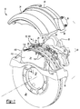
Figure 1 is a partially exploded view of a brake assembly. -
Figure 2 is a section view of a portion of the brake assembly along section line 2-2. -
Figures 3 and 4 are perspective views of a bridge of the brake assembly. - As required, detailed embodiments of the present invention are disclosed herein; however, it is to be understood that the disclosed embodiments are merely exemplary of the invention that may be embodied in various and alternative forms. The figures are not necessarily to scale; some features may be exaggerated or minimized to show details of particular components. Therefore, specific structural and functional details disclosed herein are not to be interpreted as limiting, but merely as a representative basis for teaching one skilled in the art to variously employ the present invention.
- Referring to
Figure 1 , abrake assembly 10 is shown. Thebrake assembly 10 may be provided with a vehicle, such as a motor vehicle like a truck, bus, farm equipment, military transport or weaponry vehicle, or cargo loading equipment for land, air, or marine vessels. In at least one embodiment, thebrake assembly 10 may include ahousing assembly 20, a firstbrake pad assembly 22, a secondbrake pad assembly 24, and at least onebrake pad spring 26. - The
housing assembly 20 may receive various components of thebrake assembly 10. In addition, thehousing assembly 20 may facilitate positioning of the firstbrake pad assembly 22 and the secondbrake pad assembly 24 with respect to arotor 28, also known as a brake disc, to facilitate braking of the vehicle. In at least one embodiment, thehousing assembly 20 may include abrake carrier 30, ahousing 32, and abridge 34. - The
brake carrier 30 may be fixedly mounted to the vehicle. For example, thebrake carrier 30 may be connected to an axle assembly or a steering knuckle, such as with an intermediate component like a torque plate in one or more embodiments. Thebrake carrier 30 may receive and/or support the firstbrake pad assembly 22 and the secondbrake pad assembly 24 and may include a rotor opening that may be configured to receive therotor 28. As such, thebrake carrier 30 may straddle therotor 28 and help position the firstbrake pad assembly 22 and the secondbrake pad assembly 24 on opposite sides of therotor 28. - The
housing 32 may be moveably disposed on thebrake carrier 30. For example, thehousing 32 may be slidably disposed on a pair of guide pins that may be fixedly disposed on thebrake carrier 30. As is best shown inFigure 2 , thehousing 32 may be associated with or may receive at least oneactuator 36 that may actuate the firstbrake pad assembly 22 and the secondbrake pad assembly 24 into engagement with therotor 28. More specifically, theactuator 36 may actuate the firstbrake pad assembly 22 into engagement with therotor 28 and then move thehousing 32 andbridge 34 to actuate the secondbrake pad assembly 24 toward therotor 28. Theactuator 36 may have any suitable configuration. For instance, theactuator 36 may include a piston assembly that may be pneumatically, hydraulically, mechanically, electrically, or electromechanically actuated in one or more embodiments. The piston assembly may move along an axis toward or away from therotor 28 such that the piston assembly may exert force against a back side of the firstbrake pad assembly 22. - Referring to
Figures 2-4 , thebridge 34 may be fixedly disposed on thehousing 32. As such, thebridge 34 may move with thehousing 32 with respect to thebrake carrier 30 when thebrake assembly 10 is actuated. In at least one embodiment, thebridge 34 may include anabutment surface 40, anend surface 42, afirst side surface 44, asecond side surface 46, aninner surface 48, anouter surface 50, asupport bracket 52, amounting stud 54, and amounting stud flange 56. Thebridge 34 may also include three main regions, namely ahousing end region 60, acenter region 62, and anouter end region 64. - The
abutment surface 40 may be disposed proximate and may engage thehousing 32. For example, a portion of theabutment surface 40 that is disposed adjacent to themounting studs 54 may engage thehousing 32 while a portion of theabutment surface 40 that is disposed near the center of thebridge 34 may extend over and may be spaced apart from thehousing 32. Theabutment surface 40 may be substantially planar or may be disposed in a plane in one or more embodiments. - The
end surface 42 may be disposed opposite theabutment surface 40. Theend surface 42 may generally face toward thebrake carrier 30 and may extend along an arc from thefirst side surface 44 to thesecond side surface 46. Theend surface 42 may be spaced apart from the firstbrake pad assembly 22 and the secondbrake pad assembly 24 such that the firstbrake pad assembly 22 and the secondbrake pad assembly 24 may be disposed between thehousing 32 and theend surface 42. - The
first side surface 44 may extend from theabutment surface 40 to theend surface 42. Thefirst side surface 44 may face toward thebrake carrier 30 and may define a portion of the perimeter of thebridge 34. - The
second side surface 46 may be disposed opposite thefirst side surface 44. Thesecond side surface 46 may extend from theabutment surface 40 to theend surface 42. As such, thefirst side surface 44 and thesecond side surface 46 may extend from opposite ends of theabutment surface 40 and from opposite ends of theend surface 42. Thesecond side surface 46 may face toward thebrake carrier 30 and may define a portion of the perimeter of thebridge 34. In addition, thesecond side surface 46 may have substantially the same configuration as thefirst side surface 44. - The
inner surface 48 may face toward thebrake carrier 30, the firstbrake pad assembly 22, and the secondbrake pad assembly 24. Moreover, theinner surface 48 may extend over the firstbrake pad assembly 22, the secondbrake pad assembly 24, and therotor 28. Theinner surface 48 may extend from theabutment surface 40 to theend surface 42 and may extend from thefirst side surface 44 to thesecond side surface 46. In at least one embodiment, theinner surface 48 may extend continuously along an arc from thefirst side surface 44 to thesecond side surface 46. - The
outer surface 50 may be disposed opposite theinner surface 48. As such, theouter surface 50 may face away from thebrake carrier 30. Theouter surface 50 may be disposed substantially parallel to theinner surface 48 in one or more embodiments. - The
bridge 34 may be provided without any openings or through holes that may extend through theinner surface 48 in acenter region 62 that may extend over the firstbrake pad assembly 22 and the secondbrake pad assembly 24. As such, thebridge 34 may not have an opening that may receive a brake pad shield or a retainer bracket, such as may be mounted on thehousing 32 and thebridge 34 to help retain the brake pad shield. Alternatively, thebridge 34 may not have any openings or access holes that are large enough to permit installation or removal of the firstbrake pad assembly 22 or the secondbrake pad assembly 24 through thebridge 34. Such abridge 34 may have greater strength and stiffness as compared to a bridge having an access hole above the brake pad assemblies. Thebridge 34 may also have a reduced thickness and reduced weight as compared to a bridge having an access hole above the brake pad assemblies (which may be configured as a thicker U-shaped cast part that may extend around the brake pad assemblies to provide the access hole). Optionally, thebridge 34 may be provided with a decreased thickness from theinner surface 48 to theouter surface 50 in a region that is disposed above the brake pad assemblies as compared to the perimeter regions of thebridge 34 to help further reduce weight. - Referring to
Figures 2-4 , thesupport bracket 52 may extend from theinner surface 48 and may be disposed proximate the secondbrake pad assembly 24. For instance, thesupport bracket 52 may engage a backing plate of the secondbrake pad assembly 24 to help position and actuate the secondbrake pad assembly 24. Thesupport bracket 52 may have a unitary or one-piece construction and may be fixedly disposed on theinner surface 48. Thesupport bracket 52 may be fixedly disposed on theinner surface 48 in any suitable manner, such as by welding. In at least one embodiment, thesupport bracket 52 may include aninner wall 70, afirst reinforcement flange 72, asecond reinforcement flange 74, anouter wall 76, and a connectingwall 78. - The
inner wall 70 may face toward thehousing 32 and may engage the secondbrake pad assembly 24 and its associatedbrake pad spring 26. Theinner wall 70 may extend from theinner surface 48 and may be disposed substantially perpendicular to theinner surface 48 and substantially parallel to therotor 28. As is best shown inFigure 4 , theinner wall 70 may be spaced apart from theabutment surface 40,end surface 42,first side surface 44, and thesecond side surface 46. - The
first reinforcement flange 72 may extend from theinner surface 48 and may extend from a first end of theinner wall 70 toward thefirst side surface 44. Thefirst reinforcement flange 72 may be offset from theinner wall 70. For example, thefirst reinforcement flange 72 may extend away from thehousing 32 and toward theend surface 42 such that thefirst reinforcement flange 72 may not engage the secondbrake pad assembly 24. - As is best shown in
Figure 4 , thefirst reinforcement flange 72 may include aramp portion 80 and awing portion 82. Theramp portion 80 may extend at an angle from theinner wall 70. For instance, theramp portion 80 may extend away from thehousing 32 and may extend along an arc. Thewing portion 82 may extend from an end of theramp portion 80. As such, theramp portion 80 may extend from theinner wall 70 to thewing portion 82. Thewing portion 82 may extend at an angle from theramp portion 80 and may be disposed substantially parallel to theinner wall 70 in one or more embodiments. In addition, thewing portion 82 may extend toward and may be spaced apart from thefirst side surface 44. Theramp portion 80 and/or thewing portion 82 may extend from and may be attached to theinner surface 48 in one or more embodiments. - The
second reinforcement flange 74 may be disposed opposite thefirst reinforcement flange 72. Thesecond reinforcement flange 74 may extend from theinner surface 48 and may be a mirror image of thefirst reinforcement flange 72. In addition, thesecond reinforcement flange 74 may extend from a second end of theinner wall 70 toward thesecond side surface 46. Thesecond reinforcement flange 74 may be offset from theinner wall 70. For example thesecond reinforcement flange 74 may extend away from thehousing 32 and toward theend surface 42 such that thesecond reinforcement flange 74 may not engage the secondbrake pad assembly 24. - As is best shown in
Figure 4 , thesecond reinforcement flange 74 may include aramp portion 90 and awing portion 92. Theramp portion 90 may extend at an angle from theinner wall 70. For instance, theramp portion 90 may extend away from thehousing 32 and may extend along an arc. Thewing portion 92 may extend from an end of theramp portion 90. As such, theramp portion 90 may extend from theinner wall 70 to thewing portion 92. Thewing portion 92 may extend at an angle from theramp portion 90 and may be disposed substantially parallel to theinner wall 70 in one or more embodiments. In addition, thewing portion 92 may extend toward and may be spaced apart from thesecond side surface 46. Theramp portion 90 and/or thewing portion 92 may extend from and may be attached to theinner surface 48 in one or more embodiments. - Referring to
Figure 2 , theouter wall 76 may be spaced apart from theinner wall 70. Theouter wall 76 may extend from and may be attached to theinner surface 48 and may be disposed between theinner wall 70 and theend surface 42. In addition, theouter wall 76 may not be disposed parallel to theinner wall 70. Theouter wall 76 may have a first end and a second end. The first end may extend from the connectingwall 78. The second end may be disposed opposite the first end and may be disposed proximate theinner surface 48. For instance, the second end may be disposed adjacent to theend surface 42 of thebridge 34. - The connecting
wall 78 may extend between and may connect theinner wall 70 to theouter wall 76. The connectingwall 78 may extend from an end of theinner wall 70 that may be disposed opposite theinner surface 48 to an end of theouter wall 76. In at least one embodiment, the connectingwall 78 may extend along a continuous curve or arc. In addition, the connectingwall 78 may be disposed further from theinner surface 48 than theinner wall 70 and theouter wall 76. - Referring to
Figures 1 and2 , thehousing end region 60 may extend from theabutment surface 40 to thecenter region 62. Thehousing end region 60 may generally extend along an arc and may extend over and may engage an upper surface thehousing 32. Thehousing end region 60 may define anotch 66 that may extend from theabutment surface 40 towards thecenter region 62. Thenotch 66 may receive a portion of thehousing 32 and may not extend to thecenter region 62. - The
center region 62 may be disposed between thehousing end region 60 and theouter end region 64. As such, thecenter region 62 may be disposed between and may be spaced apart from theabutment surface 40 and theend surface 42. Thecenter region 62 may extend continuously from thefirst side surface 44 to thesecond side surface 46 and over the firstbrake pad assembly 22 and the secondbrake pad assembly 24. In addition, thecenter region 62 may have no openings or holes that are large enough to allow a brake pad assembly to be installed on or removed from thebrake assembly 10. Optionally, thecenter region 62 may be provided with a small opening or hole may facilitate visual inspection of the brake pad assemblies and may be fitted with a transparent or semitransparent window to close such an opening or hole. Theinner wall 70 of thesupport bracket 52 may be disposed on thecenter region 62. - The
outer end region 64 may extend from thecenter region 62 to theend surface 42. Theouter end region 64 may extend along an arc from thefirst side surface 44 to thesecond side surface 46 and may also extend along an arc from thecenter region 62 to theend surface 42. Thefirst reinforcement flange 72,second reinforcement flange 74, andouter wall 76 of thesupport bracket 52 may be disposed on theouter end region 64. - Referring to
Figures 3 and 4 , one or more mountingstuds 54 may be provided to facilitate coupling of thebridge 34 to thehousing 32. InFigures 3 and 4 , four mountingstuds 54 are shown; however, it is contemplated that a greater or lesser number of mounting studs may be provided in one or more embodiments. The mountingstuds 54 may extend substantially parallel to each other. Each mountingstud 54 may be received in or may extend through a corresponding hole in thehousing 32. For instance, a mountingstud 54 may extend through a hole in thehousing 32 and may be secured to thehousing 32 with a nut. As such, the mountingstud 54 may enable thebridge 34 to be easily removed from thehousing 32 by removing the nuts, thereby facilitating maintenance of thebrake assembly 10, such as inspection or replacement of the firstbrake pad assembly 22 and the secondbrake pad assembly 24. - A mounting
stud flange 56 may facilitate mounting of a mountingstud 54 to thebridge 34. The mountingstud flange 56 may be disposed on theinner surface 48. The mountingstud 54 may be fixedly disposed on a corresponding mountingstud flange 56 such that each mountingstud 54 may be spaced apart from and may not engage theinner surface 48. - The first
brake pad assembly 22 and the secondbrake pad assembly 24 may be configured to engage opposite sides of therotor 28 to slow the rotation of a vehicle wheel. The firstbrake pad assembly 22 and the secondbrake pad assembly 24 may have similar or identical configurations. In at least one embodiment, the firstbrake pad assembly 22 and the secondbrake pad assembly 24 may each have abacking plate 100 and afriction material 102. - Referring to
Figures 2 and3 , thebacking plate 100 may be a structural member of abrake pad assembly backing plate 100 may be made of any suitable material, such as a metal or metal alloy. In at least one embodiment, thebacking plate 100 may include afirst surface 110, asecond surface 112, and one ormore tabs 114. Thefirst surface 110 may face toward thefriction material 102. Thesecond surface 112 may be disposed opposite thefirst surface 110. One ormore tabs 114 may extend from a top of thebacking plate 100 toward theinner surface 48 of thebridge 34. Thetabs 114 may facilitate positioning of a correspondingbrake pad spring 26. For instance, thetabs 114 may extend through one or more openings in a correspondingbrake pad spring 26. - The
friction material 102 may be disposed on thebacking plate 100. More specifically, thefriction material 102 may be fixedly disposed on thefirst surface 110 of thebacking plate 100. Thefriction material 102 may face toward therotor 28 and may engage therotor 28 during vehicle braking. - A
brake pad spring 26 may be provided with the firstbrake pad assembly 22 and the secondbrake pad assembly 24. For example, a firstbrake pad spring 26 may be disposed between the firstbrake pad assembly 22 and theinner surface 48 of thebridge 34. As such, the firstbrake pad spring 26 may extend from the firstbrake pad assembly 22 to theinner surface 48 and may engage the firstbrake pad assembly 22 and/or theinner surface 48. A secondbrake pad spring 26 may be spaced apart from the firstbrake pad spring 26 and may be disposed between the secondbrake pad assembly 24 and theinner surface 48. As such, the secondbrake pad spring 26 may extend from the secondbrake pad assembly 24 to theinner surface 48 and may engage the secondbrake pad assembly 24 and/or theinner surface 48. Abrake pad spring 26 may exert a biasing force on a corresponding brake pad assembly that may the brake pad assembly against thebrake carrier 30 to help position the brake pad assembly. - The
bridge 34 may be made of a metal alloy and may be primarily manufactured as a stamping rather than a cast part. For example, a sheet of material having a nominal thickness may be provided. A blank may be stamped out of the sheet of material that has the desired shape of thebridge 34. As such, a blank may either be stamped out of the sheet of material to provide the outline or perimeter of thebridge 34 and then the blank may be formed or pressed over a die to provide the desired curvature or the stamping and forming operations may be conducted substantially simultaneously on a common die and press. Thesupport bracket 52 may be stamped and formed separately from the blank for thebridge 34. Next, components of the bridge such as thesupport bracket 52 and the mountingstuds 54 may be attached to the stamped and formed bridge blank to complete thebridge 34. The mountingstuds 54 may be attached to the mountingstud flanges 56 before or after the mountingstud flanges 56 are attached to theinner surface 48 of thebridge 34. The mountingstuds 54 and mountingstud flanges 56 may be attached to theinner surface 48 before, after, or at the same time thesupport bracket 52 is attached to theinner surface 48. - While exemplary embodiments are described above, it is not intended that these embodiments describe all possible forms of the invention. Rather, the words used in the specification are words of description rather than limitation, and it is understood that various changes may be made without departing from the spirit and scope of the invention. Additionally, the features of various implementing embodiments may be combined to form further embodiments of the invention.
Claims (15)
- A brake assembly comprising:a brake carrier that supports first and second brake pad assemblies;first and second brake pad springs disposed on the first and second brake pad assemblies, respectively;a housing disposed on the brake carrier, wherein the housing receives an actuator for actuating the first and second brake pad assemblies; anda bridge that is fixedly disposed on the housing, the bridge including:a first side surface that faces toward the brake carrier;a second side surface that faces toward the brake carrier and is disposed opposite the first side surface;an inner surface that extends from the first side surface to the second side surface and extends over the first and second brake pad assemblies, wherein the first and second pad springs engage the inner surface; anda support bracket that extends from the inner surface, wherein the support bracket engages the second brake pad assembly.
- The brake assembly of claim 1 wherein the inner surface extends continuously along an arc from the first side surface to the second side surface such that no openings are provided in the bridge between the first side surface and the second side surface in a center region that extends over the first and second brake pad assemblies.
- The brake assembly of claim 1 wherein the bridge further comprises an abutment surface disposed proximate the housing and an end surface disposed opposite the abutment surface, wherein the inner surface, the first side surface, and the second side surface extend from the abutment surface to the end surface.
- The brake assembly of claim 1 wherein bridge further comprises a mounting stud that extends from the bridge and couples the bridge to the housing.
- The brake assembly of claim 4 further comprising a mounting stud flange that is disposed on the inner surface, wherein the mounting stud is disposed on the mounting stud flange and extends through a hole in the housing, wherein the mounting stud is spaced apart from and does not engage the inner surface.
- The brake assembly of claim 3 wherein the support bracket includes an inner wall that faces toward the housing and engages the brake pad assembly, wherein the support bracket extends from the inner surface and is spaced apart from the first side surface and the second side surface.
- The brake assembly of claim 6 wherein the support bracket has a first reinforcement flange that extends from a first end of the inner wall toward the first side surface, wherein the first reinforcement flange extends toward the end surface such that the first reinforcement flange does not engage the brake pad assembly, wherein the first reinforcement flange extends from the inner surface.
- The brake assembly of claim 7 wherein the support bracket has a second reinforcement flange that extends from a second end of the inner wall that is disposed opposite the first end toward the second side surface, wherein the second reinforcement flange extends toward the end surface such that the second reinforcement flange does not engage the brake pad assembly wherein the second reinforcement flange extends from the inner surface.
- The brake assembly of claim 7 wherein the support bracket further comprises an outer wall that is spaced apart from the inner wall and a connecting wall that extends from an end of the inner wall that is disposed opposite the inner surface to an end of the outer wall.
- The brake assembly of claim 9 wherein the connecting wall extends along an arc.
- The brake assembly of claim 9 wherein the outer wall extends from the inner surface.
- The brake assembly of claim 9 wherein the outer wall is disposed between the inner wall and the end surface.
- The brake assembly of claim 9 wherein the connecting wall is disposed further from the inner surface than the inner wall and the outer wall.
- The brake assembly of claim 9 wherein the first reinforcement flange is disposed further from the housing than the connecting wall.
- The brake assembly of claim 9 wherein the outer wall is disposed adjacent to the end surface of the bridge.
Applications Claiming Priority (1)
| Application Number | Priority Date | Filing Date | Title |
|---|---|---|---|
| US14/860,101 US9920800B2 (en) | 2015-09-21 | 2015-09-21 | Brake assembly having a bridge |
Publications (2)
| Publication Number | Publication Date |
|---|---|
| EP3150878A1 true EP3150878A1 (en) | 2017-04-05 |
| EP3150878B1 EP3150878B1 (en) | 2020-09-23 |
Family
ID=56344998
Family Applications (1)
| Application Number | Title | Priority Date | Filing Date |
|---|---|---|---|
| EP16176730.6A Not-in-force EP3150878B1 (en) | 2015-09-21 | 2016-06-28 | Brake assembly having a bridge |
Country Status (4)
| Country | Link |
|---|---|
| US (1) | US9920800B2 (en) |
| EP (1) | EP3150878B1 (en) |
| CN (1) | CN106545601B (en) |
| BR (1) | BR102016016286B1 (en) |
Families Citing this family (4)
| Publication number | Priority date | Publication date | Assignee | Title |
|---|---|---|---|---|
| US10400837B2 (en) | 2017-10-11 | 2019-09-03 | Arvinmeritor Technology, Llc | Brake carrier and method of manufacture |
| US10487892B2 (en) | 2018-03-02 | 2019-11-26 | Arvinmeritor Technology, Llc | Brake caliper housing method of manufacture |
| US20190271367A1 (en) * | 2018-03-02 | 2019-09-05 | Arvinmeritor Technology, Llc | Brake assembly having a bridge |
| EP3546784A1 (en) * | 2018-03-28 | 2019-10-02 | Meritor Heavy Vehicle Braking Systems (UK) Limited | Brake assembly |
Citations (3)
| Publication number | Priority date | Publication date | Assignee | Title |
|---|---|---|---|---|
| US8857575B2 (en) | 2012-12-11 | 2014-10-14 | Arvinmeritor Technology, Llc | Brake caliper assembly having a pad shield |
| US20150184710A1 (en) * | 2012-09-17 | 2015-07-02 | Knorr-Bremse Systeme Fuer Nutzfahrzeuge Gmbh | Arrangement of a Pad Retaining Clip on the Brake Caliper of a Disc Brake, and Brake Pad |
| DE102014107227A1 (en) * | 2014-03-14 | 2015-09-17 | Knorr-Bremse Systeme für Nutzfahrzeuge GmbH | Disc brake with pad retainer and safety device, and brake pad set |
Family Cites Families (16)
| Publication number | Priority date | Publication date | Assignee | Title |
|---|---|---|---|---|
| WO1993003290A1 (en) * | 1991-08-07 | 1993-02-18 | Brake And Clutch Industries Australia Pty. Ltd. | Disc brake caliper and method of making same |
| DE4236683C2 (en) * | 1992-10-30 | 2003-07-24 | Continental Teves Ag & Co Ohg | Floating caliper-type disc brake |
| US5727659A (en) * | 1996-10-03 | 1998-03-17 | Hayes Industrial Brake, Inc. | Die cast disc brake with a vibration dampering flat spring |
| US6223863B1 (en) * | 1996-12-12 | 2001-05-01 | Federal-Mogul Technology Limited | Disc brake suspension for improved turning circle |
| US5875873A (en) * | 1997-05-05 | 1999-03-02 | Meritor Heavy Vehicle Systems, Llc | Air disc brake anti-rattle design |
| AUPP995099A0 (en) * | 1999-04-26 | 1999-05-20 | Pbr Automotive Pty Ltd | Disc brake caliper |
| US6302243B1 (en) * | 1999-10-29 | 2001-10-16 | Stoptech Technologies Llc | Stiffening bracket for brake calipers |
| SE0203442L (en) * | 2002-11-21 | 2003-10-28 | Scania Cv Abp | Protective cover for disc brake and disc brake unit including such protective cover unit |
| GB0322910D0 (en) * | 2003-09-30 | 2003-11-05 | Meritor Heavy Vehicle Braking | Brake caliper and brake pad |
| DE102007006472A1 (en) * | 2006-04-20 | 2007-11-08 | Continental Teves Ag & Co. Ohg | Disk brake for motor vehicle, has central supports with radial wall thickness that is designed such that spacing between central supports and rotational axis of brake disk is smaller than outer radius of disk, in axial region of linings |
| DE102006033159A1 (en) * | 2006-07-18 | 2008-01-24 | Dr.Ing.H.C. F. Porsche Ag | Brake caliper for a disc brake of a motor vehicle |
| DE102006039298B3 (en) * | 2006-08-22 | 2008-04-10 | Knorr-Bremse Systeme für Nutzfahrzeuge GmbH | Disc brake, in particular for a commercial vehicle |
| US20080110707A1 (en) * | 2006-11-15 | 2008-05-15 | Bendix Spicer Foundation Brake Llc | Pad shield |
| DE102008038035A1 (en) * | 2008-08-16 | 2010-02-18 | Dr.Ing.H.C.F.Porsche Aktiengesellschaft | Brake caliper and related manufacturing process |
| JP2010127326A (en) * | 2008-11-26 | 2010-06-10 | Akebono Brake Ind Co Ltd | Floating caliper type disk brake |
| US8485323B2 (en) * | 2010-10-08 | 2013-07-16 | Akebono Brake Corporation | Caliper assembly for disc brake system |
-
2015
- 2015-09-21 US US14/860,101 patent/US9920800B2/en active Active
-
2016
- 2016-03-28 CN CN201610182705.9A patent/CN106545601B/en active Active
- 2016-06-28 EP EP16176730.6A patent/EP3150878B1/en not_active Not-in-force
- 2016-07-13 BR BR102016016286-6A patent/BR102016016286B1/en not_active IP Right Cessation
Patent Citations (3)
| Publication number | Priority date | Publication date | Assignee | Title |
|---|---|---|---|---|
| US20150184710A1 (en) * | 2012-09-17 | 2015-07-02 | Knorr-Bremse Systeme Fuer Nutzfahrzeuge Gmbh | Arrangement of a Pad Retaining Clip on the Brake Caliper of a Disc Brake, and Brake Pad |
| US8857575B2 (en) | 2012-12-11 | 2014-10-14 | Arvinmeritor Technology, Llc | Brake caliper assembly having a pad shield |
| DE102014107227A1 (en) * | 2014-03-14 | 2015-09-17 | Knorr-Bremse Systeme für Nutzfahrzeuge GmbH | Disc brake with pad retainer and safety device, and brake pad set |
Also Published As
| Publication number | Publication date |
|---|---|
| US20170082160A1 (en) | 2017-03-23 |
| CN106545601B (en) | 2018-11-30 |
| EP3150878B1 (en) | 2020-09-23 |
| BR102016016286B1 (en) | 2023-04-18 |
| US9920800B2 (en) | 2018-03-20 |
| BR102016016286A2 (en) | 2017-07-25 |
| CN106545601A (en) | 2017-03-29 |
Similar Documents
| Publication | Publication Date | Title |
|---|---|---|
| EP2743533B1 (en) | Brake calliper assembly having a pad shield | |
| EP3150878B1 (en) | Brake assembly having a bridge | |
| EP3033540B1 (en) | Brake disc for a vehicle | |
| EP3865726B1 (en) | Brake assembly having a retraction spring | |
| EP3534030B1 (en) | Brake caliper assembly having a retainer bracket | |
| EP2392835A2 (en) | Disc brake | |
| US7849982B1 (en) | Garnish plate mounting structure | |
| US10160275B2 (en) | Suspension member for a motor vehicle and method of making same | |
| CN103921619B (en) | Drum guiding wheel hub | |
| EP3210804A2 (en) | Axle suspension system having an axle wrap and method of manufacture | |
| US10781875B2 (en) | Disc brake | |
| EP3534029A1 (en) | Brake assembly having a bridge | |
| CA2920736C (en) | Heavy duty stamped spider | |
| EP3032125B1 (en) | Disc brake and components thereof | |
| US20180347649A1 (en) | Disc brake | |
| CN108369430A (en) | Operating pedal device for vehicle | |
| CN112392875B (en) | Disc brake | |
| US10724585B2 (en) | Brake pad | |
| EP3772600A1 (en) | Brake assembly having an actuator mount | |
| EP3572252A1 (en) | Support beam | |
| DE102016204607A1 (en) | Motor vehicle fixed caliper brake with a carrier made of formed sheet steel material | |
| DE10352141A1 (en) | High performance disc brake with versatile assembly has selected spacer blocks linking two outer housings with at least one of the housings with mountings to fit into different vehicles | |
| EP3499075A1 (en) | A brake housing assembly | |
| DE102013016203A1 (en) | Electromotive valve actuator |
Legal Events
| Date | Code | Title | Description |
|---|---|---|---|
| PUAI | Public reference made under article 153(3) epc to a published international application that has entered the european phase |
Free format text: ORIGINAL CODE: 0009012 |
|
| STAA | Information on the status of an ep patent application or granted ep patent |
Free format text: STATUS: THE APPLICATION HAS BEEN PUBLISHED |
|
| AK | Designated contracting states |
Kind code of ref document: A1 Designated state(s): AL AT BE BG CH CY CZ DE DK EE ES FI FR GB GR HR HU IE IS IT LI LT LU LV MC MK MT NL NO PL PT RO RS SE SI SK SM TR |
|
| AX | Request for extension of the european patent |
Extension state: BA ME |
|
| STAA | Information on the status of an ep patent application or granted ep patent |
Free format text: STATUS: REQUEST FOR EXAMINATION WAS MADE |
|
| 17P | Request for examination filed |
Effective date: 20171005 |
|
| RBV | Designated contracting states (corrected) |
Designated state(s): AL AT BE BG CH CY CZ DE DK EE ES FI FR GB GR HR HU IE IS IT LI LT LU LV MC MK MT NL NO PL PT RO RS SE SI SK SM TR |
|
| STAA | Information on the status of an ep patent application or granted ep patent |
Free format text: STATUS: EXAMINATION IS IN PROGRESS |
|
| 17Q | First examination report despatched |
Effective date: 20190709 |
|
| GRAP | Despatch of communication of intention to grant a patent |
Free format text: ORIGINAL CODE: EPIDOSNIGR1 |
|
| STAA | Information on the status of an ep patent application or granted ep patent |
Free format text: STATUS: GRANT OF PATENT IS INTENDED |
|
| INTG | Intention to grant announced |
Effective date: 20200414 |
|
| GRAS | Grant fee paid |
Free format text: ORIGINAL CODE: EPIDOSNIGR3 |
|
| GRAA | (expected) grant |
Free format text: ORIGINAL CODE: 0009210 |
|
| STAA | Information on the status of an ep patent application or granted ep patent |
Free format text: STATUS: THE PATENT HAS BEEN GRANTED |
|
| AK | Designated contracting states |
Kind code of ref document: B1 Designated state(s): AL AT BE BG CH CY CZ DE DK EE ES FI FR GB GR HR HU IE IS IT LI LT LU LV MC MK MT NL NO PL PT RO RS SE SI SK SM TR |
|
| REG | Reference to a national code |
Ref country code: GB Ref legal event code: FG4D |
|
| REG | Reference to a national code |
Ref country code: CH Ref legal event code: EP |
|
| REG | Reference to a national code |
Ref country code: IE Ref legal event code: FG4D |
|
| REG | Reference to a national code |
Ref country code: DE Ref legal event code: R096 Ref document number: 602016044413 Country of ref document: DE Ref country code: AT Ref legal event code: REF Ref document number: 1316675 Country of ref document: AT Kind code of ref document: T Effective date: 20201015 |
|
| PG25 | Lapsed in a contracting state [announced via postgrant information from national office to epo] |
Ref country code: BG Free format text: LAPSE BECAUSE OF FAILURE TO SUBMIT A TRANSLATION OF THE DESCRIPTION OR TO PAY THE FEE WITHIN THE PRESCRIBED TIME-LIMIT Effective date: 20201223 Ref country code: GR Free format text: LAPSE BECAUSE OF FAILURE TO SUBMIT A TRANSLATION OF THE DESCRIPTION OR TO PAY THE FEE WITHIN THE PRESCRIBED TIME-LIMIT Effective date: 20201224 Ref country code: HR Free format text: LAPSE BECAUSE OF FAILURE TO SUBMIT A TRANSLATION OF THE DESCRIPTION OR TO PAY THE FEE WITHIN THE PRESCRIBED TIME-LIMIT Effective date: 20200923 Ref country code: FI Free format text: LAPSE BECAUSE OF FAILURE TO SUBMIT A TRANSLATION OF THE DESCRIPTION OR TO PAY THE FEE WITHIN THE PRESCRIBED TIME-LIMIT Effective date: 20200923 Ref country code: NO Free format text: LAPSE BECAUSE OF FAILURE TO SUBMIT A TRANSLATION OF THE DESCRIPTION OR TO PAY THE FEE WITHIN THE PRESCRIBED TIME-LIMIT Effective date: 20201223 |
|
| REG | Reference to a national code |
Ref country code: AT Ref legal event code: MK05 Ref document number: 1316675 Country of ref document: AT Kind code of ref document: T Effective date: 20200923 |
|
| PG25 | Lapsed in a contracting state [announced via postgrant information from national office to epo] |
Ref country code: LV Free format text: LAPSE BECAUSE OF FAILURE TO SUBMIT A TRANSLATION OF THE DESCRIPTION OR TO PAY THE FEE WITHIN THE PRESCRIBED TIME-LIMIT Effective date: 20200923 Ref country code: RS Free format text: LAPSE BECAUSE OF FAILURE TO SUBMIT A TRANSLATION OF THE DESCRIPTION OR TO PAY THE FEE WITHIN THE PRESCRIBED TIME-LIMIT Effective date: 20200923 |
|
| REG | Reference to a national code |
Ref country code: NL Ref legal event code: MP Effective date: 20200923 |
|
| REG | Reference to a national code |
Ref country code: LT Ref legal event code: MG4D |
|
| PG25 | Lapsed in a contracting state [announced via postgrant information from national office to epo] |
Ref country code: EE Free format text: LAPSE BECAUSE OF FAILURE TO SUBMIT A TRANSLATION OF THE DESCRIPTION OR TO PAY THE FEE WITHIN THE PRESCRIBED TIME-LIMIT Effective date: 20200923 Ref country code: CZ Free format text: LAPSE BECAUSE OF FAILURE TO SUBMIT A TRANSLATION OF THE DESCRIPTION OR TO PAY THE FEE WITHIN THE PRESCRIBED TIME-LIMIT Effective date: 20200923 Ref country code: SM Free format text: LAPSE BECAUSE OF FAILURE TO SUBMIT A TRANSLATION OF THE DESCRIPTION OR TO PAY THE FEE WITHIN THE PRESCRIBED TIME-LIMIT Effective date: 20200923 Ref country code: PT Free format text: LAPSE BECAUSE OF FAILURE TO SUBMIT A TRANSLATION OF THE DESCRIPTION OR TO PAY THE FEE WITHIN THE PRESCRIBED TIME-LIMIT Effective date: 20210125 Ref country code: RO Free format text: LAPSE BECAUSE OF FAILURE TO SUBMIT A TRANSLATION OF THE DESCRIPTION OR TO PAY THE FEE WITHIN THE PRESCRIBED TIME-LIMIT Effective date: 20200923 Ref country code: NL Free format text: LAPSE BECAUSE OF FAILURE TO SUBMIT A TRANSLATION OF THE DESCRIPTION OR TO PAY THE FEE WITHIN THE PRESCRIBED TIME-LIMIT Effective date: 20200923 Ref country code: LT Free format text: LAPSE BECAUSE OF FAILURE TO SUBMIT A TRANSLATION OF THE DESCRIPTION OR TO PAY THE FEE WITHIN THE PRESCRIBED TIME-LIMIT Effective date: 20200923 |
|
| PG25 | Lapsed in a contracting state [announced via postgrant information from national office to epo] |
Ref country code: AT Free format text: LAPSE BECAUSE OF FAILURE TO SUBMIT A TRANSLATION OF THE DESCRIPTION OR TO PAY THE FEE WITHIN THE PRESCRIBED TIME-LIMIT Effective date: 20200923 Ref country code: AL Free format text: LAPSE BECAUSE OF FAILURE TO SUBMIT A TRANSLATION OF THE DESCRIPTION OR TO PAY THE FEE WITHIN THE PRESCRIBED TIME-LIMIT Effective date: 20200923 Ref country code: ES Free format text: LAPSE BECAUSE OF FAILURE TO SUBMIT A TRANSLATION OF THE DESCRIPTION OR TO PAY THE FEE WITHIN THE PRESCRIBED TIME-LIMIT Effective date: 20200923 Ref country code: PL Free format text: LAPSE BECAUSE OF FAILURE TO SUBMIT A TRANSLATION OF THE DESCRIPTION OR TO PAY THE FEE WITHIN THE PRESCRIBED TIME-LIMIT Effective date: 20200923 Ref country code: IS Free format text: LAPSE BECAUSE OF FAILURE TO SUBMIT A TRANSLATION OF THE DESCRIPTION OR TO PAY THE FEE WITHIN THE PRESCRIBED TIME-LIMIT Effective date: 20210123 |
|
| REG | Reference to a national code |
Ref country code: DE Ref legal event code: R097 Ref document number: 602016044413 Country of ref document: DE |
|
| PG25 | Lapsed in a contracting state [announced via postgrant information from national office to epo] |
Ref country code: SK Free format text: LAPSE BECAUSE OF FAILURE TO SUBMIT A TRANSLATION OF THE DESCRIPTION OR TO PAY THE FEE WITHIN THE PRESCRIBED TIME-LIMIT Effective date: 20200923 |
|
| PLBE | No opposition filed within time limit |
Free format text: ORIGINAL CODE: 0009261 |
|
| STAA | Information on the status of an ep patent application or granted ep patent |
Free format text: STATUS: NO OPPOSITION FILED WITHIN TIME LIMIT |
|
| PG25 | Lapsed in a contracting state [announced via postgrant information from national office to epo] |
Ref country code: SI Free format text: LAPSE BECAUSE OF FAILURE TO SUBMIT A TRANSLATION OF THE DESCRIPTION OR TO PAY THE FEE WITHIN THE PRESCRIBED TIME-LIMIT Effective date: 20200923 Ref country code: DK Free format text: LAPSE BECAUSE OF FAILURE TO SUBMIT A TRANSLATION OF THE DESCRIPTION OR TO PAY THE FEE WITHIN THE PRESCRIBED TIME-LIMIT Effective date: 20200923 |
|
| 26N | No opposition filed |
Effective date: 20210624 |
|
| PG25 | Lapsed in a contracting state [announced via postgrant information from national office to epo] |
Ref country code: IT Free format text: LAPSE BECAUSE OF FAILURE TO SUBMIT A TRANSLATION OF THE DESCRIPTION OR TO PAY THE FEE WITHIN THE PRESCRIBED TIME-LIMIT Effective date: 20200923 |
|
| PG25 | Lapsed in a contracting state [announced via postgrant information from national office to epo] |
Ref country code: MC Free format text: LAPSE BECAUSE OF FAILURE TO SUBMIT A TRANSLATION OF THE DESCRIPTION OR TO PAY THE FEE WITHIN THE PRESCRIBED TIME-LIMIT Effective date: 20200923 |
|
| REG | Reference to a national code |
Ref country code: CH Ref legal event code: PL |
|
| GBPC | Gb: european patent ceased through non-payment of renewal fee |
Effective date: 20210628 |
|
| REG | Reference to a national code |
Ref country code: BE Ref legal event code: MM Effective date: 20210630 |
|
| PG25 | Lapsed in a contracting state [announced via postgrant information from national office to epo] |
Ref country code: LU Free format text: LAPSE BECAUSE OF NON-PAYMENT OF DUE FEES Effective date: 20210628 |
|
| PG25 | Lapsed in a contracting state [announced via postgrant information from national office to epo] |
Ref country code: LI Free format text: LAPSE BECAUSE OF NON-PAYMENT OF DUE FEES Effective date: 20210630 Ref country code: IE Free format text: LAPSE BECAUSE OF NON-PAYMENT OF DUE FEES Effective date: 20210628 Ref country code: GB Free format text: LAPSE BECAUSE OF NON-PAYMENT OF DUE FEES Effective date: 20210628 Ref country code: CH Free format text: LAPSE BECAUSE OF NON-PAYMENT OF DUE FEES Effective date: 20210630 |
|
| PG25 | Lapsed in a contracting state [announced via postgrant information from national office to epo] |
Ref country code: BE Free format text: LAPSE BECAUSE OF NON-PAYMENT OF DUE FEES Effective date: 20210630 |
|
| PGFP | Annual fee paid to national office [announced via postgrant information from national office to epo] |
Ref country code: SE Payment date: 20220627 Year of fee payment: 7 |
|
| PGFP | Annual fee paid to national office [announced via postgrant information from national office to epo] |
Ref country code: FR Payment date: 20220627 Year of fee payment: 7 |
|
| PG25 | Lapsed in a contracting state [announced via postgrant information from national office to epo] |
Ref country code: HU Free format text: LAPSE BECAUSE OF FAILURE TO SUBMIT A TRANSLATION OF THE DESCRIPTION OR TO PAY THE FEE WITHIN THE PRESCRIBED TIME-LIMIT; INVALID AB INITIO Effective date: 20160628 |
|
| PG25 | Lapsed in a contracting state [announced via postgrant information from national office to epo] |
Ref country code: CY Free format text: LAPSE BECAUSE OF FAILURE TO SUBMIT A TRANSLATION OF THE DESCRIPTION OR TO PAY THE FEE WITHIN THE PRESCRIBED TIME-LIMIT Effective date: 20200923 |
|
| REG | Reference to a national code |
Ref country code: SE Ref legal event code: EUG |
|
| PG25 | Lapsed in a contracting state [announced via postgrant information from national office to epo] |
Ref country code: MK Free format text: LAPSE BECAUSE OF FAILURE TO SUBMIT A TRANSLATION OF THE DESCRIPTION OR TO PAY THE FEE WITHIN THE PRESCRIBED TIME-LIMIT Effective date: 20200923 |
|
| PG25 | Lapsed in a contracting state [announced via postgrant information from national office to epo] |
Ref country code: SE Free format text: LAPSE BECAUSE OF NON-PAYMENT OF DUE FEES Effective date: 20230629 Ref country code: FR Free format text: LAPSE BECAUSE OF NON-PAYMENT OF DUE FEES Effective date: 20230630 |
|
| PGFP | Annual fee paid to national office [announced via postgrant information from national office to epo] |
Ref country code: DE Payment date: 20240627 Year of fee payment: 9 |
|
| PG25 | Lapsed in a contracting state [announced via postgrant information from national office to epo] |
Ref country code: MT Free format text: LAPSE BECAUSE OF FAILURE TO SUBMIT A TRANSLATION OF THE DESCRIPTION OR TO PAY THE FEE WITHIN THE PRESCRIBED TIME-LIMIT Effective date: 20200923 |
|
| PG25 | Lapsed in a contracting state [announced via postgrant information from national office to epo] |
Ref country code: TR Free format text: LAPSE BECAUSE OF FAILURE TO SUBMIT A TRANSLATION OF THE DESCRIPTION OR TO PAY THE FEE WITHIN THE PRESCRIBED TIME-LIMIT Effective date: 20200923 |
|
| REG | Reference to a national code |
Ref country code: DE Ref legal event code: R119 Ref document number: 602016044413 Country of ref document: DE |
|
| PG25 | Lapsed in a contracting state [announced via postgrant information from national office to epo] |
Ref country code: DE Free format text: LAPSE BECAUSE OF NON-PAYMENT OF DUE FEES Effective date: 20260101 |