EP3150452B1 - Test of a function for controlling the trajectory of a vehicle using the brakes without controlling the steering wheel - Google Patents
Test of a function for controlling the trajectory of a vehicle using the brakes without controlling the steering wheel Download PDFInfo
- Publication number
- EP3150452B1 EP3150452B1 EP16186848.4A EP16186848A EP3150452B1 EP 3150452 B1 EP3150452 B1 EP 3150452B1 EP 16186848 A EP16186848 A EP 16186848A EP 3150452 B1 EP3150452 B1 EP 3150452B1
- Authority
- EP
- European Patent Office
- Prior art keywords
- vehicle
- steering
- fact
- wheel
- trajectory
- Prior art date
- Legal status (The legal status is an assumption and is not a legal conclusion. Google has not performed a legal analysis and makes no representation as to the accuracy of the status listed.)
- Active
Links
- 238000012360 testing method Methods 0.000 title claims description 17
- 238000010998 test method Methods 0.000 claims description 19
- 238000000034 method Methods 0.000 claims description 18
- 230000000694 effects Effects 0.000 claims description 13
- 230000009471 action Effects 0.000 claims description 5
- 230000001960 triggered effect Effects 0.000 claims description 2
- 230000006870 function Effects 0.000 description 14
- 238000010586 diagram Methods 0.000 description 5
- 230000005484 gravity Effects 0.000 description 4
- 230000001133 acceleration Effects 0.000 description 3
- 238000012937 correction Methods 0.000 description 3
- 230000008901 benefit Effects 0.000 description 2
- 230000001419 dependent effect Effects 0.000 description 2
- 238000012986 modification Methods 0.000 description 2
- 230000004048 modification Effects 0.000 description 2
- 230000004044 response Effects 0.000 description 2
- 102100034112 Alkyldihydroxyacetonephosphate synthase, peroxisomal Human genes 0.000 description 1
- 101000799143 Homo sapiens Alkyldihydroxyacetonephosphate synthase, peroxisomal Proteins 0.000 description 1
- XAGFODPZIPBFFR-UHFFFAOYSA-N aluminium Chemical compound [Al] XAGFODPZIPBFFR-UHFFFAOYSA-N 0.000 description 1
- 229910052782 aluminium Inorganic materials 0.000 description 1
- 238000000848 angular dependent Auger electron spectroscopy Methods 0.000 description 1
- 230000008859 change Effects 0.000 description 1
- 238000006243 chemical reaction Methods 0.000 description 1
- 230000003247 decreasing effect Effects 0.000 description 1
- 238000006073 displacement reaction Methods 0.000 description 1
- 238000012423 maintenance Methods 0.000 description 1
- 230000008092 positive effect Effects 0.000 description 1
- 230000008569 process Effects 0.000 description 1
- 230000004043 responsiveness Effects 0.000 description 1
- 238000005096 rolling process Methods 0.000 description 1
- 230000000087 stabilizing effect Effects 0.000 description 1
- 230000001502 supplementing effect Effects 0.000 description 1
- 238000012546 transfer Methods 0.000 description 1
Images


Classifications
-
- B—PERFORMING OPERATIONS; TRANSPORTING
- B60—VEHICLES IN GENERAL
- B60W—CONJOINT CONTROL OF VEHICLE SUB-UNITS OF DIFFERENT TYPE OR DIFFERENT FUNCTION; CONTROL SYSTEMS SPECIALLY ADAPTED FOR HYBRID VEHICLES; ROAD VEHICLE DRIVE CONTROL SYSTEMS FOR PURPOSES NOT RELATED TO THE CONTROL OF A PARTICULAR SUB-UNIT
- B60W10/00—Conjoint control of vehicle sub-units of different type or different function
- B60W10/18—Conjoint control of vehicle sub-units of different type or different function including control of braking systems
-
- B—PERFORMING OPERATIONS; TRANSPORTING
- B60—VEHICLES IN GENERAL
- B60W—CONJOINT CONTROL OF VEHICLE SUB-UNITS OF DIFFERENT TYPE OR DIFFERENT FUNCTION; CONTROL SYSTEMS SPECIALLY ADAPTED FOR HYBRID VEHICLES; ROAD VEHICLE DRIVE CONTROL SYSTEMS FOR PURPOSES NOT RELATED TO THE CONTROL OF A PARTICULAR SUB-UNIT
- B60W10/00—Conjoint control of vehicle sub-units of different type or different function
- B60W10/20—Conjoint control of vehicle sub-units of different type or different function including control of steering systems
-
- B—PERFORMING OPERATIONS; TRANSPORTING
- B60—VEHICLES IN GENERAL
- B60W—CONJOINT CONTROL OF VEHICLE SUB-UNITS OF DIFFERENT TYPE OR DIFFERENT FUNCTION; CONTROL SYSTEMS SPECIALLY ADAPTED FOR HYBRID VEHICLES; ROAD VEHICLE DRIVE CONTROL SYSTEMS FOR PURPOSES NOT RELATED TO THE CONTROL OF A PARTICULAR SUB-UNIT
- B60W50/00—Details of control systems for road vehicle drive control not related to the control of a particular sub-unit, e.g. process diagnostic or vehicle driver interfaces
- B60W50/02—Ensuring safety in case of control system failures, e.g. by diagnosing, circumventing or fixing failures
- B60W50/0205—Diagnosing or detecting failures; Failure detection models
-
- B—PERFORMING OPERATIONS; TRANSPORTING
- B60—VEHICLES IN GENERAL
- B60W—CONJOINT CONTROL OF VEHICLE SUB-UNITS OF DIFFERENT TYPE OR DIFFERENT FUNCTION; CONTROL SYSTEMS SPECIALLY ADAPTED FOR HYBRID VEHICLES; ROAD VEHICLE DRIVE CONTROL SYSTEMS FOR PURPOSES NOT RELATED TO THE CONTROL OF A PARTICULAR SUB-UNIT
- B60W50/00—Details of control systems for road vehicle drive control not related to the control of a particular sub-unit, e.g. process diagnostic or vehicle driver interfaces
- B60W50/02—Ensuring safety in case of control system failures, e.g. by diagnosing, circumventing or fixing failures
- B60W50/0225—Failure correction strategy
-
- B—PERFORMING OPERATIONS; TRANSPORTING
- B60—VEHICLES IN GENERAL
- B60W—CONJOINT CONTROL OF VEHICLE SUB-UNITS OF DIFFERENT TYPE OR DIFFERENT FUNCTION; CONTROL SYSTEMS SPECIALLY ADAPTED FOR HYBRID VEHICLES; ROAD VEHICLE DRIVE CONTROL SYSTEMS FOR PURPOSES NOT RELATED TO THE CONTROL OF A PARTICULAR SUB-UNIT
- B60W50/00—Details of control systems for road vehicle drive control not related to the control of a particular sub-unit, e.g. process diagnostic or vehicle driver interfaces
- B60W50/02—Ensuring safety in case of control system failures, e.g. by diagnosing, circumventing or fixing failures
- B60W50/029—Adapting to failures or work around with other constraints, e.g. circumvention by avoiding use of failed parts
-
- B—PERFORMING OPERATIONS; TRANSPORTING
- B62—LAND VEHICLES FOR TRAVELLING OTHERWISE THAN ON RAILS
- B62D—MOTOR VEHICLES; TRAILERS
- B62D9/00—Steering deflectable wheels not otherwise provided for
- B62D9/005—Emergency systems using brakes for steering
-
- B—PERFORMING OPERATIONS; TRANSPORTING
- B60—VEHICLES IN GENERAL
- B60W—CONJOINT CONTROL OF VEHICLE SUB-UNITS OF DIFFERENT TYPE OR DIFFERENT FUNCTION; CONTROL SYSTEMS SPECIALLY ADAPTED FOR HYBRID VEHICLES; ROAD VEHICLE DRIVE CONTROL SYSTEMS FOR PURPOSES NOT RELATED TO THE CONTROL OF A PARTICULAR SUB-UNIT
- B60W50/00—Details of control systems for road vehicle drive control not related to the control of a particular sub-unit, e.g. process diagnostic or vehicle driver interfaces
- B60W2050/0062—Adapting control system settings
- B60W2050/0075—Automatic parameter input, automatic initialising or calibrating means
- B60W2050/0083—Setting, resetting, calibration
- B60W2050/0086—Recalibrating datum positions, e.g. by using check cycles
-
- B—PERFORMING OPERATIONS; TRANSPORTING
- B60—VEHICLES IN GENERAL
- B60W—CONJOINT CONTROL OF VEHICLE SUB-UNITS OF DIFFERENT TYPE OR DIFFERENT FUNCTION; CONTROL SYSTEMS SPECIALLY ADAPTED FOR HYBRID VEHICLES; ROAD VEHICLE DRIVE CONTROL SYSTEMS FOR PURPOSES NOT RELATED TO THE CONTROL OF A PARTICULAR SUB-UNIT
- B60W50/00—Details of control systems for road vehicle drive control not related to the control of a particular sub-unit, e.g. process diagnostic or vehicle driver interfaces
- B60W50/02—Ensuring safety in case of control system failures, e.g. by diagnosing, circumventing or fixing failures
- B60W50/029—Adapting to failures or work around with other constraints, e.g. circumvention by avoiding use of failed parts
- B60W2050/0297—Control Giving priority to different actuators or systems
-
- B—PERFORMING OPERATIONS; TRANSPORTING
- B60—VEHICLES IN GENERAL
- B60W—CONJOINT CONTROL OF VEHICLE SUB-UNITS OF DIFFERENT TYPE OR DIFFERENT FUNCTION; CONTROL SYSTEMS SPECIALLY ADAPTED FOR HYBRID VEHICLES; ROAD VEHICLE DRIVE CONTROL SYSTEMS FOR PURPOSES NOT RELATED TO THE CONTROL OF A PARTICULAR SUB-UNIT
- B60W2720/00—Output or target parameters relating to overall vehicle dynamics
- B60W2720/14—Yaw
Definitions
- the present invention relates to a method of controlling the trajectory of a motor vehicle with the wheel brakes in the absence of steering control, and a motor vehicle equipped with means implementing such a method.
- Motor vehicles generally comprise a steering system comprising a steering wheel driving by a steering column a housing located at its base, which transmits on each side of the vehicle a transverse movement to a rod equipped with ball joints at its ends.
- the housing may comprise a rack arranged transversely.
- the front axle of the vehicle comprises on each side a hub carrier pivotable about a substantially vertical pivot axis disposed near the center of the wheel, which receives the transverse movement of the link to rotate the wheel about the axis. pivot and provide direction.
- the steering systems can be equipped with an assistance using electric or hydraulic energy, which delivers on the steering box a part of the torque necessary for steering wheel steering, supplementing the one provided by the driver.
- the vehicles may be equipped with a driving assistance system for the electronic stability program called ESP (Electronic Stability Program), which has a self-contained source of hydraulic pressure, which, based on information on the trajectory followed by the vehicle given by different sensors, compared to that requested by the driver operating the steering wheel, acts automatically on some wheel brakes to generate a yaw moment around the vertical axis passing through the direction of gravity of the vehicle. The vehicle is thus pivoted in order to restore the desired trajectory if the driver assistance system detects a drift.
- ESP Electronic Stability Program
- a method of stabilizing the known vehicle uses an ESP type track control system to provide steering for the vehicle.
- Another known method of trajectory control in the event of failure of the steering system comprises applying to the differential of the vehicle's front end, a braking torque on the inside of the turn and a driving torque on the outside, to generate on the front wheels a difference in longitudinal force ensuring the direction of the vehicle.
- the particular geometry of the direction of the vehicle can also generate torque on the steering of each front wheel causing a rotation of the steering wheel, this steering adding to the moment of yaw from the longitudinal braking forces of the wheels .
- the geometry of the direction of the vehicle can change, especially in the case of wheel changes, for example by installing tires for a season with rims with different dimensions.
- the present invention is intended to avoid these disadvantages of the prior art.
- An advantage of this control method is that the test performed periodically makes it possible to know in a simple, effective and precise manner the effect on the steering of a braking of a front wheel from the real state of the vehicle, taking into account This includes recent changes to this vehicle such as front wheel modifications.
- the method can then directly establish the optimum braking pressures of the different wheels taking into account the torque on the steering wheel given by the actual geometry of the steering.
- the trajectory control method according to the invention may further comprise one or more of the following features, which may be combined with each other.
- the test method applies substantially the maximum possible braking of the front wheel, within the limit of the adhesion of the wheels.
- the test method requires a test periodically.
- the update of the piloting values of the assistance is thus ensured on a regular basis.
- the method may require a test after constant periods of mileage traveled by the vehicle.
- the test method can inform the driver when he will perform a test on the vehicle.
- the test method can also be triggered after a request from an operator.
- this test can be carried out during a maintenance operation of the vehicle.
- the test method records the value of the torque delivered by the steering assistance during its piloting.
- the invention also relates to a motor vehicle equipped with means implementing a method for testing a control function of the trajectory in the absence of control of the direction of the vehicle, this test method comprising one any of the preceding features.
- the motor vehicle can be equipped with a steering assistance which is electric.
- the motor vehicle may include an autonomous driving mode.
- the figure 1 presents a driving assistance system comprising a vehicle trajectory control system 2, comprising a first anti-lock function of the "ABS” brakes 4 (Anti-lock Braking System) and a second function of stability control of the vehicle “ESP” 6 (Electronic Stability Program), which are related to an arbitration function 8 controlling the various accelerations of the vehicle and performing arbitrations.
- a vehicle trajectory control system 2 comprising a first anti-lock function of the "ABS” brakes 4 (Anti-lock Braking System) and a second function of stability control of the vehicle “ESP” 6 (Electronic Stability Program), which are related to an arbitration function 8 controlling the various accelerations of the vehicle and performing arbitrations.
- ABS Anti-lock Braking System
- ESP Electronic Stability Program
- the arbitration function 8 sends individual braking instructions of each wheel to a low level function 10, which delivers from a hydraulic pump an individual pressure 12 on each wheel brake 14.
- a steering wheel 20 equipped with an assistance 22 which can be electric or hydraulic, comprises a steering wheel angle sensor 24.
- a failure mode function 26 of the control system of trajectory 2 exchange information 32 with the steering system to apply a trajectory control.
- trajectory control can also be applied to a self-driving vehicle in case of failure of the steering control.
- the failure mode function 26 then calculates a yaw moment to be established to ensure the trajectory of the vehicle, which it delivers.
- the arbitration function 8 applying by the low level function 10 the individual pressures 12 on the wheel brakes 14.
- the figure 2 has a vehicle comprising a steering wheel 48 acting on a transverse rack 50 having at each end a steering rod 52 which pivots a front wheel 40, 42.
- the vehicle advances at the speed V, which forms a drift angle ⁇ with its longitudinal axis.
- Each wheel has a particular speed.
- the yaw moment Mz-brake applies a transverse force on each wheel Fy1, Fy2, Fy3, Fy4.
- the braking of the right wheels 42, 46 gives a moment of yaw Mz-brake which rotates the vehicle to the right, and the braking of the left wheels 40, 44 gives a yaw moment in the other direction.
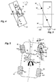
- the Figures 3 and 4 present the right front wheel 40 held by two ball joints 60, defining an inclined pivot axis 62 passing through the centers of these ball joints, allowing a steering wheel ⁇ .
- the pivot axis 62 has a geometry having an inclination in the transverse direction, as well as in the longitudinal direction by forming the flush angle.
- the lever of the lateral offset to the ground d is the transverse distance between the vertical median plane 66 of the wheel 40, and the point of intersection on the ground of the pivot axis 64.
- the lateral lever arm d is negative if the median plane of the road 66 is inside with respect to the point of intersection 64, as shown in the diagrams. In this case a braking of the wheel 40 gives a longitudinal force Fx towards the rear which tends to point the direction of the other side of the vehicle.
- the lever of the longitudinal offset to the ground c representative of the hunt on the ground is the longitudinal distance between the vertical axial plane of the wheel 70, and the ground intersection point of the pivot axis 64.
- longitudinal lever c is positive if the intersection point 64 is in front of the axial plane of the wheel 70. In this case a transverse force Fy towards the inside of the vehicle, tends to steer the direction of this side of the vehicle.
- the action on the steering box 50 of the two transverse forces gives a rotation of the steering wheel if it is free, and an additional steering of the front wheels 40, 42 in one direction or the other.
- the additional steering can go in the direction of the turn obtained by the yaw torque given by the braking of the wheels Mz-brake, or on the contrary to oppose it. meaning.
- the figure 5 present to achieve a moment of lace Mz-brake which tends to rotate the vehicle to the right, the braking of the right front wheel 42 generating a longitudinal force on the wheel Fx2.
- the longitudinal force Fx2 and the transverse forces Fy1, Fy2 applied to the front wheels generate, depending on the lever arms c, d, a torque on the flywheel Cvol which can tend to steer the wheels in the direction of the turn or in the opposite direction .
- the figure 6 present to achieve the same moment of lace Mz-brake which tends to rotate the vehicle to the right, a distribution of braking on the front right wheel 42 corresponding to a coefficient r of the moment of yaw between 0 and 1, and on the right rear wheel 46 corresponding to the coefficient 1-r of this yaw moment.
- the sum of the braking of the two right wheels 40, 42 gives the complete yaw moment Mz-brake.
- the distribution coefficient r can not be too low. In practice with good road grip, the distribution coefficient r is not less than about 0.6.
- the torque on the steering wheel Cvol causes a rotation of the steering wheel in a direction having an amplitude depending on the value of this torque, which can be measured in particular by the steering wheel angle sensor 24.
- the trajectory control method according to the invention will use this feature to perform tests to know the effects of the steering geometry on the torque on the Cvol steering wheel, to anticipate a brake control taking into account as soon as possible. starting this couple in order to obtain faster the right braking pressures on each wheel giving the desired trajectory, with a minimum of corrections.
- the method of controlling the trajectory will also use the torque generated on the Cvol steering wheel to achieve steering of the front wheels in addition to the yaw torque given by the brakes, in order to perform the required turn.
- ADAS Advanced Driver Assistance Systems
- ESP stability control function
- a first strategy first calculates the pressure setpoint to be applied solely to the inner front wheel of the vehicle 42 to obtain the requested yaw torque Mz-brake, then performs this braking.
- the real state of the vehicle can be modified at any time, in particular during front wheel changes, in particular to mount summer or winter tires comprising different rims, for example sheet wheels instead of aluminum wheels with a different geometry.
- test method verifying the state of the vehicle, applies during braking of the vehicle a braking of a front wheel 40, 42, and depending on its effect on the steering deflection, pilot assistance steering 22 to provide a reverse torque opposing this steering to maintain the direction in the state.
- the method then records values of this assistance control dependent on the braking applied.
- the test method applies the maximum possible braking on the front wheel 40, 42, in the limit of adhesion of this wheel, which makes it possible to obtain a significant effect on steering steering.
- the value of the torque C vol delivered by the steering assistance 22 during its driving which is related to the braking level, is then recorded. It is also possible to record values of rotation of the steering wheel 48, given by the steering angle sensor 24. These values are generally available on a multiplexed vehicle information network, of the "CAN" type.
- the test method may be applied periodically to test the state of the vehicle and the geometry of its direction, for example when driving after a kilometer traveled, automatically, or after a request from the system to the driver who must accept it so to be warned.
- the test can be performed after each 2000km period.
- This test can also be carried out by a professional who is familiar with the operation, for example when the vehicle is being overhauled by a dealer.
Description
La présente invention concerne un procédé de contrôle de la trajectoire d'un véhicule automobile avec les freins des roues en l'absence de commande de la direction, ainsi qu'un véhicule automobile équipé de moyens mettant en oeuvre un tel procédé.The present invention relates to a method of controlling the trajectory of a motor vehicle with the wheel brakes in the absence of steering control, and a motor vehicle equipped with means implementing such a method.
Les véhicules automobiles comportent généralement un système de direction comprenant un volant entraînant par une colonne de direction un boîtier situé à sa base, qui transmet de chaque côté du véhicule un mouvement transversal à une biellette équipée de rotules à ses extrémités. En particulier le boîtier peut comporter une crémaillère disposée transversalement.Motor vehicles generally comprise a steering system comprising a steering wheel driving by a steering column a housing located at its base, which transmits on each side of the vehicle a transverse movement to a rod equipped with ball joints at its ends. In particular the housing may comprise a rack arranged transversely.
Le train avant du véhicule comporte de chaque côté un porte-moyeu pouvant pivoter suivant un axe de pivot sensiblement vertical, disposé à proximité du centre de la roue, qui reçoit le mouvement transversal de la biellette pour faire pivoter cette roue autour de l'axe de pivot et assurer la direction.The front axle of the vehicle comprises on each side a hub carrier pivotable about a substantially vertical pivot axis disposed near the center of the wheel, which receives the transverse movement of the link to rotate the wheel about the axis. pivot and provide direction.
Les systèmes de direction peuvent être équipés d'une assistance utilisant une énergie électrique ou hydraulique, qui délivre sur le boîtier de direction une partie du couple nécessaire pour le braquage des roues directrices, complétant celui fourni par le conducteur.The steering systems can be equipped with an assistance using electric or hydraulic energy, which delivers on the steering box a part of the torque necessary for steering wheel steering, supplementing the one provided by the driver.
Par ailleurs les véhicules peuvent être équipés d'un système d'aide à la conduite pour le contrôle de trajectoire appelé « ESP » (Electronic Stability Program), possédant une source autonome de pression hydraulique, qui à partir d'une information sur la trajectoire suivie par le véhicule donnée par différents capteurs, comparée à celle demandée par le conducteur manoeuvrant le volant, agit de manière automatique sur certains freins de roue pour générer un moment de lacet autour de l'axe vertical passant par le sens de gravité du véhicule. On fait ainsi pivoter le véhicule afin de rétablir la trajectoire souhaitée si le système d'aide à la conduite constate une dérive. Le document
Un autre procédé connu de contrôle de trajectoire en cas de défaillance du système de direction, présenté notamment par le document
Ces deux procédés délivrent des forces longitudinales qui génèrent un moment de lacet du véhicule autour de son centre de gravité, assurant une trajectoire du véhicule.These two methods deliver longitudinal forces that generate a moment of yaw of the vehicle around its center of gravity, ensuring a trajectory of the vehicle.
Cependant pour ces procédés, la géométrie particulière de la direction du véhicule peut générer aussi des couples sur le braquage de chaque roue avant entraînant une rotation du volant de direction, ce braquage s'additionnant au moment de lacet venant des forces longitudinales de freinage des roues.However, for these methods, the particular geometry of the direction of the vehicle can also generate torque on the steering of each front wheel causing a rotation of the steering wheel, this steering adding to the moment of yaw from the longitudinal braking forces of the wheels .
Pour une direction autonome du véhicule assurée par le freinage des roues, les couples de braquage pouvant s'appliquer dans un sens ou dans l'autre, posent des problèmes s'ils ne sont pas connus de manière précise, et pris en compte dans les calculs.For autonomous steering of the vehicle provided by the braking of the wheels, the steering torques that can be applied in one direction or the other, pose problems if they are not known precisely, and taken into account in the calculations.
En effet la géométrie de la direction du véhicule peut évoluer, en particulier dans le cas de changements de roues, par exemple en installant des pneumatiques prévus pour une saison avec des jantes comprenant des dimensions différentes.Indeed the geometry of the direction of the vehicle can change, especially in the case of wheel changes, for example by installing tires for a season with rims with different dimensions.
Lors du contrôle de la trajectoire par le freinage, dans le cas d'une réaction du véhicule qui diffère de celle attendue, cet écart nécessite des boucles de correction du calculateur mettant en oeuvre les circuits hydrauliques de freinage présentant une dynamique lente. Le retard mis dans ces corrections peut rendre la trajectoire difficilement contrôlable, et entraîner des accidents.When controlling the trajectory by braking, in the case of a reaction of the vehicle which differs from that expected, this difference requires correction loops of the computer implementing the circuits. hydraulic braking with slow dynamics. The delay in these corrections can make the trajectory difficult to control, and lead to accidents.
La présente invention a notamment pour but d'éviter ces inconvénients de la technique antérieure.The present invention is intended to avoid these disadvantages of the prior art.
Elle propose à cet effet un procédé de test d'une fonction de contrôle de la trajectoire d'un véhicule automobile en l'absence de commande de la direction de ce véhicule, utilisant un système d'aide à la conduite effectuant un contrôle de la trajectoire à partir d'une action individuelle sur les freins de roue, la direction du véhicule comportant une assistance qui peut piloter cette direction, ce procédé étant remarquable en ce qu'au cours du roulage du véhicule il applique un freinage d'une roue avant, et en fonction de son effet sur le braquage de la direction il pilote l'assistance de direction pour délivrer un couple inverse s'opposant à ce braquage afin de maintenir la direction dans l'état, et il enregistre des valeurs de ce pilotage d'assistance dépendant du freinage appliqué.It proposes for this purpose a method of testing a motor vehicle trajectory control function in the absence of control of the steering of the vehicle, using a driver assistance system performing a control of the vehicle. trajectory from an individual action on the wheel brakes, the steering of the vehicle having an assistance that can control this direction, this process being remarkable in that during the rolling of the vehicle it applies a braking of a front wheel , and depending on its effect on the steering deflection it steers the steering assistance to deliver a reverse torque opposing this steering to maintain the direction in the state, and it records values of this steering of the steering. brake-dependent assistance applied.
Un avantage de ce procédé de contrôle est que le test effectué périodiquement permet de connaître de manière simple, efficace et précise l'effet sur la direction d'un freinage d'une roue avant à partir de l'état réel du véhicule, prenant en compte notamment des changements récents sur ce véhicule comme des modifications des roues avant. Le procédé peut ensuite établir directement les pressions optimums de freinage des différentes roues prenant en compte le couple sur le volant donné par la géométrie réelle de la direction.An advantage of this control method is that the test performed periodically makes it possible to know in a simple, effective and precise manner the effect on the steering of a braking of a front wheel from the real state of the vehicle, taking into account This includes recent changes to this vehicle such as front wheel modifications. The method can then directly establish the optimum braking pressures of the different wheels taking into account the torque on the steering wheel given by the actual geometry of the steering.
On obtient alors même après des modifications du véhicule, une rapidité de réaction du contrôle de trajectoire atteignant directement son objectif par la prise en compte d'un couple additionnel du volant de direction, qui assure la sécurité.Even after changes in the vehicle, a response speed of the trajectory control reaches its objective by taking into account an additional torque of the steering wheel, which ensures safety.
Le procédé de contrôle de la trajectoire selon l'invention peut de plus comporter une ou plusieurs des caractéristiques suivantes, qui peuvent être combinées entre elles.The trajectory control method according to the invention may further comprise one or more of the following features, which may be combined with each other.
Avantageusement, le procédé de test applique sensiblement le freinage maximum possible de la roue avant, dans la limite de l'adhérence des roues.Advantageously, the test method applies substantially the maximum possible braking of the front wheel, within the limit of the adhesion of the wheels.
Avantageusement, le procédé de test demande un test de manière périodique. La mise à jour des valeurs de pilotage de l'assistance est ainsi assurée de manière régulière.Advantageously, the test method requires a test periodically. The update of the piloting values of the assistance is thus ensured on a regular basis.
Dans ce cas, en particulier le procédé peut demander un test après des périodes constantes de kilométrage parcouru par le véhicule.In this case, in particular the method may require a test after constant periods of mileage traveled by the vehicle.
Le procédé de test peut informer le conducteur quand il va effectuer un test sur le véhicule.The test method can inform the driver when he will perform a test on the vehicle.
Le procédé de test peut aussi se déclencher après une demande d'un opérateur. On peut en particulier effectuer ce test lors d'une opération de maintenance du véhicule.The test method can also be triggered after a request from an operator. In particular, this test can be carried out during a maintenance operation of the vehicle.
Avantageusement, le procédé de test enregistre la valeur du couple délivré par l'assistance de direction lors de son pilotage.Advantageously, the test method records the value of the torque delivered by the steering assistance during its piloting.
L'invention a aussi pour objet un véhicule automobile équipé de moyens mettant en oeuvre un procédé de test d'une fonction de contrôle de la trajectoire en l'absence de commande de la direction de ce véhicule, ce procédé de test comportant l'une quelconque des caractéristiques précédentes.The invention also relates to a motor vehicle equipped with means implementing a method for testing a control function of the trajectory in the absence of control of the direction of the vehicle, this test method comprising one any of the preceding features.
En particulier, le véhicule automobile peut être équipé d'une assistance de direction qui est électrique.In particular, the motor vehicle can be equipped with a steering assistance which is electric.
En particulier, le véhicule automobile peut comporter un mode de conduite autonome.In particular, the motor vehicle may include an autonomous driving mode.
L'invention sera mieux comprise et d'autres caractéristiques et avantages apparaîtront plus clairement à la lecture de la description ci-après donnée à titre d'exemple, en référence aux dessins annexés dans lesquels :
- la
figure 1 est un schéma synoptique d'un système d'aide à la conduite pour le contrôle de la trajectoire du véhicule avec les freins de roue ; - la
figure 2 présente sur un schéma vu de dessus les efforts sur le véhicule généré par les freinages des roues intérieures, ne prenant pas en compte les effets sur la direction ; - la
figure 3 est un schéma de la roue avant droite vue de l'arrière, présentant le déport au sol du pivot de roue par rapport à l'axe vertical de cette roue ; - la
figure 4 est un schéma de la roue avant droite vu de dessus, présentant les bras de levier de la géométrie de la direction ; - la
figure 5 présente les efforts sur le véhicule générés par un freinage d'une roue avant intérieure, comprenant les effets sur la direction ; et - la
figure 6 présente les efforts sur le véhicule générés par un freinage des roues avant et arrière intérieures, comprenant les effets sur la direction.
- the
figure 1 is a block diagram of a driver assistance system for controlling the vehicle trajectory with wheel brakes; - the
figure 2 shows in a diagram seen from above the forces on the vehicle generated by the braking of the inner wheels, not taking into account the effects on the steering; - the
figure 3 is a diagram of the right front wheel seen from the rear, showing the ground offset of the wheel pivot relative to the vertical axis of this wheel; - the
figure 4 is a diagram of the front right wheel seen from above, presenting the lever arms of the geometry of the direction; - the
figure 5 presents the forces on the vehicle generated by braking an inner front wheel, including effects on steering; and - the
figure 6 presents the forces on the vehicle generated by braking the front and rear inner wheels, including effects on steering.
La
Suivant les besoins du véhicule, notamment pour éviter un blocage des roues ou une déviation de trajectoire, la fonction d'arbitrage 8 envoie des consignes de freinage individuel de chaque roue à une fonction bas niveau 10, qui délivre à partir d'une pompe hydraulique une pression individuelle 12 sur chaque frein de roue 14.Depending on the needs of the vehicle, in particular to prevent a wheel lock or a trajectory deviation, the arbitration function 8 sends individual braking instructions of each wheel to a
Un volant de direction 20 équipé d'une assistance 22 qui peut être électrique ou hydraulique, comporte un capteur d'angle volant 24.A
Lors d'une défaillance de la commande de direction 20 venant par exemple d'une panne de son assistance 22, comme un défaut d'un capteur ou de la fourniture d'énergie, une fonction de mode de défaillance 26 du système de contrôle de trajectoire 2 échange des informations 32 avec le système de direction pour appliquer un contrôle de trajectoire.In the event of a failure of the
En variante le contrôle de trajectoire peut être aussi appliqué sur un véhicule à conduite autonome en cas de défaillance de la commande de direction.Alternatively the trajectory control can also be applied to a self-driving vehicle in case of failure of the steering control.
Dans ce cas la fonction mode de défaillance 26 calcule alors un moment de lacet à établir pour assurer la trajectoire du véhicule, qu'il délivre à la fonction d'arbitrage 8 appliquant par la fonction bas niveau 10 les pressions individuelles 12 sur les freins de roue 14.In this case, the failure mode function 26 then calculates a yaw moment to be established to ensure the trajectory of the vehicle, which it delivers. the arbitration function 8 applying by the
La
En l'absence de couple sur le volant 48 qui est lâché, on applique un freinage donnant une force longitudinale Fx2 sur la roue avant droite 42, Fx3 sur la roue arrière gauche 44 et Fx4 sur la roue arrière droite 46. Ces différentes forces longitudinales génèrent un moment de lacet Mz-frein sur le véhicule.In the absence of torque on the
Le moment de lacet Mz-frein applique une force transversale sur chaque roue Fy1, Fy2, Fy3, Fy4.The yaw moment Mz-brake applies a transverse force on each wheel Fy1, Fy2, Fy3, Fy4.
Il résulte de la somme des différentes forces longitudinales Fx et transversales Fy sur les quatre roues du véhicule, une accélération angulaire de ce véhicule autour de son centre de gravité O. En multipliant le moment d'inertie du véhicule autour du centre de gravité O par l'accélération angulaire, et en ajoutant la vitesse angulaire donnée par le braquage des roues avant directrices 40, 42, on obtient la vitesse de lacet du véhicule Ψ' qui le fait pivoter.It results from the sum of the different longitudinal forces Fx and transverse Fy on the four wheels of the vehicle, an angular acceleration of this vehicle around its center of gravity O. By multiplying the moment of inertia of the vehicle around the center of gravity O by the angular acceleration, and adding the angular velocity given by the steering of the
En particulier le freinage des roues droite 42, 46 donne un moment de lacet Mz-frein qui fait pivoter le véhicule vers la droite, et le freinage des roues gauche 40, 44 donne un moment de lacet dans l'autre sens.In particular the braking of the
Les
Le bras de levier du déport latéral au sol d est la distance transversale entre le plan médian vertical 66 de la roue 40, et le point d'intersection au sol de l'axe de pivot 64. Le bras de levier latéral d est négatif si le plan médian de la route 66 est à l'intérieur par rapport au point d'intersection 64, comme présenté sur les schémas. Dans ce cas un freinage de la roue 40 donne une force longitudinale Fx vers l'arrière qui tend à braquer la direction de l'autre côté du véhicule.The lever of the lateral offset to the ground d is the transverse distance between the vertical
Le bras de levier du déport longitudinal au sol c représentatif de la chasse au sol, est la distance longitudinale entre le plan axial vertical de la roue 70, et le point d'intersection au sol de l'axe de pivot 64. Ce bras de levier longitudinal c est positif si le point d'intersection 64 est devant le plan axial de la roue 70. Dans ce cas une force transversale Fy vers l'intérieur du véhicule, tend à braquer la direction de ce côté du véhicule.The lever of the longitudinal offset to the ground c representative of the hunt on the ground, is the longitudinal distance between the vertical axial plane of the
Chaque bras de levier c, d multiplié par la force longitudinale Fx ou transversale Fy appliquée par la route sur la roue, génère un couple de rotation de cette roue autour de son axe de pivot 62 dans un sens ou dans l'autre.Each lever arm c, d multiplied by the longitudinal force Fx or transverse force Fy applied by the road to the wheel, generates a rotational torque of this wheel about its
On a alors lors des freinages individuels des roues mis en oeuvre par le système de contrôle de trajectoire 2, pour une roue avant 40, 42 un couple de rotation autour de l'axe de pivot 62 dépendant de la géométrie de la direction, des deux forces Fx, Fy appliquées sur cette roue et de l'angle de braquage de la roue δ. Ces couples de rotation génèrent une force transversale globale sur la crémaillère du boîtier de direction 50.Then, during the individual braking of the wheels used by the
En retirant de la force transversale sur la crémaillère du boîtier de direction 50, les forces de frottement dans ce boîtier, et en prenant en compte le rayon du pignon de la crémaillère, on obtient un couple généré sur le volant Cvol.By removing the transverse force on the rack of the
L'action sur le boîtier de direction 50 des deux forces transversales donne une rotation du volant s'il est libre, et un braquage additionnel des roues avant 40, 42 dans un sens ou dans l'autre.The action on the
Lors d'un contrôle de trajectoire du véhicule par le freinage individuel des roues, le braquage additionnel peut aller dans le sens du virage obtenu par le couple de lacet donné par le freinage des roues Mz-frein, ou au contraire s'opposer à ce sens.During a control of the vehicle trajectory by the individual braking of the wheels, the additional steering can go in the direction of the turn obtained by the yaw torque given by the braking of the wheels Mz-brake, or on the contrary to oppose it. meaning.
Il est donc intéressant de connaître à l'avance la valeur de la rotation additionnelle du volant 48 résultant d'un certain freinage des différentes roues, pour ajuster ces freinages en fonction de cette rotation prévue, afin d'obtenir de manière rapide les meilleures valeurs. On notera que les différents frottements dans la direction s'opposant au mouvement, réduisent les effets des forces transversales appliquées sur le boîtier de direction 50, et la valeur du couple résultant sur le volant Cvol.It is therefore interesting to know in advance the value of the additional rotation of the
On améliore ainsi la réactivité du système de contrôle de trajectoire, comprenant une dynamique assez lente à cause notamment du temps de réponse des circuits hydrauliques, en évitant des boucles d'itérations de son fonctionnement qui demandent du temps, et peuvent apporter un risque de perte de contrôle complet de la trajectoire.This improves the responsiveness of the trajectory control system, including a fairly slow dynamic due in particular the response time of the hydraulic circuits, avoiding iteration loops of its operation that require time, and can bring a risk of loss complete control of the trajectory.
La
La force longitudinale Fx2 et les forces transversales Fy1, Fy2 appliquées sur les roues avant génèrent en fonction des bras de levier c, d, un couple sur le volant Cvol qui peut tendre à braquer les roues dans le sens du virage ou dans le sens opposé.The longitudinal force Fx2 and the transverse forces Fy1, Fy2 applied to the front wheels generate, depending on the lever arms c, d, a torque on the flywheel Cvol which can tend to steer the wheels in the direction of the turn or in the opposite direction .
En pratique on peut constater sur des véhicules de gamme supérieure une plage du déport transversal au sol d allant d'une valeur faiblement positive, environ 2mm, à une valeur fortement négative, environ -23mm, et une plage de la chasse au sol c comprise entre deux valeurs fortement positives, environ 24 et 27mm. On obtient avec ces véhicules un couple sur le volant Cvol dans une plage comprenant des valeurs positives et négatives.In practice we can see on vehicles of higher range a range of the transverse displacement to the ground d ranging from a weakly positive value, about 2mm, to a strongly negative value, about -23mm, and a range of hunting ground included c between two strongly positive values, about 24 and 27mm. With these vehicles, we obtain a torque on the steering wheel Cvol in a range including positive and negative values.
La
Le freinage sur la roue arrière est limité en fonction de l'adhérence au sol afin d'éviter un dérapage de cette roue, le coefficient de répartition r ne peut pas être trop faible. En pratique avec une bonne adhérence de la route, le coefficient de répartition r n'est pas inférieur à environ 0,6.The braking on the rear wheel is limited according to the grip on the ground to avoid a skid of this wheel, the distribution coefficient r can not be too low. In practice with good road grip, the distribution coefficient r is not less than about 0.6.
Le freinage sur la roue avant droite 42 étant réduit, on obtient une force transversale appliquée sur la crémaillère de direction 50 qui est diminuée, et un couple sur le volant Cvol diminué aussi.The braking on the
Le couple sur le volant Cvol entraîne une rotation du volant dans un sens présentant une amplitude dépendant de la valeur de ce couple, qui peut être mesurée notamment par le capteur d'angle volant 24.The torque on the steering wheel Cvol causes a rotation of the steering wheel in a direction having an amplitude depending on the value of this torque, which can be measured in particular by the steering
Le procédé de contrôle de trajectoire suivant l'invention va utiliser cette particularité pour effectuer des tests permettant de connaître les effets de la géométrie de la direction sur le couple sur le volant Cvol, permettant d'anticiper un contrôle des freins en prenant en compte dès le départ ce couple afin d'obtenir plus rapidement les bonnes pressions de freinage sur chaque roue donnant la trajectoire souhaitée, avec un minimum de corrections.The trajectory control method according to the invention will use this feature to perform tests to know the effects of the steering geometry on the torque on the Cvol steering wheel, to anticipate a brake control taking into account as soon as possible. starting this couple in order to obtain faster the right braking pressures on each wheel giving the desired trajectory, with a minimum of corrections.
Le procédé de contrôle de la trajectoire va aussi utiliser le couple généré sur le volant Cvol pour réaliser un braquage des roues avant s'ajoutant au couple de lacet donné par les freins, afin d'effectuer le virage demandé.The method of controlling the trajectory will also use the torque generated on the Cvol steering wheel to achieve steering of the front wheels in addition to the yaw torque given by the brakes, in order to perform the required turn.
Différentes stratégies sont utilisables avec le procédé de contrôle selon l'invention, notamment pour des véhicules équipés de systèmes d'aide à la conduite, appelés aussi « ADAS » (Advanced Driver Assistance Systems), ou de systèmes de conduite autonome, dans le cas de défaillance d'un organe qui entraîne la nécessité d'assurer une trajectoire avec les freins du véhicule, en utilisant notamment une fonction de contrôle de stabilité du type « ESP ».Different strategies can be used with the control method according to the invention, especially for vehicles equipped with driver assistance systems, also called "ADAS" (Advanced Driver Assistance Systems), or autonomous driving systems, in the case failure of a member that causes the need to ensure a path with the brakes of the vehicle, including using a stability control function of the type "ESP".
Ces stratégies permettent de prendre en compte les effets directs et réels sur la direction pour un véhicule dans l'état dans lequel il se trouve, quelles que soient les modifications apportées dans le passé à ce véhicule, pour obtenir au plus vite les bons ajustements des freinages donnant la trajectoire demandée.These strategies make it possible to take into account the direct and real effects on the direction of a vehicle in the state in which it is located, whatever the modifications made in the past to this vehicle, to obtain as quickly as possible the good adjustments of the braking giving the requested trajectory.
On a pour toutes ces stratégies en premier un calcul du moment de lacet Mz-frein correspondant au virage à effectuer.We have for all these strategies first a calculation of the moment of yaw Mz-brake corresponding to the turn to be made.
Une première stratégie calcule d'abord la consigne de pression à appliquer uniquement sur la roue avant intérieure du véhicule 42 pour obtenir le couple de lacet demandé Mz-frein, puis effectue ce freinage.A first strategy first calculates the pressure setpoint to be applied solely to the inner front wheel of the
Si au cours du freinage la rotation du volant de direction est dans le sens du virage à effectuer, cette action est positive pour aider le véhicule a tourner, et on maintient alors la totalité de ce freinage de la roue avant intérieure 42. On réalise alors seulement un ajustement du couple de lacet demandé par les freins Mz-frein pour tenir compte de l'effet positif de la rotation du volant.If during braking the rotation of the steering wheel is in the direction of the turn to be made, this action is positive to help the vehicle to turn, and then maintains all of the braking of the
Si la rotation du volant de direction est dans le sens opposé au virage à effectuer, cette action est négative. On décide alors de baisser la pression sur la roue avant intérieure 42 de manière à réduire cet effet négatif, pour en transférer une partie sur la roue arrière intérieure 46 ce qui modifie l'effet sur la rotation du volant. La somme des freinages des deux roues intérieures 42, 46 est calculée pour obtenir le même couple de lacet demandé Mz-frein, en tenant compte d'une éventuelle rotation du volant.If the rotation of the steering wheel is in the opposite direction to the turn to be made, this action is negative. It is then decided to lower the pressure on the
L'état réel du véhicule peut être modifié à tout moment, en particulier lors de changements de roues avant, notamment pour monter des pneumatiques été ou hiver comprenant des jantes différentes, par exemple des jantes en tôle à la place de jantes en aluminium avec une géométrie différente.The real state of the vehicle can be modified at any time, in particular during front wheel changes, in particular to mount summer or winter tires comprising different rims, for example sheet wheels instead of aluminum wheels with a different geometry.
Le procédé de test selon l'invention vérifiant l'état du véhicule, applique au cours du roulage du véhicule un freinage d'une roue avant 40, 42, et en fonction de son effet sur le braquage de la direction, pilote l'assistance de direction 22 pour délivrer un couple inverse s'opposant à ce braquage afin de maintenir la direction dans l'état. Le procédé enregistre ensuite des valeurs de ce pilotage d'assistance dépendant du freinage appliqué.The test method according to the invention verifying the state of the vehicle, applies during braking of the vehicle a braking of a
Avantageusement le procédé de test applique le freinage maximum possible sur la roue avant 40, 42, dans la limite d'adhérence de cette roue, ce qui permet d'obtenir un effet important sur le braquage de la direction.Advantageously, the test method applies the maximum possible braking on the
En particulier on enregistre alors la valeur du couple Cvol délivré par l'assistance de direction 22 lors de son pilotage, qui est mise en relation avec le niveau de freinage. On peut aussi enregistrer des valeurs de rotation du volant 48, données par le capteur d'angle volant 24. Ces valeurs sont généralement disponibles sur un réseau multiplexé d'informations du véhicule, du type « CAN ».In particular, the value of the torque C vol delivered by the
Le procédé de test peut être appliqué périodiquement pour tester l'état du véhicule et la géométrie de sa direction, par exemple lors du roulage après un kilométrage parcouru, de manière automatique, ou après une demande du système au conducteur qui doit l'accepter afin d'être prévenu. On peut effectuer par exemple le test après chaque période de 2000km. Ce test peut aussi être effectué par un professionnel maîtrisant l'opération, par exemple lors du passage du véhicule en révision chez un concessionnaire.The test method may be applied periodically to test the state of the vehicle and the geometry of its direction, for example when driving after a kilometer traveled, automatically, or after a request from the system to the driver who must accept it so to be warned. For example, the test can be performed after each 2000km period. This test can also be carried out by a professional who is familiar with the operation, for example when the vehicle is being overhauled by a dealer.
On enregistre alors les résultats obtenus par le test afin de les garder en mémoire, et de les utiliser dès la mise en oeuvre d'un contrôle de la trajectoire suivant, afin d'obtenir aussitôt les meilleures valeurs de contrôle des freins.The results obtained by the test are then recorded in order to keep them in memory, and to use them as soon as the following trajectory control is implemented, in order to obtain the best brake control values immediately.
On notera que ce procédé de test d'une fonction de contrôle de la trajectoire nécessite seulement des compléments de logiciels dans un calculateur d'un système d'aide à la conduite, ce qui représente un coût réduit.It should be noted that this method of testing a trajectory control function requires only software complements in a computer of a driver assistance system, which represents a reduced cost.
Claims (10)
- Method for testing a control function of a motor vehicle trajectory in the absence of a steering control of this vehicle, using a driving assistance system (2) that controls the trajectory from an individual action on the wheel brakes (14), with the steering of the vehicle comprising a power steering (22) system, which can control this steering, characterised by the fact that while the vehicle is in motion it applies a braking of a front wheel (40, 42), and according to the effect thereof on the steering angle it controls the power steering (22) in order to deliver a reverse torque that opposes this counter-steering in order to maintain the direction as is, and it records the values of this assisted driving depending on the braking applied.
- Test method according to claim 1, characterised by the fact that it substantially applies the maximum braking possible of the front wheel (40, 42), within the adhesion limit of the wheels.
- Test method according to claim 1 or 2, characterised by the fact that it requests a test periodically.
- Test method according to claim 3, characterised by the fact that it requests a test after constant mileages travelled by the vehicle.
- Test method according to claim 3 or 4, characterised by the fact that it informs the driver when a test will be conducted on the vehicle.
- Test method according to any of the preceding claims, characterised by the fact that it is triggered after a request from an operator.
- Test method according to any of the preceding claims, characterised by the fact that it records the torque value (Cvol) delivered by the power steering (22) during the control thereof.
- Motor vehicle provided with means implementing a method for testing a trajectory control function in the absence of a steering control of this vehicle, characterised by the fact that the test method is according to any of the preceding claims.
- Motor vehicle according to claim 8, characterised by the fact that it is provided with an electric power steering (22).
- Motor vehicle according to claim 8 or 9, characterised by the fact that it comprises a self-driving mode.
Applications Claiming Priority (1)
| Application Number | Priority Date | Filing Date | Title |
|---|---|---|---|
| FR1559331A FR3041919B1 (en) | 2015-10-01 | 2015-10-01 | TESTING A CONTROL FUNCTION OF THE TRACK OF A VEHICLE WITH BRAKES WITHOUT STEERING CONTROL |
Publications (2)
| Publication Number | Publication Date |
|---|---|
| EP3150452A1 EP3150452A1 (en) | 2017-04-05 |
| EP3150452B1 true EP3150452B1 (en) | 2018-08-22 |
Family
ID=54608850
Family Applications (1)
| Application Number | Title | Priority Date | Filing Date |
|---|---|---|---|
| EP16186848.4A Active EP3150452B1 (en) | 2015-10-01 | 2016-09-01 | Test of a function for controlling the trajectory of a vehicle using the brakes without controlling the steering wheel |
Country Status (3)
| Country | Link |
|---|---|
| EP (1) | EP3150452B1 (en) |
| ES (1) | ES2685704T3 (en) |
| FR (1) | FR3041919B1 (en) |
Families Citing this family (1)
| Publication number | Priority date | Publication date | Assignee | Title |
|---|---|---|---|---|
| CN109557836B (en) * | 2017-09-26 | 2021-05-14 | 比亚迪股份有限公司 | Controller circuit board, controller and vehicle of rear wheel follow-up steering system |
Family Cites Families (5)
| Publication number | Priority date | Publication date | Assignee | Title |
|---|---|---|---|---|
| DE10242123A1 (en) * | 2002-09-11 | 2004-03-25 | Robert Bosch Gmbh | Motor vehicle dynamic stability system operation method in which mathematical models are used to check the measurement signals of the stability system sensors in two groups with two models |
| JP3972913B2 (en) | 2004-03-26 | 2007-09-05 | トヨタ自動車株式会社 | Vehicle travel control device |
| US7630807B2 (en) * | 2004-07-15 | 2009-12-08 | Hitachi, Ltd. | Vehicle control system |
| FR2914260A1 (en) * | 2007-03-27 | 2008-10-03 | Renault Sas | Four wheeled motor vehicle e.g. industrial vehicle, for e.g. building site, has electronic control unit including auxiliary units decelerating torques to be applied on wheels found at interior or exterior of turning via units, respectively |
| WO2012073358A1 (en) * | 2010-12-01 | 2012-06-07 | トヨタ自動車株式会社 | Vehicle motion control apparatus |
-
2015
- 2015-10-01 FR FR1559331A patent/FR3041919B1/en active Active
-
2016
- 2016-09-01 EP EP16186848.4A patent/EP3150452B1/en active Active
- 2016-09-01 ES ES16186848.4T patent/ES2685704T3/en active Active
Non-Patent Citations (1)
| Title |
|---|
| None * |
Also Published As
| Publication number | Publication date |
|---|---|
| FR3041919A1 (en) | 2017-04-07 |
| ES2685704T3 (en) | 2018-10-10 |
| EP3150452A1 (en) | 2017-04-05 |
| FR3041919B1 (en) | 2017-12-08 |
Similar Documents
| Publication | Publication Date | Title |
|---|---|---|
| EP3938260B1 (en) | Method for generating a setpoint for the combined control of a wheel-steering system and of a differential braking system of a motor vehicle | |
| EP2373529B1 (en) | Method for determining the understeering ratio of a vehicle provided with electric power steering and for optionally correcting the power steering | |
| EP0598155B1 (en) | Turn controlling method and device for vehicle with non-steered wheels or tracks | |
| FR2949414A1 (en) | SYSTEM FOR STABILIZING THE CIRCULATION DIRECTION OF A VEHICLE | |
| EP3344518B1 (en) | Road vehicle convoy control method, and road vehicle convoy | |
| EP3150452B1 (en) | Test of a function for controlling the trajectory of a vehicle using the brakes without controlling the steering wheel | |
| EP1209053B1 (en) | Active drive assist method for motor vehicle in case of a split-mu braking | |
| EP3150451B1 (en) | Method for controlling the trajectory of a vehicle using the brakes, without controlling the steering wheel | |
| EP1907260B1 (en) | Method for controlling the steering orientation of a vehicle | |
| FR2850346A1 (en) | ASSISTED STEERING METHOD AND ASSISTED STEERING OF VEHICLES | |
| EP1592599B1 (en) | Method of reducing the turning speed of a vehicle | |
| FR2954256A1 (en) | METHOD FOR IDENTIFYING A DIRECTOR WHEEL ADHERENCE LOSS PHASE OF A VEHICLE | |
| EP2528788B1 (en) | System and method for tracking the path of a vehicle | |
| FR2896754A1 (en) | METHOD FOR REDUCING THE BRAKING DISTANCE OF A MOTOR VEHICLE AND DEVICE FOR IMPLEMENTING SAID METHOD | |
| FR2942440A1 (en) | Motor vehicle e.g. car, dynamic behavior controlling method, involves distributing set point deceleration on left and right wheels of vehicle based on value of longitudinal distribution parameter and of parameter value of side distribution | |
| FR2916717A3 (en) | Yawing moment application controlling device for motor vehicle, has front axle with wheels, where device emits setpoint towards piloting unit and control system respectively for applying brake and motor torques on wheels | |
| WO2010010263A1 (en) | Method for controlling the understeering of an automobile | |
| FR2968628A1 (en) | Method for controlling traffic lane monitoring assistance function using steering system of motor vehicle, involves calculating assistance torque, and adding base angle regulation torque and assistance torque to obtain set point torque | |
| FR2989659A1 (en) | Control device for improving drivability of motor vehicle moving on e.g. snowy road with low adherence, has controller providing control set point for controlling swiveling of weak angle of drive wheel moving on road with low adherence | |
| FR3092914A1 (en) | Method for determining the trajectory of a vehicle comprising four steered wheels | |
| FR3123615A1 (en) | Torque vectoring system, method and associated vehicle | |
| FR2896753A1 (en) | Torque variation compensating method for vehicle, involves developing compensation torque set point according to displacement data and camber set point, and sending torque set point to actuator that exerts torque on steering wheel | |
| FR2924381A3 (en) | Anti-rolling device controlling system for motor vehicle, has electronic control unit for activating and deactivating anti-rolling device based on vehicle operating parameters comprising rolling angles and longitudinal speed of vehicle | |
| EP1982888A1 (en) | Method for closed-loop stability control for an automobile | |
| EP1982887A1 (en) | Method for open-loop stability control for an automobile |
Legal Events
| Date | Code | Title | Description |
|---|---|---|---|
| PUAI | Public reference made under article 153(3) epc to a published international application that has entered the european phase |
Free format text: ORIGINAL CODE: 0009012 |
|
| AK | Designated contracting states |
Kind code of ref document: A1 Designated state(s): AL AT BE BG CH CY CZ DE DK EE ES FI FR GB GR HR HU IE IS IT LI LT LU LV MC MK MT NL NO PL PT RO RS SE SI SK SM TR |
|
| AX | Request for extension of the european patent |
Extension state: BA ME |
|
| RAP1 | Party data changed (applicant data changed or rights of an application transferred) |
Owner name: PSA AUTOMOBILES SA |
|
| 17P | Request for examination filed |
Effective date: 20171002 |
|
| RBV | Designated contracting states (corrected) |
Designated state(s): AL AT BE BG CH CY CZ DE DK EE ES FI FR GB GR HR HU IE IS IT LI LT LU LV MC MK MT NL NO PL PT RO RS SE SI SK SM TR |
|
| GRAP | Despatch of communication of intention to grant a patent |
Free format text: ORIGINAL CODE: EPIDOSNIGR1 |
|
| RIC1 | Information provided on ipc code assigned before grant |
Ipc: B60W 10/20 20060101ALI20180214BHEP Ipc: B60W 50/02 20120101ALI20180214BHEP Ipc: B60W 10/18 20120101AFI20180214BHEP |
|
| INTG | Intention to grant announced |
Effective date: 20180309 |
|
| GRAS | Grant fee paid |
Free format text: ORIGINAL CODE: EPIDOSNIGR3 |
|
| GRAA | (expected) grant |
Free format text: ORIGINAL CODE: 0009210 |
|
| AK | Designated contracting states |
Kind code of ref document: B1 Designated state(s): AL AT BE BG CH CY CZ DE DK EE ES FI FR GB GR HR HU IE IS IT LI LT LU LV MC MK MT NL NO PL PT RO RS SE SI SK SM TR |
|
| REG | Reference to a national code |
Ref country code: GB Ref legal event code: FG4D Free format text: NOT ENGLISH |
|
| REG | Reference to a national code |
Ref country code: CH Ref legal event code: EP |
|
| REG | Reference to a national code |
Ref country code: AT Ref legal event code: REF Ref document number: 1032103 Country of ref document: AT Kind code of ref document: T Effective date: 20180915 |
|
| REG | Reference to a national code |
Ref country code: IE Ref legal event code: FG4D Free format text: LANGUAGE OF EP DOCUMENT: FRENCH Ref country code: FR Ref legal event code: PLFP Year of fee payment: 3 |
|
| REG | Reference to a national code |
Ref country code: DE Ref legal event code: R096 Ref document number: 602016004942 Country of ref document: DE |
|
| REG | Reference to a national code |
Ref country code: ES Ref legal event code: FG2A Ref document number: 2685704 Country of ref document: ES Kind code of ref document: T3 Effective date: 20181010 |
|
| REG | Reference to a national code |
Ref country code: DE Ref legal event code: R084 Ref document number: 602016004942 Country of ref document: DE |
|
| REG | Reference to a national code |
Ref country code: GB Ref legal event code: 746 Effective date: 20181029 |
|
| REG | Reference to a national code |
Ref country code: NL Ref legal event code: MP Effective date: 20180822 |
|
| REG | Reference to a national code |
Ref country code: LT Ref legal event code: MG4D |
|
| PG25 | Lapsed in a contracting state [announced via postgrant information from national office to epo] |
Ref country code: FI Free format text: LAPSE BECAUSE OF FAILURE TO SUBMIT A TRANSLATION OF THE DESCRIPTION OR TO PAY THE FEE WITHIN THE PRESCRIBED TIME-LIMIT Effective date: 20180822 Ref country code: LT Free format text: LAPSE BECAUSE OF FAILURE TO SUBMIT A TRANSLATION OF THE DESCRIPTION OR TO PAY THE FEE WITHIN THE PRESCRIBED TIME-LIMIT Effective date: 20180822 Ref country code: IS Free format text: LAPSE BECAUSE OF FAILURE TO SUBMIT A TRANSLATION OF THE DESCRIPTION OR TO PAY THE FEE WITHIN THE PRESCRIBED TIME-LIMIT Effective date: 20181222 Ref country code: NL Free format text: LAPSE BECAUSE OF FAILURE TO SUBMIT A TRANSLATION OF THE DESCRIPTION OR TO PAY THE FEE WITHIN THE PRESCRIBED TIME-LIMIT Effective date: 20180822 Ref country code: BG Free format text: LAPSE BECAUSE OF FAILURE TO SUBMIT A TRANSLATION OF THE DESCRIPTION OR TO PAY THE FEE WITHIN THE PRESCRIBED TIME-LIMIT Effective date: 20181122 Ref country code: GR Free format text: LAPSE BECAUSE OF FAILURE TO SUBMIT A TRANSLATION OF THE DESCRIPTION OR TO PAY THE FEE WITHIN THE PRESCRIBED TIME-LIMIT Effective date: 20181123 Ref country code: NO Free format text: LAPSE BECAUSE OF FAILURE TO SUBMIT A TRANSLATION OF THE DESCRIPTION OR TO PAY THE FEE WITHIN THE PRESCRIBED TIME-LIMIT Effective date: 20181122 Ref country code: RS Free format text: LAPSE BECAUSE OF FAILURE TO SUBMIT A TRANSLATION OF THE DESCRIPTION OR TO PAY THE FEE WITHIN THE PRESCRIBED TIME-LIMIT Effective date: 20180822 Ref country code: SE Free format text: LAPSE BECAUSE OF FAILURE TO SUBMIT A TRANSLATION OF THE DESCRIPTION OR TO PAY THE FEE WITHIN THE PRESCRIBED TIME-LIMIT Effective date: 20180822 |
|
| REG | Reference to a national code |
Ref country code: AT Ref legal event code: MK05 Ref document number: 1032103 Country of ref document: AT Kind code of ref document: T Effective date: 20180822 |
|
| PG25 | Lapsed in a contracting state [announced via postgrant information from national office to epo] |
Ref country code: LV Free format text: LAPSE BECAUSE OF FAILURE TO SUBMIT A TRANSLATION OF THE DESCRIPTION OR TO PAY THE FEE WITHIN THE PRESCRIBED TIME-LIMIT Effective date: 20180822 Ref country code: AL Free format text: LAPSE BECAUSE OF FAILURE TO SUBMIT A TRANSLATION OF THE DESCRIPTION OR TO PAY THE FEE WITHIN THE PRESCRIBED TIME-LIMIT Effective date: 20180822 Ref country code: HR Free format text: LAPSE BECAUSE OF FAILURE TO SUBMIT A TRANSLATION OF THE DESCRIPTION OR TO PAY THE FEE WITHIN THE PRESCRIBED TIME-LIMIT Effective date: 20180822 |
|
| PG25 | Lapsed in a contracting state [announced via postgrant information from national office to epo] |
Ref country code: PL Free format text: LAPSE BECAUSE OF FAILURE TO SUBMIT A TRANSLATION OF THE DESCRIPTION OR TO PAY THE FEE WITHIN THE PRESCRIBED TIME-LIMIT Effective date: 20180822 Ref country code: EE Free format text: LAPSE BECAUSE OF FAILURE TO SUBMIT A TRANSLATION OF THE DESCRIPTION OR TO PAY THE FEE WITHIN THE PRESCRIBED TIME-LIMIT Effective date: 20180822 Ref country code: IT Free format text: LAPSE BECAUSE OF FAILURE TO SUBMIT A TRANSLATION OF THE DESCRIPTION OR TO PAY THE FEE WITHIN THE PRESCRIBED TIME-LIMIT Effective date: 20180822 Ref country code: AT Free format text: LAPSE BECAUSE OF FAILURE TO SUBMIT A TRANSLATION OF THE DESCRIPTION OR TO PAY THE FEE WITHIN THE PRESCRIBED TIME-LIMIT Effective date: 20180822 Ref country code: RO Free format text: LAPSE BECAUSE OF FAILURE TO SUBMIT A TRANSLATION OF THE DESCRIPTION OR TO PAY THE FEE WITHIN THE PRESCRIBED TIME-LIMIT Effective date: 20180822 Ref country code: CZ Free format text: LAPSE BECAUSE OF FAILURE TO SUBMIT A TRANSLATION OF THE DESCRIPTION OR TO PAY THE FEE WITHIN THE PRESCRIBED TIME-LIMIT Effective date: 20180822 |
|
| REG | Reference to a national code |
Ref country code: DE Ref legal event code: R097 Ref document number: 602016004942 Country of ref document: DE |
|
| PG25 | Lapsed in a contracting state [announced via postgrant information from national office to epo] |
Ref country code: DK Free format text: LAPSE BECAUSE OF FAILURE TO SUBMIT A TRANSLATION OF THE DESCRIPTION OR TO PAY THE FEE WITHIN THE PRESCRIBED TIME-LIMIT Effective date: 20180822 Ref country code: SM Free format text: LAPSE BECAUSE OF FAILURE TO SUBMIT A TRANSLATION OF THE DESCRIPTION OR TO PAY THE FEE WITHIN THE PRESCRIBED TIME-LIMIT Effective date: 20180822 Ref country code: SK Free format text: LAPSE BECAUSE OF FAILURE TO SUBMIT A TRANSLATION OF THE DESCRIPTION OR TO PAY THE FEE WITHIN THE PRESCRIBED TIME-LIMIT Effective date: 20180822 |
|
| REG | Reference to a national code |
Ref country code: BE Ref legal event code: MM Effective date: 20180930 |
|
| REG | Reference to a national code |
Ref country code: IE Ref legal event code: MM4A |
|
| PG25 | Lapsed in a contracting state [announced via postgrant information from national office to epo] |
Ref country code: LU Free format text: LAPSE BECAUSE OF NON-PAYMENT OF DUE FEES Effective date: 20180901 Ref country code: MC Free format text: LAPSE BECAUSE OF FAILURE TO SUBMIT A TRANSLATION OF THE DESCRIPTION OR TO PAY THE FEE WITHIN THE PRESCRIBED TIME-LIMIT Effective date: 20180822 |
|
| PLBE | No opposition filed within time limit |
Free format text: ORIGINAL CODE: 0009261 |
|
| STAA | Information on the status of an ep patent application or granted ep patent |
Free format text: STATUS: NO OPPOSITION FILED WITHIN TIME LIMIT |
|
| 26N | No opposition filed |
Effective date: 20190523 |
|
| PG25 | Lapsed in a contracting state [announced via postgrant information from national office to epo] |
Ref country code: IE Free format text: LAPSE BECAUSE OF NON-PAYMENT OF DUE FEES Effective date: 20180901 |
|
| PG25 | Lapsed in a contracting state [announced via postgrant information from national office to epo] |
Ref country code: BE Free format text: LAPSE BECAUSE OF NON-PAYMENT OF DUE FEES Effective date: 20180930 Ref country code: SI Free format text: LAPSE BECAUSE OF FAILURE TO SUBMIT A TRANSLATION OF THE DESCRIPTION OR TO PAY THE FEE WITHIN THE PRESCRIBED TIME-LIMIT Effective date: 20180822 |
|
| PG25 | Lapsed in a contracting state [announced via postgrant information from national office to epo] |
Ref country code: MT Free format text: LAPSE BECAUSE OF FAILURE TO SUBMIT A TRANSLATION OF THE DESCRIPTION OR TO PAY THE FEE WITHIN THE PRESCRIBED TIME-LIMIT Effective date: 20180822 |
|
| PG25 | Lapsed in a contracting state [announced via postgrant information from national office to epo] |
Ref country code: TR Free format text: LAPSE BECAUSE OF FAILURE TO SUBMIT A TRANSLATION OF THE DESCRIPTION OR TO PAY THE FEE WITHIN THE PRESCRIBED TIME-LIMIT Effective date: 20180822 |
|
| PG25 | Lapsed in a contracting state [announced via postgrant information from national office to epo] |
Ref country code: PT Free format text: LAPSE BECAUSE OF FAILURE TO SUBMIT A TRANSLATION OF THE DESCRIPTION OR TO PAY THE FEE WITHIN THE PRESCRIBED TIME-LIMIT Effective date: 20180822 |
|
| REG | Reference to a national code |
Ref country code: CH Ref legal event code: PL |
|
| PG25 | Lapsed in a contracting state [announced via postgrant information from national office to epo] |
Ref country code: MK Free format text: LAPSE BECAUSE OF NON-PAYMENT OF DUE FEES Effective date: 20180822 Ref country code: HU Free format text: LAPSE BECAUSE OF FAILURE TO SUBMIT A TRANSLATION OF THE DESCRIPTION OR TO PAY THE FEE WITHIN THE PRESCRIBED TIME-LIMIT; INVALID AB INITIO Effective date: 20160901 Ref country code: CY Free format text: LAPSE BECAUSE OF FAILURE TO SUBMIT A TRANSLATION OF THE DESCRIPTION OR TO PAY THE FEE WITHIN THE PRESCRIBED TIME-LIMIT Effective date: 20180822 |
|
| PG25 | Lapsed in a contracting state [announced via postgrant information from national office to epo] |
Ref country code: CH Free format text: LAPSE BECAUSE OF NON-PAYMENT OF DUE FEES Effective date: 20190930 Ref country code: LI Free format text: LAPSE BECAUSE OF NON-PAYMENT OF DUE FEES Effective date: 20190930 |
|
| PGFP | Annual fee paid to national office [announced via postgrant information from national office to epo] |
Ref country code: GB Payment date: 20230823 Year of fee payment: 8 |
|
| PGFP | Annual fee paid to national office [announced via postgrant information from national office to epo] |
Ref country code: FR Payment date: 20230822 Year of fee payment: 8 Ref country code: DE Payment date: 20230822 Year of fee payment: 8 |
|
| PGFP | Annual fee paid to national office [announced via postgrant information from national office to epo] |
Ref country code: ES Payment date: 20231002 Year of fee payment: 8 |