EP0598155B1 - Turn controlling method and device for vehicle with non-steered wheels or tracks - Google Patents
Turn controlling method and device for vehicle with non-steered wheels or tracks Download PDFInfo
- Publication number
- EP0598155B1 EP0598155B1 EP92403080A EP92403080A EP0598155B1 EP 0598155 B1 EP0598155 B1 EP 0598155B1 EP 92403080 A EP92403080 A EP 92403080A EP 92403080 A EP92403080 A EP 92403080A EP 0598155 B1 EP0598155 B1 EP 0598155B1
- Authority
- EP
- European Patent Office
- Prior art keywords
- vehicle
- yaw
- steering
- wheels
- gain
- Prior art date
- Legal status (The legal status is an assumption and is not a legal conclusion. Google has not performed a legal analysis and makes no representation as to the accuracy of the status listed.)
- Expired - Lifetime
Links
Images


Classifications
-
- B—PERFORMING OPERATIONS; TRANSPORTING
- B62—LAND VEHICLES FOR TRAVELLING OTHERWISE THAN ON RAILS
- B62D—MOTOR VEHICLES; TRAILERS
- B62D11/00—Steering non-deflectable wheels; Steering endless tracks or the like
- B62D11/02—Steering non-deflectable wheels; Steering endless tracks or the like by differentially driving ground-engaging elements on opposite vehicle sides
- B62D11/04—Steering non-deflectable wheels; Steering endless tracks or the like by differentially driving ground-engaging elements on opposite vehicle sides by means of separate power sources
-
- B—PERFORMING OPERATIONS; TRANSPORTING
- B62—LAND VEHICLES FOR TRAVELLING OTHERWISE THAN ON RAILS
- B62D—MOTOR VEHICLES; TRAILERS
- B62D6/00—Arrangements for automatically controlling steering depending on driving conditions sensed and responded to, e.g. control circuits
Definitions
- the invention relates to a method and a device for controlling the turn of a tracked or non-steered vehicle.
- the invention applies as well to vehicles of this type controlled by drivers installed on board vehicles, as to vehicles controlled remotely by remote control.
- Tracked or non-steered wheeled vehicles are equipped with differential control means for their tracks or their wheels, which allow them to turn by increasing the engine torque or the speed of the outside track or outside wheels, and braking the inner track or inner wheels, the vehicle speed being able to be maintained when cornering by recovering the braking energy from the inner track or the inner wheels.
- the differential speed of the tracks or wheels can be controlled directly, continuously or discontinuously, which improves the control of the vehicle's turn.
- the object of the invention is to increase the possibilities of cornering control of a tracked or non-steerable vehicle, and to improve its stability when cornering, in particular when approaching an oversteer departure.
- the invention aims to increase the performance of evolution of a vehicle of this type, in particular of an armored vehicle for military use.
- a method for controlling the turn of a tracked or non-steered vehicle which comprises means for differential control of its tracks or wheels, this method being characterized in that it consists of produce a turn setpoint signal, intended to be transmitted to the aforementioned control means, from a turn command given by an operator or a driver of the vehicle, to detect the instantaneous yaw angular speed of the vehicle, to be amplified with a determined gain the signal representing this detected speed, to compare the amplified signal with the turn setpoint signal and to transmit their difference to the aforementioned control means, in order to ensure the stability of the turn of the vehicle by automatically performing a reverse steering at the detection of a start of oversteering of the vehicle.
- the departure of the oversteer vehicle may be caused by an order to tighten the turn, or by an increase in the speed of the vehicle in a constant radius turn, or by the decrease in the grip of the vehicle on the ground, or by the need to brake during the turn.
- the measurement of the vehicle's instantaneous yaw rate and its amplification by a gain determined in a particular way makes it possible to detect the departure of the oversteer vehicle and to control it immediately by reducing the turn command given by the driver or operator , that is to say by automatically carrying out a counter-steering which opposes oversteer.
- the method according to the invention is also characterized in that it consists in varying the amplification gain of the yaw angular speed signal of the vehicle, this gain having a value substantially zero for a range of naturally stable behavior of the vehicle in cornering, and increasing rapidly when approaching an area of unstable behavior of the vehicle when cornering.
- the turning order given by the driver or the operator of the vehicle is not substantially modified when the vehicle is moving under conditions where it can turn naturally stable, while this turning order is corrected. automatically, to a greater or lesser extent, when it tends to bring the vehicle into an area of unstable behavior or when an abrupt decrease in the grip of the vehicle on the ground is detected.
- this method consists in determining the aforementioned amplification gain from the ratio of the lateral forces exerted by the ground on the end wheels or on the end rollers of the tracks of the vehicle. , respectively at the front and rear of the vehicle.
- this ratio has a minimum value in a naturally stable behavior domain of the vehicle when cornering, and that it increases rapidly to a maximum value when approaching a domain of instability, whatever either the cause of the latter.
- the invention therefore provides, advantageously, to use this ratio to calculate the amplification gain of the instantaneous yaw angular speed of the vehicle.
- this gain in amplification can also be determined from the lateral linear acceleration of the vehicle, the angular yaw acceleration and the differential force. for controlling the wheels or tracks of the vehicle when cornering.
- accelerations can be measured directly by means of appropriate sensors, or they can be calculated from the yaw angular speed and the forward speed of the vehicle.
- the invention also provides a device for controlling the turn of a tracked or non-steered vehicle, this vehicle comprising means for differential control of its tracks or of its wheels, the device being characterized in that it comprises means generating a turn command signal, corresponding to a turn order given by an operator or a driver of the vehicle, gyrometric means for detecting the instantaneous yaw angular speed of the vehicle and generating a corresponding signal, means for amplifying this angular speed signal with a determined gain, and means for establishing the difference between the turn setpoint signal and the amplified yaw angular speed signal, this difference being transmitted to the control means cited above.
- this device comprises means for generating a variable gain of amplification of the yaw angular speed signal, this gain having a value substantially zero for a range of naturally stable turns of the vehicle, and rapidly increasing as you approach an area of unstable vehicle turns.
- the gain generation means may comprise means for determining the lateral forces exerted by the ground on the end wheels or on the end rollers of the tracks at the front and rear of the vehicle, and calculation means of the ratio of these lateral forces.
- strain gauges fixed on the suspension arms of the wheels and the track rollers.
- the gain generation means comprise means for determining the lateral linear acceleration of the vehicle, means for measuring the differential control force of the wheels or tracks of the vehicle when cornering, and calculation means, from this information, a gain varying substantially like that obtained from the aforementioned ratio of the lateral forces exerted by the ground at the front and at the rear of the vehicle on the end wheels or the end rollers caterpillars.
- accelerometers can be used to measure the lateral linear accelerations at the front and rear of the vehicle.
- the calculation means make it possible to determine the gain from the yaw angular speed, the forward speed of the vehicle and the differential effort for controlling the wheels or the tracks.
- a tracked vehicle 10 which, conventionally, comprises two rows of rollers 12 by which it rests on the lower strands of the tracks, which are themselves driven by sprockets.
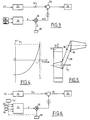
- the vehicle turns right to follow a curved trajectory 14 of radius R, this turn being effected by increasing the speed or the engine force on the left track and braking the right track, the vehicle pivots around a point located on its longitudinal axis and the ground exerts on the rollers 12 of the front and rear ends of the lateral forces which have been designated by F1g, F1d, F5g, F5d respectively in FIG. 1.
- V the linear speed of advance of the vehicle, and by ⁇ the angular speed on the curved trajectory 14.
- the behavior of the tracked vehicle when cornering depends on variations in its linear speed V, its angular speed ⁇ on its path, and its coefficient of grip on the ground.
- FIG. 2 is a diagram illustrating the domains of stable and unstable behavior of the vehicle respectively, in a system of orthogonal axes where the centripetal acceleration ⁇ V of the vehicle is plotted on the abscissa, and its linear acceleration ⁇ on the ordinate.
- the circle of radius ⁇ g represents the maximum acceleration of the vehicle on the ground, ⁇ being the coefficient of grip of the vehicle on the ground and g the acceleration of gravity.
- the hatched area A represents the area of instability of the vehicle when cornering. In this area of instability, the vehicle naturally goes into oversteer and gradually closes its trajectory. We can see in the diagram in Figure 2 that an acceleration significant would allow to get out of this area of instability, but the available power is generally insufficient, at high speed, to accelerate strongly.
- the subject of the invention is precisely means for controlling the turn of a tracked vehicle (or of a vehicle with non-steered wheels) which make it possible to cause the vehicle to comply with the advancement and turn instructions it receives. , as long as it remains in its natural stability range represented by the unshaded part inside the circle in FIG. 2, and to modify the turn setpoint when this combined with the advance setpoint would cause it to the area of instability (shaded area A).
- the invention is based essentially on the detection of the departure by oversteering of the vehicle and on the instantaneous correction of the turn command which causes this departure in oversteer.
- the control device comprises means 20 receiving a turn command 22 given by the operator or the driver of the vehicle and transforming it into a signal 24 of setpoint bend intended to be applied to means 26 for differential control of the right and left tracks of the vehicle, such as for example a hydrostatic group for direct control of the differential speed of the tracks.
- This device also includes a gyrometric sensor 28 mounted on the vehicle and producing at the output a signal ⁇ representing the instantaneous angular speed. yaw of the vehicle, this signal being applied to an input of a multiplier 30 of which another input receives an amplification coefficient or gain k produced by calculation means 32.
- the output of the multiplier 30 is connected to the negative input a subtractor circuit 34, the positive input of which receives the turn signal 24 and the output of which is connected to the input of the means 26 for the differential control of the tracks.
- a leveling amplifier can be interposed between the output of the multiplier 30 and the negative input of the subtractor 34.
- the amplification gain k of the instantaneous yaw angular speed of the vehicle is variable as a function of the conditions of movement of the vehicle, this gain having a value substantially zero in the field of stable behavior of the vehicle when cornering and rapidly increasing up to at a predetermined maximum value when approaching the area of unstable behavior of the vehicle when cornering.
- this gain k is obtained from the lateral forces exerted by the ground on the front and rear end rollers of the vehicle.
- This ratio is equal to (F1g + F1d) / (F5g + F5d) if we take the notations of Figure 1.
- this ratio will be designated in the following by F1 / F5, because it varies significantly as F1g / F5d when the vehicle turns right, F1d and F5g tending to decrease and to cancel in this case, and, conversely when the vehicle veers to the left, this ratio varies as F1d / F5g.
- this F1 / F5 ratio is represented in FIG. 4 as a function of the ⁇ / ⁇ max ratio (ratio of the instantaneous yaw angular speed of the vehicle and the maximum possible value of this speed).
- ⁇ / ⁇ max ratio ratio of the instantaneous yaw angular speed of the vehicle and the maximum possible value of this speed.
- the lateral forces exerted by the ground on the end rollers of the tracks of the vehicle can be determined by means of strain gauges 36 fixed on a suspension arm 38 of a roller 12 , the strain gauges 36 making it possible to measure the bending force to which the suspension arm 38 is subjected and to deduce therefrom by a calculation of moments the lateral force (for example F1) exerted by the ground on the roller 12, when we know the force Fa exerted on the roller by the tension of the track.
- F1 moments the lateral force
- the strain gauges 36 mounted on the suspension arms 38 of the front and rear end rollers of the vehicle provide the calculation means 32 with information making it possible to calculate the ratio of the lateral forces exerted by the ground on the front end rollers and rear of the vehicle, and to deduce therefrom the amplification gain k from the instantaneous yaw angular speed of the vehicle, supplied by the gyrometric sensor 28.
- the signal k ⁇ leaving the multiplier 30 is, after a possible upgrade, subtracted from the turn instruction signal 24 supplied by the means 20 in response to a turn command 22 given by the driver or the driver of the vehicle.
- the difference between the turn setpoint signal 24 and the signal K ⁇ is applied to the differential track control means 26, to control the turn of the vehicle.
- the amplification gain k has a value substantially zero or close to 0, and the instantaneous yaw angular speed feedback 'Has substantially no effect on the turn setpoint signal 24, which is applied as is to the control means 26.
- the vehicle then turns in accordance with the turn order given by the driver or the driver.
- the gain of amplification k has a value close to 1 or greater than 1, and the signal 24 of the setpoint setpoint is reduced by the feedback of the instantaneous yaw angular velocity of the vehicle, which amounts to automatically performing a "reverse steering" of the vehicle, which opposes its departure from oversteer and substantially maintains it on the trajectory corresponding to the order of turn given by the operator or the driver.
- FIG. 6 shows an alternative embodiment of the invention, in which the gain in amplification of the vehicle yaw angular speed is obtained, no longer from the lateral forces exerted by the ground on the front end rollers and rear of the vehicle, but from the lateral accelerations of the vehicle at the front and rear, the angular yaw acceleration of the vehicle, and the differential force applied to the tracks when cornering.
- the device then comprises two linear accelerometers 40 mounted at the front and at the rear of the vehicle to determine the lateral accelerations of the latter.
- Means 42 are also provided for measuring the differential force applied to the tracks when cornering, this differential force resulting from the differential speed control of the tracks and being obtained for example from a differential pressure when the control means 26 are of the hydraulic type.
- the output signals from the accelerometers 40 and the differential force measurement means 42 are applied to the inputs of the calculation means 32, which provide an output gain of amplification k of the instantaneous yaw angular velocity of the vehicle delivered by the gyrometric sensor 28.
- the device is identical to that of FIG. 3.
- the difference in lateral accelerations measured by the sensors at the front and rear of the vehicle makes it possible to determine the angular yaw acceleration of the vehicle, by dividing this difference by the length of the vehicle.
- the average of these two lateral accelerations provides the lateral linear acceleration of the vehicle's center of gravity.
- an angular accelerometer can be used to measure the angular yaw acceleration of the vehicle.
- a single linear accelerometer can then be used to measure the linear acceleration lateral to the center of gravity of the vehicle.
- the yaw angular speed signal of the vehicle is applied to an input of the calculation means 32 as shown in dotted lines in FIG. 6, another input of these calculation means receiving a signal representing the forward speed of the vehicle.
- Derivation of the yaw angular velocity signal provides the vehicle angular yaw acceleration and low-pass filtering of the product of the yaw angular velocity by the forward speed of the vehicle provides acceleration lateral line of the vehicle center of gravity.
- the amplification gain k being given by the same equation as a function of the lateral acceleration at the center of gravity of the vehicle, the angular yaw acceleration and the differential control effort of the caterpillars.
- This variant avoids mounting linear and / or angular accelerometers on the vehicle.
- FIG. 7 schematically represents a device according to the invention for a tracked vehicle equipped with a turn control system by controlling the differential force of the tracks, for example by means of a steering brake, the tightening of which makes it possible to adjust the differential torque of the tracks.
- This device essentially corresponds to that of FIG. 6, the calculation means 32 receiving as input a signal ⁇ representing the lateral linear acceleration of the vehicle, a signal ⁇ representing the angular yaw acceleration and a signal ⁇ F representing the differential control effort of the tracks.
- the calculation means 32 generate from these signals a gain k ′ of amplification of the instantaneous yaw angular speed provided by the gyrometric sensor 28.
- the turn setpoint signal 24 and the output signal k ⁇ of the multiplier 30 are applied to the inputs of the subtractor 34 which transmits their difference to means 44 transforming this difference (corresponding to an angular speed) into a differential force signal ⁇ F applied to the direction control system 46.
- this differential force signal ⁇ F can also be applied to the input of the calculation means 32, for determining the gain k '.
- This gain k ′ is calculated by means of the formula given for the embodiment of FIG. 6, but with a constant a ′ greater than a to reinforce the angular velocity speed feedback applied to the turn setpoint signal, a vehicle with cornering control by controlling the differential force of the tracks having an unstable behavior as soon as one leaves the area in which the cornering torque increases when the cornering tightens.
- the invention which has been described above in the case of a tracked vehicle, also applies to vehicles with non-steerable wheels.
Description
L'invention concerne un procédé et un dispositif de commande du virage d'un véhicule chenillé ou à roues non directrices.The invention relates to a method and a device for controlling the turn of a tracked or non-steered vehicle.
De façon générale, l'invention s'applique aussi bien aux véhicules de ce type pilotés par des conducteurs installés à bord des véhicules, qu'aux véhicules pilotés à distance par télécommande.In general, the invention applies as well to vehicles of this type controlled by drivers installed on board vehicles, as to vehicles controlled remotely by remote control.
Les véhicules chenillés ou à roues non directrices sont équipés de moyens de commande différentielle de leurs chenilles ou de leurs roues, qui leur permettent de virer par augmentation du couple moteur ou de la vitesse de la chenille extérieure ou des roues extérieures, et freinage de la chenille intérieure ou des roues intérieures, la vitesse du véhicule pouvant être maintenue en virage par récupération de l'énergie de freinage de la chenille intérieure ou des roues intérieures. La vitesse différentielle des chenilles ou des roues peut être pilotée directement, de façon continue ou discontinue, ce qui permet d'améliorer le contrôle du virage du véhicule.Tracked or non-steered wheeled vehicles are equipped with differential control means for their tracks or their wheels, which allow them to turn by increasing the engine torque or the speed of the outside track or outside wheels, and braking the inner track or inner wheels, the vehicle speed being able to be maintained when cornering by recovering the braking energy from the inner track or the inner wheels. The differential speed of the tracks or wheels can be controlled directly, continuously or discontinuously, which improves the control of the vehicle's turn.
Toutefois, ces moyens connus ne permettent pas de conserver le contrôle du véhicule dans un domaine de virages allant jusqu'au début d'un dérapage ou d'un survirage, en particulier à grande vitesse. Cet inconvénient, qui limite les performances d'évolution des véhicules chenillés ou à roues non directrices, est encore aggravé par le fait qu'une diminution de l'accélération du véhicule ou son freinage accentue brutalement le survirage.However, these known means do not make it possible to maintain control of the vehicle in a range of turns up to the start of a skid or oversteer, in particular at high speed. This drawback, which limits the performance of tracked or non-steered wheels, is further aggravated by the fact that a decrease in vehicle acceleration or braking brutally accentuates oversteer.
L'invention a pour objet d'augmenter les possibilités de contrôle de virage d'un véhicule chenillé ou à roues non directrices, et d'améliorer sa stabilité en virage, en particulier à l'approche d'un départ en survirage.The object of the invention is to increase the possibilities of cornering control of a tracked or non-steerable vehicle, and to improve its stability when cornering, in particular when approaching an oversteer departure.
Corollairement, l'invention a pour objet d'augmenter les performances d'évolution d'un véhicule de ce type, notamment d'un véhicule blindé à usage militaire.As a corollary, the invention aims to increase the performance of evolution of a vehicle of this type, in particular of an armored vehicle for military use.
Elle propose, à cet effet, un procédé de commande du virage d'un véhicule chenillé ou à roues non directrices, qui comprend des moyens de commande différentielle de ses chenilles ou de ses roues, ce procédé étant caractérisé en ce qu'il consiste à produire un signal de consigne de virage, destiné à être transmis aux moyens de commande précités, à partir d'un ordre de virage donné par un opérateur ou un conducteur du véhicule, à détecter la vitesse angulaire instantanée de lacet du véhicule, à amplifier avec un gain déterminé le signal représentant cette vitesse détectée, à comparer le signal amplifié au signal de consigne de virage et à transmettre leur différence aux moyens de commande précités, afin d'assurer la stabilité du virage du véhicule en effectuant automatiquement un contre-braquage à la détection d'un début de survirage du véhicule.To this end, it proposes a method for controlling the turn of a tracked or non-steered vehicle, which comprises means for differential control of its tracks or wheels, this method being characterized in that it consists of produce a turn setpoint signal, intended to be transmitted to the aforementioned control means, from a turn command given by an operator or a driver of the vehicle, to detect the instantaneous yaw angular speed of the vehicle, to be amplified with a determined gain the signal representing this detected speed, to compare the amplified signal with the turn setpoint signal and to transmit their difference to the aforementioned control means, in order to ensure the stability of the turn of the vehicle by automatically performing a reverse steering at the detection of a start of oversteering of the vehicle.
Le départ du véhicule en survirage peut être provoqué par un ordre de resserrement du virage, ou par une augmentation de la vitesse du véhicule dans un virage à rayon constant, ou encore par la diminution de l'adhérence du véhicule sur le sol, ou bien par la nécessité de devoir freiner en cours de virage.The departure of the oversteer vehicle may be caused by an order to tighten the turn, or by an increase in the speed of the vehicle in a constant radius turn, or by the decrease in the grip of the vehicle on the ground, or by the need to brake during the turn.
La mesure de la vitesse angulaire instantanée de lacet du véhicule et son amplification par un gain déterminé de façon particulière permettent de détecter le départ du véhicule en survirage et de le contrôler immédiatement par réduction de la consigne de virage donnée par le conducteur ou l'opérateur, c'est-à-dire en effectuant automatiquement un contre-braquage qui s'oppose au survirage.The measurement of the vehicle's instantaneous yaw rate and its amplification by a gain determined in a particular way makes it possible to detect the departure of the oversteer vehicle and to control it immediately by reducing the turn command given by the driver or operator , that is to say by automatically carrying out a counter-steering which opposes oversteer.
Il en résulte une augmentation très sensible des performances contrôlables d'évolution des véhicules chenillés ou à roues non directrices, notamment au niveau de leur vitesse maximale de déplacement en ligne droite ou en virage.This results in a very noticeable increase in the controllable performance performance of tracked or non-steerable vehicles, in particular at the level of their maximum speed of movement in a straight line or when cornering.
Le procédé selon l'invention est également caractérisé en ce qu'il consiste à faire varier le gain d'amplification du signal de vitesse angulaire de lacet du véhicule, ce gain ayant une valeur sensiblement nulle pour un domaine de comportement naturellement stable du véhicule en virage, et augmentant rapidement à l'approche d'un domaine de comportement instable du véhicule en virage.The method according to the invention is also characterized in that it consists in varying the amplification gain of the yaw angular speed signal of the vehicle, this gain having a value substantially zero for a range of naturally stable behavior of the vehicle in cornering, and increasing rapidly when approaching an area of unstable behavior of the vehicle when cornering.
De cette façon, l'ordre de virage donné par le conducteur ou l'opérateur du véhicule n'est sensiblement pas modifié lorsque le véhicule se déplace dans des conditions où il peut virer de façon naturellement stable, tandis que cet ordre de virage est corrigé automatiquement, de façon plus ou moins importante, lorsqu'il tend à amener le véhicule dans un domaine de comportement instable ou lorsqu'une diminution brusque de l'adhérence du véhicule sur le sol est détectée.In this way, the turning order given by the driver or the operator of the vehicle is not substantially modified when the vehicle is moving under conditions where it can turn naturally stable, while this turning order is corrected. automatically, to a greater or lesser extent, when it tends to bring the vehicle into an area of unstable behavior or when an abrupt decrease in the grip of the vehicle on the ground is detected.
Dans un premier mode de réalisation de l'invention, ce procédé consiste à déterminer le gain d'amplification précité à partir du rapport des efforts latéraux exercés par le sol sur les roues d'extrémités ou sur les galets d'extrémités des chenilles du véhicule, respectivement à l'avant et à l'arrière du véhicule.In a first embodiment of the invention, this method consists in determining the aforementioned amplification gain from the ratio of the lateral forces exerted by the ground on the end wheels or on the end rollers of the tracks of the vehicle. , respectively at the front and rear of the vehicle.
On a en effet constaté que ce rapport a une valeur minimale dans un domaine de comportement naturellement stable du véhicule en virage, et qu'il augmente rapidement jusqu'à une valeur maximale à l'approche d'un domaine d'instabilité, quelle que soit la cause de cette dernière. L'invention prévoit donc, avantageusement, d'utiliser ce rapport pour calculer le gain d'amplification de la vitesse angulaire instantanée de lacet du véhicule.It has in fact been found that this ratio has a minimum value in a naturally stable behavior domain of the vehicle when cornering, and that it increases rapidly to a maximum value when approaching a domain of instability, whatever either the cause of the latter. The invention therefore provides, advantageously, to use this ratio to calculate the amplification gain of the instantaneous yaw angular speed of the vehicle.
Selon une variante de l'invention, ce gain d'amplification peut également être déterminé à partir de l'accélération linéaire latérale du véhicule, de l'accélération angulaire de lacet et de l'effort différentiel de commande des roues ou des chenilles du véhicule en virage.According to a variant of the invention, this gain in amplification can also be determined from the lateral linear acceleration of the vehicle, the angular yaw acceleration and the differential force. for controlling the wheels or tracks of the vehicle when cornering.
Ces accélérations peuvent être mesurées directement au moyen de capteurs appropriés, ou bien être calculées à partir de la vitesse angulaire de lacet et de la vitesse d'avancement du véhicule.These accelerations can be measured directly by means of appropriate sensors, or they can be calculated from the yaw angular speed and the forward speed of the vehicle.
L'invention propose également un dispositif de commande du virage d'un véhicule chenillé ou à roues non directrices, ce véhicule comprenant des moyens de commande différentielle de ses chenilles ou de ses roues, le dispositif étant caractérisé en ce qu'il comprend des moyens de génération d'un signal de consigne de virage, correspondant à un ordre de virage donné par un opérateur ou un conducteur du véhicule, des moyens gyrométriques de détection de la vitesse angulaire instantanée de lacet du véhicule et de génération d'un signal correspondant, des moyens d'amplification de ce signal de vitesse angulaire avec un gain déterminé, et des moyens d'établissement de la différence entre le signal de consigne de virage et le signal amplifié de vitesse angulaire de lacet, cette différence étant transmise aux moyens de commande précités.The invention also provides a device for controlling the turn of a tracked or non-steered vehicle, this vehicle comprising means for differential control of its tracks or of its wheels, the device being characterized in that it comprises means generating a turn command signal, corresponding to a turn order given by an operator or a driver of the vehicle, gyrometric means for detecting the instantaneous yaw angular speed of the vehicle and generating a corresponding signal, means for amplifying this angular speed signal with a determined gain, and means for establishing the difference between the turn setpoint signal and the amplified yaw angular speed signal, this difference being transmitted to the control means cited above.
Selon une autre caractéristique de l'invention, ce dispositif comprend des moyens de génération d'un gain variable d'amplification du signal de vitesse angulaire de lacet, ce gain ayant une valeur sensiblement nulle pour un domaine de virages naturellement stables du véhicule, et augmentant rapidement à l'approche d'un domaine de virages instables du véhicule.According to another characteristic of the invention, this device comprises means for generating a variable gain of amplification of the yaw angular speed signal, this gain having a value substantially zero for a range of naturally stable turns of the vehicle, and rapidly increasing as you approach an area of unstable vehicle turns.
Les moyens de génération de gain peuvent comprendre des moyens de détermination des efforts latéraux exercés par le sol sur les roues d'extrémités ou sur les galets d'extrémités des chenilles à l'avant et l'arrière du véhicule, et des moyens de calcul du rapport de ces efforts latéraux.The gain generation means may comprise means for determining the lateral forces exerted by the ground on the end wheels or on the end rollers of the tracks at the front and rear of the vehicle, and calculation means of the ratio of these lateral forces.
Pour déterminer ces efforts latéraux, on peut utiliser par exemple des jauges de contrainte fixées sur les bras de suspension des roues et des galets des chenilles.To determine these lateral forces, one can use for example strain gauges fixed on the suspension arms of the wheels and the track rollers.
En variante, les moyens de génération de gain comprennent des moyens de détermination de l'accélération linéaire latérale du véhicule, des moyens de mesure de l'effort différentiel de commande des roues ou des chenilles du véhicule en virage, et des moyens de calcul, a partir de ces informations, d'un gain variant sensiblement comme celui obtenu à partir du rapport précité des forces latérales exercées par le sol à l'avant et à l'arrière du véhicule sur les roues d'extrémités ou les galets d'extrémités des chenilles.As a variant, the gain generation means comprise means for determining the lateral linear acceleration of the vehicle, means for measuring the differential control force of the wheels or tracks of the vehicle when cornering, and calculation means, from this information, a gain varying substantially like that obtained from the aforementioned ratio of the lateral forces exerted by the ground at the front and at the rear of the vehicle on the end wheels or the end rollers caterpillars.
On peut en particulier utiliser des accéléromètres pour mesurer les accélérations linéaires latérales à l'avant et à l'arrière du véhicule.In particular, accelerometers can be used to measure the lateral linear accelerations at the front and rear of the vehicle.
En variante, les moyens de calcul permettent de déterminer le gain à partir de la vitesse angulaire de lacet, de la vitesse d'avancement du véhicule et de l'effort différentiel de commande des roues ou des chenilles.As a variant, the calculation means make it possible to determine the gain from the yaw angular speed, the forward speed of the vehicle and the differential effort for controlling the wheels or the tracks.
L'invention sera mieux comprise et d'autres caractéristiques, détails et avantages de celle-ci apparaitront plus clairement à la lecture de la description qui suit, faite en référence aux dessins annexés, dans lesquels :
- la figure 1 est une vue très schématique de dessus d'un véhicule chenillé, en virage à droite;
- la figure 2 est un diagramme représentant les domaines de stabilité et d'instabilité du véhicule en virage,
- la figure 3 représente schématiquement un dispositif selon l'invention pour le contrôle de virage du véhicule;
- la figure 4 est un graphe représentant la variation du rapport des forces latérales exercées par le sol sur les galets d'extrémités avant et arrière des chenilles du véhicule;
- la figure 5 représente schématiquement un bras de suspension d'un galet du véhicule;
- les figures 6 et 7 représentent schématiquement des variantes du dispositif selon l'invention.
- Figure 1 is a very schematic top view of a tracked vehicle, in a right turn;
- FIG. 2 is a diagram representing the areas of stability and instability of the vehicle when cornering,
- FIG. 3 schematically represents a device according to the invention for controlling the turn of the vehicle;
- FIG. 4 is a graph showing the variation in the ratio of the lateral forces exerted by the ground on the front and rear end rollers of the tracks of the vehicle;
- FIG. 5 schematically represents a suspension arm of a roller of the vehicle;
- Figures 6 and 7 schematically show variants of the device according to the invention.
On a représenté très schématiquement en figure 1 un véhicule chenillé 10 qui, de façon classique, comporte deux rangées de galets 12 par lesquels il repose sur les brins inférieurs des chenilles, qui sont elles-mêmes entraînées par des barbotins. Quand le véhicule vire à droite pour suivre une trajectoire courbe 14 de rayon R, ce virage étant effectué par augmentation de la vitesse ou de l'effort moteur sur la chenille de gauche et freinage de la chenille droite, le véhicule pivote autour d'un point situé sur son axe longitudinal et le sol exerce sur les galets 12 d'extrémités avant et arrière des efforts latéraux que l'on a désigné par F1g, F1d, F5g, F5d respectivement en figure 1. Dans cette figure, on a également représenté schématiquement par V la vitesse linéaire d'avancement du véhicule, et par Ω la vitesse angulaire sur la trajectoire courbe 14.There is shown very schematically in Figure 1 a tracked
De façon générale, le comportement du véhicule chenillé en virage dépend des variations de sa vitesse linéaire V, de sa vitesse angulaire Ω sur sa trajectoire, et de son coefficient µ d'adhérence au sol.In general, the behavior of the tracked vehicle when cornering depends on variations in its linear speed V, its angular speed Ω on its path, and its coefficient of grip on the ground.
La figure 2 est un diagramme illustrant les domaines de comportements stable et instable respectivement du véhicule, dans un système d'axes orthogonaux où l'accélération centripète Ω V du véhicule est portée en abscisse, et son accélération linéaire γ en ordonnée. Le cercle de rayon µg représente l'accélération maximale du véhicule sur le sol, µ étant le coefficient d'adhérence du véhicule sur le sol et g l'accélération de la pesanteur. A l'intérieur de ce cercle, la zone hachurée A représente le domaine d'instabilité du véhicule en virage. Dans ce domaine d'instabilité, le véhicule part naturellement en survirage et referme progressivement sa trajectoire. On voit sur le diagramme de la figure 2 qu'une accélération importante permettrait de sortir de ce domaine d'instabilité, mais la puissance disponible est en général insuffisante, à vitesse élevée, pour accélérer fortement.FIG. 2 is a diagram illustrating the domains of stable and unstable behavior of the vehicle respectively, in a system of orthogonal axes where the centripetal acceleration Ω V of the vehicle is plotted on the abscissa, and its linear acceleration γ on the ordinate. The circle of radius µg represents the maximum acceleration of the vehicle on the ground, µ being the coefficient of grip of the vehicle on the ground and g the acceleration of gravity. Within this circle, the hatched area A represents the area of instability of the vehicle when cornering. In this area of instability, the vehicle naturally goes into oversteer and gradually closes its trajectory. We can see in the diagram in Figure 2 that an acceleration significant would allow to get out of this area of instability, but the available power is generally insufficient, at high speed, to accelerate strongly.
On voit également sur le diagramme de la figure 2 qu'un freinage du véhicule à l'approche du domaine d'instabilité déplace le point de fonctionnement du véhicule dans le domaine instable et provoque un départ en survirage. Il en est de même si, au cours d'un virage, le coefficient d'adhérence du véhicule sur le sol diminue brusquement.It can also be seen in the diagram in FIG. 2 that braking of the vehicle when approaching the area of instability displaces the operating point of the vehicle in the unstable area and causes a departure into oversteer. It is the same if, during a turn, the coefficient of grip of the vehicle on the ground decreases suddenly.
L'invention a précisément pour objet des moyens de commande du virage d'un véhicule chenillé (ou d'un véhicule à roues non directrices) qui permettent d'amener le véhicule à respecter les consignes d'avancement et de virage qu'il reçoit, tant qu'il reste dans son domaine de stabilité naturelle représenté par la partie non hachurée à l'intérieur du cercle en figure 2, et de modifier la consigne de virage lorsque celle-ci combinée à la consigne d'avancement l'entraînerait dans le domaine d'instabilité (zone hachurée A).The subject of the invention is precisely means for controlling the turn of a tracked vehicle (or of a vehicle with non-steered wheels) which make it possible to cause the vehicle to comply with the advancement and turn instructions it receives. , as long as it remains in its natural stability range represented by the unshaded part inside the circle in FIG. 2, and to modify the turn setpoint when this combined with the advance setpoint would cause it to the area of instability (shaded area A).
L'invention est basée essentiellement sur la détection du départ en survirage du véhicule et sur la correction instantanée de la consigne de virage qui provoque ce départ en survirage.The invention is based essentially on the detection of the departure by oversteering of the vehicle and on the instantaneous correction of the turn command which causes this departure in oversteer.
Le dispositif de commande selon l'invention, dont un exemple de réalisation est représenté en figure 3, comprend des moyens 20 recevant un ordre de virage 22 donné par l'opérateur ou le conducteur du véhicule et le transformant en un signal 24 de consigne de virage destiné à être appliqué à des moyens 26 de commande différentielle des chenilles droite et gauche du véhicule, tels par exemple qu'un groupe hydrostatique de commande directe de la vitesse différentielle des chenilles.The control device according to the invention, an exemplary embodiment of which is shown in FIG. 3, comprises
Ce dispositif comprend également un capteur gyrométrique 28 monté sur le véhicule et produisant en sortie un signal Ω représentant la vitesse angulaire instantanée de lacet du véhicule, ce signal étant appliqué à une entrée d'un multiplicateur 30 dont une autre entrée reçoit un coefficient ou gain d'amplification k produit par des moyens de calcul 32. La sortie du multiplicateur 30 est reliée à l'entrée négative d'un circuit soustracteur 34, dont l'entrée positive reçoit le signal 24 de consigne de virage et dont la sortie est reliée à l'entrée des moyens 26 de commande différentielle des chenilles. Eventuellement, et comme représenté en pointillés, un amplificateur de mise à niveau peut être interposé entre la sortie du multiplicateur 30 et l'entrée négative du soustracteur 34.This device also includes a
Avantageusement, le gain d'amplification k de la vitesse angulaire instantanée de lacet du véhicule est variable en fonction des conditions de déplacement du véhicule, ce gain ayant une valeur sensiblement nulle dans le domaine de comportement stable du véhicule en virage et augmentant rapidement jusqu'à une valeur maximale prédéterminée à l'approche du domaine de comportement instable du véhicule en virage.Advantageously, the amplification gain k of the instantaneous yaw angular speed of the vehicle is variable as a function of the conditions of movement of the vehicle, this gain having a value substantially zero in the field of stable behavior of the vehicle when cornering and rapidly increasing up to at a predetermined maximum value when approaching the area of unstable behavior of the vehicle when cornering.
Dans un premier mode de réalisation de l'invention, ce gain k est obtenu à partir des efforts latéraux exercés par le sol sur les galets d'extrémités avant et arrière du véhicule.In a first embodiment of the invention, this gain k is obtained from the lateral forces exerted by the ground on the front and rear end rollers of the vehicle.
Ce rapport est égal à ![]()
![]()
La variation de ce rapport F1/F5 est représentée en figure 4 en fonction du rapport Ω/Ωmax (rapport de la vitesse angulaire instantanée de lacet du véhicule et de la valeur maximale possible de cette vitesse). On voit que ce rapport F1/F5 est approximativement égal à -1 quand le véhicule se déplace en ligne droite, qu'il passe par une valeur nulle quand la vitesse angulaire de lacet du véhicule est égale à environ 80% de sa valeur maximale, et qu'il tend vers 1 au voisinage de la valeur maximale de la vitesse angulaire de lacet du véhicule.The variation of this F1 / F5 ratio is represented in FIG. 4 as a function of the Ω / Ωmax ratio (ratio of the instantaneous yaw angular speed of the vehicle and the maximum possible value of this speed). We can see that this F1 / F5 ratio is approximately equal to -1 when the vehicle is traveling in a straight line, passing by a zero value when the vehicle's yaw rate is equal to about 80% of its maximum value, and it tends to 1 near the maximum value of the vehicle's yaw rate.
Le gain k d'amplification de la vitesse angulaire instantanée de lacet du véhicule est donné par la relation ![]()
![]()
Comme on l'a représenté schématiquement en figure 5, les efforts latéraux exercés par le sol sur les galets d'extrémités des chenilles du véhicule peuvent être déterminés au moyen de jauges de contrainte 36 fixées sur un bras de suspension 38 d'un galet 12, les jauges de contrainte 36 permettant de mesurer l'effort de flexion auquel est soumis le bras de suspension 38 et d'en déduire par un calcul de moments la force latérale (par exemple F1) exercée par le sol sur le galet 12, quand on connaît la force Fa exercée sur le galet par la tension de la chenille.As shown diagrammatically in FIG. 5, the lateral forces exerted by the ground on the end rollers of the tracks of the vehicle can be determined by means of
Le dispositif décrit en référence aux figures 3 à 5 fonctionne donc de la façon suivante :
les jauges de contrainte 36 montées sur les bras de suspension 38 des galets d'extrémités avant et arrière du véhicule fournissent aux moyens de calcul 32 des informations permettant de calculer le rapport des efforts latéraux exercés par le sol sur les galets d'extrémités avant et arrière du véhicule, et d'en déduire le gain d'amplification k de la vitesse angulaire instantanée de lacet du véhicule, fournie par le capteur gyrométrique 28. Le signal kΩ sortant du multiplicateur 30 est, après une éventuelle mise à niveau, soustrait du signal 24 de consigne de virage fourni par les moyens 20 en réponse à un ordre de virage 22 donné par le conducteur ou le pilote du véhicule. La différence entre le signal 24 de consigne de virage et le signal KΩ est appliquée aux moyens 26 de commande différentielle des chenilles, pour contrôler le virage du véhicule.The device described with reference to FIGS. 3 to 5 therefore operates as follows:
the strain gauges 36 mounted on the
Lorsque les conditions de déplacement du véhicule sont telles qu'il se trouve dans son domaine de stabilité naturelle en virage, le gain d'amplification k a une valeur sensiblement nulle ou voisine de 0, et la contre-réaction de vitesse angulaire instantanée de lacet n'a sensiblement pas d'effet sur le signal 24 de consigne de virage, qui est appliqué tel quel aux moyens de commande 26. Le véhicule vire alors conformément à l'ordre de virage donné par le pilote ou le conducteur.When the conditions of movement of the vehicle are such that it is in its range of natural stability when cornering, the amplification gain k has a value substantially zero or close to 0, and the instantaneous yaw angular speed feedback 'Has substantially no effect on the
Par contre, si les conditions sont telles que l'on approche du domaine de comportement instable du véhicule en virage, le gain d'amplification k a une valeur voisine de 1 ou supérieure à 1, et le signal 24 de consigne de virage est réduit par la contre-réaction de la vitesse angulaire instantanée de lacet du véhicule, ce qui revient à effectuer automatiquement un "contre-braquage" du véhicule, qui s'oppose à son départ en survirage et le maintient sensiblement sur la trajectoire correspondant à l'ordre de virage donné par l'opérateur ou le conducteur.On the other hand, if the conditions are such that one approaches the area of unstable behavior of the vehicle when cornering, the gain of amplification k has a value close to 1 or greater than 1, and the
On a représenté en figure 6 une variante de réalisation de l'invention, dans laquelle le gain d'amplification de la vitesse angulaire de lacet du véhicule est obtenu, non plus à partir des efforts latéraux exercés par le sol sur les galets extrêmes avant et arrière du véhicule, mais à partir des accélérations latérales du véhicule à l'avant et à l'arrière, de l'accélération angulaire de lacet du véhicule, et de l'effort différentiel appliqué aux chenilles en virage.FIG. 6 shows an alternative embodiment of the invention, in which the gain in amplification of the vehicle yaw angular speed is obtained, no longer from the lateral forces exerted by the ground on the front end rollers and rear of the vehicle, but from the lateral accelerations of the vehicle at the front and rear, the angular yaw acceleration of the vehicle, and the differential force applied to the tracks when cornering.
Le dispositif comprend alors deux accéléromètres linéaires 40 montés à l'avant et à l'arrière du véhicule pour déterminer les accélérations latérales de celui-ci. Des moyens 42 sont également prévus pour mesurer l'effort différentiel appliqué aux chenilles en virage, cet effort différentiel résultant de la commande de vitesse différentielle des chenilles et étant obtenu par exemple à partir d'une pression différentielle quand les moyens de commande 26 sont du type hydraulique.The device then comprises two
Les signaux de sortie des accéléromètres 40 et des moyens 42 de mesure de l'effort différentiel sont appliqués aux entrées des moyens de calcul 32, qui fournissent en sortie un gain d'amplification k de la vitesse angulaire instantanée de lacet du véhicule délivrée par le capteur gyrométrique 28. Pour le reste, le dispositif est identique à celui de la figure 3.The output signals from the
La différence des accélérations latérales mesurées par les capteurs à l'avant et à l'arrière du véhicule permet de déterminer l'accélération angulaire de lacet du véhicule, par division de cette différence par la longueur du véhicule.The difference in lateral accelerations measured by the sensors at the front and rear of the vehicle makes it possible to determine the angular yaw acceleration of the vehicle, by dividing this difference by the length of the vehicle.
La moyenne de ces deux accélérations latérales fournit l'accélération linéaire latérale du centre de gravité du véhicule.The average of these two lateral accelerations provides the lateral linear acceleration of the vehicle's center of gravity.
Les relations suivantes permettent de déterminer le gain k d'amplification de la vitesse angulaire instantanée de lacet du véhicule :
![]()
![]()
![]()
avec
ÿ1 = accélération linéaire latérale à l'avant du véhicule
ÿ5 = accélération linéaire latérale à l'arrière du véhicule
L = longueur du véhicule
Ω̇ = accélération angulaire de lacet
ÿ = accélération linéaire latérale au centre de gravité du véhicule
M = masse du véhicule
d = distance entre les axes de deux galets consécutifs
I = inertie de lacet du véhicule
ΔF = effort différentiel appliqué aux chenilles
D = distance entre les axes des chenilles
a = constante
Ce gain varie sensiblement comme celui obtenu à partir du rapport F1/F5 dans le premier mode de réalisation de l'invention.The following relationships are used to determine the gain k of amplification of the vehicle's instantaneous yaw rate:
![]()
![]()
![]()
with
ÿ1 = lateral linear acceleration at the front of the vehicle
ÿ5 = lateral linear acceleration at the rear of the vehicle
L = vehicle length
Ω̇ = angular yaw acceleration
ÿ = lateral linear acceleration at the vehicle center of gravity
M = vehicle mass
d = distance between the axes of two consecutive rollers
I = vehicle yaw inertia
ΔF = differential force applied to the tracks
D = distance between the axes of the tracks
a = constant
This gain varies significantly like that obtained from the F1 / F5 ratio in the first embodiment of the invention.
En variante, on peut utiliser un accéléromètre angulaire pour mesurer l'accélération angulaire de lacet du véhicule. On peut alors utiliser un seul accéléromètre linéaire pour mesurer l'accélération linéaire latérale au centre de gravité du véhicule.Alternatively, an angular accelerometer can be used to measure the angular yaw acceleration of the vehicle. A single linear accelerometer can then be used to measure the linear acceleration lateral to the center of gravity of the vehicle.
Selon une autre variante de réalisation de l'invention, il est également possible de calculer le gain d'amplification k à partir de la vitesse angulaire de lacet du véhicule fournie par le capteur gyrométrique 28, de la vitesse d'avancement du véhicule, et de l'effort différentiel appliqué aux chenilles. Dans ce cas, le signal de vitesse angulaire de lacet du véhicule est appliqué à une entrée des moyens de calcul 32 comme représenté en traits pointillés en figure 6, une autre entrée de ces moyens de calcul recevant un signal représentant la vitesse d'avancement du véhicule. La dérivation du signal de vitesse angulaire de lacet permet d'obtenir l'accélération angulaire de lacet du véhicule et le filtrage passe-bas du produit de la vitesse angulaire de lacet par la vitesse d'avancement du véhicule permet d'obtenir l'accélération linéaire latérale du centre de gravité du véhicule. On est ainsi ramené au cas précédent, le gain d'amplification k étant donné par la même équation en fonction de l'accélération latérale au centre de gravité du véhicule, de l'accélération angulaire de lacet et de l'effort différentiel de commande des chenilles. Cette variante évite de monter des accéléromètres linéaires et/ou angulaires sur le véhicule.According to another variant embodiment of the invention, it is also possible to calculate the amplification gain k from the angular yaw speed of the vehicle provided by the
La figure 7 représente schématiquement un dispositif selon l'invention pour un véhicule chenillé équipé d'un système de commande de virage par pilotage de l'effort différentiel des chenilles, par exemple au moyen d'un frein de direction dont le serrage permet de régler le couple différentiel des chenilles.FIG. 7 schematically represents a device according to the invention for a tracked vehicle equipped with a turn control system by controlling the differential force of the tracks, for example by means of a steering brake, the tightening of which makes it possible to adjust the differential torque of the tracks.
Ce dispositif selon l'invention correspond pour l'essentiel à celui de la figure 6, les moyens de calcul 32 recevant en entrée un signal ÿ représentant l'accélération linéaire latérale du véhicule, un signal Ω̇ représentant l'accélération angulaire de lacet et un signal ΔF représentant l'effort différentiel de commande des chenilles. Les moyens de calcul 32 génèrent à partir de ces signaux un gain k' d'amplification de la vitesse angulaire instantanée de lacet fournie par le capteur gyrométrique 28. Le signal 24 de consigne de virage et le signal k' Ω de sortie du multiplicateur 30 sont appliqués aux entrées du soustracteur 34 qui transmet leur différence à des moyens 44 transformant cette différence (correspondant à une vitesse angulaire) en un signal d'effort différentiel ΔF appliqué au système 46 de commande de direction.This device according to the invention essentially corresponds to that of FIG. 6, the calculation means 32 receiving as input a signal ÿ representing the lateral linear acceleration of the vehicle, a signal Ω̇ representing the angular yaw acceleration and a signal ΔF representing the differential control effort of the tracks. The calculation means 32 generate from these signals a gain k ′ of amplification of the instantaneous yaw angular speed provided by the
Comme représenté en figure 7, ce signal d'effort différentiel ΔF peut également être appliqué à l'entrée des moyens de calcul 32, pour la détermination du gain k'.As shown in FIG. 7, this differential force signal ΔF can also be applied to the input of the calculation means 32, for determining the gain k '.
Ce gain k' est calculé au moyen de la formule donnée pour le mode de réalisation de la figure 6, mais avec une constante a' supérieure à a pour renforcer la contre-réaction de vitesse angulaire de lacet appliquée au signal de consigne de virage, un véhicule à commande de virage par pilotage de l'effort différentiel des chenilles ayant un comportement instable dès que l'on sort du domaine dans lequel le couple de virage augmente lorsque le virage se resserre.This gain k ′ is calculated by means of the formula given for the embodiment of FIG. 6, but with a constant a ′ greater than a to reinforce the angular velocity speed feedback applied to the turn setpoint signal, a vehicle with cornering control by controlling the differential force of the tracks having an unstable behavior as soon as one leaves the area in which the cornering torque increases when the cornering tightens.
L'invention, qui a été décrite ci-dessus dans le cas d'un véhicule chenillé, s'applique également aux véhicules à roues non directrices.The invention, which has been described above in the case of a tracked vehicle, also applies to vehicles with non-steerable wheels.
Claims (16)
- A method of controlling the steering of a vehicle that is tracked or that has non-steerable wheels, the vehicle including differential control means (26, 46) for applying differential control to the tracks or to the wheels, the method being characterized in that it consists in producing a steering command signal (24) for application to the above-mentioned control means (26, 26) on the basis of a steering instruction (22) given by an operator or a driver of the vehicle, in detecting the instantaneous angular velocity in yaw of the vehicle, in amplifying with determined gain the signal representative of said detected velocity, in comparing the signal amplified in this way with the steering command signal (24), and in transmitting the difference between them to the above-mentioned control means (26, 46) in order to ensure that the vehicle is stable while turning by automatically applying a steering correction on detecting the beginning of vehicle oversteer.
- A method according to claim 1, characterized in that it consists in causing the gain with which the signal representative of angular velocity in yaw is amplified to vary such that such steering gain has a value of substantially zero for a range in which the behavior of the vehicle is naturally stable, which value increases rapidly on coming close to a range in which the steering behavior of the vehicle is unstable.
- A method according to claim 1 or 2, characterized in that it consists in determining the amplification gain applied to the signal representative of angular velocity in yaw on the basis of the ratio of the sideways forces (F1, F5) exerted by the ground on the wheels or the track wheels at opposite ends of the vehicle, respectively at the front of the vehicle and at the back of the vehicle.
- A method according to claim 3, characterized in that it consists in determining the above-mentioned sideways forces (F1, F5) by measuring the bending forces in the suspension arms (38) for the wheels or track wheels at the ends of the vehicle.
- A method according to claim 1 or 2, characterized in that it consists in determining the above-mentioned amplification gain on the basis of the sideways linear acceleration of the vehicle, of its angular acceleration in yaw, and of the force differential for controlling the wheels or the tracks of the vehicle while steering.
- A method according to claim 5, characterized in that it consists in measuring the lateral linear accelerations at the front and at the back of the vehicle, and in deducing therefrom by calculation the sideways linear acceleration of the center of gravity of the vehicle, and the angular acceleration in yaw of the vehicle.
- A method according to claim 5, characterized in that it consists in detecting and in measuring the sideways linear acceleration of the center of gravity of the vehicle and the angular acceleration in yaw of the vehicle.
- A method according to any preceding claim, characterized in that it consists in measuring the instantaneous angular velocity in yaw of the vehicle, by means of a rate gyro sensor.
- Apparatus for controlling the steering of a vehicle that has tracks or non-steerable wheels, the vehicle including differential control means (26, 46) for controlling its tracks or its wheels, said apparatus being characterized in that it comprises means (20) for generating a steering command signal (24) corresponding to a steering instruction (22) given by an operator or a driver, rate gyro means (28) for detecting the instantaneous angular velocity in yaw of the vehicle and for generating a corresponding signal, means (30) for amplifying said angular velocity in yaw signal by a determined gain, and means (30) for establishing the difference between the steering command signal and the amplified angular velocity in yaw signal, said difference between transmitted to the above-mentioned control means (26, 46), in order to ensure that the vehicle is stable in steering by automatically applying a steering correction on detecting the beginning of vehicle oversteer.
- Apparatus according to claim 9, characterized in that it includes gain generation means (32) for generating a variable amplification gain for application to the angular velocity signal in yaw, said gain having a value of substantially zero for a range in which the steering of the vehicle is naturally stable, and increasing rapidly on approaching a range in which the steering of the vehicle is unstable.
- Apparatus according to claim 10, characterized in that the gain generation means comprise means (32, 36) for determining the sideways forces (F1, F5) exerted by the ground on the wheels or the track wheels at the front and at the back ends of the vehicle, and for calculating the ratio of said sideways forces at the front and at the back of the vehicle.
- Apparatus according to claim 11, characterized in that the means for determining said sideways forces (F1, F5) comprise strain gauges (36) fixed to the suspension arms (38) for the wheels or the track wheels.
- Apparatus according to claim 10, characterized in that the gain generation means comprise means for determining or for measuring the sideways linear acceleration of the vehicle and its angular acceleration in yaw, means (42) for measuring the differential control force applied to the wheels or the tracks of the vehicle while steering, and means (32) to calculate an amplification gain on the basis of the sideways linear acceleration, of the angular acceleration in yaw, and of the differential control force applied to the wheels or of the tracks.
- Apparatus according to claim 13, characterized in that it includes at least one accelerometer (40) for measuring said sideways linear acceleration of the vehicle.
- Apparatus according to claim 13 or 14, characterized in that it includes an accelerometer for measuring the angular acceleration in yaw of the vehicle.
- Apparatus according to claim 13, characterized in that the calculation means (32) are designed to determine said sideways linear acceleration of the vehicle and its angular acceleration in yaw on the basis of its angular velocity in yaw and of its forwards speed.
Priority Applications (4)
| Application Number | Priority Date | Filing Date | Title |
|---|---|---|---|
| FR9111256A FR2681449B1 (en) | 1991-09-12 | 1991-09-12 | METHOD AND DEVICE FOR CONTROLLING THE TURNING OF A CRAWLER VEHICLE OR WITH NON-STEERING WHEELS. |
| EP92403080A EP0598155B1 (en) | 1991-09-12 | 1992-11-17 | Turn controlling method and device for vehicle with non-steered wheels or tracks |
| DE1992611995 DE69211995T2 (en) | 1992-11-17 | 1992-11-17 | Steering method and device for cornering control of a vehicle with non-steered wheels or with crawler tracks |
| US07/978,861 US5307888A (en) | 1991-09-12 | 1992-11-19 | Method and apparatus for controlling the steering of a vehicle that is tracked or that has non-steerable wheels |
Applications Claiming Priority (3)
| Application Number | Priority Date | Filing Date | Title |
|---|---|---|---|
| FR9111256A FR2681449B1 (en) | 1991-09-12 | 1991-09-12 | METHOD AND DEVICE FOR CONTROLLING THE TURNING OF A CRAWLER VEHICLE OR WITH NON-STEERING WHEELS. |
| EP92403080A EP0598155B1 (en) | 1991-09-12 | 1992-11-17 | Turn controlling method and device for vehicle with non-steered wheels or tracks |
| US07/978,861 US5307888A (en) | 1991-09-12 | 1992-11-19 | Method and apparatus for controlling the steering of a vehicle that is tracked or that has non-steerable wheels |
Publications (2)
| Publication Number | Publication Date |
|---|---|
| EP0598155A1 EP0598155A1 (en) | 1994-05-25 |
| EP0598155B1 true EP0598155B1 (en) | 1996-07-03 |
Family
ID=27234874
Family Applications (1)
| Application Number | Title | Priority Date | Filing Date |
|---|---|---|---|
| EP92403080A Expired - Lifetime EP0598155B1 (en) | 1991-09-12 | 1992-11-17 | Turn controlling method and device for vehicle with non-steered wheels or tracks |
Country Status (3)
| Country | Link |
|---|---|
| US (1) | US5307888A (en) |
| EP (1) | EP0598155B1 (en) |
| FR (1) | FR2681449B1 (en) |
Families Citing this family (48)
| Publication number | Priority date | Publication date | Assignee | Title |
|---|---|---|---|---|
| FR2681449B1 (en) * | 1991-09-12 | 1993-12-10 | Giat Industries | METHOD AND DEVICE FOR CONTROLLING THE TURNING OF A CRAWLER VEHICLE OR WITH NON-STEERING WHEELS. |
| US6039133A (en) * | 1997-11-17 | 2000-03-21 | Zulu; Joshua | Steering control system for an articulating work machine having a steering fluid cylinder and a fluid-powered differential |
| US6148939A (en) * | 1998-12-22 | 2000-11-21 | Caterpillar Inc. | Variable gain steering control system for a work machine |
| US7275607B2 (en) | 1999-06-04 | 2007-10-02 | Deka Products Limited Partnership | Control of a personal transporter based on user position |
| US6202773B1 (en) * | 1999-07-30 | 2001-03-20 | Invacare Corporation | Motorized wheelchairs |
| US6445990B1 (en) | 2001-03-19 | 2002-09-03 | Caterpillar Inc. | Method and apparatus for controlling straight line travel of a tracked machine |
| AU2003247972A1 (en) | 2002-07-12 | 2004-02-02 | Deka Products Limited Partnership | Control of a transporter based on attitude |
| DE60327260D1 (en) * | 2003-02-11 | 2009-05-28 | Nexter Systems | METHOD FOR REDUCING THE SPEED OF A VEHICLE IN CURVES |
| US7165644B2 (en) * | 2004-03-18 | 2007-01-23 | Ford Global Technologies, Llc | Method and apparatus of controlling an automotive vehicle using brake-steer as a function of steering wheel torque |
| US20050206231A1 (en) * | 2004-03-18 | 2005-09-22 | Ford Global Technologies, Llc | Method and apparatus for controlling an automotive vehicle using brake-steer and normal load adjustment |
| US7229139B2 (en) * | 2004-03-18 | 2007-06-12 | Ford Global Technologies, Llc | Control system for brake-steer assisted parking and method therefor |
| US8380416B2 (en) | 2004-03-18 | 2013-02-19 | Ford Global Technologies | Method and apparatus for controlling brake-steer in an automotive vehicle in reverse |
| US7690737B2 (en) * | 2004-03-18 | 2010-04-06 | Ford Global Technologies | Method of controlling an automotive vehicle having a trailer |
| US7441623B2 (en) * | 2005-02-28 | 2008-10-28 | Caterpillar Inc. | Multi-motor drive system for a work machine |
| JP2006321271A (en) * | 2005-05-17 | 2006-11-30 | Jtekt Corp | Steering gear for vehicle |
| US8061459B2 (en) * | 2006-01-17 | 2011-11-22 | GM Global Technology Operations LLC | Traction control method for a tracked vehicle |
| JP4876617B2 (en) * | 2006-02-17 | 2012-02-15 | 日産自動車株式会社 | Vehicle behavior control device |
| KR101107538B1 (en) * | 2006-03-15 | 2012-02-08 | 퀄컴 인코포레이티드 | Sensor-based orientation system |
| US20070256884A1 (en) * | 2006-05-03 | 2007-11-08 | Deere & Company, A Delaware Corporation | Stable steering control system |
| US7942220B2 (en) * | 2006-12-22 | 2011-05-17 | Caterpillar Inc. | Differential steering control for a continuously variable transmission machine |
| EP1972486A1 (en) | 2007-03-19 | 2008-09-24 | Invacare International Sàrl | Motorized wheelchair |
| US8315770B2 (en) * | 2007-11-19 | 2012-11-20 | Invacare Corporation | Motorized wheelchair |
| FR2931437A1 (en) * | 2008-05-22 | 2009-11-27 | Nexter Systems | Turning control method for tracked or non-steering wheel vehicle, involves providing threshold to implement correction of locking such that unlocking is not carried out, when linear speed and/or yaw speed of vehicle are with less amplitude |
| FR2931436B1 (en) | 2008-05-23 | 2010-10-08 | Nexter Systems | DEVICE FOR CONTROLLING ACTIVE DIRECTION. |
| FR2943027B1 (en) * | 2009-03-11 | 2012-12-28 | Motor Dev Internat Sa | MOTOR VEHICLE HAVING ENERGY RECOVERED BRAKE CHANGE SYSTEM |
| US9321591B2 (en) | 2009-04-10 | 2016-04-26 | Symbotic, LLC | Autonomous transports for storage and retrieval systems |
| US9694975B2 (en) | 2009-04-10 | 2017-07-04 | Symbotic, LLC | Lift interface for storage and retrieval systems |
| GB2478957B (en) * | 2010-03-24 | 2014-07-09 | Penny & Giles Controls Ltd | A controller and control method for a motorised vehicle |
| GB2478956B (en) * | 2010-03-24 | 2015-04-22 | Penny & Giles Controls Ltd | A controller and control method for a motorised vehicle |
| GB2484467B (en) | 2010-10-11 | 2015-07-22 | Penny & Giles Controls Ltd | A controller and control method for a motorised vehicle |
| US9499338B2 (en) | 2010-12-15 | 2016-11-22 | Symbotic, LLC | Automated bot transfer arm drive system |
| US9187244B2 (en) | 2010-12-15 | 2015-11-17 | Symbotic, LLC | BOT payload alignment and sensing |
| US11078017B2 (en) | 2010-12-15 | 2021-08-03 | Symbotic Llc | Automated bot with transfer arm |
| US8696010B2 (en) | 2010-12-15 | 2014-04-15 | Symbotic, LLC | Suspension system for autonomous transports |
| US9561905B2 (en) | 2010-12-15 | 2017-02-07 | Symbotic, LLC | Autonomous transport vehicle |
| US8965619B2 (en) | 2010-12-15 | 2015-02-24 | Symbotic, LLC | Bot having high speed stability |
| US9022487B2 (en) * | 2011-08-11 | 2015-05-05 | Cnh Industrial America Llc | System and method for brake assisted turning |
| KR102473726B1 (en) | 2013-09-13 | 2022-12-02 | 심보틱 엘엘씨 | Automated storage and retrieval system |
| US10926756B2 (en) | 2016-02-23 | 2021-02-23 | Deka Products Limited Partnership | Mobility device |
| US10908045B2 (en) | 2016-02-23 | 2021-02-02 | Deka Products Limited Partnership | Mobility device |
| US11399995B2 (en) | 2016-02-23 | 2022-08-02 | Deka Products Limited Partnership | Mobility device |
| PT3420417T (en) | 2016-02-23 | 2023-05-04 | Deka Products Lp | Mobility device control system |
| DK3443426T3 (en) | 2016-04-14 | 2023-01-23 | Deka Products Lp | TRANSPORT VESSEL AND A METHOD OF CONTROLLING A TRANSPORT VESSEL |
| US10864127B1 (en) | 2017-05-09 | 2020-12-15 | Pride Mobility Products Corporation | System and method for correcting steering of a vehicle |
| USD829612S1 (en) | 2017-05-20 | 2018-10-02 | Deka Products Limited Partnership | Set of toggles |
| USD846452S1 (en) | 2017-05-20 | 2019-04-23 | Deka Products Limited Partnership | Display housing |
| WO2019237031A1 (en) | 2018-06-07 | 2019-12-12 | Deka Products Limited Partnership | System and method for distributed utility service execution |
| DE102020111246A1 (en) * | 2020-04-24 | 2021-10-28 | Claas Tractor Sas | Drift compensation |
Family Cites Families (10)
| Publication number | Priority date | Publication date | Assignee | Title |
|---|---|---|---|---|
| FR2486881A1 (en) * | 1980-07-18 | 1982-01-22 | Jarret Jean | TERRESTRIAL VEHICLE WITH ELECTRONIC CONTROL AND DRIVING METHOD THEREFOR |
| FR2549433B1 (en) * | 1983-07-20 | 1985-11-08 | Jarret Jean Marie | VEHICLE GUIDED BY THE INDIVIDUAL TORQUE APPLIED TO ITS DRIVE WHEELS, AND METHOD FOR TURNING SUCH A VEHICLE |
| US4520299A (en) * | 1983-12-22 | 1985-05-28 | General Electric Company | Turning speed controller for electric vehicles having dual drive motors |
| US4761022A (en) * | 1986-03-08 | 1988-08-02 | Toyota Jidosha Kabushiki Kaisha | Suspension controller for improved turning |
| JPS62227819A (en) * | 1986-03-28 | 1987-10-06 | Toyota Autom Loom Works Ltd | Pitching abatement method for skid steering vehicle |
| DE3619401C2 (en) * | 1986-06-09 | 1999-03-18 | Linde Ag | Control device for a vehicle with differential speed steering |
| US4914592A (en) * | 1987-12-03 | 1990-04-03 | Trw Inc. | Apparatus for controlling a steering-by-driving system |
| JP2797189B2 (en) * | 1988-12-02 | 1998-09-17 | 本田技研工業株式会社 | Vehicle turning motion control device |
| US5101919A (en) * | 1990-08-15 | 1992-04-07 | Avco Corporation | Steering system for tracked vehicles |
| FR2681449B1 (en) * | 1991-09-12 | 1993-12-10 | Giat Industries | METHOD AND DEVICE FOR CONTROLLING THE TURNING OF A CRAWLER VEHICLE OR WITH NON-STEERING WHEELS. |
-
1991
- 1991-09-12 FR FR9111256A patent/FR2681449B1/en not_active Expired - Lifetime
-
1992
- 1992-11-17 EP EP92403080A patent/EP0598155B1/en not_active Expired - Lifetime
- 1992-11-19 US US07/978,861 patent/US5307888A/en not_active Expired - Fee Related
Also Published As
| Publication number | Publication date |
|---|---|
| EP0598155A1 (en) | 1994-05-25 |
| FR2681449B1 (en) | 1993-12-10 |
| US5307888A (en) | 1994-05-03 |
| FR2681449A1 (en) | 1993-03-19 |
Similar Documents
| Publication | Publication Date | Title |
|---|---|---|
| EP0598155B1 (en) | Turn controlling method and device for vehicle with non-steered wheels or tracks | |
| EP3938260B1 (en) | Method for generating a setpoint for the combined control of a wheel-steering system and of a differential braking system of a motor vehicle | |
| FR2678885A1 (en) | METHOD FOR AVOIDING INSTABILITIES IN THE ONGOING BEHAVIOR OF A VEHICLE. | |
| FR2629037A1 (en) | ADDITIONAL DIALOGUE, ESPECIALLY OF REAR WHEELS, FOR MOTOR VEHICLES, ESPECIALLY PASSENGER | |
| FR2888811A1 (en) | STEERING CONTROL SYSTEM | |
| FR2591957A1 (en) | PROPULSION CONTROL APPARATUS FOR MOTOR VEHICLES | |
| FR2624078A1 (en) | METHOD FOR ADAPTING SLIP THRESHOLD VALUES FOR A DRIVING AND / OR BRAKING SLIDE CONTROL SYSTEM, FOR TIRES IN A MOTOR VEHICLE, AND DEVICE THEREFOR | |
| FR2940233A1 (en) | METHOD FOR DETERMINING THE UNDERGROUND RATE OF A VEHICLE EQUIPPED WITH AN ELECTRIC POWER STEERING, AND POSSIBLE CORRECTION OF THE STEERING ASSISTANCE | |
| EP1209053B1 (en) | Active drive assist method for motor vehicle in case of a split-mu braking | |
| FR3055286A1 (en) | METHOD OF STABILIZATION BY DAMPING A CONVEYOR OF VEHICLES | |
| WO2019138178A1 (en) | Method for compensating for trajectory deviation when braking with power steering | |
| EP3504108A1 (en) | Method of stabilization by orientation of a convoy of vehicles | |
| WO2021079004A1 (en) | Method for controlling a wheeled vehicle in low-grip conditions | |
| EP3150452B1 (en) | Test of a function for controlling the trajectory of a vehicle using the brakes without controlling the steering wheel | |
| EP3204270A1 (en) | Method for controlling the lateral pulling of a motor vehicle during braking | |
| FR2915447A1 (en) | Reference yaw rate determining method for motor vehicle, involves operating bicycle model derivative of yaw rate depending on yaw torque subjected by vehicle and corrective action depending on lateral speed of vehicle | |
| JP4551039B2 (en) | Braking force control device | |
| EP2070785B1 (en) | Braking control method and device | |
| EP0642960B1 (en) | Process for controlling an angular speed of vehicle wheel in a braking phase | |
| EP2189343A1 (en) | Method for automatic trajectory correction | |
| EP1738991B1 (en) | System and method to control the steering of the rear wheels of a motor vehicle with four-wheel steering | |
| FR2813576A1 (en) | Method of detecting wheel adhesion loss for motor vehicle with power steering involves using steering angle and servo output values to predict slippage | |
| FR2832359A1 (en) | Diagnostic circuit for traction bias on motor vehicle braking or acceleration, has computers to produce mean data values from wheels for comparison to set values | |
| FR2932892A1 (en) | Speed i.e. displacement speed, estimation device for four motorized wheeled motor vehicle, has logic controller providing speed of vehicle from acceleration signals provided by accelerometers | |
| EP1982887A1 (en) | Method for open-loop stability control for an automobile |
Legal Events
| Date | Code | Title | Description |
|---|---|---|---|
| PUAI | Public reference made under article 153(3) epc to a published international application that has entered the european phase |
Free format text: ORIGINAL CODE: 0009012 |
|
| AK | Designated contracting states |
Kind code of ref document: A1 Designated state(s): DE GB IT SE |
|
| 17P | Request for examination filed |
Effective date: 19941007 |
|
| 17Q | First examination report despatched |
Effective date: 19950905 |
|
| GRAH | Despatch of communication of intention to grant a patent |
Free format text: ORIGINAL CODE: EPIDOS IGRA |
|
| GRAH | Despatch of communication of intention to grant a patent |
Free format text: ORIGINAL CODE: EPIDOS IGRA |
|
| GRAA | (expected) grant |
Free format text: ORIGINAL CODE: 0009210 |
|
| AK | Designated contracting states |
Kind code of ref document: B1 Designated state(s): DE GB IT SE |
|
| PG25 | Lapsed in a contracting state [announced via postgrant information from national office to epo] |
Ref country code: IT Free format text: LAPSE BECAUSE OF FAILURE TO SUBMIT A TRANSLATION OF THE DESCRIPTION OR TO PAY THE FEE WITHIN THE PRESCRIBED TIME-LIMIT;WARNING: LAPSES OF ITALIAN PATENTS WITH EFFECTIVE DATE BEFORE 2007 MAY HAVE OCCURRED AT ANY TIME BEFORE 2007. THE CORRECT EFFECTIVE DATE MAY BE DIFFERENT FROM THE ONE RECORDED. Effective date: 19960703 |
|
| REF | Corresponds to: |
Ref document number: 69211995 Country of ref document: DE Date of ref document: 19960808 |
|
| PG25 | Lapsed in a contracting state [announced via postgrant information from national office to epo] |
Ref country code: SE Effective date: 19961003 |
|
| GBT | Gb: translation of ep patent filed (gb section 77(6)(a)/1977) |
Effective date: 19960927 |
|
| PLBE | No opposition filed within time limit |
Free format text: ORIGINAL CODE: 0009261 |
|
| STAA | Information on the status of an ep patent application or granted ep patent |
Free format text: STATUS: NO OPPOSITION FILED WITHIN TIME LIMIT |
|
| 26N | No opposition filed | ||
| REG | Reference to a national code |
Ref country code: GB Ref legal event code: IF02 |
|
| REG | Reference to a national code |
Ref country code: GB Ref legal event code: 732E Free format text: REGISTERED BETWEEN 20090625 AND 20090701 |
|
| PGFP | Annual fee paid to national office [announced via postgrant information from national office to epo] |
Ref country code: DE Payment date: 20101025 Year of fee payment: 19 |
|
| PGFP | Annual fee paid to national office [announced via postgrant information from national office to epo] |
Ref country code: GB Payment date: 20101026 Year of fee payment: 19 |
|
| GBPC | Gb: european patent ceased through non-payment of renewal fee |
Effective date: 20111117 |
|
| REG | Reference to a national code |
Ref country code: DE Ref legal event code: R119 Ref document number: 69211995 Country of ref document: DE Effective date: 20120601 |
|
| PG25 | Lapsed in a contracting state [announced via postgrant information from national office to epo] |
Ref country code: GB Free format text: LAPSE BECAUSE OF NON-PAYMENT OF DUE FEES Effective date: 20111117 |
|
| PG25 | Lapsed in a contracting state [announced via postgrant information from national office to epo] |
Ref country code: DE Free format text: LAPSE BECAUSE OF NON-PAYMENT OF DUE FEES Effective date: 20120601 |