EP3150323A1 - Laser processing apparatus, laser processing method and distance measurement method - Google Patents
Laser processing apparatus, laser processing method and distance measurement method Download PDFInfo
- Publication number
- EP3150323A1 EP3150323A1 EP16189760.8A EP16189760A EP3150323A1 EP 3150323 A1 EP3150323 A1 EP 3150323A1 EP 16189760 A EP16189760 A EP 16189760A EP 3150323 A1 EP3150323 A1 EP 3150323A1
- Authority
- EP
- European Patent Office
- Prior art keywords
- distance
- sound
- laser
- water
- laser light
- Prior art date
- Legal status (The legal status is an assumption and is not a legal conclusion. Google has not performed a legal analysis and makes no representation as to the accuracy of the status listed.)
- Granted
Links
Images

















Classifications
-
- C—CHEMISTRY; METALLURGY
- C21—METALLURGY OF IRON
- C21D—MODIFYING THE PHYSICAL STRUCTURE OF FERROUS METALS; GENERAL DEVICES FOR HEAT TREATMENT OF FERROUS OR NON-FERROUS METALS OR ALLOYS; MAKING METAL MALLEABLE, e.g. BY DECARBURISATION OR TEMPERING
- C21D10/00—Modifying the physical properties by methods other than heat treatment or deformation
- C21D10/005—Modifying the physical properties by methods other than heat treatment or deformation by laser shock processing
-
- B—PERFORMING OPERATIONS; TRANSPORTING
- B23—MACHINE TOOLS; METAL-WORKING NOT OTHERWISE PROVIDED FOR
- B23K—SOLDERING OR UNSOLDERING; WELDING; CLADDING OR PLATING BY SOLDERING OR WELDING; CUTTING BY APPLYING HEAT LOCALLY, e.g. FLAME CUTTING; WORKING BY LASER BEAM
- B23K26/00—Working by laser beam, e.g. welding, cutting or boring
- B23K26/34—Laser welding for purposes other than joining
-
- B—PERFORMING OPERATIONS; TRANSPORTING
- B23—MACHINE TOOLS; METAL-WORKING NOT OTHERWISE PROVIDED FOR
- B23K—SOLDERING OR UNSOLDERING; WELDING; CLADDING OR PLATING BY SOLDERING OR WELDING; CUTTING BY APPLYING HEAT LOCALLY, e.g. FLAME CUTTING; WORKING BY LASER BEAM
- B23K26/00—Working by laser beam, e.g. welding, cutting or boring
- B23K26/02—Positioning or observing the workpiece, e.g. with respect to the point of impact; Aligning, aiming or focusing the laser beam
- B23K26/04—Automatically aligning, aiming or focusing the laser beam, e.g. using the back-scattered light
- B23K26/046—Automatically focusing the laser beam
- B23K26/048—Automatically focusing the laser beam by controlling the distance between laser head and workpiece
-
- B—PERFORMING OPERATIONS; TRANSPORTING
- B23—MACHINE TOOLS; METAL-WORKING NOT OTHERWISE PROVIDED FOR
- B23K—SOLDERING OR UNSOLDERING; WELDING; CLADDING OR PLATING BY SOLDERING OR WELDING; CUTTING BY APPLYING HEAT LOCALLY, e.g. FLAME CUTTING; WORKING BY LASER BEAM
- B23K26/00—Working by laser beam, e.g. welding, cutting or boring
- B23K26/02—Positioning or observing the workpiece, e.g. with respect to the point of impact; Aligning, aiming or focusing the laser beam
- B23K26/03—Observing, e.g. monitoring, the workpiece
-
- B—PERFORMING OPERATIONS; TRANSPORTING
- B23—MACHINE TOOLS; METAL-WORKING NOT OTHERWISE PROVIDED FOR
- B23K—SOLDERING OR UNSOLDERING; WELDING; CLADDING OR PLATING BY SOLDERING OR WELDING; CUTTING BY APPLYING HEAT LOCALLY, e.g. FLAME CUTTING; WORKING BY LASER BEAM
- B23K26/00—Working by laser beam, e.g. welding, cutting or boring
- B23K26/08—Devices involving relative movement between laser beam and workpiece
- B23K26/082—Scanning systems, i.e. devices involving movement of the laser beam relative to the laser head
-
- B—PERFORMING OPERATIONS; TRANSPORTING
- B23—MACHINE TOOLS; METAL-WORKING NOT OTHERWISE PROVIDED FOR
- B23K—SOLDERING OR UNSOLDERING; WELDING; CLADDING OR PLATING BY SOLDERING OR WELDING; CUTTING BY APPLYING HEAT LOCALLY, e.g. FLAME CUTTING; WORKING BY LASER BEAM
- B23K26/00—Working by laser beam, e.g. welding, cutting or boring
- B23K26/12—Working by laser beam, e.g. welding, cutting or boring in a special environment or atmosphere, e.g. in an enclosure
- B23K26/1224—Working by laser beam, e.g. welding, cutting or boring in a special environment or atmosphere, e.g. in an enclosure in vacuum
-
- B—PERFORMING OPERATIONS; TRANSPORTING
- B23—MACHINE TOOLS; METAL-WORKING NOT OTHERWISE PROVIDED FOR
- B23K—SOLDERING OR UNSOLDERING; WELDING; CLADDING OR PLATING BY SOLDERING OR WELDING; CUTTING BY APPLYING HEAT LOCALLY, e.g. FLAME CUTTING; WORKING BY LASER BEAM
- B23K26/00—Working by laser beam, e.g. welding, cutting or boring
- B23K26/14—Working by laser beam, e.g. welding, cutting or boring using a fluid stream, e.g. a jet of gas, in conjunction with the laser beam; Nozzles therefor
- B23K26/146—Working by laser beam, e.g. welding, cutting or boring using a fluid stream, e.g. a jet of gas, in conjunction with the laser beam; Nozzles therefor the fluid stream containing a liquid
-
- B—PERFORMING OPERATIONS; TRANSPORTING
- B23—MACHINE TOOLS; METAL-WORKING NOT OTHERWISE PROVIDED FOR
- B23K—SOLDERING OR UNSOLDERING; WELDING; CLADDING OR PLATING BY SOLDERING OR WELDING; CUTTING BY APPLYING HEAT LOCALLY, e.g. FLAME CUTTING; WORKING BY LASER BEAM
- B23K26/00—Working by laser beam, e.g. welding, cutting or boring
- B23K26/352—Working by laser beam, e.g. welding, cutting or boring for surface treatment
- B23K26/356—Working by laser beam, e.g. welding, cutting or boring for surface treatment by shock processing
-
- G—PHYSICS
- G01—MEASURING; TESTING
- G01B—MEASURING LENGTH, THICKNESS OR SIMILAR LINEAR DIMENSIONS; MEASURING ANGLES; MEASURING AREAS; MEASURING IRREGULARITIES OF SURFACES OR CONTOURS
- G01B11/00—Measuring arrangements characterised by the use of optical techniques
- G01B11/14—Measuring arrangements characterised by the use of optical techniques for measuring distance or clearance between spaced objects or spaced apertures
-
- G—PHYSICS
- G01—MEASURING; TESTING
- G01B—MEASURING LENGTH, THICKNESS OR SIMILAR LINEAR DIMENSIONS; MEASURING ANGLES; MEASURING AREAS; MEASURING IRREGULARITIES OF SURFACES OR CONTOURS
- G01B17/00—Measuring arrangements characterised by the use of infrasonic, sonic or ultrasonic vibrations
-
- G—PHYSICS
- G01—MEASURING; TESTING
- G01S—RADIO DIRECTION-FINDING; RADIO NAVIGATION; DETERMINING DISTANCE OR VELOCITY BY USE OF RADIO WAVES; LOCATING OR PRESENCE-DETECTING BY USE OF THE REFLECTION OR RERADIATION OF RADIO WAVES; ANALOGOUS ARRANGEMENTS USING OTHER WAVES
- G01S11/00—Systems for determining distance or velocity not using reflection or reradiation
- G01S11/14—Systems for determining distance or velocity not using reflection or reradiation using ultrasonic, sonic or infrasonic waves
-
- G—PHYSICS
- G21—NUCLEAR PHYSICS; NUCLEAR ENGINEERING
- G21C—NUCLEAR REACTORS
- G21C17/00—Monitoring; Testing ; Maintaining
-
- Y—GENERAL TAGGING OF NEW TECHNOLOGICAL DEVELOPMENTS; GENERAL TAGGING OF CROSS-SECTIONAL TECHNOLOGIES SPANNING OVER SEVERAL SECTIONS OF THE IPC; TECHNICAL SUBJECTS COVERED BY FORMER USPC CROSS-REFERENCE ART COLLECTIONS [XRACs] AND DIGESTS
- Y02—TECHNOLOGIES OR APPLICATIONS FOR MITIGATION OR ADAPTATION AGAINST CLIMATE CHANGE
- Y02E—REDUCTION OF GREENHOUSE GAS [GHG] EMISSIONS, RELATED TO ENERGY GENERATION, TRANSMISSION OR DISTRIBUTION
- Y02E30/00—Energy generation of nuclear origin
- Y02E30/30—Nuclear fission reactors
Definitions
- the present embodiments relate to a laser processing apparatus, a laser processing method, and a distance measurement method.
- the maintenance works include a countermeasure against SCC (Stress Corrosion Cracking) caused by a tensile stress remaining in a welding part, and there is developed a laser peening method and apparatus capable of preventing occurrence of the SCC.
- SCC Stress Corrosion Cracking
- FIG. 48 is a conceptual view illustrating a principle of laser peening.
- a laser light 11a having a pulse width of about several ns is collected on a spot having a diameter of about 1 mm by a light collector 12 to be irradiated onto a workpiece 1.
- a surface of the workpiece 1 absorbs energy and is turned into a plasma.
- a circumference of a plasma 4 is covered with a liquid 6 transparent with respect to a wavelength of the laser light, expansion of the plasma 4 is prevented.
- an inner pressure of the plasma 4 reaches about several GPa to apply shock to the workpiece 1.
- a strong shock wave 7 occurs in the workpiece 1 and the liquid 6.
- the shock wave propagates in the workpiece to cause plastic deformation and to change a residual stress at a processing point 2 into a compressive residual stress.
- the laser peening less depends on a material strength in a hardening process than another peening technique such as a shot peening, a water-jet peening, or an ultrasonic shot peening and is capable of processing the workpiece 1 up to its inner part with a depth of about 1 mm from a surface of the workpiece 1 in a plate thickness direction. Further, the laser peening provides excellent processability at a narrow portion because there is no reaction force during the processing and its processing apparatus can be easily downsized. For example, a laser processing apparatus and method that can be applied to a workpiece having a small tube inner diameter are disclosed.
- the workpiece 1 needs to be installed in the liquid 6 or applied with coating in order to obtain a high plasma stress confinement effect. This restricts a laser peening execution environment and complicates processing procedures.
- a technique that allows the laser peening to be carried out in an air environment is now developed. In this technique, water is jetted to the workpiece 1 with transmission of a laser, whereby local watertight condition along a light path and a processing point is achieved. This may significantly enlarge an application range of the laser peening.
- the spot diameter of the laser light 11a varies depending on a distance from the light collector 12 provided in a laser irradiation head to the workpiece 1. Thus, it is necessary to control the distance to a predetermined value. To this end, it is necessary to correctly measure a distance between a position onto which the laser light 11a is irradiated, i.e., a surface of the workpiece 1 and a reference position (a light collector, an optical head end face, or a nozzle leading end).
- the following measurement technique is proposed. That is, the shock wave generated at a processing point is measured by means of a sound sensor to obtain a trigger from a laser light source as a start point and a time at which the shock wave reaches as an end point. Then, from a time width between the obtained start point and the end point, a distance between the processing point and the sound sensor is calculated.
- the above technique assumes that at least a space between the processing point and the sound sensor is filled continuously with liquid.
- the shock wave propagates in the liquid with the processing point existing in the liquid as a sound source, transmitted from the liquid to air through a liquid-air interface, propagates in the air, and reaches the sound sensor.
- a thickness of a liquid film generated at the processing point varies, and the variation becomes a distance measurement error.
- liquid splash caused by the water stream may be adhered to the sound sensor, which may cause the distance measurement error.
- an optical means such as a laser distance meter or a stereoscopic camera is used; however, an optical path is blocked or distorted by the water splash, making it substantially impossible to carry out the measurement.
- the distance between the processing point and the sound sensor cannot be measured by a simple shock wave time measurement or optical means.
- the object of embodiments of the present invention is therefore to allow stable measurement of the distance between the processing point and reference position even in the laser peening using, e.g., the water stream.
- a laser processing apparatus comprising: a laser light source for emitting a laser light; a light collector for collecting the laser light on a workpiece which is a target of surface hardening treatment; a water stream transmitter for supplying a water stream to a surface to be treated of the workpiece; a sound sensor for receiving a sound coming from the surface to be treated, the sound sensor being provided at a predetermined position relative to at least one of the water stream transmitter and the light collector; a time width acquisition part for acquiring a measurement time width from a reference time point to a time point when the sound sensor receives the sound; and
- a distance calculation part for calculating, based on the measurement time width, a distance from one of the water stream transmitter and the light collector to the surface to be processed.
- a laser processing method comprising: a reference measurement step of acquiring a reference measurement time width which is a time width from a time point of laser light irradiation by a laser light irradiation apparatus with a known reference distance to a time point of reception of a sound generated by the laser light irradiation; an irradiation step of performing the laser light irradiation by the laser light irradiation apparatus onto one of processing target points of a workpiece and acquiring a measurement time width which is a time width from a time point of the laser light irradiation to a time point of the reception of the sound generated by the laser light irradiation; and a distance calculation step of calculating a propagation distance between the laser light irradiation apparatus and the processing target based on the reference distance and a difference between the measurement time width acquired in the irradiation step and the reference measurement time width.
- a distance measurement method comprising: a reference measurement step in which a time width acquisition part acquires a reference measurement time width with respect to a known reference distance; an irradiation step in which the time width acquisition part acquires a measurement time width by laser light irradiation by a laser light irradiation apparatus; and a distance calculation step of calculating a propagation distance between the laser light irradiation apparatus and the processing target based on the reference distance and a difference between the measurement time width acquired in the irradiation step and the reference measurement time width.
- FIG. 1 is a block diagram illustrating a configuration of a laser processing apparatus according to a first embodiment.
- a laser processing apparatus (a laser light irradiation apparatus) 100 irradiates a laser beam onto a workpiece 1 in a gas atmosphere such as air atmosphere to apply surface hardening treatment.
- a gas atmosphere such as air atmosphere to apply surface hardening treatment.
- the laser processing apparatus (the laser light irradiation apparatus) 100 includes a laser light source 11, a water stream source 21, a water nozzle 5 (a water stream transmitter), a calculator 30, a controller 40, a sound sensor 10, a collection distance adjuster 50 ( FIG. 3 ), and a movable driver 90 ( FIGS. 4 and 5 ).
- the water nozzle 5 is attached with a light collector 12 for converging a laser light 11a to be irradiated onto the workpiece 1.
- the laser light source 11 emits a laser light.
- the laser light may be, e.g., an Nd:YAG laser, a CO 2 laser, an Er:YAG laser, a titanium sapphire laser, an alexandrite laser, a ruby laser, a fiber laser, a dye laser, and an excimer, but may be any laser light other than the above as long as it can impart required energy to the workpiece.
- the laser light source 11 may be a continuous wave type or a pulse wave type. Further, a laser light may be irradiated onto the same part of the workpiece 1 from two or more laser light sources 11.
- the light collector 12 collects the laser light onto the processing point 2 on a surface to be processed of the workpiece 1.
- the light collector 12 may be a single convex lens, a combination of two or more convex lenses, or a combination of a convex lens and other lens.
- the convex lens may be a flat-convex lens, a convex-convex lens, or an aspheric lens.
- the lens that can be combined with the convex lens may be a flat-concave lens, a concave-concave lens, or a cylindrical lens.
- the light collector 12 may be a concave mirror.
- the laser light may be transmitted to the light collector 12 by means of space transmission using a mirror or a lens, by means of fiber transmission using a fiber or a combination thereof.
- a homogenizer or an aperture may be used for profile uniformization of the laser light.
- devices such as a ⁇ /2 wavelength plate, a polarizer, a beam splitter, or a half mirror may be used.
- the optical system elements mentioned above may each be applied with coating that changes a reflectance or a transmittance in accordance with a laser wavelength.
- the water stream source 21 supplies water for forming a water stream to generate a partial liquid environment around the surface of the workpiece 1 during irradiation of the laser light 11a onto the workpiece 1.
- the water stream source 21 may be of a type that supplies the water stream from a water pressure source through an on/off valve.
- the water stream source 21 may be of a type that moves a piston to supply the water stream from a supply source.
- the water nozzle 5 has a tubular shape, and an upper stream side thereof is connected to the water stream source 21 and an exit side thereof is open.
- the water nozzle 5 leads a water stream to the workpiece 1 without bubble entrainment and jets liquid toward the workpiece 1.
- the light collector 12 is attached to the water nozzle 5 at a position spaced apart from the exit of the water nozzle 5 by a predetermined distance or longer in the upstream direction so as not to be influenced by the water stream at the exit.
- liquid to be used one that does not catch fire in the air and does not prevent propagation of the laser light
- aqueous solution such as pure water, city water, or boric acid solution
- a combination that can obtain a sufficient intensity after the laser light propagates a predetermined distance can be used even though an attenuation rate is high to some degree.
- liquid that can catch fire in the air for example, alcohols or oils can be used.
- the air as the atmosphere and the city water as the liquid are assumed.
- the laser light and the water stream are coaxial in this example, they may have different axes as long as a water film can be partially obtained at the processing point 2 of the workpiece 1.
- the processing point 2 is defined as a part of the surface of the workpiece 1 to be processed by each irradiation of the laser light.
- the sound sensor 10 is fixed to, e.g., the water nozzle 5 in order to get a certain positional relationship with the water nozzle 5 and is configured to be able to detect the shock wave generated at the processing point 2 of the workpiece 1 as a sound wave (sound).
- the sound sensor 10 is fixed to the water nozzle 5 such that a part that receives and detects the sound wave, i.e., a sound detector 10a of the sound sensor 10 faces the workpiece 1 side.
- An output of the sound sensor 10 is input to the calculator 30.
- the sound sensor 10 is a probe for aerial ultrasonic wave measurement that uses a general piezoelectric element. Any sensors that can receive a frequency band of the shock wave to be measured, such as a water-proof speaker or a vibration meter that irradiates a laser onto surface of a diaphragm, may be used as the sound sensor 10. When the position relative to the water nozzle 5 can be set to a predetermined position, the sound sensor 10 can be fixed to a member other than the water nozzle 5.
- the calculator 30 includes a timer 31 (a time width acquisition part) and a distance calculator 32 (a distance calculation part).
- the timer 31 detects and acquires a time width Tw from a certain reference time Ti to a time Te at which the shock wave generated at the processing point 2 of the workpiece reaches the sound sensor 10.
- the timer 31 has a means for converting an analog signal detected from the sound sensor 10 into a digital signal.
- the timer 31 may be a measurement instrument called oscilloscope, a personal computer incorporating an AD converter, a personal computer connected to a dedicated device similar to the AD converter, or a combination of thereof.
- the timer 31 is connected to the laser light source 11 that oscillates the laser light 11a, or the water stream source 21 that generates a water pressure required for formation of the water stream, and exchanges signals therewith.
- the distance calculator 32 calculates a distance between the processing point 2 and the sound sensor 10 based on a propagation time measured by the timer 31.
- a distance between a representative part of the laser processing apparatus (the laser light irradiation apparatus) 100 for example, the distance between a leading end of the water nozzle 5 and target processing point 2 is referred to as a processing distance and is represented as a processing distance D 0 .
- a distance between the processing point 2 and a sound detector 10a of the sound sensor 10 is referred to as a propagation distance and represented as a propagation distance D p .
- a distance between the light collector 12 and the processing point 2 is referred to as a collection distance and represented as a collection distance D f .
- a distance (processing distance D 0 ) between the laser processing apparatus 100 as a laser light irradiation apparatus and the processing point 2 can be obtained by measuring or calculating the propagation distance D p or the collection distance D f .
- the controller 40 exchanges signals with the laser light source 11, the water stream source 21, the water nozzle 5, the calculator 30, the collection distance adjuster 50, and the movable driver 90 and provides coordination among them. Nevertheless, the laser light source 11, the water stream source 21, the calculator 30, the collection distance adjuster 50, and the movable driver 90 can respectively adjust the set point of the output or ON and OFF by itself.
- FIG. 2 is a conceptual sectional elevational view illustrating a configuration of around the water nozzle.
- the workpiece 1 is disposed vertically above the water nozzle 5, and a water stream 5a is jetted upward in the vertical direction.
- the workpiece 1 is disposed vertically above the water nozzle 5, the embodiment is not limited to this. That is, the workpiece 1 may be disposed in the lateral direction of or vertically below the water nozzle 5.
- the laser light 11a is directed in the same direction.
- the laser light 11a is collected toward the workpiece 1 by the light collector 12 provided in the water nozzle 5.
- the collection distance D f between the position of the light collector 12 and the processing point 2 is required to satisfy the following condition: F - ⁇ F ⁇ D f ⁇ F + ⁇ F. That is, it is necessary to make the collection distance D f falls within a predetermined range.
- F is a focal length
- ⁇ F is a predetermined width.
- the sound sensor 10 detects the shock wave generated when the laser light 11a reaches the processing point 2.
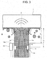
- FIG. 3 is a conceptual sectional elevational view illustrating a configuration including the collection distance adjuster.
- the collection distance adjuster 50 adjusts a position of the light collector 12 in an optical axis direction.
- the optical axis direction position of the light collector 12 can be adjusted by using the collection distance adjuster 50.
- the distance to be adjusted may be estimated from a previously measured shape of the workpiece 1 and position of the light collector 12.
- the distance between the light collector 12 and the workpiece 1 may be adjusted according to need to an optimum distance by feeding back the measured value of the propagation distance D p or the collection distance D f .
- FIG. 4 is a conceptual sectional elevational view illustrating a configuration including the movable driver.
- the movable driver 90 includes a restraining part 91, an arm 92, a joint 93, and a power part 95.
- the power part 95 is externally fixed and supported.
- the joint 93 can be changed in angle by the power unit 95. Accordingly, a direction of the arm 92 is changed to move the light collector 12 and the sound sensor 10 attached to the water nozzle 5 connected to the movable driver 90 by the restraining part 91. As a result, an interval between the workpiece 1 and those of the water nozzle 5, the sound sensor 10 and the light collector 12 is changed.
- the movable driver 90 moves the water nozzle 5, the light collector 12 and the sound sensor 10 which are attached to the water nozzle 5 in accordance with the position of the processing point 2 to be sequentially moved on the processing surface of the workpiece 1.
- FIG. 5 is a conceptual sectional elevational view illustrating a configuration of a modification of the movable driver.
- the power part 95 of the movable driver 90 is fixed to the workpiece 1.
- the movable driver 90 changes the interval between the water nozzle 5 and the sound sensor 10, and the workpiece 1.
- the movable driver 90 changes the position of the water nozzle 5 and the sound sensor 10, corresponding to the movement of the processing point 2.
- the interval between the water nozzle 5 and the sound sensor 10, and the workpiece 1 may be manually adjusted using the movable driver 90.
- the laser light 11a irradiated onto the processing point 2 of the workpiece 1 causes an ablation phenomenon, i.e., a phenomenon in which a constituent substance of the surface of the workpiece 1 is explosively released when plasma is generated.
- an ablation phenomenon i.e., a phenomenon in which a constituent substance of the surface of the workpiece 1 is explosively released when plasma is generated.
- a shock wave is generated in the processing point 2 as a sound source.
- the shock wave acts on the processing point 2 to impart a compression stress to the processing point 2.
- the generated shock wave propagates in the liquid. Then, the shock wave is transmitted to the air from the liquid through a liquid-air interface, propagates in the air, and reaches the sound sensor 10. Then, the shock wave is received by the sound sensor 10.
- FIG. 6 is a waveform diagram illustrating a received waveform image of the sound sensor.
- a horizontal axis represents time, and a starting point of each oscillation period is set to 0.
- a vertical axis represents a voltage value captured by the sound sensor.
- Ti of FIG. 6 is a reference time point of the time width.
- FIGS. 7A and 7B are each a conceptual graph for explaining a setting of a reference point of time width calculation, in which FIG. 7A is undesirable example, and FIG. 7B is a desirable example.
- a horizontal axis represents the entire time flow
- a vertical axis represents a voltage value as in the case of FIG. 6 .
- dashed lines each represent a start time point of transmission.
- a solid line Ti represents a reference time point.
- FIG. 7A a relationship between the time point represented by the dashed line and Ti represented by the continuous line is not fixed.
- FIG. 7B the relationship between the time point represented by the dashed line and Ti represented by the solid line is fixed. It is desirable that the reference time point Ti is a signal that satisfies such a condition.
- At least one Ti time point exists in 100 ms which is one period. Assuming that laser oscillation time is 0 ms, it is desirable that Ti is a fixed value equal to or larger than 0 ms and less than 100 ms.
- a signal source for obtaining the Ti signal a setting signal estimated from a Q switch time point from the laser light source 11 or a pulse repetition frequency of the laser light 11a can be used.
- Te of FIG. 6 is an arrival time of the shock wave.
- the arrival time can be determined using a threshold determination that adopts a time at which a signal intensity exceeds a certain threshold, a peak determination that adopts a peak time of a certain waveform, a zero-cross method that adopts a time at which the signal intensity crosses a zero point, or a method that takes correspondence between the shock wave and a reference wave.
- the peak determination is used to obtain the shock wave arrival time.
- the time width Tw is a time width obtained by subtracting time Ti from time Te. For example, assuming that Ti is made to coincide with a laser emission time point, obtained Tw almost represents a time length from when the laser light acts on the processing point to when the shock wave reaches the sound sensor 10, i.e., a propagation time of the shock wave. A time point, at which a command signal is transmitted to the laser light source 11, can be used as the laser light emission time point.
- FIG. 8 is a conceptual graph for explaining calculation of the shock wave propagation time.
- FIG. 9 is a conceptual view for explaining calculation of the shock wave propagation time. The following is the case in which Ti is the laser light emission time point.
- the time width Tw is a sum of a time T L during which the shock wave propagates in the liquid and a time T G during which the shock wave goes out of the liquid and propagates in the air. It is empirically considered that a signal that the sound sensor 10 significantly detects as the shock wave is principally a signal emitted from the processing point 2, passing through the liquid via the shortest way, and propagating in the air. That is, in FIG. 9 , the shock wave emitted from the processing point 2, i.e., a sound wave caused by the shock propagates by a distance of a diameter R of a water column, then propagates by a distance L in the air, and reaches the sound sensor 10. This appears as the propagation time of FIG. 9 .
- Tg T W ⁇ T L
- V G is a propagation speed of the sound wave in the air.
- a relative positional relationship of the sound sensor 10 to the water nozzle 5 and the light collector 12 is known, so that when the propagation distance D p is known as described above, a collection distance D f between the processing point 2 and the light collector 12 or processing distance D 0 between the processing point 2 and a representative point of the laser processing apparatus 100 can be calculated.
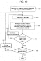
- FIG. 10 is a block diagram illustrating a procedure of a laser processing method according to the first embodiment.
- the propagation distance D p is assumed to be a reference distance.
- the reference distance may be the collection distance D f or the processing distance D 0 in place of the propagation distance D p .
- a reference time width with respect to the reference distance is detected and acquired (step S01).
- the laser light 11a is irradiated onto the processing point 2 which is an irradiation target point of the workpiece 1 (step S02).
- a propagation time of the shock wave generated upon each laser light irradiation is acquired, and the propagation distance D p is calculated (step S03).
- the collection distance D f and the processing distance D 0 of a determination target are calculated from the propagation distance D p .
- step S04 It is determined whether or not the collection distance D f falls within a proper range (step S04). When it is determined that the collection distance D f does not fall within a proper range (NO in step S04), the collection distance adjuster 50 is used to correct the collection distance D f (step S05), and step S02 and subsequent steps are repeated. When it is determined that the collection distance D f falls within a proper range (YES in step S04), processing for the processing point 2 as the irradiation target is determined to have been completed. Subsequently, it is determined whether or not all the processing target points set in the workpiece 1 have been subjected to processing (step S06). When it is determined that all of the processing target points set in the workpiece 1 have been subjected to processing (YES in step S06), the laser processing is determined to have ended.
- step S06 When it is determined that all the processing target points set in the workpiece 1 have not been subjected to processing (NO in step S06), any one of the processing target points in the workpiece 1 that are determined not to have been subjected to processing is set to the irradiation target, that is, the processing point 2 is moved to a point that has not been subjected to processing (step S07). Then, step S02 and subsequent steps are repeated.
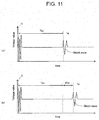
- FIGS. 11A and 11B are waveform diagrams each illustrating a received waveform image of the sound sensor when the distance from the processing point of the workpiece has changed, in which FIG. 11A illustrates a signal before the change, and FIG. 11B illustrates a signal after the change.
- FIG. 11A illustrates a signal before the change
- FIG. 11B illustrates a signal after the change.
- assumed is a case where a distance between the laser processing apparatus 100 and processing point 2 of the workpiece 1, that is, the processing distance D 0 is increased in association with movement of the processing.
- the arrival time of the shock wave to the sound sensor 10 is delayed by dTw as compared to a reference time width Twi in the case of FIG. 11A as a reference, that is, the propagation time is increased by dTw.
- the radius R of the water column is hardly changed even when the processing distance is changed, so that the increase dTw of the propagation time can be regarded substantially as a pure time change caused by a change in the air distance.
- a value obtained by multiplying dTw by a propagation speed V G of the sound wave in the air is an increase dD of the propagation distance
- the propagation distance D p is calculated by adding the increase dD to a reference distance D p0 to get (D p0 + dD).
- a variation in the radius R of the water column can be controlled to be smaller than the propagation distance D p and the collection distance D f to be calculated and a measurement resolution of the processing distance D 0 .
- the variation is reduced by suppressing pulsation in the water stream source 21 or suppressing occurrence of a swirling flow in a path to the water nozzle 5.
- a distance between the processing point and a reference position can be stably measured.
- FIG. 12 is a conceptual sectional elevational view illustrating a configuration of a laser processing apparatus according to a second embodiment.
- the present embodiment is a modification of the first embodiment.
- the laser processing apparatus 100 according to the present embodiment includes a light detector 13.
- the light detector 13 is used to detect an actual light emission time point, and a time point of a signal corresponding to the light emission time point is set to Ti, whereby measurement accuracy of the propagation distance D p and thus the collection distance D f can be enhanced.
- FIG. 13 is a conceptual sectional elevational view illustrating a configuration of a laser processing apparatus according to a third embodiment.
- the present embodiment is a modification of the first embodiment.
- the laser processing apparatus 100 according to the present embodiment includes two sound sensors 15a and 15b. The number of the sound sensors may be three or more.
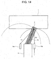
- FIG. 14 is a conceptual sectional elevational view for explaining measurement of the processing distance.
- the shock wave is emitted from the processing point 2 and reaches the two sound sensors 15a and 15b.
- a distance between the processing point 2 and a reception part of the sound sensor 15a calculated from the propagation time to the sound sensor 15a is denoted as D1. From this, it is estimated that the processing point 2 exists on a sphere having a radius D1 from the reception part of the sound sensor 15a.
- D2 a distance between the processing point 2 and a reception part of the sound sensor 15b calculated from the propagation time to the sound sensor 15b. From this, it is estimated that the processing point 2 exists on a sphere having a radius D2 from the reception part of the sound sensor 15b.
- the processing point 2 exists on an intersecting line of the sphere having the radius D1 from the reception part of the sound sensor 15a and the sphere having the radius D2 from the reception part of the sound sensor 15b.
- the points on the intersecting line innumerably exist; however, a point at which the intersecting line contacts the surface of the workpiece 1 can be estimated as the processing point 2.
- a point on the intersecting line closest to the surface of the workpiece 1 can be estimated as the processing point 2.
- an intermediate point between two points of the intersecting line penetrating the workpiece 1 can be estimated as the processing point 2.
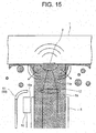
- FIG. 15 is a conceptual sectional elevational view illustrating a configuration of a laser processing apparatus according to a fourth embodiment.
- the present embodiment is a modification of the first embodiment.
- the laser processing apparatus 100 according to the present embodiment includes a water splash adhesion prevention part 60 for preventing water splashing back at the workpiece 1 from falling on the sound detector 10a of the sound sensor 10.
- the water splash adhesion prevention part 60 can be realized by using a protection cover 61 as illustrated in FIG. 15 .
- the protection cover 61 is formed in such a direction as to prevent coming water from falling on the sound detector 10a of the sound sensor 10.
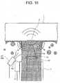
- FIG. 16 is a conceptual sectional elevational view illustrating a configuration of a modification of the laser processing apparatus according to the fourth embodiment.
- the laser processing apparatus 100 includes an air blower 62 as the water splash adhesion prevention part 60.
- the air blower 62 faces a side from which the water splash comes to the sound sensor 10 and blows off the water splash to thereby prevent the water from falling on the sound detector 10a of the sound sensor 10.
- the present embodiment is a modification of the first embodiment.
- the sound sensor 10 according to this fifth embodiment includes a water influence relieving part 70.
- the water influence relieving part 70 is provided for preventing a change in the sensitivity of the sound sensor 10 due to falling of the water splash caused when the water stream 5a collides with the workpiece 1.
- the following describes specific examples of the water influence relieving part 70.
- the examples include a case where the surface of the sound detector is treated and a case where a special geometric shape is added to the sound detector.
- the above two cases may be combined to realize the water influence relieving part 70.
- FIGS. 17A and 17B are conceptual views each illustrating a configuration in a case where the sound sensor 10 includes a sound detector 10b that has been subjected to surface treatment that makes wettability of a surface of the sound detector 10b lower, in which FIG. 17A is a plan view, and FIG. 17B is a front view.
- Examples of the surface treatment that makes wettability of the surface of the sound detector 10b lower include a method of coating a high hydrophobicity material such as oil onto the surface and a method of forming a highly hydrophobic pattern such as pattern having fine convex parts like a lotus leaf on the surface. This prevents the surface of the sound detector 10b from being covered with water 5b of the water splash, so that the problems such as a sensitivity change do not occur.
- FIGS. 18A and 18B are conceptual views each illustrating a configuration in a case where the sound sensor 10 includes a sound detector 10c that has been subjected to surface treatment that makes wettability of an outer surface of the sound detector 10c higher, in which FIG. 18A is a plan view, and FIG. 18B is a front view.
- Examples of the surface treatment that makes wettability of the outer surface of the sound detector 10b higher include: a method of coating a high hydrophilicity material such as titanium oxide onto the surface; a method of forming a highly hydrophilic pattern; or a method of alternately forming a highly hydrophilic pattern and a highly hydrophobic pattern on the surface.
- FIGS. 19A and 19B are conceptual view each illustrating a configuration in a case where the sound sensor 10 includes a sound detector 10d on an outer surface on which a convex geometric shape is formed, in which FIG. 19A is a plan view, and FIG. 19B is a front view.
- FIG. 19A is a plan view
- FIG. 19B is a front view.
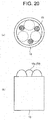
- FIGS. 20A and 20B are conceptual view each illustrating a configuration in a case where the sound sensor 10 includes a sound detector 10e on an outer surface on which a geometric shape including convex portions is formed, in which FIG. 20A is a plan view, and FIG. 20B is a front view.
- FIG. 20A is a plan view
- FIG. 20B is a front view.
- FIGS. 21A and 21B are conceptual view each illustrating a configuration in a case where the sound sensor 10 includes a sound detector 10f on an outer surface on which a concave geometric shape is formed, in which FIG. 21A is a plan view, and FIG. 21B is a front view.
- the water 5b is stably stored on the surface of the sound detector 10f. This prevents the sensitivity change.
- FIGS. 22A and 22B are conceptual view each illustrating a configuration in a case where the sound sensor 10 includes a sound detector 10g on an outer surface on which a geometric shape including concave portions is formed, in which FIG. 22A is a plan view, and FIG. 22B is a front view.
- the water 5b is stably stored on the surface of the sound detector 10f. This prevents the sensitivity change.
- FIG. 23 is a conceptual sectional elevational view illustrating a configuration of a laser processing apparatus according to a sixth embodiment.
- the present embodiment is a modification of the first embodiment.
- the sound sensor 10 of the laser processing apparatus according to the present embodiment has an external environment influence relieving part 80. Examples of the external influence on the sound sensor 10 include mechanical vibration, sound noise, and electric noise.
- the external environment influence relieving part 80 includes a mechanical vibration suppressing part 80a, a sound noise reducing part 80b ( FIG. 24 ), and an electric noise reducing part 80c.
- the mechanical vibration suppressing part 80a is provided between the sound sensor 10 and the water nozzle 5 to which the sound sensor 10 is attached.
- the mechanical vibration suppressing part 80a is formed from a damper material such as rubber or a spring.
- the electric noise reducing part 80c is a part that applies shielding to a cable for transmitting a signal received by the sound sensor 10.
- the reduction or suppression of the electric noise can be achieved also by power supply stabilizing measures that have a device using a stabilized power source.
- FIG. 24 is a vertical cross-sectional view illustrating a configuration of the sound sensor.
- the sound sensor 10 has a front plate 8b and a piezoelectric vibrator 8d serving as the sound detector 10a, electrodes 8c and 8f sandwiching the piezoelectric vibrator 8d from front and rear sides, and a casing 8a that supports the front plate 8b and houses therein the piezoelectric vibrator 8d and the electrodes 8c and 8f.
- the sound sensor 10 includes the sound noise reducing part 80b between the piezoelectric vibrator 8d, the electrodes 8c and 8f and the casing 8a.
- the sound noise reducing part 80b may be provided outside the sound sensor 10, serving also as the mechanical vibration suppressing part 80a.
- a frequency band other than a desired frequency can be cut off to narrow the frequency band of the sound sensor.
- filtering by applying filtering to a sound signal at a signal circuit from the sound sensor 10 or at the calculator 30, noise unrelated to the shock wave can be reduced.
- the filtering include a band-pass filter, a high-pass filter, a low-pass filter, a band elimination filter, an addition average filter, and a moving average filter, and imaging such as aperture synthesis using signals obtained through multipoint measurement may be performed.
- FIG. 25 is a graph for explaining an effect of the laser processing apparatus according to the present embodiment.
- a horizontal axis represents a sound frequency and a vertical axis represents a sound intensity.
- a shock wave denoted by a continuous line is captured by the sound sensor 10 as a signal, which includes sound noise denoted by a broken line.
- a frequency band A in FIG. 25 is a center frequency band of the noise, in which most of the received signal is the noise.
- a frequency band B is a frequency band close to a center frequency band of the shock wave and a frequency band in which the noise intensity is low.
- the shock wave itself has wide band characteristics, thus allowing such narrowing to be achieved.
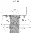
- FIG. 26 is a conceptual sectional elevational view illustrating a configuration of a laser processing apparatus according to a seventh embodiment.
- the present embodiment is a modification of the first embodiment.
- a distance from a leading end of the water nozzle 5 to the sound detector 10a is assumed to be Ds.
- the sound sensor 10 is installed on an inner wall surface of the water nozzle 5.
- the sensor surface of the sound detector 10a faces toward the water stream in the water nozzle 5, and specifically with this embodiment, the sensor surface of the sound detector 5 faces the inner wall surface.
- an installation structure of the sound sensor 10 is not limited to this. For example, installation structures as illustrated in FIGS. 27 or 28 may be possible.
- FIG. 27 is a sectional elevational view for explaining a first modification of the installation structure of the sound sensor.
- the sound sensor 10 is installed such that the sensor surface thereof faces in a water flow direction.
- FIG. 28 is a sectional elevational view for explaining a second modification of the installation structure of the sound sensor.
- the sound sensor 10 is provided at a portion obtained by cutting off a part of the inner wall surface of the water nozzle 5 so as to ensure a waveguide.
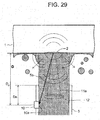
- FIG. 29 is a vertical cross-sectional view for explaining a first sound transmission path.
- FIG. 30 is a vertical cross-sectional view for explaining a second sound transmission path.
- the sound propagation path to the sound sensor 10 may completely submerge in water as illustrated in FIG. 29 .
- the sound propagation path may be formed such that the sound propagates in water until it reaches the water nozzle 5, then propagates on the inner wall surface of the water nozzle 5 as a surface wave, and eventually reaches the sound sensor 10.
- D 0 D p ⁇ Ds
- Ts Ds / Vs
- Vs is a sound velocity of the surface wave and Ds is also known.
- the processing distance D 0 can be calculated also in the present embodiment.
- FIG. 31 is a waveform diagram illustrating a received waveform image of the sound sensor of the laser processing apparatus according to the seventh embodiment.
- a horizontal axis represents time, and a starting point of each oscillation period is set to 0.
- a vertical axis represents a voltage value captured by the sound sensor as a received waveform. After transmission, a first shock wave arrives, followed by a second shock wave.
- the first shock wave corresponds to a shock wave that propagates as a surface wave in the middle of the propagation
- the second shock wave corresponds to a shock wave that propagates completely in water.
- a sound propagation speed of the surface wave is higher than that in water, so that the first shock wave arrives first.
- the processing distance D 0 can be calculated by using one of the first and second shock waves.
- an average of the first and second shock waves may be adopted.
- the sound sensor 10 has directivity. Thus, as a method for detecting the sound propagating in water or on the surface of the water nozzle 5 with high sensitivity, a shape of the sound sensor 10 may be adjusted. However, it is not realistic to adjust the shape of the sound sensor 10 every time when an installation position or posture of the sound sensor 10 is changed. Thus, a sound shoe is interposed between the sound sensor 10 and the water nozzle 5 so as to adjust propagation performance of the sound to the sound sensor 10.
- a material for the sound shoe is desirably one with excellent machinability. Further, in terms of sound propagation, the material desirably has a sound velocity close to that of water and a density lower than that of metal. For example, acrylic may be suitably used.
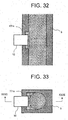
- FIGS. 32 to 43 each illustrate an installation structure of the sound shoe.
- FIG. 32 is a vertical cross-sectional view illustrating an installation structure taken along and viewed from a line XXXII-XXXII of FIG. 33 in a case where a sound shoe 101a is formed into a columnar shape having a horizontally extending axis.
- FIG. 33 is a cross-sectional plan view.
- the sound shoe 101a has a shape obtained by removing a portion corresponding to a cross-part of a flow path of the water nozzle 5.
- the sensor surface of the sound detector 10a of the sound sensor 10 also faces toward the water stream in the water nozzle 5.
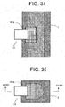
- FIG. 34 is a vertical cross-sectional view illustrating an installation structure taken along and viewed from a line XXXIV-XXXIV of FIG. 35 in a case where a sound shoe is formed into a flat-plate shape.
- FIG. 35 is a cross-sectional plan view.
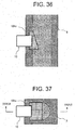
- FIG. 36 is a vertical cross-sectional view illustrating an installation structure taken along and viewed from a line XXXVI-XXXVI of FIG. 37 in a case where a sound shoe 101c is formed into a tapered shape.
- FIG. 37 is a cross-sectional plan view.
- FIG. 38 is a vertical cross-sectional view illustrating an installation structure taken along and viewed from a line XXXVIII-XXXVIII of FIG. 39 in a case where a sound shoe 101d is formed into a cone shape.
- FIG. 39 is a cross-sectional plan view.
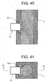
- FIG. 40 is a vertical cross-sectional view illustrating an installation structure taken along and viewed from a line XL-XL of FIG. 41 in a case where a sound shoe 101e is formed into a rotary semielliptical shape.
- FIG. 41 is a cross-sectional plan view.
- FIG. 42 is a vertical cross-sectional view illustrating an installation structure taken along and viewed from a line XLII-XLII of FIG. 43 in a case where the sound sensor 10 is disposed in an inclined manner.
- FIG. 43 is a cross-sectional plan view.
- FIG. 44 is a conceptual vertical cross-sectional view illustrating a configuration of a laser processing apparatus according to an eighth embodiment.
- FIG. 45 is a conceptual vertical cross-sectional view illustrating a configuration of a modification of a laser processing apparatus according to an eighth embodiment.
- Those embodiments are modifications of the first embodiment.
- water supply to the water nozzle 5 is provided by water flow in one pipe or more pipes meeting from different directions.
- water flow comes from two pipes.
- Each pipe is a flexible pipe such as a hose 124. So, the light collector 12 and the water nozzle 5 shown in FIG. 44 and FIG. 45 are able to move in a unified manner.
- a cylindrical buffer layer 121 that receives the water stream and a cylindrical injection layer 122 having a diameter smaller than that of the buffer layer 121 are continuously connected through a tapered part 123.
- the laser light is transmitted through the cylindrical buffer layer 121 and the cylindrical irradiation layer 122.
- each hose 124 may be connected with each nozzle 5c provided in the water nozzle 5 and banded together by a band not shown.
- a mounting angle is about 60 degree to the direction of flow-out from the cylindrical irradiation layer 122, are shown in FIG. 44 and FIG. 45 , the mounting angle may be less or may be larger up to 90 degree.
- the number of the water supply routes is not limited to one, but may be two or more. Further, the water supply routes may be the same or different in terms of diameter and/or flow rate.
- a flow straightener 126 may be provided.
- the flow straightener 126 straightens the turbulent water stream.
- the flow straightener 126 suppresses scattering of water flow after coming up at the workpiece 1.
- the configuration of the flow straightener 126 will be described referring FIG. 45 .
- a disk-shaped air-water separating window 125, through which the razor light can penetrate, is provided at the end of upstream end of the buffer layer 121.
- the separating window 125 constitutes a part of a boundary between the inner water in the water nozzle 5 and the outer air.
- the light collector 12 is located out of the separating window 125, or in the outer air. The laser light passes through the light collector 12 and is then transmitted to the processing point 2 through the flow straightener 126.
- An O-ring is provided at inner side, or water side of the separating window 125.
- a pressing plate 125a having an opening formed at the center area.
- a water seal-tightness of the separating window 125 is secured by compressing the O-ring 125b with the pressing plate 125a.
- the sound sensor 10 may be installed outside the water nozzle 5 as illustrated in FIG. 44 and FIG. 45 .
- FIG. 46 is a conceptual perspective view illustrating a configuration of a flow straightener in a laser processing apparatus of the present embodiment.
- the flow straightener 126 includes a hollow cylindrical flow smoothing cylinder 126a and four flow smoothing plates 126b. Each flow smoothing plate 126b is attached at its side surface to the flow smoothing cylinder 126a. Each flow smoothing plate 126b extends along the axis of and spreads to radial direction of the flow smoothing cylinder 126a. Each flow smoothing plate 126b overhangs to upstream from the flow smoothing cylinder 126a.
- the inner diameter of the flow smoothing cylinder 126a is larger than the outer diameter of the laser light beam in order to make the laser light pass through the flow smoothing cylinder 126a.
- Each of two circles 121a and 121b shows a part of outer surface of the buffer layer 121.
- the position of the circle 121a is upper stream than the position of the circle 121b.
- a cylindrical plane containing the circles 121a and 121b, the flow smoothing cylinder 126a and the flow smoothing plates 126b divide the buffer layer 121 into a flow path in the flow smoothing cylinder 126a and four flow paths divided from the annular section by the four flow smoothing plates 126b.
- the number of the flow smoothing plates 126b is not limited to four, but may be three or more than four.
- flow smoothing plate 126b spreads radially and extends axially
- they may be inclined from the axial or/and radial direction of the flow smoothing plate 126b.
- flow smoothing wing may be provided along inner surface of the water nozzle 5.
- the light collector 12 and the water nozzle 5 shown in FIG. 44 are able to move in a unified manner, and the water nozzle 5 can supply the straightened water flow to the processing point 2.
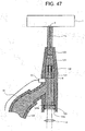
- FIG. 47 is a conceptual vertical cross-sectional view illustrating a configuration of another modification of the eighth embodiment.
- the sound sensor 10 may be installed inside the water nozzle 5 as illustrated in FIG. 47 .
- the sound sensor 10 may be installed upstream of the flow straightener 126, or sometimes preferably installed downstream of the buffer layer 121 so as to avoid influence of a turbulence.
Landscapes
- Physics & Mathematics (AREA)
- Engineering & Computer Science (AREA)
- Optics & Photonics (AREA)
- Mechanical Engineering (AREA)
- Plasma & Fusion (AREA)
- Chemical & Material Sciences (AREA)
- General Physics & Mathematics (AREA)
- Metallurgy (AREA)
- Materials Engineering (AREA)
- Organic Chemistry (AREA)
- Crystallography & Structural Chemistry (AREA)
- Thermal Sciences (AREA)
- General Engineering & Computer Science (AREA)
- High Energy & Nuclear Physics (AREA)
- Radar, Positioning & Navigation (AREA)
- Remote Sensing (AREA)
- Laser Beam Processing (AREA)
Abstract
Description
- The present embodiments relate to a laser processing apparatus, a laser processing method, and a distance measurement method.
- In a plant such as a nuclear power plant where high safety is required, equipment such as incore equipment which is difficult for human operators to access is accessed using automatic equipment for various maintenance works such as inspection, surface modification, and repair during periodical inspection. The maintenance works include a countermeasure against SCC (Stress Corrosion Cracking) caused by a tensile stress remaining in a welding part, and there is developed a laser peening method and apparatus capable of preventing occurrence of the SCC.
-
FIG. 48 is a conceptual view illustrating a principle of laser peening. Alaser light 11a having a pulse width of about several ns is collected on a spot having a diameter of about 1 mm by alight collector 12 to be irradiated onto aworkpiece 1. Then, a surface of theworkpiece 1 absorbs energy and is turned into a plasma. When a circumference of aplasma 4 is covered with aliquid 6 transparent with respect to a wavelength of the laser light, expansion of theplasma 4 is prevented. Then, an inner pressure of theplasma 4 reaches about several GPa to apply shock to theworkpiece 1. In this event, astrong shock wave 7 occurs in theworkpiece 1 and theliquid 6. The shock wave propagates in the workpiece to cause plastic deformation and to change a residual stress at aprocessing point 2 into a compressive residual stress. - The laser peening less depends on a material strength in a hardening process than another peening technique such as a shot peening, a water-jet peening, or an ultrasonic shot peening and is capable of processing the
workpiece 1 up to its inner part with a depth of about 1 mm from a surface of theworkpiece 1 in a plate thickness direction. Further, the laser peening provides excellent processability at a narrow portion because there is no reaction force during the processing and its processing apparatus can be easily downsized. For example, a laser processing apparatus and method that can be applied to a workpiece having a small tube inner diameter are disclosed. - Generally, in the laser peening, the
workpiece 1 needs to be installed in theliquid 6 or applied with coating in order to obtain a high plasma stress confinement effect. This restricts a laser peening execution environment and complicates processing procedures. However, a technique that allows the laser peening to be carried out in an air environment is now developed. In this technique, water is jetted to theworkpiece 1 with transmission of a laser, whereby local watertight condition along a light path and a processing point is achieved. This may significantly enlarge an application range of the laser peening. -
-
FIG. 1 is a block diagram illustrating a configuration of a laser processing apparatus according to a first embodiment. -
FIG. 2 is a conceptual sectional elevational view illustrating a configuration of around the water nozzle. -
FIG. 3 is a conceptual sectional elevational view illustrating a configuration including the collection distance adjuster. -
FIG. 4 is a conceptual sectional elevational view illustrating a configuration including the movable driver. -
FIG. 5 is a conceptual sectional elevational view illustrating a configuration of a modification of the movable driver. -
FIG. 6 is a waveform diagram illustrating a received waveform image of the sound sensor. -
FIGS. 7A and 7B are each a conceptual graph for explaining a setting of a reference point of time width calculation, in whichFIG. 7A is undesirable example, andFIG. 7B is a desirable example. -
FIG. 8 is a conceptual graph for explaining calculation of the shock wave propagation time. -
FIG. 9 is a conceptual view for explaining calculation of the shock wave propagation time. -
FIG. 10 is a block diagram illustrating a procedure of a laser processing method according to the first embodiment. -
FIGS. 11A and 11B are waveform diagrams each illustrating a received waveform image of the sound sensor when the distance from the processing point of the workpiece, in whichFIG. 11A illustrates a signal before the change, andFIG. 11B illustrates a signal after the change. -
FIG. 12 is a conceptual sectional elevational view illustrating a configuration of a laser processing apparatus according to a second embodiment. -
FIG. 13 is a conceptual sectional elevational view illustrating a configuration of a laser processing apparatus according to a third embodiment. -
FIG. 14 is a conceptual sectional elevational view for explaining measurement of the processing distance. -
FIG. 15 is a conceptual sectional elevational view illustrating a configuration of a laser processing apparatus according to a fourth embodiment. -
FIG. 16 is a conceptual sectional elevational view illustrating a configuration of a modification of the laser processing apparatus according to the fourth embodiment. -
FIGS. 17A and 17B are conceptual views each illustrating a configuration in a case where thesound sensor 10 includes asound detector 10b that has been subjected to surface treatment that makes wettability of a surface of thesound detector 10b lower, in whichFIG. 17A is a plan view, andFIG. 17B is a front view. -
FIGS. 18A and 18B are conceptual views each illustrating a configuration in a case where thesound sensor 10 includes asound detector 10c that has been subjected to surface treatment that makes wettability of an outer surface of thesound detector 10c higher, in whichFIG. 18A is a plan view, andFIG. 18B is a front view. -
FIGS. 19A and 19B are conceptual view each illustrating a configuration in a case where thesound sensor 10 includes asound detector 10d on an outer surface on which a convex geometric shape is formed, in whichFIG. 19A is a plan view, andFIG. 19B is a front view. -
FIGS. 20A and 20B are conceptual view each illustrating a configuration in a case where thesound sensor 10 includes asound detector 10e on an outer surface on which a geometric shape including convex portions is formed, in whichFIG. 20A is a plan view, andFIG. 20B is a front view. -
FIGS. 21A and 21B are conceptual view each illustrating a configuration in a case where thesound sensor 10 includes asound detector 10f on an outer surface on which a concave geometric shape is formed, in whichFIG. 21A is a plan view, andFIG. 21B is a front view. -
FIGS. 22A and 22B are conceptual view each illustrating a configuration in a case where thesound sensor 10 includes asound detector 10g on an outer surface on which a geometric shape including concave portions is formed, in whichFIG. 22A is a plan view, andFIG. 22B is a front view. -
FIG. 23 is a conceptual sectional elevational view illustrating a configuration of a laser processing apparatus according to a sixth embodiment. -
FIG. 24 is a vertical cross-sectional view illustrating a configuration of the sound sensor. -
FIG. 25 is a graph for explaining an effect of the laser processing apparatus according to the present embodiment. -
FIG. 26 is a conceptual sectional elevational view illustrating a configuration of a laser processing apparatus according to a seventh embodiment. -
FIG. 27 is a sectional elevational view for explaining a first modification of the installation structure of the sound sensor. -
FIG. 28 is a sectional elevational view for explaining a second modification of the installation structure of the sound sensor. -
FIG. 29 is a vertical cross-sectional view for explaining a first sound transmission path. -
FIG. 30 is a vertical cross-sectional view for explaining a second sound transmission path. -
FIG. 31 is a waveform diagram illustrating a received waveform image of the sound sensor of the laser processing apparatus according to the seventh embodiment. -
FIG. 32 is a vertical cross-sectional view illustrating an installation structure taken along and viewed from a line XXXII-XXXII ofFIG. 33 in a case where asound shoe 101a is formed into a columnar shape having a horizontally extending axis. -
FIG. 33 is a cross-sectional plan view. Thesound shoe 101a has a shape obtained by removing a portion corresponding to a cross-part of a flow path of thewater nozzle 5. -
FIG. 34 is a vertical cross-sectional view illustrating an installation structure taken along and viewed from a line XXXIV-XXXIV ofFIG. 35 in a case where a sound shoe is formed into a flat-plate shape. -
FIG. 35 is a cross-sectional plan view in a case where a sound shoe is formed into a flat-plate shape. -
FIG. 36 is a vertical cross-sectional view illustrating an installation structure taken along and viewed from a line XXXVI-XXXVI ofFIG. 37 in a case where asound shoe 101c is formed into a tapered shape. -
FIG. 37 is a cross-sectional plan view in a case where asound shoe 101c is formed into a tapered shape. -
FIG. 38 is a vertical cross-sectional view illustrating an installation structure taken along and viewed from a line XXXVIII-XXXVIII ofFIG. 39 in a case where asound shoe 101d is formed into a cone shape. -
FIG. 39 is a cross-sectional plan view in a case where asound shoe 101d is formed into a cone shape. -
FIG. 40 is a vertical cross-sectional view illustrating an installation structure taken along and viewed from a line XL-XL ofFIG. 41 in a case where asound shoe 101e is formed into a rotary semielliptical shape. -
FIG. 41 is a cross-sectional plan view in a case where asound shoe 101e is formed into a rotary semielliptical shape. -
FIG. 42 is a vertical cross-sectional view illustrating an installation structure taken along and viewed from a line XLII-XLII ofFIG. 43 in a case where thesound sensor 10 is disposed in an inclined manner. -
FIG. 43 is a cross-sectional plan view in a case where thesound sensor 10 is disposed in an inclined manner. -
FIG. 44 is a conceptual vertical cross-sectional view illustrating a configuration of a laser processing apparatus according to an eighth embodiment. -
FIG. 45 is a conceptual sectional elevational view illustrating a configuration of a modification of a laser processing apparatus according to an eighth embodiment. -
FIG. 46 is a conceptual perspective view illustrating a configuration of a flow straightener in a laser processing apparatus according to an eighth embodiment. -
FIG. 47 is a conceptual vertical cross-sectional view illustrating a configuration of another modification of the eighth embodiment. -
FIG. 48 is a conceptual view illustrating a principle of laser peening. - In order to obtain a sufficient stress improvement effect by the laser peening, it is necessary to consider the following point. That is, in order to generate a
shock wave 7 having required energy during irradiation of thelaser light 11a onto theworkpiece 1, it is necessary to control a spot diameter within a predetermined size so as to prevent the spot diameter from becoming too large. This is a matter common to cases where the laser peening is performed in an underwater environment, where the laser peening is performed with coating applied to theworkpiece 1, and where the laser peening is performed with a stream of jetting water. - The spot diameter of the
laser light 11a varies depending on a distance from thelight collector 12 provided in a laser irradiation head to theworkpiece 1. Thus, it is necessary to control the distance to a predetermined value. To this end, it is necessary to correctly measure a distance between a position onto which thelaser light 11a is irradiated, i.e., a surface of theworkpiece 1 and a reference position (a light collector, an optical head end face, or a nozzle leading end). - In this regard, for example, the following measurement technique is proposed. That is, the shock wave generated at a processing point is measured by means of a sound sensor to obtain a trigger from a laser light source as a start point and a time at which the shock wave reaches as an end point. Then, from a time width between the obtained start point and the end point, a distance between the processing point and the sound sensor is calculated.
- However, the above technique assumes that at least a space between the processing point and the sound sensor is filled continuously with liquid. In the laser peening using the water stream, the shock wave propagates in the liquid with the processing point existing in the liquid as a sound source, transmitted from the liquid to air through a liquid-air interface, propagates in the air, and reaches the sound sensor.
- A sound velocity in the liquid and that in the air differ significantly from each other. In addition, when the water stream is used for the laser peening, a thickness of a liquid film generated at the processing point varies, and the variation becomes a distance measurement error. Further, liquid splash caused by the water stream may be adhered to the sound sensor, which may cause the distance measurement error. In general measurement, an optical means such as a laser distance meter or a stereoscopic camera is used; however, an optical path is blocked or distorted by the water splash, making it substantially impossible to carry out the measurement. As described above, in the laser peening using the water stream, the distance between the processing point and the sound sensor cannot be measured by a simple shock wave time measurement or optical means.
- The object of embodiments of the present invention is therefore to allow stable measurement of the distance between the processing point and reference position even in the laser peening using, e.g., the water stream.
- According to an embodiment, there is provided a laser processing apparatus comprising: a laser light source for emitting a laser light; a light collector for collecting the laser light on a workpiece which is a target of surface hardening treatment; a water stream transmitter for supplying a water stream to a surface to be treated of the workpiece; a sound sensor for receiving a sound coming from the surface to be treated, the sound sensor being provided at a predetermined position relative to at least one of the water stream transmitter and the light collector; a time width acquisition part for acquiring a measurement time width from a reference time point to a time point when the sound sensor receives the sound; and
- a distance calculation part for calculating, based on the measurement time width, a distance from one of the water stream transmitter and the light collector to the surface to be processed.
- According to another embodiment, there is provided a laser processing method comprising: a reference measurement step of acquiring a reference measurement time width which is a time width from a time point of laser light irradiation by a laser light irradiation apparatus with a known reference distance to a time point of reception of a sound generated by the laser light irradiation; an irradiation step of performing the laser light irradiation by the laser light irradiation apparatus onto one of processing target points of a workpiece and acquiring a measurement time width which is a time width from a time point of the laser light irradiation to a time point of the reception of the sound generated by the laser light irradiation; and a distance calculation step of calculating a propagation distance between the laser light irradiation apparatus and the processing target based on the reference distance and a difference between the measurement time width acquired in the irradiation step and the reference measurement time width.
- According to another embodiment, there is provided a distance measurement method comprising: a reference measurement step in which a time width acquisition part acquires a reference measurement time width with respect to a known reference distance; an irradiation step in which the time width acquisition part acquires a measurement time width by laser light irradiation by a laser light irradiation apparatus; and a distance calculation step of calculating a propagation distance between the laser light irradiation apparatus and the processing target based on the reference distance and a difference between the measurement time width acquired in the irradiation step and the reference measurement time width.
- Hereinafter, with reference to the accompanying drawings, embodiments of a laser processing apparatus, a laser processing method and a distance measurement method of the present invention will be described. The same or similar portions are represented by the same reference symbols, and a duplicate description will be omitted.
-
FIG. 1 is a block diagram illustrating a configuration of a laser processing apparatus according to a first embodiment. A laser processing apparatus (a laser light irradiation apparatus) 100 irradiates a laser beam onto aworkpiece 1 in a gas atmosphere such as air atmosphere to apply surface hardening treatment. For the laser irradiation, one of processing target positions defined in theworkpiece 1 to be worked is selected as an irradiation target. The laser processing apparatus (the laser light irradiation apparatus) 100 includes alaser light source 11, awater stream source 21, a water nozzle 5 (a water stream transmitter), acalculator 30, acontroller 40, asound sensor 10, a collection distance adjuster 50 (FIG. 3 ), and a movable driver 90 (FIGS. 4 and5 ). Thewater nozzle 5 is attached with alight collector 12 for converging alaser light 11a to be irradiated onto theworkpiece 1. - The
laser light source 11 emits a laser light. The laser light may be, e.g., an Nd:YAG laser, a CO2 laser, an Er:YAG laser, a titanium sapphire laser, an alexandrite laser, a ruby laser, a fiber laser, a dye laser, and an excimer, but may be any laser light other than the above as long as it can impart required energy to the workpiece. Thelaser light source 11 may be a continuous wave type or a pulse wave type. Further, a laser light may be irradiated onto the same part of theworkpiece 1 from two or morelaser light sources 11. - The
light collector 12 collects the laser light onto theprocessing point 2 on a surface to be processed of theworkpiece 1. Thelight collector 12 may be a single convex lens, a combination of two or more convex lenses, or a combination of a convex lens and other lens. The convex lens may be a flat-convex lens, a convex-convex lens, or an aspheric lens. The lens that can be combined with the convex lens may be a flat-concave lens, a concave-concave lens, or a cylindrical lens. Alternatively, thelight collector 12 may be a concave mirror. - The laser light may be transmitted to the
light collector 12 by means of space transmission using a mirror or a lens, by means of fiber transmission using a fiber or a combination thereof. For profile uniformization of the laser light, a homogenizer or an aperture may be used. Further, for intensity adjustment, devices such as a λ/2 wavelength plate, a polarizer, a beam splitter, or a half mirror may be used. The optical system elements mentioned above may each be applied with coating that changes a reflectance or a transmittance in accordance with a laser wavelength. - The
water stream source 21 supplies water for forming a water stream to generate a partial liquid environment around the surface of theworkpiece 1 during irradiation of thelaser light 11a onto theworkpiece 1. Thewater stream source 21 may be of a type that supplies the water stream from a water pressure source through an on/off valve. Alternatively, thewater stream source 21 may be of a type that moves a piston to supply the water stream from a supply source. - The
water nozzle 5 has a tubular shape, and an upper stream side thereof is connected to thewater stream source 21 and an exit side thereof is open. Thewater nozzle 5 leads a water stream to theworkpiece 1 without bubble entrainment and jets liquid toward theworkpiece 1. Thelight collector 12 is attached to thewater nozzle 5 at a position spaced apart from the exit of thewater nozzle 5 by a predetermined distance or longer in the upstream direction so as not to be influenced by the water stream at the exit. - As the liquid to be used, one that does not catch fire in the air and does not prevent propagation of the laser light, for example, aqueous solution such as pure water, city water, or boric acid solution may be used. There are limited number of liquids that are transparent through all of wavelengths, so that it is necessary to consider compatibility between the liquid and the laser light, i.e., transmittance therebetween in selecting the above water solutions. A combination that can obtain a sufficient intensity after the laser light propagates a predetermined distance can be used even though an attenuation rate is high to some degree. By making the circumference of the water stream into an inert gas atmosphere, liquid that can catch fire in the air, for example, alcohols or oils can be used.
- Here, as a representative example, the air as the atmosphere and the city water as the liquid are assumed. Although the laser light and the water stream are coaxial in this example, they may have different axes as long as a water film can be partially obtained at the
processing point 2 of theworkpiece 1. Theprocessing point 2 is defined as a part of the surface of theworkpiece 1 to be processed by each irradiation of the laser light. - The
sound sensor 10 is fixed to, e.g., thewater nozzle 5 in order to get a certain positional relationship with thewater nozzle 5 and is configured to be able to detect the shock wave generated at theprocessing point 2 of theworkpiece 1 as a sound wave (sound). Thesound sensor 10 is fixed to thewater nozzle 5 such that a part that receives and detects the sound wave, i.e., asound detector 10a of thesound sensor 10 faces theworkpiece 1 side. An output of thesound sensor 10 is input to thecalculator 30. - The
sound sensor 10 is a probe for aerial ultrasonic wave measurement that uses a general piezoelectric element. Any sensors that can receive a frequency band of the shock wave to be measured, such as a water-proof speaker or a vibration meter that irradiates a laser onto surface of a diaphragm, may be used as thesound sensor 10. When the position relative to thewater nozzle 5 can be set to a predetermined position, thesound sensor 10 can be fixed to a member other than thewater nozzle 5. - The
calculator 30 includes a timer 31 (a time width acquisition part) and a distance calculator 32 (a distance calculation part). - The
timer 31 detects and acquires a time width Tw from a certain reference time Ti to a time Te at which the shock wave generated at theprocessing point 2 of the workpiece reaches thesound sensor 10. Thetimer 31 has a means for converting an analog signal detected from thesound sensor 10 into a digital signal. Thetimer 31 may be a measurement instrument called oscilloscope, a personal computer incorporating an AD converter, a personal computer connected to a dedicated device similar to the AD converter, or a combination of thereof. Thetimer 31 is connected to thelaser light source 11 that oscillates thelaser light 11a, or thewater stream source 21 that generates a water pressure required for formation of the water stream, and exchanges signals therewith. - The
distance calculator 32 calculates a distance between theprocessing point 2 and thesound sensor 10 based on a propagation time measured by thetimer 31. Here, a distance between a representative part of the laser processing apparatus (the laser light irradiation apparatus) 100, for example, the distance between a leading end of thewater nozzle 5 andtarget processing point 2 is referred to as a processing distance and is represented as a processing distance D0. Further, a distance between theprocessing point 2 and asound detector 10a of thesound sensor 10 is referred to as a propagation distance and represented as a propagation distance Dp. Further, a distance between thelight collector 12 and theprocessing point 2 is referred to as a collection distance and represented as a collection distance Df. A distance (processing distance D0) between thelaser processing apparatus 100 as a laser light irradiation apparatus and theprocessing point 2 can be obtained by measuring or calculating the propagation distance Dp or the collection distance Df. - The
controller 40 exchanges signals with thelaser light source 11, thewater stream source 21, thewater nozzle 5, thecalculator 30, thecollection distance adjuster 50, and themovable driver 90 and provides coordination among them. Nevertheless, thelaser light source 11, thewater stream source 21, thecalculator 30, thecollection distance adjuster 50, and themovable driver 90 can respectively adjust the set point of the output or ON and OFF by itself. -
FIG. 2 is a conceptual sectional elevational view illustrating a configuration of around the water nozzle. Theworkpiece 1 is disposed vertically above thewater nozzle 5, and awater stream 5a is jetted upward in the vertical direction. Although theworkpiece 1 is disposed vertically above thewater nozzle 5, the embodiment is not limited to this. That is, theworkpiece 1 may be disposed in the lateral direction of or vertically below thewater nozzle 5. - In the
water stream 5a directed toward theworkpiece 1 from thewater nozzle 5, thelaser light 11a is directed in the same direction. Thelaser light 11a is collected toward theworkpiece 1 by thelight collector 12 provided in thewater nozzle 5. In order to make an irradiation density of thelaser light 11a at theprocessing point 2 equal to or larger than a predetermined value, the collection distance Df between the position of thelight collector 12 and theprocessing point 2 is required to satisfy the following condition: F - ΔF < Df < F + ΔF. That is, it is necessary to make the collection distance Df falls within a predetermined range. In the above conditional expression, F is a focal length, and ΔF is a predetermined width. For appropriate positioning of thelight collector 12, the collection distance Df can be adjusted by thecollection distance adjuster 50 to be described later. - Therefore, the collection distance Df itself or a distance based on which the collection distance Df can be calculated needs to be measured. The
sound sensor 10 detects the shock wave generated when thelaser light 11a reaches theprocessing point 2. -
FIG. 3 is a conceptual sectional elevational view illustrating a configuration including the collection distance adjuster. Thecollection distance adjuster 50 adjusts a position of thelight collector 12 in an optical axis direction. In order to maintain the distance between thelight collector 12 and theworkpiece 1 in an appropriate range, the optical axis direction position of thelight collector 12 can be adjusted by using thecollection distance adjuster 50. At this time, the distance to be adjusted may be estimated from a previously measured shape of theworkpiece 1 and position of thelight collector 12. Alternatively, the distance between thelight collector 12 and theworkpiece 1 may be adjusted according to need to an optimum distance by feeding back the measured value of the propagation distance Dp or the collection distance Df. -
FIG. 4 is a conceptual sectional elevational view illustrating a configuration including the movable driver. Themovable driver 90 includes a restrainingpart 91, anarm 92, a joint 93, and apower part 95. Thepower part 95 is externally fixed and supported. The joint 93 can be changed in angle by thepower unit 95. Accordingly, a direction of thearm 92 is changed to move thelight collector 12 and thesound sensor 10 attached to thewater nozzle 5 connected to themovable driver 90 by the restrainingpart 91. As a result, an interval between theworkpiece 1 and those of thewater nozzle 5, thesound sensor 10 and thelight collector 12 is changed. - Further, the
movable driver 90 moves thewater nozzle 5, thelight collector 12 and thesound sensor 10 which are attached to thewater nozzle 5 in accordance with the position of theprocessing point 2 to be sequentially moved on the processing surface of theworkpiece 1. -
FIG. 5 is a conceptual sectional elevational view illustrating a configuration of a modification of the movable driver. In this modification, thepower part 95 of themovable driver 90 is fixed to theworkpiece 1. Also in the present modification, themovable driver 90 changes the interval between thewater nozzle 5 and thesound sensor 10, and theworkpiece 1. And themovable driver 90 changes the position of thewater nozzle 5 and thesound sensor 10, corresponding to the movement of theprocessing point 2. In terms of the motive power, the interval between thewater nozzle 5 and thesound sensor 10, and theworkpiece 1 may be manually adjusted using themovable driver 90. - The following describes operations of the thus configured
laser processing apparatus 100 according to the present embodiment. - The
laser light 11a irradiated onto theprocessing point 2 of theworkpiece 1 causes an ablation phenomenon, i.e., a phenomenon in which a constituent substance of the surface of theworkpiece 1 is explosively released when plasma is generated. As a result, a shock wave is generated in theprocessing point 2 as a sound source. The shock wave acts on theprocessing point 2 to impart a compression stress to theprocessing point 2. - First, the generated shock wave propagates in the liquid. Then, the shock wave is transmitted to the air from the liquid through a liquid-air interface, propagates in the air, and reaches the
sound sensor 10. Then, the shock wave is received by thesound sensor 10. -
FIG. 6 is a waveform diagram illustrating a received waveform image of the sound sensor. InFIG. 6 , a horizontal axis represents time, and a starting point of each oscillation period is set to 0. A vertical axis represents a voltage value captured by the sound sensor. Ti ofFIG. 6 is a reference time point of the time width. -
FIGS. 7A and 7B are each a conceptual graph for explaining a setting of a reference point of time width calculation, in whichFIG. 7A is undesirable example, andFIG. 7B is a desirable example. InFIGS. 7A and 7B , a horizontal axis represents the entire time flow, and a vertical axis represents a voltage value as in the case ofFIG. 6 . Further, dashed lines each represent a start time point of transmission. A solid line Ti represents a reference time point. InFIG. 7A , a relationship between the time point represented by the dashed line and Ti represented by the continuous line is not fixed. On the other hand, inFIG. 7B , the relationship between the time point represented by the dashed line and Ti represented by the solid line is fixed. It is desirable that the reference time point Ti is a signal that satisfies such a condition. - For example, in the case of a 10 Hz laser, at least one Ti time point exists in 100 ms which is one period. Assuming that laser oscillation time is 0 ms, it is desirable that Ti is a fixed value equal to or larger than 0 ms and less than 100 ms. As a signal source for obtaining the Ti signal, a setting signal estimated from a Q switch time point from the
laser light source 11 or a pulse repetition frequency of thelaser light 11a can be used. - Te of
FIG. 6 is an arrival time of the shock wave. The arrival time can be determined using a threshold determination that adopts a time at which a signal intensity exceeds a certain threshold, a peak determination that adopts a peak time of a certain waveform, a zero-cross method that adopts a time at which the signal intensity crosses a zero point, or a method that takes correspondence between the shock wave and a reference wave. In the example ofFIG. 6 , the peak determination is used to obtain the shock wave arrival time. - The time width Tw is a time width obtained by subtracting time Ti from time Te. For example, assuming that Ti is made to coincide with a laser emission time point, obtained Tw almost represents a time length from when the laser light acts on the processing point to when the shock wave reaches the
sound sensor 10, i.e., a propagation time of the shock wave. A time point, at which a command signal is transmitted to thelaser light source 11, can be used as the laser light emission time point. -
FIG. 8 is a conceptual graph for explaining calculation of the shock wave propagation time.FIG. 9 is a conceptual view for explaining calculation of the shock wave propagation time. The following is the case in which Ti is the laser light emission time point. - As illustrated in
FIG. 8 , the time width Tw is a sum of a time TL during which the shock wave propagates in the liquid and a time TG during which the shock wave goes out of the liquid and propagates in the air. It is empirically considered that a signal that thesound sensor 10 significantly detects as the shock wave is principally a signal emitted from theprocessing point 2, passing through the liquid via the shortest way, and propagating in the air. That is, inFIG. 9 , the shock wave emitted from theprocessing point 2, i.e., a sound wave caused by the shock propagates by a distance of a diameter R of a water column, then propagates by a distance L in the air, and reaches thesound sensor 10. This appears as the propagation time ofFIG. 9 . - Thus, the propagation time TL in the liquid is given by the following equation (1):

- As a result, Tg is calculated by the following equation (2), and a propagation distance Dp is calculated by the following equation (3):


- A relative positional relationship of the
sound sensor 10 to thewater nozzle 5 and thelight collector 12 is known, so that when the propagation distance Dp is known as described above, a collection distance Df between theprocessing point 2 and thelight collector 12 or processing distance D0 between theprocessing point 2 and a representative point of thelaser processing apparatus 100 can be calculated. -
FIG. 10 is a block diagram illustrating a procedure of a laser processing method according to the first embodiment. - When the positional relationship between the
processing point 2 and thelaser processing apparatus 100 is known, the propagation distance Dp is assumed to be a reference distance. The reference distance may be the collection distance Df or the processing distance D0 in place of the propagation distance Dp. First, a reference time width with respect to the reference distance is detected and acquired (step S01). Then, thelaser light 11a is irradiated onto theprocessing point 2 which is an irradiation target point of the workpiece 1 (step S02). A propagation time of the shock wave generated upon each laser light irradiation is acquired, and the propagation distance Dp is calculated (step S03). - Then, the collection distance Df and the processing distance D0 of a determination target are calculated from the propagation distance Dp.
- It is determined whether or not the collection distance Df falls within a proper range (step S04). When it is determined that the collection distance Df does not fall within a proper range (NO in step S04), the
collection distance adjuster 50 is used to correct the collection distance Df (step S05), and step S02 and subsequent steps are repeated. When it is determined that the collection distance Df falls within a proper range (YES in step S04), processing for theprocessing point 2 as the irradiation target is determined to have been completed. Subsequently, it is determined whether or not all the processing target points set in theworkpiece 1 have been subjected to processing (step S06). When it is determined that all of the processing target points set in theworkpiece 1 have been subjected to processing (YES in step S06), the laser processing is determined to have ended. - When it is determined that all the processing target points set in the
workpiece 1 have not been subjected to processing (NO in step S06), any one of the processing target points in theworkpiece 1 that are determined not to have been subjected to processing is set to the irradiation target, that is, theprocessing point 2 is moved to a point that has not been subjected to processing (step S07). Then, step S02 and subsequent steps are repeated. -
FIGS. 11A and 11B are waveform diagrams each illustrating a received waveform image of the sound sensor when the distance from the processing point of the workpiece has changed, in whichFIG. 11A illustrates a signal before the change, andFIG. 11B illustrates a signal after the change. For example, assumed is a case where a distance between thelaser processing apparatus 100 andprocessing point 2 of theworkpiece 1, that is, the processing distance D0 is increased in association with movement of the processing. - In this case, it is assumed that the arrival time of the shock wave to the
sound sensor 10 is delayed by dTw as compared to a reference time width Twi in the case ofFIG. 11A as a reference, that is, the propagation time is increased by dTw. The radius R of the water column is hardly changed even when the processing distance is changed, so that the increase dTw of the propagation time can be regarded substantially as a pure time change caused by a change in the air distance. Thus, a value obtained by multiplying dTw by a propagation speed VG of the sound wave in the air is an increase dD of the propagation distance, and the propagation distance Dp is calculated by adding the increase dD to a reference distance Dp0 to get (Dp0 + dD). - It is desirable that a variation in the radius R of the water column can be controlled to be smaller than the propagation distance Dp and the collection distance Df to be calculated and a measurement resolution of the processing distance D0. Specifically, the variation is reduced by suppressing pulsation in the
water stream source 21 or suppressing occurrence of a swirling flow in a path to thewater nozzle 5. - As described above, in the laser peening using the water stream carried out by the laser processing apparatus of the present embodiment, a distance between the processing point and a reference position can be stably measured.
-
FIG. 12 is a conceptual sectional elevational view illustrating a configuration of a laser processing apparatus according to a second embodiment. The present embodiment is a modification of the first embodiment. Thelaser processing apparatus 100 according to the present embodiment includes alight detector 13. - Even in a laser oscillation of a repeated constant period, a jitter of about several µs, i.e., fluctuation or disturbance may exist. The
light detector 13 is used to detect an actual light emission time point, and a time point of a signal corresponding to the light emission time point is set to Ti, whereby measurement accuracy of the propagation distance Dp and thus the collection distance Df can be enhanced. -
FIG. 13 is a conceptual sectional elevational view illustrating a configuration of a laser processing apparatus according to a third embodiment. The present embodiment is a modification of the first embodiment. Thelaser processing apparatus 100 according to the present embodiment includes twosound sensors -
FIG. 14 is a conceptual sectional elevational view for explaining measurement of the processing distance. The shock wave is emitted from theprocessing point 2 and reaches the twosound sensors processing point 2 and a reception part of thesound sensor 15a calculated from the propagation time to thesound sensor 15a is denoted as D1. From this, it is estimated that theprocessing point 2 exists on a sphere having a radius D1 from the reception part of thesound sensor 15a. Similarly, a distance between theprocessing point 2 and a reception part of thesound sensor 15b calculated from the propagation time to thesound sensor 15b is denoted as D2. From this, it is estimated that theprocessing point 2 exists on a sphere having a radius D2 from the reception part of thesound sensor 15b. - As a result, it is estimated that the
processing point 2 exists on an intersecting line of the sphere having the radius D1 from the reception part of thesound sensor 15a and the sphere having the radius D2 from the reception part of thesound sensor 15b. The points on the intersecting line innumerably exist; however, a point at which the intersecting line contacts the surface of theworkpiece 1 can be estimated as theprocessing point 2. When the intersecting line does not contact but is separated from the surface of theworkpiece 1, a point on the intersecting line closest to the surface of theworkpiece 1 can be estimated as theprocessing point 2. Alternatively, when the intersecting line and the surface of theworkpiece 1 cross each other, an intermediate point between two points of the intersecting line penetrating theworkpiece 1 can be estimated as theprocessing point 2. - When an angle of the
water stream 5a is changed unexpectedly, calculation of the collection distance Df and the processing distance D0 based on the normally calculated propagation distance Dp can cause a wrong result. By calculating the position of theprocessing point 2 from measurement results obtained by using the sound sensors, the collection distance Df and the processing distance D0 can be correctly calculated in a three-dimensional space. - When three
sound sensors 10 are used, only one intersecting point is determined in a three-dimensional space, whereby the position of theprocessing point 2 can be specified with accuracy. -
FIG. 15 is a conceptual sectional elevational view illustrating a configuration of a laser processing apparatus according to a fourth embodiment. The present embodiment is a modification of the first embodiment. Thelaser processing apparatus 100 according to the present embodiment includes a water splash adhesion prevention part 60 for preventing water splashing back at theworkpiece 1 from falling on thesound detector 10a of thesound sensor 10. - Specifically, the water splash adhesion prevention part 60 can be realized by using a
protection cover 61 as illustrated inFIG. 15 . Theprotection cover 61 is formed in such a direction as to prevent coming water from falling on thesound detector 10a of thesound sensor 10. -
FIG. 16 is a conceptual sectional elevational view illustrating a configuration of a modification of the laser processing apparatus according to the fourth embodiment. In this modification, thelaser processing apparatus 100 includes anair blower 62 as the water splash adhesion prevention part 60. Theair blower 62 faces a side from which the water splash comes to thesound sensor 10 and blows off the water splash to thereby prevent the water from falling on thesound detector 10a of thesound sensor 10. - When a liquid film is formed on the surface of the
sound detector 10a of thesound sensor 10 due to adhesion of the water splash onto thesound detector 10a, a time delay may be caused. Further, when a thickness of the liquid film is changed, sensitivity may also be changed disadvantageously. In the thus configuredlaser processing apparatus 100 according to the fourth embodiment or the modification of the fourth embodiment, adhesion of the water splash onto thesound detector 10a is prevented, so that the problems such as the sensitivity change due to the water splash does not occur. - The present embodiment is a modification of the first embodiment. The
sound sensor 10 according to this fifth embodiment includes a waterinfluence relieving part 70. The waterinfluence relieving part 70 is provided for preventing a change in the sensitivity of thesound sensor 10 due to falling of the water splash caused when thewater stream 5a collides with theworkpiece 1. - The following describes specific examples of the water
influence relieving part 70. The examples include a case where the surface of the sound detector is treated and a case where a special geometric shape is added to the sound detector. The above two cases may be combined to realize the waterinfluence relieving part 70. -
FIGS. 17A and 17B are conceptual views each illustrating a configuration in a case where thesound sensor 10 includes asound detector 10b that has been subjected to surface treatment that makes wettability of a surface of thesound detector 10b lower, in whichFIG. 17A is a plan view, andFIG. 17B is a front view. Examples of the surface treatment that makes wettability of the surface of thesound detector 10b lower include a method of coating a high hydrophobicity material such as oil onto the surface and a method of forming a highly hydrophobic pattern such as pattern having fine convex parts like a lotus leaf on the surface. This prevents the surface of thesound detector 10b from being covered withwater 5b of the water splash, so that the problems such as a sensitivity change do not occur. -
FIGS. 18A and 18B are conceptual views each illustrating a configuration in a case where thesound sensor 10 includes asound detector 10c that has been subjected to surface treatment that makes wettability of an outer surface of thesound detector 10c higher, in whichFIG. 18A is a plan view, andFIG. 18B is a front view. Examples of the surface treatment that makes wettability of the outer surface of thesound detector 10b higher include: a method of coating a high hydrophilicity material such as titanium oxide onto the surface; a method of forming a highly hydrophilic pattern; or a method of alternately forming a highly hydrophilic pattern and a highly hydrophobic pattern on the surface. Thus, even when thewater 5b of the water splash arrives at thesound detector 10c, a thickness of the liquid film is not changed due to presence of the hydrophilic coating. Accordingly, the surface of thesound detector 10c is stably covered with thewater 5b, whereby the sensitivity change does not occur even if a slight time delay occurs due to generation of the liquid film. -
FIGS. 19A and 19B are conceptual view each illustrating a configuration in a case where thesound sensor 10 includes asound detector 10d on an outer surface on which a convex geometric shape is formed, in whichFIG. 19A is a plan view, andFIG. 19B is a front view. With this configuration, even when the water splash arrives at the surface of thesound detector 10d, thewater 5b does not stay at the surface. This prevents the sensitivity change. -
FIGS. 20A and 20B are conceptual view each illustrating a configuration in a case where thesound sensor 10 includes asound detector 10e on an outer surface on which a geometric shape including convex portions is formed, in whichFIG. 20A is a plan view, andFIG. 20B is a front view. With this configuration, even when the water splash arrives at the surface of thesound detector 10e,little water 5b remains, and thus the sensitivity change is suppressed. -
FIGS. 21A and 21B are conceptual view each illustrating a configuration in a case where thesound sensor 10 includes asound detector 10f on an outer surface on which a concave geometric shape is formed, in whichFIG. 21A is a plan view, andFIG. 21B is a front view. With this configuration, thewater 5b is stably stored on the surface of thesound detector 10f. This prevents the sensitivity change. -
FIGS. 22A and 22B are conceptual view each illustrating a configuration in a case where thesound sensor 10 includes asound detector 10g on an outer surface on which a geometric shape including concave portions is formed, in whichFIG. 22A is a plan view, andFIG. 22B is a front view. With this configuration, thewater 5b is stably stored on the surface of thesound detector 10f. This prevents the sensitivity change. -
FIG. 23 is a conceptual sectional elevational view illustrating a configuration of a laser processing apparatus according to a sixth embodiment. The present embodiment is a modification of the first embodiment. Thesound sensor 10 of the laser processing apparatus according to the present embodiment has an external environmentinfluence relieving part 80. Examples of the external influence on thesound sensor 10 include mechanical vibration, sound noise, and electric noise. - The external environment
influence relieving part 80 includes a mechanicalvibration suppressing part 80a, a soundnoise reducing part 80b (FIG. 24 ), and an electricnoise reducing part 80c. - The mechanical
vibration suppressing part 80a is provided between thesound sensor 10 and thewater nozzle 5 to which thesound sensor 10 is attached. The mechanicalvibration suppressing part 80a is formed from a damper material such as rubber or a spring. - The electric
noise reducing part 80c is a part that applies shielding to a cable for transmitting a signal received by thesound sensor 10. The reduction or suppression of the electric noise can be achieved also by power supply stabilizing measures that have a device using a stabilized power source. -
FIG. 24 is a vertical cross-sectional view illustrating a configuration of the sound sensor. Thesound sensor 10 has afront plate 8b and apiezoelectric vibrator 8d serving as thesound detector 10a,electrodes piezoelectric vibrator 8d from front and rear sides, and acasing 8a that supports thefront plate 8b and houses therein thepiezoelectric vibrator 8d and theelectrodes sound sensor 10 includes the soundnoise reducing part 80b between thepiezoelectric vibrator 8d, theelectrodes casing 8a. The soundnoise reducing part 80b may be provided outside thesound sensor 10, serving also as the mechanicalvibration suppressing part 80a. - By mounting the damper inside or outside the sound sensor as described above, a frequency band other than a desired frequency can be cut off to narrow the frequency band of the sound sensor.
- Further, by applying filtering to a sound signal at a signal circuit from the
sound sensor 10 or at thecalculator 30, noise unrelated to the shock wave can be reduced. Examples of the filtering include a band-pass filter, a high-pass filter, a low-pass filter, a band elimination filter, an addition average filter, and a moving average filter, and imaging such as aperture synthesis using signals obtained through multipoint measurement may be performed. - In particular, countermeasures on hardware implementation such as power stabilization and shielding are necessary for reduction in the electric noise; however, filtering on a circuit or a program is also effective because the noise itself is irregular.
-
FIG. 25 is a graph for explaining an effect of the laser processing apparatus according to the present embodiment. A horizontal axis represents a sound frequency and a vertical axis represents a sound intensity. A shock wave denoted by a continuous line is captured by thesound sensor 10 as a signal, which includes sound noise denoted by a broken line. - A frequency band A in
FIG. 25 is a center frequency band of the noise, in which most of the received signal is the noise. On the other hand, a frequency band B is a frequency band close to a center frequency band of the shock wave and a frequency band in which the noise intensity is low. In such a case, there can be adopted a method of narrowing the frequency band to be processed to the vicinity of the frequency band B where the intensity of the shock wave remains so as to stand off the frequency band A as a center frequency band of the noise. The shock wave itself has wide band characteristics, thus allowing such narrowing to be achieved. - By reducing the noise in the manner as described above, accuracy of a signal received by the
sound sensor 10 is enhanced, thereby enhancing accuracy in evaluation of the time width. -
FIG. 26 is a conceptual sectional elevational view illustrating a configuration of a laser processing apparatus according to a seventh embodiment. The present embodiment is a modification of the first embodiment. A distance from a leading end of thewater nozzle 5 to thesound detector 10a is assumed to be Ds. In the laser processing apparatus according to the present embodiment, thesound sensor 10 is installed on an inner wall surface of thewater nozzle 5. The sensor surface of thesound detector 10a faces toward the water stream in thewater nozzle 5, and specifically with this embodiment, the sensor surface of thesound detector 5 faces the inner wall surface. However, an installation structure of thesound sensor 10 is not limited to this. For example, installation structures as illustrated inFIGS. 27 or 28 may be possible. -
FIG. 27 is a sectional elevational view for explaining a first modification of the installation structure of the sound sensor. Thesound sensor 10 is installed such that the sensor surface thereof faces in a water flow direction.FIG. 28 is a sectional elevational view for explaining a second modification of the installation structure of the sound sensor. Thesound sensor 10 is provided at a portion obtained by cutting off a part of the inner wall surface of thewater nozzle 5 so as to ensure a waveguide. -
FIG. 29 is a vertical cross-sectional view for explaining a first sound transmission path.FIG. 30 is a vertical cross-sectional view for explaining a second sound transmission path. The sound propagation path to thesound sensor 10 may completely submerge in water as illustrated inFIG. 29 . Alternatively, as illustrated inFIG. 30 , the sound propagation path may be formed such that the sound propagates in water until it reaches thewater nozzle 5, then propagates on the inner wall surface of thewater nozzle 5 as a surface wave, and eventually reaches thesound sensor 10. - In a case where the sound propagates completely in water, a time TW required for the sound to travel from the processing point to the sound sensor is represented by TL, and the propagation distance Dp is given by the following equation (4) :

- Since Ds is known, the processing distance D0 can be calculated by the following equation (5):

- In a case where the sound propagates on the inner wall of the water nozzle as a surface wave, the time Tw is given by the following equation (6):

- Ts is a propagation time of the surface wave and given by the following equation (7):

- Vs is a sound velocity of the surface wave and Ds is also known. Thus, TL is given by the following equation (8) :

- As a result, the processing distance D0 can be obtained by the following equation (9):

- As described above, the processing distance D0 can be calculated also in the present embodiment.
-
FIG. 31 is a waveform diagram illustrating a received waveform image of the sound sensor of the laser processing apparatus according to the seventh embodiment. InFIG. 31 , a horizontal axis represents time, and a starting point of each oscillation period is set to 0. A vertical axis represents a voltage value captured by the sound sensor as a received waveform. After transmission, a first shock wave arrives, followed by a second shock wave. - The first shock wave corresponds to a shock wave that propagates as a surface wave in the middle of the propagation, and the second shock wave corresponds to a shock wave that propagates completely in water. In general, a sound propagation speed of the surface wave is higher than that in water, so that the first shock wave arrives first.
- As described above, the processing distance D0 can be calculated by using one of the first and second shock waves. Alternatively, an average of the first and second shock waves may be adopted.
- The
sound sensor 10 has directivity. Thus, as a method for detecting the sound propagating in water or on the surface of thewater nozzle 5 with high sensitivity, a shape of thesound sensor 10 may be adjusted. However, it is not realistic to adjust the shape of thesound sensor 10 every time when an installation position or posture of thesound sensor 10 is changed. Thus, a sound shoe is interposed between thesound sensor 10 and thewater nozzle 5 so as to adjust propagation performance of the sound to thesound sensor 10. - A material for the sound shoe is desirably one with excellent machinability. Further, in terms of sound propagation, the material desirably has a sound velocity close to that of water and a density lower than that of metal. For example, acrylic may be suitably used.
-
FIGS. 32 to 43 each illustrate an installation structure of the sound shoe. -
FIG. 32 is a vertical cross-sectional view illustrating an installation structure taken along and viewed from a line XXXII-XXXII ofFIG. 33 in a case where asound shoe 101a is formed into a columnar shape having a horizontally extending axis.FIG. 33 is a cross-sectional plan view. Thesound shoe 101a has a shape obtained by removing a portion corresponding to a cross-part of a flow path of thewater nozzle 5. By forming thesound shoe 101a into the columnar shape conforming to the inner wall of the water nozzle, it is possible to prevent thesound shoe 101a from being a disturbance against the water stream. With this installation structure, the sensor surface of thesound detector 10a of thesound sensor 10 also faces toward the water stream in thewater nozzle 5. -
FIG. 34 is a vertical cross-sectional view illustrating an installation structure taken along and viewed from a line XXXIV-XXXIV ofFIG. 35 in a case where a sound shoe is formed into a flat-plate shape.FIG. 35 is a cross-sectional plan view. By forming thesound shoe 101b into the flat-plate shape (disk shape), the outer shape of thesound shoe 101b is maintained even when thesound shoe 101b is rotated around a Φ axis, so that stabilization of the sensitivity is maintained. -
FIG. 36 is a vertical cross-sectional view illustrating an installation structure taken along and viewed from a line XXXVI-XXXVI ofFIG. 37 in a case where asound shoe 101c is formed into a tapered shape.FIG. 37 is a cross-sectional plan view. By forming thesound shoe 101c into the tapered shape and by disposing it such that a lower end surface thereof is made to face the processing point, intensity of an obtained shock wave can be increased. -
FIG. 38 is a vertical cross-sectional view illustrating an installation structure taken along and viewed from a line XXXVIII-XXXVIII ofFIG. 39 in a case where asound shoe 101d is formed into a cone shape.FIG. 39 is a cross-sectional plan view. By forming thesound shoe 101d into a cone shape, the both of effect by thesound shoe 101b having the flat-plate shape and effect by thesound shoe 101c having the tapered shape can be obtained. -
FIG. 40 is a vertical cross-sectional view illustrating an installation structure taken along and viewed from a line XL-XL ofFIG. 41 in a case where asound shoe 101e is formed into a rotary semielliptical shape.FIG. 41 is a cross-sectional plan view. By forming thesound shoe 101e into the rotary semielliptical shape, a similar effect as that by thesound shoe 101d having the cone shape can be expected to be obtained. -
FIG. 42 is a vertical cross-sectional view illustrating an installation structure taken along and viewed from a line XLII-XLII ofFIG. 43 in a case where thesound sensor 10 is disposed in an inclined manner.FIG. 43 is a cross-sectional plan view. By inclining thesound sensor 10 in asound shoe 101f, sensitivity improvement can be expected. Disposing in such a manner as this may be combined with the cases shown byFIG. 32 to FIG. 41 . -
FIG. 44 is a conceptual vertical cross-sectional view illustrating a configuration of a laser processing apparatus according to an eighth embodiment.FIG. 45 is a conceptual vertical cross-sectional view illustrating a configuration of a modification of a laser processing apparatus according to an eighth embodiment. Those embodiments are modifications of the first embodiment. In the present embodiment, water supply to thewater nozzle 5 is provided by water flow in one pipe or more pipes meeting from different directions. In the configuration illustrated inFIG. 45 , water flow comes from two pipes. Each pipe is a flexible pipe such as ahose 124. So, thelight collector 12 and thewater nozzle 5 shown inFIG. 44 andFIG. 45 are able to move in a unified manner. - Inside the
water nozzle 5, acylindrical buffer layer 121 that receives the water stream and acylindrical injection layer 122 having a diameter smaller than that of thebuffer layer 121 are continuously connected through atapered part 123. The laser light is transmitted through thecylindrical buffer layer 121 and thecylindrical irradiation layer 122. - When the water flow is supplied from the two or more directions, in the
buffer layer 121, the water stream in thehoses 124 from different directions join at ameeting part 124a each other. For example, as shown inFIG 44 andFIG. 45 , eachhose 124 may be connected with eachnozzle 5c provided in thewater nozzle 5 and banded together by a band not shown. Though the examples, in which a mounting angle is about 60 degree to the direction of flow-out from thecylindrical irradiation layer 122, are shown inFIG. 44 andFIG. 45 , the mounting angle may be less or may be larger up to 90 degree. - As described above, the number of the water supply routes is not limited to one, but may be two or more. Further, the water supply routes may be the same or different in terms of diameter and/or flow rate.
- When the air is taken into the water flow flowing out from the tip of the
irradiation layer 122 to spread radius of the water flow, laser light transmission property might be affected. By suppressing the spreading of water flow, the long distance between the end of theirradiation layer 122 and theworkpiece 1 can be acquired. - As described above, in order to suppress violent scattering of the water flow which is supplied from the
irradiation layer 122 and hits theworkpiece 1, aflow straightener 126 may be provided. Theflow straightener 126 straightens the turbulent water stream. Theflow straightener 126 suppresses scattering of water flow after coming up at theworkpiece 1. The configuration of theflow straightener 126 will be described referringFIG. 45 . - A disk-shaped air-
water separating window 125, through which the razor light can penetrate, is provided at the end of upstream end of thebuffer layer 121. The separatingwindow 125 constitutes a part of a boundary between the inner water in thewater nozzle 5 and the outer air. Thelight collector 12 is located out of the separatingwindow 125, or in the outer air. The laser light passes through thelight collector 12 and is then transmitted to theprocessing point 2 through theflow straightener 126. - An O-ring is provided at inner side, or water side of the separating
window 125. Apressing plate 125a having an opening formed at the center area. A water seal-tightness of the separatingwindow 125 is secured by compressing the O-ring 125b with thepressing plate 125a. - The
sound sensor 10 may be installed outside thewater nozzle 5 as illustrated inFIG. 44 andFIG. 45 . -
FIG. 46 is a conceptual perspective view illustrating a configuration of a flow straightener in a laser processing apparatus of the present embodiment. Theflow straightener 126 includes a hollow cylindricalflow smoothing cylinder 126a and fourflow smoothing plates 126b. Eachflow smoothing plate 126b is attached at its side surface to theflow smoothing cylinder 126a. Eachflow smoothing plate 126b extends along the axis of and spreads to radial direction of theflow smoothing cylinder 126a. Eachflow smoothing plate 126b overhangs to upstream from theflow smoothing cylinder 126a. The inner diameter of theflow smoothing cylinder 126a is larger than the outer diameter of the laser light beam in order to make the laser light pass through theflow smoothing cylinder 126a. - Each of two
circles FIG. 46 , shows a part of outer surface of thebuffer layer 121. The position of thecircle 121a is upper stream than the position of thecircle 121b. A cylindrical plane containing thecircles flow smoothing cylinder 126a and theflow smoothing plates 126b divide thebuffer layer 121 into a flow path in theflow smoothing cylinder 126a and four flow paths divided from the annular section by the fourflow smoothing plates 126b. The number of theflow smoothing plates 126b is not limited to four, but may be three or more than four.
Thus forming the flow paths along the axis of thewater nozzle 5 can fix up the flow path such as suppressing the turbulent flow. - Though the example in which the
flow smoothing plate 126b spreads radially and extends axially is shown, they may be inclined from the axial or/and radial direction of theflow smoothing plate 126b. Alternatively, flow smoothing wing may be provided along inner surface of thewater nozzle 5. - As described above, the
light collector 12 and thewater nozzle 5 shown inFIG. 44 are able to move in a unified manner, and thewater nozzle 5 can supply the straightened water flow to theprocessing point 2. -
FIG. 47 is a conceptual vertical cross-sectional view illustrating a configuration of another modification of the eighth embodiment. Thesound sensor 10 may be installed inside thewater nozzle 5 as illustrated inFIG. 47 . In the case where thesound sensor 10 is installed inside thewater nozzle 5, thesound sensor 10 may be installed upstream of theflow straightener 126, or sometimes preferably installed downstream of thebuffer layer 121 so as to avoid influence of a turbulence. - While several embodiments of the present invention have been described, these embodiments have been presented by way of example and are not intended to limit the scope of the invention.
- The embodiments may be embodied in other various forms. Various omissions, replacements and changes may be made without departing from the subject-matter of the invention. The above embodiments and variants thereof are within the scope and subject-matter of the invention, and are similarly within the scope of the invention defined in the appended claims and the range of equivalency thereof.
Claims (9)
- A laser processing apparatus (100) comprising:a laser light source (11) configured to emit a laser light (11a) ;a light collector (12) configured to collect the laser light on a workpiece which is a target of surface hardening treatment;a water stream transmitter (5) configured to supply a water stream to a surface to be treated of the workpiece;a sound sensor (10) configured to receive a sound coming from the surface to be treated, the sound sensor (10) being provided at a predetermined position relative to at least one of the water nozzle (5) and the light collector (12);a timer configured to detect a detected time width from a reference time point to a time point when the sound sensor (10) receives the sound; anda distance calculator configured to calculate, based on the detected time width, a distance from one of the water nozzle (5) and the light collector (12) to the surface to be processed.
- The laser processing apparatus (100) according to claim 1, further comprising a light detector (13) configured to detect the laser light (11a), wherein
the timer is configured to use a signal from the light detector (13) to detect the detected time width. - The laser processing apparatus (100) according to claim 1 or 2, wherein
the distance calculator is configured to calculate the distance from the light collector (12) to the surface to be treated, based on a difference between:the detected time width detected by the timer; anda reference time width is configured to be acquired with the distance calculator based on a predetermined reference distance between the light collector (12) and the surface to be treated. - The laser processing apparatus (100) according to any one of claims 1 to 3, wherein
the sound sensor (10) includes a sound detector (10a), and
the sound detector (10a) is facing toward the water stream flowing inside the water nozzle (5). - The laser processing apparatus (100) according to any one of claims 1 to 4, further comprising a plurality of pipes (124) configured to supply water to the water nozzle (5).
- The laser processing apparatus (100) according to any one of claims 1 to 5, wherein
the water nozzle (5) comprises a flow straightener (126) configured to straighten the water flow. - A distance measurement method comprising:a reference measurement step in which a timer acquires a reference time width with respect to a predetermined reference distance;an irradiation step in which the timer detects a detected time width regarding laser light irradiation with a laser light irradiation apparatus (100), the detected time width being configured to a time width from a time point of the laser light irradiation to a time point of the reception of the sound generated with the laser light irradiation; anda distance calculation step of calculating a propagation distance between the laser light irradiation apparatus (100) and the processing target based on the reference distance and a difference between the detected time width detected in the irradiation step and the reference time width.
- A laser processing method comprising a step of performing the distance measurement method according to claim 7,
wherein the laser light irradiation by the laser light irradiation apparatus (100) in the irradiation step is configured to be irradiated onto one of processing target points of a workpiece. - The laser processing method according to claim 8, further comprising:a distance determination step of determining whether or not the calculated propagation distance is proper;a distance correction step of correcting the distance, when the calculated propagation distance is not proper, and then returning to the irradiation step;a processing determination step of determining, when the calculated propagation distance is determined to be proper, that the processing has been made to the processing target point corresponding to the irradiation target point that has been subjected to irradiation in the irradiation step and determining whether or not all the processing target points have been processed; anda moving step of setting, when not all the points have been determined to be processed in the processing determination step, any one of the processing target points that have not been processed as the irradiation target point and then returning to the irradiation step.
Applications Claiming Priority (3)
| Application Number | Priority Date | Filing Date | Title |
|---|---|---|---|
| JP2015194156 | 2015-09-30 | ||
| JP2015254209 | 2015-12-25 | ||
| JP2016166502A JP6767205B2 (en) | 2015-09-30 | 2016-08-29 | Laser processing equipment, laser processing method and distance measurement method |
Publications (2)
| Publication Number | Publication Date |
|---|---|
| EP3150323A1 true EP3150323A1 (en) | 2017-04-05 |
| EP3150323B1 EP3150323B1 (en) | 2020-11-18 |
Family
ID=57121019
Family Applications (1)
| Application Number | Title | Priority Date | Filing Date |
|---|---|---|---|
| EP16189760.8A Active EP3150323B1 (en) | 2015-09-30 | 2016-09-20 | Laser processing apparatus, laser processing method and distance measurement method |
Country Status (3)
| Country | Link |
|---|---|
| US (1) | US20170087667A1 (en) |
| EP (1) | EP3150323B1 (en) |
| KR (1) | KR101870730B1 (en) |
Cited By (1)
| Publication number | Priority date | Publication date | Assignee | Title |
|---|---|---|---|---|
| EP4461453A1 (en) * | 2023-05-11 | 2024-11-13 | Synova S.A. | Vibration sensing for machining a workpiece with a liquid-jet-guided laser beam |
Families Citing this family (10)
| Publication number | Priority date | Publication date | Assignee | Title |
|---|---|---|---|---|
| ES2921237T3 (en) * | 2017-01-23 | 2022-08-22 | Subaru Corp | Laser shot peening device and laser shot peening procedures |
| CN110468273A (en) | 2018-05-11 | 2019-11-19 | 株式会社东芝 | Laser shot peening device and laser shot peening method |
| JP7511902B2 (en) * | 2019-02-13 | 2024-07-08 | 大学共同利用機関法人自然科学研究機構 | Laser processing device and laser processing method |
| CN111105884B (en) * | 2020-01-20 | 2021-07-16 | 三门核电有限公司 | Measurement process for online maintenance of large shielded main pump |
| CN111781611B (en) * | 2020-06-16 | 2023-06-16 | 万物镜像(北京)计算机系统有限公司 | Method and device for establishing model, storage medium and electronic equipment |
| JP7409245B2 (en) * | 2020-07-13 | 2024-01-09 | 新東工業株式会社 | Surface treatment method |
| KR102171300B1 (en) * | 2020-07-31 | 2020-10-28 | 국방과학연구소 | Device for generating underwater sound wave and method thereof |
| CN114043073A (en) * | 2021-11-18 | 2022-02-15 | 哈尔滨工业大学 | Water-assisted laser processing system and method based on acoustic signal real-time monitoring |
| DE102023102934A1 (en) * | 2023-02-07 | 2024-08-08 | Fraunhofer-Gesellschaft zur Förderung der angewandten Forschung eingetragener Verein | Device for laser cutting |
| CN117245250B (en) * | 2023-11-07 | 2024-05-07 | 陕西渥特镭铯机械制造有限公司 | Acoustic monitoring device and method for water-guided laser processing |
Citations (4)
| Publication number | Priority date | Publication date | Assignee | Title |
|---|---|---|---|---|
| JP2001004354A (en) * | 1999-06-23 | 2001-01-12 | Toshiba Corp | Laser processing apparatus and method |
| US6881925B1 (en) * | 1997-12-09 | 2005-04-19 | Kabushiki Kaisha Toshiba | Laser emission head, laser beam transmission device, laser beam transmission device adjustment method and preventive maintenance/repair device of structure in nuclear reactor |
| EP1795620A1 (en) * | 2005-11-30 | 2007-06-13 | The General Electric Company | Laser shock peening system with time-of-flight monitoring |
| FR2900852A1 (en) * | 2006-05-11 | 2007-11-16 | Toshiba Kk | Laser shock hardening method of solid material, such as metal or ceramic, by allowing laser beam to enter through solid and irradiating through liquid the surface of workpiece with laser beam |
Family Cites Families (9)
| Publication number | Priority date | Publication date | Assignee | Title |
|---|---|---|---|---|
| BE793260A (en) | 1971-12-24 | 1973-06-22 | Pasteur Institut | IMMUNOSTIMULANT AGENT, MEDICINES CONTAINING IT AND METHOD FOR MANUFACTURING SUCH IMMUNOSTIMULANT AGENT |
| JP3575209B2 (en) * | 1997-02-04 | 2004-10-13 | 三菱電機株式会社 | Small hole electric discharge machine and method of using the same |
| US6333488B1 (en) * | 1999-08-30 | 2001-12-25 | General Electric Company | Method for setting up and controlling confinement media flow in laser shock peening |
| JP2005300182A (en) | 2004-04-06 | 2005-10-27 | Toshiba Corp | Laser processing equipment |
| JP4697699B2 (en) | 2004-04-28 | 2011-06-08 | 株式会社東芝 | Laser processing equipment |
| JP2008216012A (en) * | 2007-03-02 | 2008-09-18 | Toshiba Corp | Reactor internal structure maintenance and repair equipment |
| WO2014025794A1 (en) * | 2012-08-06 | 2014-02-13 | Fiberio Technology Corporation | Devices and methods for the production of microfibers and nanofibers in a controlled environment |
| US9676058B2 (en) * | 2014-01-27 | 2017-06-13 | General Electric Company | Method and system for detecting drilling progress in laser drilling |
| DE102014011569B4 (en) * | 2014-08-02 | 2016-08-18 | Precitec Optronik Gmbh | Method for measuring the distance between a workpiece and a machining head of a laser processing device |
-
2016
- 2016-09-20 EP EP16189760.8A patent/EP3150323B1/en active Active
- 2016-09-21 US US15/272,005 patent/US20170087667A1/en not_active Abandoned
- 2016-09-23 KR KR1020160121930A patent/KR101870730B1/en active Active
Patent Citations (4)
| Publication number | Priority date | Publication date | Assignee | Title |
|---|---|---|---|---|
| US6881925B1 (en) * | 1997-12-09 | 2005-04-19 | Kabushiki Kaisha Toshiba | Laser emission head, laser beam transmission device, laser beam transmission device adjustment method and preventive maintenance/repair device of structure in nuclear reactor |
| JP2001004354A (en) * | 1999-06-23 | 2001-01-12 | Toshiba Corp | Laser processing apparatus and method |
| EP1795620A1 (en) * | 2005-11-30 | 2007-06-13 | The General Electric Company | Laser shock peening system with time-of-flight monitoring |
| FR2900852A1 (en) * | 2006-05-11 | 2007-11-16 | Toshiba Kk | Laser shock hardening method of solid material, such as metal or ceramic, by allowing laser beam to enter through solid and irradiating through liquid the surface of workpiece with laser beam |
Non-Patent Citations (1)
| Title |
|---|
| DATABASE WPI Week 200117, Derwent World Patents Index; AN 2001-163922 * |
Cited By (2)
| Publication number | Priority date | Publication date | Assignee | Title |
|---|---|---|---|---|
| EP4461453A1 (en) * | 2023-05-11 | 2024-11-13 | Synova S.A. | Vibration sensing for machining a workpiece with a liquid-jet-guided laser beam |
| WO2024231067A1 (en) * | 2023-05-11 | 2024-11-14 | Synova S.A. | Vibration sensing for machining a workpiece with a liquid-jet-guided laser beam |
Also Published As
| Publication number | Publication date |
|---|---|
| KR101870730B1 (en) | 2018-06-25 |
| KR20170038676A (en) | 2017-04-07 |
| US20170087667A1 (en) | 2017-03-30 |
| EP3150323B1 (en) | 2020-11-18 |
Similar Documents
| Publication | Publication Date | Title |
|---|---|---|
| EP3150323B1 (en) | Laser processing apparatus, laser processing method and distance measurement method | |
| JP6767205B2 (en) | Laser processing equipment, laser processing method and distance measurement method | |
| CN105246640B (en) | The system and method that laser shock peening is performed to target using the liquid flow path being clipped between the solid media and target to laser-light transparent | |
| DK171569B1 (en) | Ultrasonic flow meter "W" | |
| KR101824553B1 (en) | Laser processing apparatus and laser processing method | |
| JP5461979B2 (en) | Reactor vibration monitoring apparatus and monitoring method thereof | |
| JP6797133B2 (en) | Transmitters and related methods that can be used for laser peening | |
| Takata et al. | Acoustic emission monitoring of laser shock peening by detection of underwater acoustic wave | |
| JP5129475B2 (en) | Laser shock peening system using time-of-flight monitoring | |
| KR102297571B1 (en) | Apparatus and method for quantitatively determining the concentration or particle size of a component of a mixture of heterogeneous substances | |
| JP5947312B2 (en) | Equipment for ultrasound imaging | |
| JP5115024B2 (en) | Coupling check method for ultrasonic oblique angle flaw detector | |
| JP6835314B2 (en) | Measurement method and measurement system | |
| EP3100042B1 (en) | DEVICE AND METHOD FOR NON-DESTRUCTIVE TESTING OF A TEST PERSON USING ULTRASOUND ACCORDING TO DGS METHOD | |
| JP6347539B2 (en) | Ultrasonic inspection equipment | |
| JP2006276032A5 (en) | ||
| CN110468273A (en) | Laser shot peening device and laser shot peening method | |
| Messer et al. | Main effects on the accuracy of Pulsed-Ultrasound-Doppler-Velocimetry in the presence of rigid impermeable walls | |
| Horvat et al. | Optodynamic observation of double laser-induced breakdown at the water surface | |
| JP2009222549A (en) | Ultrasonic thickness measuring method | |
| JP2005351827A (en) | Wedge used for doppler ultrasound flowmeter, and wedge unit | |
| JP4296947B2 (en) | Ultrasonic transceiver unit of Doppler type ultrasonic flow velocity distribution meter | |
| JP2001004354A (en) | Laser processing apparatus and method | |
| RU1812467C (en) | Device for dynamic calibration of pulsed pressure sensors | |
| JP2005351828A (en) | Wedge unit used for doppler ultrasound flowmeter |
Legal Events
| Date | Code | Title | Description |
|---|---|---|---|
| PUAI | Public reference made under article 153(3) epc to a published international application that has entered the european phase |
Free format text: ORIGINAL CODE: 0009012 |
|
| STAA | Information on the status of an ep patent application or granted ep patent |
Free format text: STATUS: REQUEST FOR EXAMINATION WAS MADE |
|
| 17P | Request for examination filed |
Effective date: 20160920 |
|
| AK | Designated contracting states |
Kind code of ref document: A1 Designated state(s): AL AT BE BG CH CY CZ DE DK EE ES FI FR GB GR HR HU IE IS IT LI LT LU LV MC MK MT NL NO PL PT RO RS SE SI SK SM TR |
|
| AX | Request for extension of the european patent |
Extension state: BA ME |
|
| STAA | Information on the status of an ep patent application or granted ep patent |
Free format text: STATUS: EXAMINATION IS IN PROGRESS |
|
| 17Q | First examination report despatched |
Effective date: 20180817 |
|
| REG | Reference to a national code |
Ref country code: DE Ref legal event code: R079 Ref document number: 602016047981 Country of ref document: DE Free format text: PREVIOUS MAIN CLASS: B23K0026000000 Ipc: B23K0026120000 |
|
| RIC1 | Information provided on ipc code assigned before grant |
Ipc: B23K 26/04 20140101ALI20200324BHEP Ipc: B23K 26/146 20140101ALI20200324BHEP Ipc: B23K 26/356 20140101ALI20200324BHEP Ipc: B23K 26/12 20140101AFI20200324BHEP |
|
| GRAP | Despatch of communication of intention to grant a patent |
Free format text: ORIGINAL CODE: EPIDOSNIGR1 |
|
| STAA | Information on the status of an ep patent application or granted ep patent |
Free format text: STATUS: GRANT OF PATENT IS INTENDED |
|
| INTG | Intention to grant announced |
Effective date: 20200615 |
|
| GRAS | Grant fee paid |
Free format text: ORIGINAL CODE: EPIDOSNIGR3 |
|
| GRAA | (expected) grant |
Free format text: ORIGINAL CODE: 0009210 |
|
| STAA | Information on the status of an ep patent application or granted ep patent |
Free format text: STATUS: THE PATENT HAS BEEN GRANTED |
|
| AK | Designated contracting states |
Kind code of ref document: B1 Designated state(s): AL AT BE BG CH CY CZ DE DK EE ES FI FR GB GR HR HU IE IS IT LI LT LU LV MC MK MT NL NO PL PT RO RS SE SI SK SM TR |
|
| REG | Reference to a national code |
Ref country code: GB Ref legal event code: FG4D |
|
| REG | Reference to a national code |
Ref country code: CH Ref legal event code: EP |
|
| REG | Reference to a national code |
Ref country code: IE Ref legal event code: FG4D |
|
| REG | Reference to a national code |
Ref country code: DE Ref legal event code: R096 Ref document number: 602016047981 Country of ref document: DE |
|
| REG | Reference to a national code |
Ref country code: AT Ref legal event code: REF Ref document number: 1335212 Country of ref document: AT Kind code of ref document: T Effective date: 20201215 |
|
| REG | Reference to a national code |
Ref country code: AT Ref legal event code: MK05 Ref document number: 1335212 Country of ref document: AT Kind code of ref document: T Effective date: 20201118 |
|
| REG | Reference to a national code |
Ref country code: NL Ref legal event code: MP Effective date: 20201118 |
|
| PG25 | Lapsed in a contracting state [announced via postgrant information from national office to epo] |
Ref country code: GR Free format text: LAPSE BECAUSE OF FAILURE TO SUBMIT A TRANSLATION OF THE DESCRIPTION OR TO PAY THE FEE WITHIN THE PRESCRIBED TIME-LIMIT Effective date: 20210219 Ref country code: FI Free format text: LAPSE BECAUSE OF FAILURE TO SUBMIT A TRANSLATION OF THE DESCRIPTION OR TO PAY THE FEE WITHIN THE PRESCRIBED TIME-LIMIT Effective date: 20201118 Ref country code: NO Free format text: LAPSE BECAUSE OF FAILURE TO SUBMIT A TRANSLATION OF THE DESCRIPTION OR TO PAY THE FEE WITHIN THE PRESCRIBED TIME-LIMIT Effective date: 20210218 Ref country code: PT Free format text: LAPSE BECAUSE OF FAILURE TO SUBMIT A TRANSLATION OF THE DESCRIPTION OR TO PAY THE FEE WITHIN THE PRESCRIBED TIME-LIMIT Effective date: 20210318 Ref country code: RS Free format text: LAPSE BECAUSE OF FAILURE TO SUBMIT A TRANSLATION OF THE DESCRIPTION OR TO PAY THE FEE WITHIN THE PRESCRIBED TIME-LIMIT Effective date: 20201118 |
|
| PG25 | Lapsed in a contracting state [announced via postgrant information from national office to epo] |
Ref country code: SE Free format text: LAPSE BECAUSE OF FAILURE TO SUBMIT A TRANSLATION OF THE DESCRIPTION OR TO PAY THE FEE WITHIN THE PRESCRIBED TIME-LIMIT Effective date: 20201118 Ref country code: BG Free format text: LAPSE BECAUSE OF FAILURE TO SUBMIT A TRANSLATION OF THE DESCRIPTION OR TO PAY THE FEE WITHIN THE PRESCRIBED TIME-LIMIT Effective date: 20210218 Ref country code: LV Free format text: LAPSE BECAUSE OF FAILURE TO SUBMIT A TRANSLATION OF THE DESCRIPTION OR TO PAY THE FEE WITHIN THE PRESCRIBED TIME-LIMIT Effective date: 20201118 Ref country code: PL Free format text: LAPSE BECAUSE OF FAILURE TO SUBMIT A TRANSLATION OF THE DESCRIPTION OR TO PAY THE FEE WITHIN THE PRESCRIBED TIME-LIMIT Effective date: 20201118 Ref country code: IS Free format text: LAPSE BECAUSE OF FAILURE TO SUBMIT A TRANSLATION OF THE DESCRIPTION OR TO PAY THE FEE WITHIN THE PRESCRIBED TIME-LIMIT Effective date: 20210318 Ref country code: AT Free format text: LAPSE BECAUSE OF FAILURE TO SUBMIT A TRANSLATION OF THE DESCRIPTION OR TO PAY THE FEE WITHIN THE PRESCRIBED TIME-LIMIT Effective date: 20201118 |
|
| REG | Reference to a national code |
Ref country code: LT Ref legal event code: MG9D |
|
| PG25 | Lapsed in a contracting state [announced via postgrant information from national office to epo] |
Ref country code: HR Free format text: LAPSE BECAUSE OF FAILURE TO SUBMIT A TRANSLATION OF THE DESCRIPTION OR TO PAY THE FEE WITHIN THE PRESCRIBED TIME-LIMIT Effective date: 20201118 |
|
| PG25 | Lapsed in a contracting state [announced via postgrant information from national office to epo] |
Ref country code: EE Free format text: LAPSE BECAUSE OF FAILURE TO SUBMIT A TRANSLATION OF THE DESCRIPTION OR TO PAY THE FEE WITHIN THE PRESCRIBED TIME-LIMIT Effective date: 20201118 Ref country code: CZ Free format text: LAPSE BECAUSE OF FAILURE TO SUBMIT A TRANSLATION OF THE DESCRIPTION OR TO PAY THE FEE WITHIN THE PRESCRIBED TIME-LIMIT Effective date: 20201118 Ref country code: LT Free format text: LAPSE BECAUSE OF FAILURE TO SUBMIT A TRANSLATION OF THE DESCRIPTION OR TO PAY THE FEE WITHIN THE PRESCRIBED TIME-LIMIT Effective date: 20201118 Ref country code: SM Free format text: LAPSE BECAUSE OF FAILURE TO SUBMIT A TRANSLATION OF THE DESCRIPTION OR TO PAY THE FEE WITHIN THE PRESCRIBED TIME-LIMIT Effective date: 20201118 Ref country code: SK Free format text: LAPSE BECAUSE OF FAILURE TO SUBMIT A TRANSLATION OF THE DESCRIPTION OR TO PAY THE FEE WITHIN THE PRESCRIBED TIME-LIMIT Effective date: 20201118 Ref country code: RO Free format text: LAPSE BECAUSE OF FAILURE TO SUBMIT A TRANSLATION OF THE DESCRIPTION OR TO PAY THE FEE WITHIN THE PRESCRIBED TIME-LIMIT Effective date: 20201118 |
|
| REG | Reference to a national code |
Ref country code: DE Ref legal event code: R097 Ref document number: 602016047981 Country of ref document: DE |
|
| PG25 | Lapsed in a contracting state [announced via postgrant information from national office to epo] |
Ref country code: DK Free format text: LAPSE BECAUSE OF FAILURE TO SUBMIT A TRANSLATION OF THE DESCRIPTION OR TO PAY THE FEE WITHIN THE PRESCRIBED TIME-LIMIT Effective date: 20201118 |
|
| PLBE | No opposition filed within time limit |
Free format text: ORIGINAL CODE: 0009261 |
|
| STAA | Information on the status of an ep patent application or granted ep patent |
Free format text: STATUS: NO OPPOSITION FILED WITHIN TIME LIMIT |
|
| 26N | No opposition filed |
Effective date: 20210819 |
|
| PG25 | Lapsed in a contracting state [announced via postgrant information from national office to epo] |
Ref country code: NL Free format text: LAPSE BECAUSE OF FAILURE TO SUBMIT A TRANSLATION OF THE DESCRIPTION OR TO PAY THE FEE WITHIN THE PRESCRIBED TIME-LIMIT Effective date: 20201118 Ref country code: AL Free format text: LAPSE BECAUSE OF FAILURE TO SUBMIT A TRANSLATION OF THE DESCRIPTION OR TO PAY THE FEE WITHIN THE PRESCRIBED TIME-LIMIT Effective date: 20201118 Ref country code: IT Free format text: LAPSE BECAUSE OF FAILURE TO SUBMIT A TRANSLATION OF THE DESCRIPTION OR TO PAY THE FEE WITHIN THE PRESCRIBED TIME-LIMIT Effective date: 20201118 |
|
| PG25 | Lapsed in a contracting state [announced via postgrant information from national office to epo] |
Ref country code: ES Free format text: LAPSE BECAUSE OF FAILURE TO SUBMIT A TRANSLATION OF THE DESCRIPTION OR TO PAY THE FEE WITHIN THE PRESCRIBED TIME-LIMIT Effective date: 20201118 Ref country code: SI Free format text: LAPSE BECAUSE OF FAILURE TO SUBMIT A TRANSLATION OF THE DESCRIPTION OR TO PAY THE FEE WITHIN THE PRESCRIBED TIME-LIMIT Effective date: 20201118 |
|
| REG | Reference to a national code |
Ref country code: DE Ref legal event code: R119 Ref document number: 602016047981 Country of ref document: DE |
|
| REG | Reference to a national code |
Ref country code: CH Ref legal event code: PL |
|
| REG | Reference to a national code |
Ref country code: BE Ref legal event code: MM Effective date: 20210930 |
|
| GBPC | Gb: european patent ceased through non-payment of renewal fee |
Effective date: 20210920 |
|
| PG25 | Lapsed in a contracting state [announced via postgrant information from national office to epo] |
Ref country code: IS Free format text: LAPSE BECAUSE OF FAILURE TO SUBMIT A TRANSLATION OF THE DESCRIPTION OR TO PAY THE FEE WITHIN THE PRESCRIBED TIME-LIMIT Effective date: 20210318 Ref country code: MC Free format text: LAPSE BECAUSE OF FAILURE TO SUBMIT A TRANSLATION OF THE DESCRIPTION OR TO PAY THE FEE WITHIN THE PRESCRIBED TIME-LIMIT Effective date: 20201118 |
|
| PG25 | Lapsed in a contracting state [announced via postgrant information from national office to epo] |
Ref country code: LU Free format text: LAPSE BECAUSE OF NON-PAYMENT OF DUE FEES Effective date: 20210920 Ref country code: IE Free format text: LAPSE BECAUSE OF NON-PAYMENT OF DUE FEES Effective date: 20210920 Ref country code: GB Free format text: LAPSE BECAUSE OF NON-PAYMENT OF DUE FEES Effective date: 20210920 Ref country code: DE Free format text: LAPSE BECAUSE OF NON-PAYMENT OF DUE FEES Effective date: 20220401 Ref country code: BE Free format text: LAPSE BECAUSE OF NON-PAYMENT OF DUE FEES Effective date: 20210930 |
|
| PG25 | Lapsed in a contracting state [announced via postgrant information from national office to epo] |
Ref country code: LI Free format text: LAPSE BECAUSE OF NON-PAYMENT OF DUE FEES Effective date: 20210930 Ref country code: CH Free format text: LAPSE BECAUSE OF NON-PAYMENT OF DUE FEES Effective date: 20210930 |
|
| PG25 | Lapsed in a contracting state [announced via postgrant information from national office to epo] |
Ref country code: HU Free format text: LAPSE BECAUSE OF FAILURE TO SUBMIT A TRANSLATION OF THE DESCRIPTION OR TO PAY THE FEE WITHIN THE PRESCRIBED TIME-LIMIT; INVALID AB INITIO Effective date: 20160920 |
|
| PG25 | Lapsed in a contracting state [announced via postgrant information from national office to epo] |
Ref country code: CY Free format text: LAPSE BECAUSE OF FAILURE TO SUBMIT A TRANSLATION OF THE DESCRIPTION OR TO PAY THE FEE WITHIN THE PRESCRIBED TIME-LIMIT Effective date: 20201118 |
|
| PG25 | Lapsed in a contracting state [announced via postgrant information from national office to epo] |
Ref country code: MK Free format text: LAPSE BECAUSE OF FAILURE TO SUBMIT A TRANSLATION OF THE DESCRIPTION OR TO PAY THE FEE WITHIN THE PRESCRIBED TIME-LIMIT Effective date: 20201118 |
|
| PG25 | Lapsed in a contracting state [announced via postgrant information from national office to epo] |
Ref country code: MT Free format text: LAPSE BECAUSE OF FAILURE TO SUBMIT A TRANSLATION OF THE DESCRIPTION OR TO PAY THE FEE WITHIN THE PRESCRIBED TIME-LIMIT Effective date: 20201118 |
|
| PGFP | Annual fee paid to national office [announced via postgrant information from national office to epo] |
Ref country code: FR Payment date: 20250708 Year of fee payment: 10 |
|
| PG25 | Lapsed in a contracting state [announced via postgrant information from national office to epo] |
Ref country code: TR Free format text: LAPSE BECAUSE OF FAILURE TO SUBMIT A TRANSLATION OF THE DESCRIPTION OR TO PAY THE FEE WITHIN THE PRESCRIBED TIME-LIMIT Effective date: 20201118 |