JP5947312B2 - Equipment for ultrasound imaging - Google Patents
Equipment for ultrasound imaging Download PDFInfo
- Publication number
- JP5947312B2 JP5947312B2 JP2013543853A JP2013543853A JP5947312B2 JP 5947312 B2 JP5947312 B2 JP 5947312B2 JP 2013543853 A JP2013543853 A JP 2013543853A JP 2013543853 A JP2013543853 A JP 2013543853A JP 5947312 B2 JP5947312 B2 JP 5947312B2
- Authority
- JP
- Japan
- Prior art keywords
- stage
- signal
- array
- measurement
- microbubbles
- Prior art date
- Legal status (The legal status is an assumption and is not a legal conclusion. Google has not performed a legal analysis and makes no representation as to the accuracy of the status listed.)
- Active
Links
Images


Classifications
-
- G—PHYSICS
- G01—MEASURING; TESTING
- G01S—RADIO DIRECTION-FINDING; RADIO NAVIGATION; DETERMINING DISTANCE OR VELOCITY BY USE OF RADIO WAVES; LOCATING OR PRESENCE-DETECTING BY USE OF THE REFLECTION OR RERADIATION OF RADIO WAVES; ANALOGOUS ARRANGEMENTS USING OTHER WAVES
- G01S7/00—Details of systems according to groups G01S13/00, G01S15/00, G01S17/00
- G01S7/52—Details of systems according to groups G01S13/00, G01S15/00, G01S17/00 of systems according to group G01S15/00
- G01S7/52017—Details of systems according to groups G01S13/00, G01S15/00, G01S17/00 of systems according to group G01S15/00 particularly adapted to short-range imaging
- G01S7/52023—Details of receivers
- G01S7/52036—Details of receivers using analysis of echo signal for target characterisation
- G01S7/52038—Details of receivers using analysis of echo signal for target characterisation involving non-linear properties of the propagation medium or of the reflective target
- G01S7/52041—Details of receivers using analysis of echo signal for target characterisation involving non-linear properties of the propagation medium or of the reflective target detecting modification of a contrast enhancer, e.g. detecting the destruction of a contrast agent by an acoustic wave, e.g. loss of correlation
-
- G—PHYSICS
- G01—MEASURING; TESTING
- G01S—RADIO DIRECTION-FINDING; RADIO NAVIGATION; DETERMINING DISTANCE OR VELOCITY BY USE OF RADIO WAVES; LOCATING OR PRESENCE-DETECTING BY USE OF THE REFLECTION OR RERADIATION OF RADIO WAVES; ANALOGOUS ARRANGEMENTS USING OTHER WAVES
- G01S7/00—Details of systems according to groups G01S13/00, G01S15/00, G01S17/00
- G01S7/52—Details of systems according to groups G01S13/00, G01S15/00, G01S17/00 of systems according to group G01S15/00
- G01S7/52017—Details of systems according to groups G01S13/00, G01S15/00, G01S17/00 of systems according to group G01S15/00 particularly adapted to short-range imaging
- G01S7/52046—Techniques for image enhancement involving transmitter or receiver
Description
本発明は、超音波画像化の方法及び装置に関する。 The present invention relates to a method and apparatus for ultrasonic imaging.
より具体的には、本発明は、散乱体を含んで画像化される環境における観察領域を画像化するための超音波画像化の方法に関連し、この方法は、いくつかの連続する測定段階を備え、この測定段階のそれぞれにおいて、
−トランスデューサのアレイが中心波長λの入射超音波を観察領域に放出すし、
−次いで、各トランスデューサによって受信され、環境内で散乱体によって入射波から反響した反射超音波を表す未処理の信号Sj(i,t)が記録され、ここで、iは各トランスデューサを示す指標であり、jは各測定段階を示す指標であり、tは時間を示し、
−トランスデューサのアレイは少なくとも1つの方向に沿って延設し、入射波は主にトランスデューサのアレイに対して垂直な伝搬方向へ伝搬する。
More specifically, the present invention relates to an ultrasonic imaging method for imaging an observation region in an environment that is imaged including scatterers, the method comprising several successive measurement steps. In each of these measurement stages,
The array of transducers emits incident ultrasound of central wavelength λ into the observation area;
A raw signal S j (i, t) is then recorded that represents the reflected ultrasound received from each incident and reflected from the incident wave by the scatterers in the environment, where i is an indicator that represents each transducer And j is an index indicating each measurement stage, t indicates time,
The array of transducers extends along at least one direction, and the incident wave propagates mainly in a propagation direction perpendicular to the array of transducers.
この種の既知の方法においては、異なるトランスデューサからの未処理の信号が、送出ごとに一緒に、例えばビーム形成によって結合され、各送出に対応する画像を得る。画像の解像度は、通常λ/2に制限され、ここでλは超音波の波長である(1.5MHzの超音波に関して、λは軟らかい人体の組織において1mmのオーダーである)。 In this type of known method, the raw signals from different transducers are combined together at each delivery, for example by beamforming, to obtain an image corresponding to each delivery. Image resolution is typically limited to λ / 2, where λ is the wavelength of the ultrasound (for 1.5 MHz ultrasound, λ is on the order of 1 mm in soft human tissue).
本発明の1つの具体的な目的は、λ/2よりも解像度の良い超音波画像を取得することである。 One specific object of the present invention is to acquire an ultrasound image with a resolution higher than λ / 2.
この目的を達成するために、本発明に関して、問題のタイプの方法は、最大数Cの差分ターゲットが生成され、1つの測定ステップから他のステップへの間に変化し、各差分ターゲットはある測定段階において観察領域に存在し、すぐ次の測定段階の間には存在しない散乱体であることを特徴とし、
数CはたかだかINT(A/(5λ)2)+1に等しく、ここでAは観察領域の面積であり、
この方法はさらに以下の段階を含む。
−指標jの連続する測定段階に対応する未処理の信号Sj(i,t)が比較されて、連続する測定段階からの未処理の信号間の変化を表す差分信号Vj(i,t)を抽出する、差分処理段階、
−各差分信号Vj(i,t)に対応する少なくとも1つの関数y=Pj(x)が決定され、ここで、xが伝搬の方向に対して垂直な位置を示す空間変数であり、yが伝搬時間tに対応する伝搬方向に沿った点の位置を示す座標であり(tが入射波の送信と反射波の検出との間の往復時間である場合にはy=c×t/2)である、調整段階、
−差分ターゲットの位置に対応する関数Pjの頂点Aj(x0,y0)が決定される位置決定段階。
To achieve this goal, in the context of the present invention, the method of the problem type generates a maximum number of C differential targets and varies from one measurement step to another, with each differential target being a certain measurement. It is characterized by being a scatterer that is present in the observation region at the stage and not present during the next measurement stage,
The number C is at most equal to INT (A / (5λ) 2 ) +1, where A is the area of the observation region,
The method further includes the following steps.
The raw signal S j (i, t) corresponding to successive measurement stages of the index j is compared and a difference signal V j (i, t) representing the change between the unprocessed signals from successive measurement stages ), The differential processing stage,
At least one function y = P j (x) corresponding to each difference signal V j (i, t) is determined, where x is a spatial variable indicating a position perpendicular to the direction of propagation; y is a coordinate indicating the position of a point along the propagation direction corresponding to the propagation time t (when t is the round trip time between the transmission of the incident wave and the detection of the reflected wave, y = c × t / 2) the adjustment stage,
A position determination step in which the vertex A j (x 0 , y 0 ) of the function P j corresponding to the position of the difference target is determined;
上述の差分ターゲットは、例えば微小な泡の連続的な破壊または超音波の効果の下で類似のものに対応するものであってもよいことに注意すべきである。 It should be noted that the above-described differential target may correspond to a similar one, for example under the continuous destruction of microbubbles or the effect of ultrasound.
これらの構成において、上述の差分ターゲットを構成する散乱体は、個々に活性化され、既に構成された画像からではなく受信された未処理の信号から個々に特定されるため、λ/2よりもはるかに小さい精度、例えばλ/200にもなる精度の空間内に非常に精密にそれらを位置決定することが可能である。このようにして特定された散乱体の位置は、次いでλ/2よりもはるかに小さい解像度、例えばλ/50からλ/200のオーダーの解像度で、環境の画像を構成するのに用いられてもよい。そのため、提案される本発明は、非常に顕著に超音波画像の解像度を改善することができる。 In these configurations, the scatterers that make up the above-described differential target are individually activated and individually identified from the received raw signal rather than from the already constructed image, so that It is possible to locate them very precisely in a space with a much smaller accuracy, for example an accuracy of λ / 200. The position of the scatterer thus identified can then be used to construct an image of the environment with a resolution much less than λ / 2, for example a resolution on the order of λ / 50 to λ / 200. Good. Therefore, the proposed invention can significantly improve the resolution of the ultrasound image.
より具体的には、本発明によれば、一度に限られた数の散乱体のみを活性化してピンポイントなターゲットからの個別の波面を区別することができるようになる。波面は多数のターゲットからの反響とこれ以上重畳しないことを考えると、その形状は個別の散乱体の位置によって精密に定義される。この位置は、数マイクロメートルの範囲内で定められるものであってもよい。限られた数の散乱体のみを活性化するために、本発明は、1回限りの超音波散乱体を生成しまたは排除する様々な閾値効果を利用するものであってもよく、特に、超音波コントラスト媒体(微小な泡、微小な液滴またはリポソーム)が、破裂や蒸発を引き起こすことができる超音波によって影響される。このことは、非常に短い時間、1ミリ秒または数ミリ秒のオーダーで出現し及び/または消滅するターゲットを発生させる。この1回限りの散乱体に関連する波面は、ターゲットが存在しないときの後方散乱信号からターゲットが存在するときの後方散乱信号を減算することによって得ることが可能である。 More specifically, according to the present invention, only a limited number of scatterers can be activated at a time to distinguish individual wavefronts from a pinpoint target. Considering that the wavefront does not overlap any further with the reverberations from multiple targets, its shape is precisely defined by the position of the individual scatterers. This position may be determined within a range of several micrometers. In order to activate only a limited number of scatterers, the present invention may utilize various threshold effects to create or eliminate one-time ultrasonic scatterers, particularly Sonic contrast media (microbubbles, microdroplets or liposomes) are affected by ultrasound that can cause rupture and evaporation. This generates a target that appears and / or disappears on the order of a very short time, 1 millisecond or several milliseconds. The wavefront associated with this one-time scatterer can be obtained by subtracting the backscatter signal when the target is present from the backscatter signal when the target is not present.
本発明に関する方法の様々な実施形態において、1つ以上の以下の構成を利用することが可能である。
−数Cはたかだか2に等しく、好適には1に等しい;
−調整段階において、関数y=Pj(x)が、点Dj(xi,yi)での偏差を最小化するように前述の関数を調整することによって決定され、ここで、xiが伝搬方向に対して垂直に各トランスデューサiの位置を示す空間変数であり、yiが信号Vj(i,t)の伝搬時間tiの特性に対応する伝搬方向に沿った点の位置を示す座標である(例えば、信号Vj(i,t)の最大値、信号Vj(i,t)の波面またはその他に関するものでありうる);
−前述の関数Pは放物線である;
−差分処理段階は、未処理の差分信号Vbj(i,t)=Sj(i,t)−Sj−1(i,t)が決定される未処理の差分信号を計算する副段階を備える;
−差分処理段階は、未処理の差分信号Vbj(i,t)は少なくともjにおける未処理の信号Sj(i,t)のハイパスフィルタリングによって決定される未処理の差分信号を計算する副段階を備える;
−差分処理段階は、差分信号Vj(i,t)が各未処理の差分信号Vbj(i,t)の一時的な境界を計算することによって決定される境界を決定する副段階をさらに備える;
−差分処理段階において、未処理の差分信号は境界を決定する副段階の前にtにおける一時的なローパスフィルタリングを受ける;
−境界を決定する副段階は、一時的な境界Vej(i,t)の計算及びそれに続くiにおける一時的な境界Vej(i,t)のローパスフィルタリングを備え、差分信号Vj(i,t)を得る;
−観察領域は、前述の散乱体を構成する微小な泡を備え、1つの測定段階から他の測定段階への間に観察領域から消滅した微小な泡が検出され、これらの消滅した微小な泡は前述の差分ターゲットを構成する;
−放出される入射波は、各測定段階における最大値Cの微小な泡を破壊するのに適した強度を有する;
−各測定段階において放出される入射波は微小な泡を破壊しないのに適した強度を有し、本方法はさらに、測定段階と交互に破壊段階を備え、各破壊段階において最大値Cの微小な泡を破壊するのに適した強度を有する破壊的な超音波がこの破壊段階において放出される;
−連続する差分ターゲットの位置Aj(x0,y0)が観察領域の画像(超音波、放射線、MRIなどから選択された画像化方法によって得られる)上にプロットされる;
−このような観察領域の画像は、トランスデューサのアレイを用いて超音波検査法によって得られる。
In various embodiments of the method according to the present invention, one or more of the following configurations may be utilized.
The number C is at most equal to 2, preferably equal to 1;
In the adjustment phase, the function y = P j (x) is determined by adjusting the above function to minimize the deviation at the point D j (x i , y i ), where x i Is a spatial variable indicating the position of each transducer i perpendicular to the propagation direction, and y i is the position of the point along the propagation direction corresponding to the characteristic of the propagation time t i of the signal V j (i, t). it is a coordinate showing (e.g., maximum value of the signal V j (i, t), can be those wavefront or for other signal V j (i, t)) ;
The aforementioned function P is a parabola;
The difference processing stage is a sub-stage for calculating an unprocessed difference signal for which an unprocessed difference signal Vb j (i, t) = S j (i, t) −S j−1 (i, t) is determined Comprising:
The difference processing stage is a sub-stage in which the unprocessed difference signal Vb j (i, t) is calculated at least as an unprocessed difference signal determined by high-pass filtering of the unprocessed signal S j (i, t) in j Comprising:
The difference processing stage further comprises a sub-stage for determining a boundary in which the difference signal V j (i, t) is determined by calculating a temporary boundary of each unprocessed difference signal Vb j (i, t); Prepare;
In the differential processing stage, the raw differential signal is subjected to a temporary low-pass filtering at t before the sub-stage determining the boundary;
- substep of determining the boundaries, a low-pass filtering of the temporal boundaries Ve j (i, t) of the calculation and temporal boundaries Ve j in the i subsequent (i, t), the differential signal V j (i , T);
The observation area comprises the microbubbles that constitute the scatterers described above, the microbubbles disappearing from the observation area between one measurement stage and the other measurement stage are detected and these microbubbles disappeared Constitutes the aforementioned differential target;
The emitted incident wave has an intensity suitable for breaking the maximum value C microbubbles at each measurement stage;
The incident wave emitted at each measurement stage has a strength suitable for not destroying the microbubbles, and the method further comprises a destruction stage alternating with the measurement stage, with a maximum value of C at each destruction stage Destructive ultrasound with a strength suitable for breaking a clean bubble is emitted in this breaking stage;
The successive differential target positions A j (x 0 , y 0 ) are plotted on the image of the observation area (obtained by an imaging method selected from ultrasound, radiation, MRI, etc.);
-An image of such an observation area is obtained by ultrasonic examination using an array of transducers.
本発明の他の目的は、上で規定された方法を実行するための装置であり、この装置は、散乱体を含む画像化される環境内の観察領域を画像化するのに適した制御処理装置によって制御されるトランスデューサアレイを備え、
制御処理装置は、複数の連続する測定段階において、次の段階、
−各測定段階においてトランスデューサのアレイに観察領域に入射超音波を放出させる段階、
−次いで、各トランスデューサによって受信され環境の散乱体によって入射波から反響した反射超音波を表す未処理信号Sj(i,t)を記録する段階であって、iが各センサを示す指標であり、jが各測定段階を示す指標であり、tが時間を示す、未処理信号を記録する段階、
トランスデューサのアレイが、たかだか2つの方向に延設し、入射波がトランスデューサのアレイに対して垂直に伝搬する方向に主に伝搬する段階であって、
制御処理装置は、最大値Cの差分ターゲットを生成するように適合され、1つの測定段階からもう1つの測定段階の間に変化し、各差分ターゲットはある測定段階において観察領域に存在しすぐ次の測定段階では存在しない散乱体であることを特徴とし、
制御処理装置はさらに以下の段階、
−指標jの連続する測定段階に対応する未処理の信号Sj(i,t)が比較されて連続する測定段階からの未処理の信号間の変化を表す差分信号Vj(i,t)を抽出する差分処理段階、
−各差分信号Vj(i,t)に対応する少なくとも1つの関数y=Pj(x)が決定され、ここで、xが伝搬方向に対して垂直な位置を示す空間変数であり、yが伝搬時間tに対応する伝搬方向に沿った点の位置を示す座標である、調整段階、
−差分ターゲットの位置に対応する、関数Pjの頂点Aj(X0,y0)が決定される位置決定段階、を実行するようにさらに適合されることを特徴とする。
Another object of the present invention is an apparatus for carrying out the method defined above, which apparatus is a control process suitable for imaging an observation area in an imaged environment containing scatterers. Comprising a transducer array controlled by the device;
The control processor is configured to perform the following steps in a plurality of consecutive measurement steps:
-At each measurement stage, causing the array of transducers to emit incident ultrasound into the observation area;
-Then recording raw signals S j (i, t) representing reflected ultrasound waves received from each transducer and reflected from the incident wave by the scatterers of the environment, i being an indicator of each sensor , J is an index indicating each measurement stage, t is a time, and a stage of recording an unprocessed signal;
A stage in which the array of transducers extends in at most two directions and the incident wave propagates mainly in a direction propagating perpendicular to the array of transducers,
The control processor is adapted to generate a differential target with a maximum value C and varies between one measurement stage and another measurement stage, each differential target being in the observation region immediately following one measurement stage. It is a scatterer that does not exist in the measurement stage of
The control processor further comprises the following stages:
The difference signal V j (i, t) representing the change between the unprocessed signals from the successive measurement stages by comparing the unprocessed signals S j (i, t) corresponding to successive measurement stages of the index j Differential processing stage to extract,
At least one function y = P j (x) corresponding to each difference signal V j (i, t) is determined, where x is a spatial variable indicating a position perpendicular to the propagation direction, y Is a coordinate that indicates the position of a point along the propagation direction corresponding to the propagation time t,
It is further adapted to perform a position determination step in which the vertex A j (X 0 , y 0 ) of the function P j corresponding to the position of the difference target is determined.
本発明のその他の特徴及び利点は、添付された図面に関して、非限定的な例として提供される実施形態の1つの以下の説明から明らかになるであろう。 Other features and advantages of the present invention will become apparent from the following description of one of the embodiments provided by way of non-limiting example with reference to the accompanying drawings.
図1は、特に観察領域8内に圧縮性超音波を送信し受信することによって環境2(例えば、患者の体の一部)を画像化するのに適合された装置1の例を示す。環境2は、超音波を散乱する、つまり、環境2において放出された超音波を反射しうる異質である及び/または無作為に分布された散乱体を含む。
FIG. 1 shows an example of an apparatus 1 that is particularly adapted for imaging an environment 2 (eg, a part of a patient's body) by transmitting and receiving compressible ultrasound within an
図1において示される画像化装置は、トランスデューサT1からTnのアレイ3を備え、例えば、X軸に沿って(またはアレイ3が2次元である場合には2つの軸に沿って)延設する線形アレイであり、または適用可能であれば、2次元アレイである。このアレイ3は、n個のトランスデューサを備え、nは、例えば50から500の間であり、または2次元アレイに関しては5000を超えることもありうる。例えば60から100のトランスデューサの線形アレイを用いることができ、それぞれは例えばX軸に沿って1mm未満の幅を有する。 The imaging device shown in FIG. 1 comprises an array 3 of transducers T 1 to T n , e.g. extending along the X axis (or along two axes if the array 3 is two-dimensional). A linear array, or a two-dimensional array if applicable. This array 3 comprises n transducers, where n can be between 50 and 500, for example, or over 5000 for a two-dimensional array. For example, a linear array of 60 to 100 transducers can be used, each having a width of, for example, less than 1 mm along the X axis.
トランスデューサのアレイ3は、制御処理装置4(CPU)、例えば1つの中央処理ユニットまたは複数の中央処理ユニットによって制御される。制御処理装置4は、アレイ3のトランスデューサを個々に制御し、環境2によって後方散乱された信号を記録し処理するように適合され、環境の画像を生成する。 The array 3 of transducers is controlled by a control processing unit 4 (CPU), for example a central processing unit or a plurality of central processing units. The control processor 4 is individually adapted to control the transducers of the array 3 and to record and process the signals backscattered by the environment 2 to produce an image of the environment.
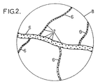
考慮される例において、画像化装置1はさらに図2に表されるような観察領域の画像を表示するためのスクリーン5を備え、またはその他どのようなユーザーインターフェースを備えてもよく、図2は人体2の毛細血管6を示しており、毛細血管には微小な泡7または事前に環境2(例えば血流)に注入された類似の物体が循環し、トランスデューサのアレイ3によって放出された超音波を後方散乱することが可能な散乱体を構成する。
In the example considered, the imaging device 1 may further comprise a screen 5 for displaying an image of the observation region as represented in FIG. 2, or any other user interface, FIG. Shown are
これらの微小な泡は、例えば、非特許文献1に記載された種類であることができる。 These fine bubbles can be of the type described in Non-Patent Document 1, for example.
制御処理装置4は、以下からなる画像化方法を実行するように適合され(プログラムされ)ている。
(a)制御処理装置4が未処理の信号を記録する複数の測定段階、
(a’)微小な泡の破壊段階によって分離することが可能なこれらの測定段階、
(b)未処理の信号を差分処理して微小な泡の破壊の間に構成される差分ターゲットを表す差分信号を得る少なくとも1つの段階、
(c)放物線曲線が各差分信号にフィットされる少なくとも1つの調整段階、及び
(d)差分ターゲットの位置に対応する各放物線曲線の頂点が決定される少なくとも1つの位置決定段階。
The control processor 4 is adapted (programmed) to carry out an imaging method comprising:
(A) a plurality of measurement stages in which the control processor 4 records unprocessed signals;
(A ′) these measurement stages which can be separated by a microbubble breaking stage,
(B) at least one stage to differentially process the raw signal to obtain a differential signal representative of the differential target constructed during the destruction of the microbubbles;
(C) at least one adjustment stage in which a parabola curve is fitted to each difference signal, and (d) at least one position determination stage in which the apex of each parabola curve corresponding to the position of the difference target is determined.
(a)測定段階
本方法は、ほぼ毎ミリ秒またはそれ以下で繰り返されるN個、例えば約400個の測定段階である、複数の連続する測定段階を備える。
(A) Measurement steps The method comprises a plurality of successive measurement steps, N, for example about 400 measurement steps repeated approximately every millisecond or less.
これらの各測定段階において、入射超音波はトランスデューサのアレイ3によって観察領域8に、例えば平面波または可能であれば集束波で送信され、次いで各トランスデューサT1からTnによって受信され環境の散乱体によって入射波から反響した反射超音波を表す未処理の信号Sj(i,t)が記録され、iは各トランスデューサを示す指標であり、jは各測定段階を示す指標であり、tは時間を示す。
In each of these measurement phase, the
超音波画像の生成は例えばビームフォーミングによる未処理信号の処理を必要とするため、未処理の信号は超音波画像ではないことに注意しなければならない。 It should be noted that the generation of an ultrasound image requires processing of an unprocessed signal, for example by beamforming, so that the unprocessed signal is not an ultrasound image.
しかしながら、測定段階の少なくとも1つは、制御処理装置4によって従来のミリメートルの解像度で観察領域8の超音波画像を確立するために用いられてもよく、次いでこの画像が後述する段階(e)で得られる差分ターゲットの位置に重畳される。超音波画像は制御処理装置4によって多数の測定段階においてまたは各測定段階において生成されることができ、この方法の経過の間に環境2のありうる変形を考慮に入れることができる。
However, at least one of the measurement steps may be used by the control processor 4 to establish an ultrasound image of the
本発明において、少ない数Cの微小な泡が1つの測定段階から次の測定段階の間に破壊される。Cは1つの測定段階から次の測定段階の間に観察領域8において破壊される微小な泡の最大の数である。破壊された微小な泡のそれぞれを、本明細書においては差分ターゲットと呼ぶ。より一般的には、差分ターゲットは1つの測定段階から次の測定段階の間に消滅しまたは出現する散乱体であることができ、すなわち、1つの測定段階の間に観察領域に存在し次の測定段階の時には存在しない散乱体である。
In the present invention, a small number C of fine bubbles are destroyed from one measurement stage to the next. C is the maximum number of microbubbles broken in the
数Cは、一般にたかだか2に等しく、好適にはたかだか1に等しい。より一般的には、数CはたかだかINT(A/(5λ)2)+1に等しいことができ、ここで、Aは観察領域の面積であり、INTは整数を返す関数である。 The number C is generally at most equal to 2, preferably at most equal to 1. More generally, the number C can be at most equal to INT (A / (5λ) 2 ) +1, where A is the area of the observation region and INT is a function that returns an integer.
微小な泡の破壊
微小な泡を破壊するために、制御処理ユニット4はトランスデューサのアレイ3に最大数Cの微小な泡を破壊するのにちょうど十分な強度の超音波(例えば平面波または可能であれば集束波)を送信させる。この強度は、初期調整段階において経験的に決定される(この場合各超音波の送出において破壊される微小な泡の量は超音波検査法によって決定される)か、または動作条件に従って前もって(経験的にまたは計算によって)決定されることができる。
Microbubble destruction To destroy microbubbles, the control processing unit 4 causes the transducer array 3 to have ultrasonic waves (e.g. plane waves or possibly if possible) just enough to destroy a maximum number C of microbubbles. For example, a focused wave). This strength is determined empirically during the initial adjustment phase (in this case the amount of microbubbles destroyed in each ultrasound delivery is determined by ultrasonography) or in advance according to operating conditions (experience Or by calculation).
各送出において1つまたは複数の微小な泡を破壊するのに用いられるこれらの超音波は、各測定段階で放出される入射波であるか、または測定段階の入射波よりも強度の大きな破壊的超音波のいずれかであることができ、前者の場合この方法は特定の微小な泡の破壊段階を備えず、後者の場合、破壊的音波のそれぞれは2つの測定段階(a)の間に挿入される微小な泡の破壊段階(a’)において放出される。 These ultrasonic waves used to break one or more microbubbles at each delivery are incident waves emitted at each measurement stage or are more destructive than the incident waves at the measurement stage. In the former case, this method does not comprise a specific microbubble destruction stage, in the latter case each of the destructive acoustic waves is inserted between two measurement stages (a) Is released in the microbubble destruction stage (a ′).
(b)差分処理段階
未処理の信号Sj(i,t)を記録した後、次の段階は差分処理段階であり、全ての未処理の信号を記録した後に開始してもよく、または単純に第1の未処理の信号を記録した後に開始してもよく、これは次いで部分的に他の未処理の信号が記録されている間に行う。
(B) Difference processing stage After recording the unprocessed signal S j (i, t), the next stage is the difference processing stage, which may start after recording all the unprocessed signals, or simply May begin after the first raw signal is recorded, which is then partially done while another raw signal is being recorded.
この差分処理段階において、制御処理装置4は、指標jの連続する測定段階に対応する未処理の信号Sj(i,t)を比較し、連続する測定段階からの未処理の信号間の変化を表す差分信号Vj(i,t)を抽出する。これらの信号は、個別の1回限りの事象に対応し、一般に各受信チャネル、すなわち各トランスデューサにパルスとして入る。 In this difference processing stage, the control processor 4 compares the unprocessed signal S j (i, t) corresponding to the successive measurement stages of the index j and changes between the unprocessed signals from the successive measurement stages. The differential signal V j (i, t) representing is extracted. These signals correspond to individual one-off events and generally pulse as each receive channel, ie each transducer.
この差分処理段階は、それ自体複数の副段階を備えてもよく、それらは例えば以下のように共に結合されている。 This differential processing stage may itself comprise a plurality of sub-stages, which are coupled together, for example as follows.
(b1)未処理の差分信号を計算する副段階
この副段階において、制御処理装置4は、未処理の差分信号Vbj(i,t)を計算する。
(B1) Sub-stage for calculating the unprocessed difference signal In this sub-stage, the control processing device 4 calculates the unprocessed difference signal Vb j (i, t).
これらの未処理の差分信号Vbj(i,t)は、例えば未処理の信号Sj(i、t)から2つの方法で得ることができる。
−1つは、差Vbj(i,t)=Sj(i,t)−Sj−1(i,t)をj=2からNまで計算することによる。
−もう1つは、未処理の信号Sj(i,t)をハイパスフィルタリングすることによるものであり、フィルタリングはjについて異なる測定段階jにおいて得られた未処理の信号間の急速な変化のみをとどめるように行われる。
These unprocessed differential signals Vb j (i, t) can be obtained from the unprocessed signals S j (i, t) in two ways, for example.
−1 is by calculating the difference Vb j (i, t) = S j (i, t) −S j−1 (i, t) from j = 2 to N.
The other is by high-pass filtering the raw signal S j (i, t), which filters only the rapid changes between the raw signals obtained at different measurement stages j for j. It is done to stay.
(b2)tについて一時的なローパスフィルタリング
制御処理装置4は、可能ならば次いでtについて未処理の差分信号Vbj(i,t)の一時的なローパスフィルタリングの副段階を実施するものであってもよい。
(B2) Temporary low-pass filtering for t The control processor 4 then performs a sub-stage of temporary low-pass filtering of the unprocessed difference signal Vb j (i, t) for t, if possible. Also good.
(b3)境界の決定
制御処理装置4は、次いで境界決定の副段階を実施してもよく、この段階においては、差分信号Vj(i,t)が以下によって決定される。
−副段階(b2)からのフィルターされた未処理の差分信号Vbj(i,t)の一時的な境界Vej(i,t)を計算する。
−次いで、iについて一時的な境界Vej(i,t)のローパスフィルタリングを実施し、差分信号Vj(i,t)を得る。
(B3) Boundary determination The control processor 4 may then perform a boundary determination sub-stage, in which the difference signal V j (i, t) is determined by:
Calculate the temporary boundary Ve j (i, t) of the filtered raw difference signal Vb j (i, t) from sub-stage (b2).
-Then, a low-pass filtering of the temporary boundary Ve j (i, t) is performed for i to obtain the difference signal V j (i, t).
(c)調整段階
制御処理装置4は次いで調整段階を実施し、この段階において各差分信号Vj(i,t)に対応する少なくとも1つの関数y=Pj(x)が決定される。
(C) Adjustment stage The control processor 4 then carries out an adjustment stage, in which at least one function y = P j (x) corresponding to each difference signal V j (i, t) is determined.
このようにして、制御処理装置4は、まず各トランスデューサi及び各測定段階j>1に対してVj(i,t)の最大値Vj(i,ti)を決定する。 In this way, the control processing device 4 first determines the maximum value V j (i, t i ) of V j (i, t) for each transducer i and each measurement stage j> 1.
次いで、制御処理装置4は、観察領域8の対応する点Dj(xi,yi)を推定し、ここで、xiは、伝搬の方向に対して垂直な各トランスデューサiの位置を示す空間変数(すなわち、本明細書で考慮されているような場合には単純にx軸に沿ったx座標からなる1次元変数であり、2次元アレイ3の場合には2つの軸に沿った2つの座標を備える2次元変数である)であり、
−yiは、伝搬時間tiに対応する伝搬の方向に沿った点の位置を示す座標であり、それに関してVj(i,t)はその最大値となる(yi=c×ti/2であり、cは超音波の速度である)。
Next, the control processing device 4 estimates a corresponding point D j (x i , y i ) of the
-Yi is a coordinate indicating the position of a point along the direction of propagation corresponding to the propagation time t i , and V j (i, t) is its maximum value (y i = c × t i / 2 and c is the ultrasonic velocity).
より一般的には、これらの点Dj(xi,yi)は、信号Vj(i,t)の伝搬時間tiの特性に対応する伝搬方向に沿った点の位置を示す値yiと共に決定することができることに注意すべきである。この時間は、例えば、上述の信号Vj(i,t)の最大値に対応し、または信号Vj(i,t)の波面に対応し、またはその他である。 More generally, these points D j (x i, y i ) is the signal V j (i, t) the value indicating the position of a point along the propagation direction corresponding to the characteristics of the propagation time t i of y Note that it can be determined with i . This time corresponds, for example, to the maximum value of the signal V j (i, t) described above, or to the wavefront of the signal V j (i, t), or otherwise.
次いで、制御処理装置4は、各測定段階j>1に対して、点Dj(xi,yi)に対する偏差を最小にするように調整された関数y=Pj(x)を決定する(例えば、以下の数式の二乗偏差が最小化される)。 The control processor 4 then determines for each measurement stage j> 1 a function y = P j (x) adjusted to minimize the deviation with respect to the point D j (x i , y i ). (For example, the squared deviation of the following formula is minimized).

関数y=Pj(x)は、xについての連続関数であり、好適には2次多項式関数(放物線)である。この関数は、本明細書に記載されたように線形アレイ3についての放物線または2次元アレイ3についての放物面に対応する。 The function y = P j (x) is a continuous function with respect to x, preferably a quadratic polynomial function (parabola). This function corresponds to a parabola for a linear array 3 or a paraboloid for a two-dimensional array 3 as described herein.
(d)位置決定段階
最後に、制御処理装置4は、各測定段階j>1の差分ターゲットに関して位置決定段階を実施する。または簡潔には、測定段階j−1とjとの間に消滅した微小な泡の位置を決定する。この目的を達成するために、制御処理装置4は、上述の関数Pjの頂点Aj(x0,y0)を決定し、この頂点は差分ターゲットの位置に対応し、用いられる超音波の波長よりも明確に小さい解像度、例えばλ/50からλ/200のオーダーで決定される。
(D) Position Determination Stage Finally, the control processing device 4 performs a position determination stage for each differential stage j> 1 difference target. Or briefly, the position of the microbubbles disappeared between the measurement steps j-1 and j is determined. In order to achieve this purpose, the control processing device 4 determines the vertex A j (x 0 , y 0 ) of the above-mentioned function P j , which corresponds to the position of the difference target, and the ultrasonic wave used The resolution is determined to be clearly smaller than the wavelength, for example, on the order of λ / 50 to λ / 200.
連続する差分ターゲットの位置Aj(x0,y0)は、次いで有利には観察領域8の画像上にプロットすることができる。この画像は例えば上述したように超音波検査法によって得られ(または観察領域のその他どのような画像でもよく、例えば放射線、MRIまたはその他の手段によって得られる)、観察領域8の非常に解像度の高い画像を得る。
The successive differential target positions A j (x 0 , y 0 ) can then advantageously be plotted on the image of the
上述の段階(c)及び(d)は、全ての差分信号が決定された後に実施されてもよく、またはこれらの差分信号Vj(i,t)が計算されているとき及びされるときに実施されてもよい。 Steps (c) and (d) described above may be performed after all the difference signals have been determined, or when these difference signals V j (i, t) are being calculated. May be implemented.
上述の差分信号は、微小な泡またはその他の散乱体、例えば特にトランスデューサのアレイ3を用いる集束超音波または光音響効果によって測定段階の間に得られるキャビテーションの泡の生成に対応することもできることも注意されるであろう。 The differential signal described above can also correspond to the generation of cavitation bubbles obtained during the measurement phase by focused ultrasound or photoacoustic effects using microbubbles or other scatterers such as in particular an array 3 of transducers. It will be noted.
1 装置
2 環境
3 アレイ
4 制御処理装置
5 スクリーン
6 毛細血管
7 散乱体
8 観察領域
1 device 2 environment 3 array 4 control processing device 5
Claims (12)
前記制御処理装置(4)が、複数の連続する測定段階において、
−トランスデューサの前記アレイ(3)に、各測定段階において前記観察領域(8)内に中心波長λの入射超音波を放出させ、
−次いで前記各トランスデューサ(T1−Tn)によって受信され前記環境の前記微小な泡(7)によって入射波から反響された反射超音波を表す未処理の信号Sj(i,t)を記録するように適合され、ここでiが各センサを示す指標であり、jが各測定段階を示す指標であり、tが時間を示し、
トランスデューサの前記アレイ(3)が、少なくとも1つの方向に沿って延設し、前記入射波が、トランスデューサの前記アレイに対して垂直な伝搬の方向に主に伝搬し、
前記制御処理装置(4)が、1つの測定段階から別の測定段階への間にトランスデューサの前記アレイ(3)に数Cの前記微小な泡(7)を破壊するのに十分なだけの強度の超音波を送信させ、破壊された前記微小な泡(7)のそれぞれが差分ターゲットを構成するように適合されたことを特徴とし、
前記数CがたかだかINT(A/(5λ)2)+1に等しく、ここで、Aが前記観察領域の表面積であり、
前記制御処理装置(4)が、次の各段階、
−指標jの連続する測定段階に対応する未処理の信号Sj(i,t)が比較されて連続する測定段階から得られた未処理の信号間の変化を表す差分信号Vj(i,t)を抽出する差分処理段階、
−各差分信号Vj(i,t)に対応する少なくとも1つの関数y=Pj(x)が決定され、ここで、xが前記伝搬の方向に対して垂直な位置を示す空間変数であり、yが、伝搬時間tに対応する伝搬方向に沿った点の位置を示す座標である、調整段階、
−前記差分ターゲットの位置に対応する前記関数Pjの頂点Aj(x0,y0)が決定される位置決定段階、をさらに実行するようにさらに適合されたことを特徴とする、装置。 Of transducers (T 1 to T n ) controlled by a control processor (4) adapted to image an observation region (8) in an imaged environment (2) containing microbubbles (7) an apparatus Ru comprising an array (3),
In the control processing device (4), in a plurality of successive measurement steps,
-Causing the array of transducers (3) to emit incident ultrasound of central wavelength λ into the observation region (8) at each measurement stage;
-Record the raw signal S j (i, t) representing the reflected ultrasound received from each transducer (T 1 -T n ) and then reflected from the incident wave by the microbubbles (7) in the environment Where i is an index indicating each sensor, j is an index indicating each measurement stage, t is time,
The array (3) of transducers extends along at least one direction, and the incident wave propagates mainly in the direction of propagation perpendicular to the array of transducers;
Intensity sufficient for the control processor (4 ) to break a few C of the microbubbles (7) in the array (3) of transducers from one measurement stage to another Characterized in that each of the broken microbubbles (7) is adapted to constitute a differential target,
The number C is at most INT (A / (5λ) 2 ) equal to +1, where, A is a table area of the observation area,
The control processing device (4) has the following steps:
The difference signal V j (i, i, t) representing the change between the unprocessed signals obtained from the successive measurement stages by comparing the unprocessed signals S j (i, t) corresponding to the successive measurement stages of the index j a differential processing stage for extracting t),
At least one function y = P j (x) corresponding to each difference signal V j (i, t) is determined, where x is a spatial variable indicating a position perpendicular to the direction of propagation , Y is a coordinate that indicates the position of a point along the propagation direction corresponding to the propagation time t,
The apparatus is further adapted to further perform a position determining step in which a vertex A j (x 0 , y 0 ) of the function P j corresponding to the position of the difference target is determined.
Applications Claiming Priority (3)
| Application Number | Priority Date | Filing Date | Title |
|---|---|---|---|
| FR1060633A FR2969350B1 (en) | 2010-12-16 | 2010-12-16 | METHOD AND DEVICE FOR SOUND IMAGING. |
| FR1060633 | 2010-12-16 | ||
| PCT/FR2011/052810 WO2012080614A1 (en) | 2010-12-16 | 2011-11-29 | Method and device for ultrasound imaging |
Publications (3)
| Publication Number | Publication Date |
|---|---|
| JP2013545568A JP2013545568A (en) | 2013-12-26 |
| JP2013545568A5 JP2013545568A5 (en) | 2014-11-06 |
| JP5947312B2 true JP5947312B2 (en) | 2016-07-06 |
Family
ID=44201042
Family Applications (1)
| Application Number | Title | Priority Date | Filing Date |
|---|---|---|---|
| JP2013543853A Active JP5947312B2 (en) | 2010-12-16 | 2011-11-29 | Equipment for ultrasound imaging |
Country Status (7)
| Country | Link |
|---|---|
| US (1) | US9329260B2 (en) |
| EP (1) | EP2652517B1 (en) |
| JP (1) | JP5947312B2 (en) |
| ES (1) | ES2523982T3 (en) |
| FR (1) | FR2969350B1 (en) |
| IL (1) | IL226916A (en) |
| WO (1) | WO2012080614A1 (en) |
Families Citing this family (3)
| Publication number | Priority date | Publication date | Assignee | Title |
|---|---|---|---|---|
| US10751028B2 (en) | 2016-04-01 | 2020-08-25 | The Board Of Trustees Of The Leland Stanford Junior University | Coherence-based beamforming for improved microbubble detection in contrast enhanced ultrasound |
| JP6912561B2 (en) | 2016-09-16 | 2021-08-04 | アンスティチュ ナショナル ドゥ ラ サンテ エ ドゥ ラ ルシェルシュ メディカル | Methods and related equipment for imaging samples with blood |
| US20200107817A1 (en) | 2017-03-22 | 2020-04-09 | Institut National De La Sante Et De La Recherche Medical (Inserm) | Method for imaging an area of a medium with ultrasound contrast agents and associated device |
Family Cites Families (11)
| Publication number | Priority date | Publication date | Assignee | Title |
|---|---|---|---|---|
| US7841982B2 (en) * | 1995-06-22 | 2010-11-30 | Techniscan, Inc. | Apparatus and method for imaging objects with wavefields |
| JP3862838B2 (en) * | 1997-11-26 | 2006-12-27 | 株式会社東芝 | Ultrasonic diagnostic equipment |
| US6398735B1 (en) * | 2000-03-07 | 2002-06-04 | Koninklijke Philips Electronics N.V. | Detecting a relative level of an ultrasound imaging contrast agent |
| EP1715897B2 (en) * | 2004-01-20 | 2013-10-30 | Sunnybrook and Women's College Health Sciences Centre | High frequency ultrasound imaging using contrast agents |
| JP4521204B2 (en) * | 2004-02-27 | 2010-08-11 | 株式会社東芝 | Ultrasonic diagnostic apparatus, image processing apparatus, and ultrasonic imaging method |
| US7850611B2 (en) * | 2004-09-20 | 2010-12-14 | Innervision Medical Technologies Inc. | System and methods for improved ultrasound imaging |
| US7862508B2 (en) * | 2004-09-20 | 2011-01-04 | Innervision Medical Technologies Inc. | Systems and methods for ultrasound imaging |
| US9439571B2 (en) * | 2006-01-20 | 2016-09-13 | Washington University | Photoacoustic and thermoacoustic tomography for breast imaging |
| US20070287912A1 (en) * | 2006-05-31 | 2007-12-13 | Khuri-Yakub Butrus T | Functional imaging using capacitive micromachined ultrasonic transducers |
| US20080311045A1 (en) * | 2007-06-06 | 2008-12-18 | Biovaluation & Analysis, Inc. | Polymersomes for Use in Acoustically Mediated Intracellular Drug Delivery in vivo |
| US8306293B2 (en) * | 2008-05-15 | 2012-11-06 | University Of Virginia Patent Foundation | Reduction of echo decorrelation facilitating motion estimation |
-
2010
- 2010-12-16 FR FR1060633A patent/FR2969350B1/en not_active Expired - Fee Related
-
2011
- 2011-11-29 ES ES11799794.0T patent/ES2523982T3/en active Active
- 2011-11-29 US US13/993,224 patent/US9329260B2/en active Active
- 2011-11-29 EP EP11799794.0A patent/EP2652517B1/en active Active
- 2011-11-29 JP JP2013543853A patent/JP5947312B2/en active Active
- 2011-11-29 WO PCT/FR2011/052810 patent/WO2012080614A1/en active Application Filing
-
2013
- 2013-06-13 IL IL226916A patent/IL226916A/en active IP Right Grant
Also Published As
| Publication number | Publication date |
|---|---|
| IL226916A (en) | 2017-01-31 |
| EP2652517A1 (en) | 2013-10-23 |
| EP2652517B1 (en) | 2014-10-08 |
| WO2012080614A1 (en) | 2012-06-21 |
| JP2013545568A (en) | 2013-12-26 |
| US20130301382A1 (en) | 2013-11-14 |
| US9329260B2 (en) | 2016-05-03 |
| FR2969350B1 (en) | 2013-01-11 |
| FR2969350A1 (en) | 2012-06-22 |
| ES2523982T3 (en) | 2014-12-03 |
Similar Documents
| Publication | Publication Date | Title |
|---|---|---|
| JP6389213B2 (en) | Mapping and characterization of cavitation activities | |
| US6454713B1 (en) | Ultrasound therapeutic apparatus | |
| US6334846B1 (en) | Ultrasound therapeutic apparatus | |
| KR100990011B1 (en) | Contrast agent manipulation with medical ultrasound imaging | |
| EP1795131B1 (en) | High intensity focused ultrasound system | |
| CN109689160B (en) | Therapeutic ultrasound with reduced interference from microbubbles | |
| JP6288996B2 (en) | Ultrasonic diagnostic apparatus and ultrasonic imaging program | |
| JP2008539908A (en) | Ultrasound diagnostic and treatment equipment | |
| KR20150070859A (en) | Method and apparatus for obtaining elasticity information of interest of region using shear wave | |
| EP2725984A1 (en) | Object-pose-based initialization of an ultrasound beamformer | |
| JP5235477B2 (en) | Ultrasonic image forming method and ultrasonic apparatus | |
| JP6808362B2 (en) | Devices and methods for hybrid optical acoustic tomography and ultrasonography | |
| KR20170077038A (en) | Information acquisition apparatus, information acquisition method, and related program | |
| CN107205720B (en) | Ultrasonic adaptive beam forming method and application thereof to transcranial imaging | |
| JP5947312B2 (en) | Equipment for ultrasound imaging | |
| CN109259801B (en) | Shear wave elastic imaging method and device | |
| KR102545007B1 (en) | Ultrasound imaging apparatus and controlling method for the same | |
| US11119199B2 (en) | Acoustic wave image generation apparatus and acoustic wave image generation method | |
| CN110392553B (en) | Positioning device and system for positioning acoustic sensors | |
| KR20130020054A (en) | Method for generating ultrasound image and ultrasound system | |
| KR20150040670A (en) | Apparatus and method for obtaining elastic feature of object | |
| KR20230091966A (en) | Image Composite for Mixed Transducer Arrays | |
| JP2013545568A5 (en) | ||
| US20190069875A1 (en) | Ultrasound system for cerebral blood flow imaging and microbubble-enhanced blood clot lysis | |
| KR102132072B1 (en) | Ultrasonic system and operation method thereof |
Legal Events
| Date | Code | Title | Description |
|---|---|---|---|
| A521 | Request for written amendment filed |
Free format text: JAPANESE INTERMEDIATE CODE: A523 Effective date: 20140917 |
|
| A621 | Written request for application examination |
Free format text: JAPANESE INTERMEDIATE CODE: A621 Effective date: 20140917 |
|
| A977 | Report on retrieval |
Free format text: JAPANESE INTERMEDIATE CODE: A971007 Effective date: 20150623 |
|
| A131 | Notification of reasons for refusal |
Free format text: JAPANESE INTERMEDIATE CODE: A131 Effective date: 20150803 |
|
| A521 | Request for written amendment filed |
Free format text: JAPANESE INTERMEDIATE CODE: A523 Effective date: 20151102 |
|
| TRDD | Decision of grant or rejection written | ||
| A01 | Written decision to grant a patent or to grant a registration (utility model) |
Free format text: JAPANESE INTERMEDIATE CODE: A01 Effective date: 20160509 |
|
| A61 | First payment of annual fees (during grant procedure) |
Free format text: JAPANESE INTERMEDIATE CODE: A61 Effective date: 20160602 |
|
| R150 | Certificate of patent or registration of utility model |
Ref document number: 5947312 Country of ref document: JP Free format text: JAPANESE INTERMEDIATE CODE: R150 |
|
| R250 | Receipt of annual fees |
Free format text: JAPANESE INTERMEDIATE CODE: R250 |
|
| R250 | Receipt of annual fees |
Free format text: JAPANESE INTERMEDIATE CODE: R250 |
|
| R250 | Receipt of annual fees |
Free format text: JAPANESE INTERMEDIATE CODE: R250 |
|
| R250 | Receipt of annual fees |
Free format text: JAPANESE INTERMEDIATE CODE: R250 |
|
| S111 | Request for change of ownership or part of ownership |
Free format text: JAPANESE INTERMEDIATE CODE: R313115 |
|
| R350 | Written notification of registration of transfer |
Free format text: JAPANESE INTERMEDIATE CODE: R350 |
|
| R250 | Receipt of annual fees |
Free format text: JAPANESE INTERMEDIATE CODE: R250 |