JP6912561B2 - Methods and related equipment for imaging samples with blood - Google Patents
Methods and related equipment for imaging samples with blood Download PDFInfo
- Publication number
- JP6912561B2 JP6912561B2 JP2019514807A JP2019514807A JP6912561B2 JP 6912561 B2 JP6912561 B2 JP 6912561B2 JP 2019514807 A JP2019514807 A JP 2019514807A JP 2019514807 A JP2019514807 A JP 2019514807A JP 6912561 B2 JP6912561 B2 JP 6912561B2
- Authority
- JP
- Japan
- Prior art keywords
- blood
- imaging
- contribution
- interest
- observations
- Prior art date
- Legal status (The legal status is an assumption and is not a legal conclusion. Google has not performed a legal analysis and makes no representation as to the accuracy of the status listed.)
- Active
Links
Images


Classifications
-
- A—HUMAN NECESSITIES
- A61—MEDICAL OR VETERINARY SCIENCE; HYGIENE
- A61B—DIAGNOSIS; SURGERY; IDENTIFICATION
- A61B8/00—Diagnosis using ultrasonic, sonic or infrasonic waves
- A61B8/06—Measuring blood flow
-
- A—HUMAN NECESSITIES
- A61—MEDICAL OR VETERINARY SCIENCE; HYGIENE
- A61B—DIAGNOSIS; SURGERY; IDENTIFICATION
- A61B8/00—Diagnosis using ultrasonic, sonic or infrasonic waves
- A61B8/08—Detecting organic movements or changes, e.g. tumours, cysts, swellings
- A61B8/0833—Detecting organic movements or changes, e.g. tumours, cysts, swellings involving detecting or locating foreign bodies or organic structures
- A61B8/085—Detecting organic movements or changes, e.g. tumours, cysts, swellings involving detecting or locating foreign bodies or organic structures for locating body or organic structures, e.g. tumours, calculi, blood vessels, nodules
-
- A—HUMAN NECESSITIES
- A61—MEDICAL OR VETERINARY SCIENCE; HYGIENE
- A61B—DIAGNOSIS; SURGERY; IDENTIFICATION
- A61B8/00—Diagnosis using ultrasonic, sonic or infrasonic waves
- A61B8/08—Detecting organic movements or changes, e.g. tumours, cysts, swellings
- A61B8/0891—Detecting organic movements or changes, e.g. tumours, cysts, swellings for diagnosis of blood vessels
-
- A—HUMAN NECESSITIES
- A61—MEDICAL OR VETERINARY SCIENCE; HYGIENE
- A61B—DIAGNOSIS; SURGERY; IDENTIFICATION
- A61B8/00—Diagnosis using ultrasonic, sonic or infrasonic waves
- A61B8/13—Tomography
- A61B8/14—Echo-tomography
-
- A—HUMAN NECESSITIES
- A61—MEDICAL OR VETERINARY SCIENCE; HYGIENE
- A61B—DIAGNOSIS; SURGERY; IDENTIFICATION
- A61B8/00—Diagnosis using ultrasonic, sonic or infrasonic waves
- A61B8/13—Tomography
- A61B8/14—Echo-tomography
- A61B8/145—Echo-tomography characterised by scanning multiple planes
-
- A—HUMAN NECESSITIES
- A61—MEDICAL OR VETERINARY SCIENCE; HYGIENE
- A61B—DIAGNOSIS; SURGERY; IDENTIFICATION
- A61B8/00—Diagnosis using ultrasonic, sonic or infrasonic waves
- A61B8/44—Constructional features of the ultrasonic, sonic or infrasonic diagnostic device
- A61B8/4483—Constructional features of the ultrasonic, sonic or infrasonic diagnostic device characterised by features of the ultrasound transducer
- A61B8/4494—Constructional features of the ultrasonic, sonic or infrasonic diagnostic device characterised by features of the ultrasound transducer characterised by the arrangement of the transducer elements
-
- A—HUMAN NECESSITIES
- A61—MEDICAL OR VETERINARY SCIENCE; HYGIENE
- A61B—DIAGNOSIS; SURGERY; IDENTIFICATION
- A61B8/00—Diagnosis using ultrasonic, sonic or infrasonic waves
- A61B8/48—Diagnostic techniques
- A61B8/488—Diagnostic techniques involving Doppler signals
-
- A—HUMAN NECESSITIES
- A61—MEDICAL OR VETERINARY SCIENCE; HYGIENE
- A61B—DIAGNOSIS; SURGERY; IDENTIFICATION
- A61B8/00—Diagnosis using ultrasonic, sonic or infrasonic waves
- A61B8/52—Devices using data or image processing specially adapted for diagnosis using ultrasonic, sonic or infrasonic waves
- A61B8/5207—Devices using data or image processing specially adapted for diagnosis using ultrasonic, sonic or infrasonic waves involving processing of raw data to produce diagnostic data, e.g. for generating an image
-
- G—PHYSICS
- G01—MEASURING; TESTING
- G01S—RADIO DIRECTION-FINDING; RADIO NAVIGATION; DETERMINING DISTANCE OR VELOCITY BY USE OF RADIO WAVES; LOCATING OR PRESENCE-DETECTING BY USE OF THE REFLECTION OR RERADIATION OF RADIO WAVES; ANALOGOUS ARRANGEMENTS USING OTHER WAVES
- G01S15/00—Systems using the reflection or reradiation of acoustic waves, e.g. sonar systems
- G01S15/88—Sonar systems specially adapted for specific applications
- G01S15/89—Sonar systems specially adapted for specific applications for mapping or imaging
- G01S15/8906—Short-range imaging systems; Acoustic microscope systems using pulse-echo techniques
- G01S15/8909—Short-range imaging systems; Acoustic microscope systems using pulse-echo techniques using a static transducer configuration
- G01S15/8915—Short-range imaging systems; Acoustic microscope systems using pulse-echo techniques using a static transducer configuration using a transducer array
- G01S15/8925—Short-range imaging systems; Acoustic microscope systems using pulse-echo techniques using a static transducer configuration using a transducer array the array being a two-dimensional transducer configuration, i.e. matrix or orthogonal linear arrays
-
- G—PHYSICS
- G01—MEASURING; TESTING
- G01S—RADIO DIRECTION-FINDING; RADIO NAVIGATION; DETERMINING DISTANCE OR VELOCITY BY USE OF RADIO WAVES; LOCATING OR PRESENCE-DETECTING BY USE OF THE REFLECTION OR RERADIATION OF RADIO WAVES; ANALOGOUS ARRANGEMENTS USING OTHER WAVES
- G01S15/00—Systems using the reflection or reradiation of acoustic waves, e.g. sonar systems
- G01S15/88—Sonar systems specially adapted for specific applications
- G01S15/89—Sonar systems specially adapted for specific applications for mapping or imaging
- G01S15/8906—Short-range imaging systems; Acoustic microscope systems using pulse-echo techniques
- G01S15/8909—Short-range imaging systems; Acoustic microscope systems using pulse-echo techniques using a static transducer configuration
- G01S15/8915—Short-range imaging systems; Acoustic microscope systems using pulse-echo techniques using a static transducer configuration using a transducer array
- G01S15/8927—Short-range imaging systems; Acoustic microscope systems using pulse-echo techniques using a static transducer configuration using a transducer array using simultaneously or sequentially two or more subarrays or subapertures
-
- G—PHYSICS
- G01—MEASURING; TESTING
- G01S—RADIO DIRECTION-FINDING; RADIO NAVIGATION; DETERMINING DISTANCE OR VELOCITY BY USE OF RADIO WAVES; LOCATING OR PRESENCE-DETECTING BY USE OF THE REFLECTION OR RERADIATION OF RADIO WAVES; ANALOGOUS ARRANGEMENTS USING OTHER WAVES
- G01S15/00—Systems using the reflection or reradiation of acoustic waves, e.g. sonar systems
- G01S15/88—Sonar systems specially adapted for specific applications
- G01S15/89—Sonar systems specially adapted for specific applications for mapping or imaging
- G01S15/8906—Short-range imaging systems; Acoustic microscope systems using pulse-echo techniques
- G01S15/8979—Combined Doppler and pulse-echo imaging systems
- G01S15/8981—Discriminating between fixed and moving objects or between objects moving at different speeds, e.g. wall clutter filter
-
- G—PHYSICS
- G01—MEASURING; TESTING
- G01S—RADIO DIRECTION-FINDING; RADIO NAVIGATION; DETERMINING DISTANCE OR VELOCITY BY USE OF RADIO WAVES; LOCATING OR PRESENCE-DETECTING BY USE OF THE REFLECTION OR RERADIATION OF RADIO WAVES; ANALOGOUS ARRANGEMENTS USING OTHER WAVES
- G01S7/00—Details of systems according to groups G01S13/00, G01S15/00, G01S17/00
- G01S7/52—Details of systems according to groups G01S13/00, G01S15/00, G01S17/00 of systems according to group G01S15/00
- G01S7/52017—Details of systems according to groups G01S13/00, G01S15/00, G01S17/00 of systems according to group G01S15/00 particularly adapted to short-range imaging
- G01S7/52077—Details of systems according to groups G01S13/00, G01S15/00, G01S17/00 of systems according to group G01S15/00 particularly adapted to short-range imaging with means for elimination of unwanted signals, e.g. noise or interference
-
- A—HUMAN NECESSITIES
- A61—MEDICAL OR VETERINARY SCIENCE; HYGIENE
- A61B—DIAGNOSIS; SURGERY; IDENTIFICATION
- A61B8/00—Diagnosis using ultrasonic, sonic or infrasonic waves
- A61B8/48—Diagnostic techniques
- A61B8/481—Diagnostic techniques involving the use of contrast agent, e.g. microbubbles introduced into the bloodstream
Description
発明の技術分野
本発明は、生体試料をイメージングするための方法に関係し、試料が拡散体を含む血液および固形組織を含む。本発明は、関連イメージング装置、関連コンピュータ製品プログラムおよび関連コンピュータ読み取り可能な媒体にも関する。
Technical Field of the Invention The present invention relates to a method for imaging a biological sample, the sample comprising blood and solid tissue containing a diffuser. The present invention also relates to related imaging devices, related computer product programs and related computer readable media.
発明の背景
本発明は、ドップラーイメージングの分野に関する。
Background of the Invention The present invention relates to the field of Doppler imaging.
ドップラーイメージングは、2013年3月に刊行されたIEEE Transactions on Ultrasonics, Ferroelectrics, and Frequency Control、第60巻、第3号に発表された「Functional Ultrasound Imaging of the Brain: Theory and Basic Principles」と題されたEmilie Maceらによる記事に説明されるように、特に脳をイメージングするために使用される。
Doppler Imaging is entitled "Functional Ultrasound Imaging of the Brain: Theory and Basic Principles" published in March 2013, IEEE Transactions on Ultrasonics, Ferroelectrics, and Frequency Control,
この記事では、超音波パルスが血管を通っているとき、エネルギーの微小部分が赤血球によって後方散乱され、プローブがこれらのエコーを記録できることが特に説明される。ドップラー超音波イメージングの原理は、そのようなパルス化放射を繰り返し、連続的な後方散乱された信号の時間的変化を検討することによって赤血球の運動を検出することである。 This article specifically explains that when an ultrasonic pulse is passing through a blood vessel, a small portion of energy is backscattered by red blood cells and the probe can record these echoes. The principle of Doppler ultrasound imaging is to detect the movement of red blood cells by repeating such pulsed radiation and examining the temporal changes in the continuous backscattered signal.
信号は、画像の各ピクセルごとに記録される。獲得後、クラッタフィルタ(ハイパスフィルタ)は、組織信号を受け入れないために記録された信号に適用される。フィルタリングされた信号(血液信号と雑音とからなる)が取得される。二つのパラメータ:カラードップラー画像を与える各ピクセルにおける軸血流速度またはパワードップラー画像を与える各ピクセルにおけるドップラー信号の平均強度がフィルタリングされた信号から共通して抽出され、表示される。 The signal is recorded for each pixel of the image. After acquisition, the clutter filter (highpass filter) is applied to the recorded signal to not accept the tissue signal. A filtered signal (consisting of a blood signal and noise) is obtained. Two parameters: Axial blood velocity at each pixel giving a color Doppler image or the average intensity of the Doppler signal at each pixel giving a power Doppler image is commonly extracted and displayed from the filtered signal.
歴史的には、パワードップラーモードは、微小血管をよりよく検出しようとして、カラードップラーモードの後で開発された。実際、血流速度の抽出は、多くの異なる推定量が試されてきたにもかかわらず、雑音に対して非常に敏感である。その上、カラードップラーもエイリアシングに対して敏感であり、それは、エイリアス信号が流れ方向の間違った推定を生むため、医療機関では大きな課題である。比較すると、信号強度の推定が雑音に対してより堅牢であり、エイリアシングに対して比較的敏感でないことが示された。 Historically, Power Doppler mode was developed after Color Doppler mode in an attempt to better detect microvessels. In fact, the extraction of blood flow velocities is very sensitive to noise, even though many different estimators have been tried. Moreover, color Doppler is also sensitive to aliasing, which is a major challenge for medical institutions because alias signals produce false estimates of the direction of flow. By comparison, signal strength estimates were shown to be more robust to noise and relatively insensitive to aliasing.
したがって、パワードップラーは、一定の用途、とりわけ、微小血管を特定することにより適している。パワードップラーは、血流速度に関する情報を与えないが、それは、もう一つの関連する血行力学的パラメータ:ピクセル内の血液量と関連付けられる。一定したヘマトクリット濃度凝集状況およびせん断率の状況では、パワードップラーは、第一近似において、ボクセル内の部分的な血液量に比例する。 Therefore, Power Doppler is more suitable for certain applications, especially for identifying microvessels. Power Doppler does not give information about blood flow velocity, but it is associated with another relevant hemodynamic parameter: blood volume within a pixel. In a constant hematocrit concentration and shear modulus situation, the power Doppler is proportional to the partial blood volume in the voxel in the first approximation.
しかし、流れが十分に遅く、血液信号が壁フィルタによって減衰される場合、血流を雑音と識別することがより難しいことがある。その目的のために、異なる戦略が提案されてきた: However, if the flow is slow enough and the blood signal is attenuated by the wall filter, it can be more difficult to distinguish the blood flow from noise. Different strategies have been proposed for that purpose:
文献国際公開公報第2009/158399 A1号では、「Functional ultrasound imaging of the brain」(Nature methods、第8巻、8号、662〜664ページ、2011年)と題されたE. Maceらによる記事に明らかにされたように、多数の獲得される画像によりパワードップラー画像の信号対雑音比を劇的に増加させるために、複合平面波による超高速イメージングの使用が提案される。類似の開示は、「Ultrafast Compound Doppler Imaging : Providing Full Blood Flow Characterization」と題されたJeremy BERCOFFらによる記事、「4D microvascular imaging based on ultrafast Doppler tomography」と題されたCharlie DEMENEらによる記事、「High sensitivity brain angiography using Ultrafast Doppler」および「Functional Ultrasound Imaging of the Brain : Theory and Basic Principles」とそれぞれ題されたE. Maceらによる記事ならびに「Spatiotemporal Clutter Filtering of Ultrafast Ultrasound Data Highly Increases Doppler and Ultrasound Sensitivity」と題されたCharlie DEMENEらによるもう一つの記事から公知である。「Coherent flow power doppler (CFPD): flow detection using spatial coherence beamforming」(IEEE Transactions on Ultrasonics, Ferroelectrics, and Frequency Control、第62巻、第6号、1022〜1035ページ、2015年6月)と題されたY. L. LiおよびJ. J. Dahlによる記事に記載されたように、パワードップラー画像の熱雑音をさらに低減するための隣接受信チャネルの共分散に基づく処理が文献国際公開公報第2014/193945 A1号から公知である。 In the International Publication No. 2009/158399 A1, an article by E. Mace et al. entitled "Functional ultrasound imaging of the brain" (Nature methods, Vol. 8, No. 8, pp. 662-664, 2011) As revealed, the use of ultrafast imaging with composite plane waves is proposed to dramatically increase the signal-to-noise ratio of power Doppler images with a large number of acquired images. Similar disclosures include an article by Jeremy BERCOFF et al. entitled "Ultrafast Compound Doppler Imaging: Providing Full Blood Flow characterization", an article by Charlie DEMENE et al. entitled "4D microvascular imaging based on ultrafast Doppler tomography", and "High sensitivity". An article by E. Mace et al. entitled "brain angiography using Ultrafast Doppler" and "Functional Ultrasound Imaging of the Brain: Theory and Basic Principles" and "Spatiotemporal Clutter Filtering of Ultrafast Ultrasound Data Highly Increases Doppler and Ultrasound Sensitivity" respectively. It is known from another article by Charlie DEMENE et al. Titled "Coherent flow power doppler (CFPD): flow detection using spatial coherence beamforming" (IEEE Transactions on Ultrasonics, Ferroelectrics, and Frequency Control, Vol. 62, No. 6, pp. 1022-1035, June 2015). As described in the article by YL Li and JJ Dahl, processing based on the coherence of adjacent receiving channels to further reduce the thermal noise of the power Doppler image is known from WO 2014/193945 A1. ..
文献国際公開公報第2016046506 A1号では、「Multiplane wave imaging increases signal-to-noise ratio in ultrafast ultrasound imaging」(Physics in Medicine and Biology、第60巻、21号、8549〜8566ページ、2015年)と題されたE. Tiranらによる記事に明らかにされたように、標準的な超高速イメージングシーケンスと比較してパワードップラー画像の信号対雑音比も大幅に改善する新たな超高速シーケンスが提案されている。 In the International Publication No. 20160646506 A1, the title is "Multiplane wave imaging increases signal-to-noise ratio in ultrafast ultrasound imaging" (Physics in Medicine and Biology, Vol. 60, No. 21, pp. 8549-8566, 2015). As revealed in the article by E. Tiran et al., A new ultrasound sequence has been proposed that also significantly improves the signal-to-noise ratio of power Doppler images compared to standard ultrasound imaging sequences. ..
雑音に加えて、壁フィルタを通ることができるゆっくり移動する組織または残響クラッタは、パワードップラー画像の質を落とす、なぜならばゆっくり移動する血液と類似して見えるからである。その点について、C. Demeneらによる記事「Spatiotemporal clutter filtering of ultrafast ultrasound data highly increases Doppler and Ultrasound sensitivity」(IEEE Transactions on Medical Imaging、第1巻、1号、2015年)では、ゆっくりした血流と組織信号との間の分離を劇的に改善し、より高い品質のドップラー画像をもたらす新たな時空間クラッタフィルタが提案された。 In addition to noise, slow-moving tissue or reverberant clutter that can pass through a wall filter degrades the quality of the Power Doppler image, because it looks similar to slow-moving blood. In this regard, C. Demene et al.'S article "Spatiotemporal clutter filtering of ultrafast ultrasound data highly increases Doppler and Ultrasound sensitivity" (IEEE Transactions on Medical Imaging, Vol. 1, No. 1, 2015) describes slow blood flow and tissue. A new spatiotemporal clutter filter has been proposed that dramatically improves the separation from the signal and results in higher quality Doppler images.
パワードップラー画像の信号対雑音比を増加させるもう一つの方法は、血流に注入される超音波造影剤の使用に依存する(「Dynamic microbubble contrast-enhanced US to measure tumor response to targeted therapy: a proposed clinical protocol with results from renal cell carcinoma patients receiving antiangiogenic therapy」(Radiology、2011年)という題のR. Williamsらによる記事)。ドップラー画像の分解能を改善するために、文献国際公開公報第2012/080614 A1号は、個別に空間および時間で正確に追跡され、血管の存在を非常に正確な場所で検出することができる造影剤を使用することを提案している。 Another way to increase the signal-to-noise ratio of a powered Doppler image depends on the use of an ultrasound contrast agent injected into the bloodstream ("Dynamic microbubble contrast-enhanced US to measure tumor response to targeted therapy: a proposed". Clinical protocol with results from renal cell carcinoma patients receiving antiangiogenic therapy ”(Radiology, 2011) by R. Williams et al.). To improve the resolution of Doppler images, WO 2012/08614 A1 is a contrast agent that can be tracked individually in space and time accurately and can detect the presence of blood vessels in a very accurate location. We are proposing to use.
発明の概要
本発明は、血液を含む生体試料のドップラーイメージングを改善することを目的とする。
Outline of the Invention An object of the present invention is to improve Doppler imaging of a biological sample containing blood.
より正確には、本発明は、必ずしも造影剤に依存することなく、ドップラー画像の分解能およびコントラストを改善することを目的とする。本発明は、対象の場所の外側由来の、不完全なイメージング点拡がり関数、例えば、サイドローブによって拡げられる、望ましくない血流成分である血液信号クラッタの存在を低減することを提案する。 More precisely, the present invention aims to improve the resolution and contrast of Doppler images without necessarily relying on contrast media. The present invention proposes to reduce the presence of an incomplete imaging point spread function, eg, a blood signal clutter, which is an unwanted blood flow component that is spread by side lobes, originating from outside the site of interest.
方法は、異なる観測値のセット内で共通して観察され、それらの部分的に無相関化された点拡がり関数の重なったボリューム由来の信号に相当する具体的な対象の場所からの血液信号のゆっくりした時間プロファイルを抽出することをできるようにする。この抽出は、可能である、なぜならばC. Demeneらによって示されたように、特異的な場所由来の血液信号が不規則に流れる拡散体のせいでゆっくりした時間の中で高度に無相関化されて見えるからである(図2)。それ故に、部分的に無相関化された点拡がり関数の重なっていないボリュームは、重なっているボリューム由来の成分とは逆に、特異的な無相関のゆっくりした時間プロファイルを有する。方法は、このように、振動子形状寸法、例えば、スパースアレイ、バーニアアレイまたは行−列アレイが自然に観測値の間に高度に無相関化された点拡がり関数を課すとき、特に興味深い。 The method is commonly observed within different sets of observations and of blood signals from specific target locations that correspond to signals from overlapping volumes of their partially uncorrelated point spread functions. Allows you to extract a slow time profile. This extraction is possible, because, as shown by C. Demene et al., It is highly uncorrelated in slow time due to the diffuser in which blood signals from specific locations flow irregularly. This is because it looks like it has been done (Fig. 2). Therefore, the non-overlapping volume of the partially uncorrelated point spread function has a specific uncorrelated slow time profile, as opposed to the components derived from the overlapping volume. The method is thus particularly interesting when oscillator shape dimensions, such as sparse arrays, vernier arrays or row-column arrays, naturally impose a highly uncorrelated point spread function between the observed values.
この目的に向けて、本発明は、生体試料をイメージングするための方法に関係し、試料が血液拡散体および固形組織拡散体を含み、方法が以下の作業:時間間隔内の非集束超音波の数の割合が毎秒100非集束超音波以上であって、対象の領域内の非集束超音波が時間間隔中に放射される放射作業と、所与の対象の領域の拡散体からの再帰反射波が収集される収集作業と、各観測値が信号を対象の領域の各場所と関連付ける異なる点拡がり関数によって特徴付けられ、信号が場所内の血管の拡散体に対応する第一の寄与、組織拡散体に対応する第二の寄与および場所の外側の血液拡散体と関連付けられる血液信号に対応する第三の寄与を含み、第二および第三の寄与が望ましくない、対象の領域の異なる観測値が収集された再帰反射波に基づいて生成される画像形成作業とを含むイメージング工程を含む。イメージング工程は、対象の領域のM個の時間的実行の観測値セットを取得するためにM回反復され、Mが10以上である。方法は、観測値セットの各々の第二の寄与を低減するためのフィルタリング工程と、対象の領域の各場所ごとに血流信号が推定される推定工程とをさらに含み、推定工程が以下の作業:第一の寄与および第三の寄与を区別するために各観測値セットに統計解析を適用することと、第一の寄与に基づいて血流信号の成分の推定値を計算することとを含む。 To this end, the present invention relates to a method for imaging a biological sample, wherein the sample comprises a blood diffuser and a solid tissue diffuser, and the method is the following task: of unfocused ultrasound within a time interval. Radiation work in which the ratio of numbers is 100 or more unfocused ultrasonic waves per second and the unfocused ultrasonic waves in the target area are emitted during the time interval, and the retroreflected wave from the diffuser in the given target area. Is characterized by a collection operation in which the signal is collected and a different point spread function in which each observation associates the signal with each location in the region of interest, and the signal corresponds to the diffuser of the blood vessels in the location, the first contribution, tissue diffusion. Different observations of the area of interest, including a second contribution corresponding to the body and a third contribution corresponding to the blood signal associated with the blood diffuser outside the location, where the second and third contributions are undesirable. It includes an imaging step that includes an image forming operation that is generated based on the collected retroreflected waves. The imaging step is repeated M times to obtain a set of observations of M temporal runs of the region of interest, where M is 10 or greater. The method further includes a filtering step to reduce the second contribution of each of the observed value sets and an estimation step in which the blood flow signal is estimated for each location in the region of interest, and the estimation steps include: : Includes applying statistical analysis to each set of observations to distinguish between the first and third contributions and calculating estimates of blood flow signal components based on the first contribution. ..
そのような方法は、観測値セット内の第三の寄与の低い共同ばらつきを暗示する、血液信号の空間無相関化に依存する。 Such a method relies on spatial uncorrelated blood signals, implying a third low-contribution joint variability within the set of observations.
方法は、ピクセル内の血液の拡散体に対応する寄与である第一の寄与をクラッタ寄与と区別することを可能にする。より正確には、方法は、固形組織に由来する第二の寄与も対象の場所の外側の血液に由来する第三の寄与もなく、第一の寄与を取得することを可能にする。 The method makes it possible to distinguish the first contribution, which is the contribution corresponding to the blood diffuser within the pixel, from the clutter contribution. More precisely, the method makes it possible to obtain a first contribution without a second contribution from solid tissue or a third contribution from blood outside the site of interest.
第一の寄与と第三の寄与との間の区別は、観測値セットの共同ばらつきに基づく統計解析作業を通じた特異的な場所由来の血液信号の空間無相関化の使用によって可能になる。統計解析は、例として、共役積、相互共分散を算出することによって、または主成分分析(PCA)もしくは特異値分解(SVD)もしくは独立成分分析(ICA)もしくは共同ばらつき分析に基づく任意の他の数学的ツールを実施することによって実施され得る。 The distinction between the first and third contributions is made possible by the use of spatial uncorrelatedness of blood signals from specific locations through statistical analysis work based on joint variability of observation sets. Statistical analysis, for example, by calculating conjugate product, mutual covariance, or any other based on principal component analysis (PCA) or singular value decomposition (SVD) or independent component analysis (ICA) or joint variation analysis. It can be done by implementing mathematical tools.
公開された方法が、このように、特有のドップラー統計値、例えば、先行技術で提案されたような平均ドップラー周波数を計算することとは非常に異なる、なぜならば平均ドップラー周波数を計算することは第一の寄与と第三の寄与との間のいかなる区別をも可能にしないからであることに留意されたい。そのような場合、平均ドップラー周波数は、第三の寄与がどの程度まで測定された信号に寄与するかを知ることなく、両方の(第一のおよび第三の)寄与に相当する値をよりよく取得することのみを可能にする。 The published method is thus very different from calculating specific Doppler statistics, eg, the average Doppler frequency as proposed in the prior art, because calculating the average Doppler frequency is the first. Note that it does not allow any distinction between one contribution and a third contribution. In such cases, the average Doppler frequency is better at values corresponding to both (first and third) contributions without knowing to what extent the third contribution contributes to the measured signal. Only allow to get.
「第一の寄与および第三の寄与を区別するために各セットの観測値に統計解析を適用する」工程は、「第一の寄与および第三の寄与を区別するために観測値セットの共同ばらつきに基づく統計解析を適用する」工程として理解されることにも留意されたい。 The process of "applying statistical analysis to each set of observations to distinguish between the first and third contributions" is "joint observation sets to distinguish between the first and third contributions." It should also be noted that it is understood as the process of "applying variability-based statistical analysis".
換言すると、本発明は、生体試料をイメージングするための方法に関係し、試料が血液拡散体および固形組織拡散体を含み、方法が以下の作業:時間間隔内の非集束超音波の数の割合が毎秒100非集束超音波以上であって、対象の領域内の非集束超音波が時間間隔中に放射される放射作業と、所与の対象の領域の拡散体からの再帰反射波が収集される収集作業と、各観測値が信号を対象の領域の各場所と関連付ける異なるかつ部分的に空間的に無相関化された点拡がり関数によって特徴付けられ、信号が場所内の血管の拡散体に対応する第一の寄与、組織拡散体に対応する第二の寄与および場所の外側の血液拡散体と関連付けられる血液信号に対応する第三の寄与を含み、第二および第三の寄与が望ましくない、対象の領域の異なる観測値が収集された再帰反射波に基づいて生成される画像形成作業とを含むイメージング工程を含む。イメージング工程は、対象の領域のM個の時間的実行の観測値セットを取得するためにM回反復され、Mが10以上である。方法は、観測値セットの各々の第二の寄与を低減するためのフィルタリング工程と、対象の領域の各場所ごとに血流信号が推定される推定工程とをさらに含み、推定工程が以下の作業:第一の寄与および第三の寄与を区別するために観測値セットの共同ばらつきに基づく統計解析を適用することと、第一の寄与に基づいて血流信号の成分の推定値を計算することとを含む。 In other words, the present invention relates to a method for imaging a biological sample, wherein the sample comprises a blood diffuser and a solid tissue diffuser, the method is the following task: the ratio of the number of unfocused ultrasounds within a time interval. Is more than 100 unfocused ultrasonic waves per second, and the radiation work in which the unfocused ultrasonic waves in the target area are radiated during the time interval and the retroreflected waves from the diffuser in the given target area are collected. And the signal is characterized by a different and partially spatially uncorrelated point spread function that associates the signal with each location in the region of interest, and the signal becomes a diffuser of blood vessels within the location. The second and third contributions are undesirable, including the corresponding first contribution, the second contribution corresponding to the tissue diffuser, and the third contribution corresponding to the blood signal associated with the blood diffuser outside the location. Includes imaging steps, including image formation work generated based on retroreflected waves in which different observations of the area of interest are collected. The imaging step is repeated M times to obtain a set of observations of M temporal runs of the region of interest, where M is 10 or greater. The method further includes a filtering step to reduce the second contribution of each of the observed value sets and an estimation step in which the blood flow signal is estimated for each location in the region of interest, and the estimation steps include: : Applying statistical analysis based on joint variability of observation sets to distinguish between first and third contributions, and calculating estimates of blood flow signal components based on the first contribution. And include.
結果として、本発明により、血液を伴う生体試料の場合、本発明の方法は、改善された分解能を持つ画像を取得することを可能にする、なぜならば重なっている点拡がり関数に相当する信号のみが回復されるからである。 As a result, according to the present invention, in the case of biological samples with blood, the methods of the present invention make it possible to obtain images with improved resolution, because only signals corresponding to overlapping point spread functions. Is restored.
有利であるが必須ではない本発明のさらなる態様によると、装置は、以下の一つまたは数個の任意の技術的に許容される組み合わせに取り入れられるフィーチャを組み入れることができる:
−放射および収集作業が超音波振動子の行−列アレイを使用することによって実行される。
−観測値が部分的に空間的に無相関化された点拡がり関数によって特徴付けられるようにイメージング工程が実行される。
−時間間隔内の非集束超音波の数の割合が毎秒500非集束超音波以上である。
−観測値の数が観測値の各セットに対して同じである。
−観測値の数が2個以上である。
−観測値の数が2個に等しい。
−放射および収集作業が超音波振動子のアレイを使用することによって実行され、超音波振動子のアレイが1次元アレイ、2次元アレイおよびスパースアレイのうちの一つである。
−放射および収集作業が超音波振動子の二つの直交アレイを使用することによって実行される。
−適用する作業の際、統計解析が主成分分析、特異値分解および独立成分分析の中から選択される。
−統計解析を適用する作業が対の観測値間の共役積を推定することを含む。
−統計解析を適用する作業が観測値の共分散の推定値を計算することを含む。
−整数Mが20以上である。
−整数Mが50以上である。
−放射および収集作業が二つの優先的方向に沿って受信することに電子的に集束するために適合された超音波振動子のアレイを使用することによって実行される。
−血液散乱体が音響造影剤である。
According to a further aspect of the invention that is advantageous but not essential, the device can incorporate features that are incorporated into any one or several of the following technically acceptable combinations:
-Radiation and collection operations are performed by using a row-column array of ultrasonic transducers.
-The imaging process is performed so that the observations are characterized by a point spread function that is partially spatially uncorrelated.
-The percentage of the number of unfocused ultrasounds in a time interval is greater than or equal to 500 unfocused ultrasounds per second.
-The number of observations is the same for each set of observations.
-The number of observed values is 2 or more.
-The number of observations is equal to two.
-Radiation and collection operations are performed by using an array of ultrasonic transducers, which is one of a one-dimensional array, a two-dimensional array and a sparse array.
-Radiation and collection operations are performed by using two orthogonal arrays of ultrasonic transducers.
-During the task of application, statistical analysis is selected from principal component analysis, singular value decomposition and independent component analysis.
-The task of applying statistical analysis involves estimating the conjugate product between a pair of observations.
-The task of applying statistical analysis involves calculating an estimate of the covariance of the observed values.
-The integer M is 20 or more.
-The integer M is 50 or more.
-Radiation and collection operations are performed by using an array of ultrasonic transducers adapted to electronically focus on receiving along two priority directions.
-The blood scatterer is an acoustic contrast agent.
本明細書は、生体試料をイメージングするためのイメージング装置にも関し、試料が拡散体を含む血液および固形組織を含み、イメージング装置が以下の作業:時間間隔内の非集束超音波の数の割合が毎秒100非集束超音波以上であって、対象の領域内の非集束超音波が時間間隔中に放射される放射作業と、所与の対象の領域の拡散体からの再帰反射波が収集される収集作業と、各観測値が信号を対象の領域の各場所と関連付ける異なる点拡がり関数によって特徴付けられ、信号が場所内の血管の拡散体に対応する第一の寄与、組織拡散体に対応する第二の寄与および場所の外側の血液拡散体と関連付けられる血液信号に対応する第三の寄与を含み、第二および第三の寄与が望ましくない、対象の領域の異なる観測値が収集された再帰反射波に基づいて生成される画像形成作業とを含むイメージング工程を実行するために適合された超音波イメージャを含み、イメージング工程が対象の領域のM個の時間的実行の観測値セットを取得するためにM回反復され、Mが10以上である。イメージング装置は、観測値セットの各々の第二の寄与を低減するためのフィルタリング工程と、対象の領域の各場所ごとに血流信号が推定される推定工程とを実行するために適合された計算機をさらに含み、推定工程が以下の作業:第一の寄与および第三の寄与を区別するために各観測値セットに統計解析を適用することと、第一の寄与に基づいて血流信号の成分の推定値を計算することとを含む。 The present specification also relates to an imaging apparatus for imaging a biological sample, wherein the sample contains blood and solid tissue containing a diffuser, and the imaging apparatus performs the following tasks: ratio of the number of unfocused ultrasounds within a time interval. Is more than 100 unfocused ultrasounds per second, the radiation work in which the unfocused ultrasounds in the area of interest are radiated during the time interval, and the retroreflected waves from the diffuser in the given area of interest are collected. The collection work and each observation is characterized by a different point spread function that associates the signal with each location in the region of interest, and the signal corresponds to the tissue diffuser, the first contribution that corresponds to the vascular diffuser in the location. Different observations of the region of interest were collected, including a second contribution to make and a third contribution corresponding to the blood signal associated with the blood diffuser outside the location, where the second and third contributions are undesirable. Includes an ultrasound imager adapted to perform imaging steps, including image forming operations generated based on retroreflected waves, and the imaging steps obtain a set of observations of M temporal runs of the region of interest. It is repeated M times to do so, and M is 10 or more. The imaging device is a computer adapted to perform a filtering step to reduce each second contribution of the observation set and an estimation step in which the blood flow signal is estimated at each location in the region of interest. The estimation process further includes: Applying statistical analysis to each set of observations to distinguish between the first and third contributions, and the components of the blood flow signal based on the first contribution. Includes calculating estimates of.
本明細書は、前記コンピュータプログラム製品が好適なコンピュータ装置上で実行されるとき、上記に記載された方法、少なくとも推定工程を実行するための命令を含むコンピュータプログラム製品にも関係する。 The present specification also relates to a computer program product including the methods described above, at least instructions for performing an estimation step, when the computer program product is run on a suitable computer device.
本明細書は、その上でコンピュータプログラム製品を暗号化させるコンピュータ読み取り可能な媒体にも関する。 The present specification also relates to computer-readable media on which computer program products are encrypted.
本発明は、添付図に従って例示的な例として、本発明の目的を制限することなく与えられた以下の説明をベースに、よりよく理解される。添付図では:
発明を実施するための形態
イメージングされる試料10およびイメージング装置12が図1に例示される。
Embodiments for Carrying Out The
試料10は、生体試料である。
「生体試料」とは、試料10が生物体由来であることを意味する。
The "biological sample" means that the
例を挙げると、生物体は、哺乳類または人類である。 For example, the organism is a mammal or human being.
試料10は、液体組織14および固形組織16を含む。
そのような文脈においては、液体組織14は血液であり、そのような液体組織14は、二つの血管14として表される。
In such a context, the
各血管14は、拡散体を含む。
Each
「拡散体」とは、超音波を拡散するために適合された粒体を意味する。 By "diffuser" is meant a granular material adapted to diffuse ultrasonic waves.
音響造影剤は、拡散体の具体的な例である。例を挙げると、気体の泡を考慮することができる。 Acoustic contrast agents are a specific example of a diffuser. For example, gas bubbles can be considered.
イメージング装置12は、試料10をイメージングするために適合される。
The
より正確には、イメージング装置は、超音波18によって収集された情報を試料10のマップ20に変換するために適合される。
More precisely, the imaging device is adapted to convert the information collected by
イメージング装置12は、超音波イメージャ22および計算機23を含む。
The
超音波イメージャ22は、図2に概略的に例示されるように、試料10の対象の領域をイメージングするために適合される。
The
図1の例によると、超音波イメージャ22は、第一の列の振動子24および第二の列の振動子26を含む。
According to the example of FIG. 1, the
各列の振動子は、複数の振動子28を含む。
The oscillators in each row include a plurality of
第一の列24は、本明細書の後半でXと名付けられた第一の方向に沿って伸長する。
The
第二の列26は、本明細書の後半でYと名付けられた第二の方向に沿って伸長する。
The
第一の方向Xと第二の方向Yとは、垂直である。 The first direction X and the second direction Y are vertical.
超音波イメージャ22のそのような機器構成は、通例、超音波振動子の行−列アレイと呼ばれ、RCAという略語でも名付けられる。
Such a device configuration of the
計算機23は、イメージングするための方法の工程を実行するために適合される。
The
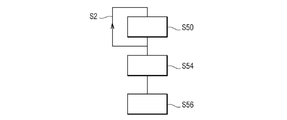
図1のイメージング装置12の作業は、ここで、試料10をイメージングするための方法を実行する一例を例示する図3のフローチャートを参照しながら説明される。
The work of the
方法は、矢印S52によって例示されるように数回反復されるイメージング工程S50と、フィルタリング工程S54と、推定工程S56とを含む。 The method comprises an imaging step S50 that is repeated several times as illustrated by arrow S52, a filtering step S54, and an estimation step S56.
イメージング工程S50中、試料10のN個の異なる観測値のセットが獲得される。
During the imaging step S50, a set of N different observations of
各イメージング工程S50は、数作業:放射する作業と、収集する作業と、画像形成の作業とを含む。 Each imaging step S50 includes several tasks: radiating, collecting, and forming an image.
放射する作業中、非集束超音波は、試料10の所与の対象の領域に放射される。
During the radiating operation, unfocused ultrasonic waves are radiated to a given target area of
非集束超音波は、開口が画定されるための波である。 Unfocused ultrasound is a wave for defining an opening.
開口は、Dと標示された具体的なサイズを有する。 The opening has a specific size labeled D.
超音波は、深さFにおける超音波と関連付けられる超音波ビームの最狭幅Wminが超音波の波長λと深さFとの積に対する開口の具体的なサイズDの比よりも大きい場合、非集束と見なされる。そのような状況は、以下のとおり数学的に表記され得る:
![]()
![]()
非集束波は、平面波または発散波を包含する。 Unfocused waves include plane waves or divergent waves.
対象の場所は、各観測値の点拡がり関数の交点によって近似される。 The location of the object is approximated by the intersection of the point spread functions of each observation.
図2の具体的な場合には、第一の列24に相当する第一の点拡がり関数PSF24および第二の列26に相当する第二の点拡がり関数PSF26が表される。
In the specific case of FIG. 2, the first point spread function PSF24 corresponding to the
点拡がり関数(PSF)は、点光源または点対象物に対するイメージングシステムの応答を説明する。PSFに対するより一般的な用語は、システムのインパルス応答であり、PSFが集束光学システムのインパルス応答である。多くの文脈におけるPSFは、非分解対象物を表す画像の拡大したぼやけとして考えら得る。 The point spread function (PSF) describes the response of the imaging system to a point light source or point object. A more general term for PSF is the impulse response of the system, where PSF is the impulse response of the focused optical system. PSF in many contexts can be thought of as an enlarged blur of an image representing a non-decomposable object.
図2の場合、PSF24とPSF26の両方の点拡がり関数の交点は、対象の領域A30である。 In the case of FIG. 2, the intersection of the point spread functions of both PSF24 and PSF26 is the target region A30.
例示の便宜上、各点拡がり関数が対象の場所A30の外側の血液領域と、対象の場所A30内の血液領域とを含むことが想定される。 For convenience of illustration, it is assumed that each point spread function includes a blood region outside the target location A30 and a blood region within the target location A30.
より正確には、第一の点拡がり関数PSF24は、第一の血液領域A32を網羅し、第二の点拡がり関数PSF26は、第二の血液領域A34を網羅し、対象の場所A30は、第三の血液領域A36を網羅する。第三の血液領域A36は、PSF24とPSF26の両方の点拡がり関数に対して共通している。 More precisely, the first point spread function PSF24 covers the first blood region A32, the second point spread function PSF26 covers the second blood region A34, and the target location A30 is the first. It covers the three blood regions A36. The third blood region A36 is common to both the PSF24 and PSF26 point spread functions.
放射する作業は、高いフレームレートで実行される。 The radiating work is performed at a high frame rate.
高いフレームレートは、100Hz以上のペースによる放射に相当する。 A high frame rate corresponds to radiation at a pace of 100 Hz or higher.
換言すると、非集束超音波は、時間間隔中に放射され、時間間隔内の非集束超音波の数の割合は、毎秒100非集束超音波以上である。 In other words, the unfocused ultrasound is radiated during the time interval, and the percentage of the number of unfocused ultrasound within the time interval is greater than or equal to 100 unfocused ultrasound per second.
もう一つの実施態様によると、フレームレートは、500Hz以上のペースによる放射に相当する。 According to another embodiment, the frame rate corresponds to radiation at a pace of 500 Hz or higher.
換言すると、非集束超音波は、時間間隔中に放射され、時間間隔内の非集束超音波の数の割合は、毎秒500非集束超音波以上である。 In other words, the unfocused ultrasound is radiated during the time interval, and the percentage of the number of unfocused ultrasound within the time interval is greater than or equal to 500 unfocused ultrasound per second.
収集する作業中、所与の対象の場所に属する拡散体は、放射された非集束超音波と相互作用する。特に、拡散体は、再帰反射波を放射する。 During the collecting operation, the diffuser belonging to a given target location interacts with the emitted unfocused ultrasonic waves. In particular, the diffuser emits retroreflected waves.
再帰反射波は、アレイ上に収集される。 The retroreflected waves are collected on the array.
画像形成作業中、所与の対象の場所のN個の観測値のセットは、収集された再帰反射波に基づく放射および受信データのサブセットを使用して、異なる点拡がり関数によって形成される。 During the image formation operation, a set of N observations at a given target location is formed by different point spread functions using a subset of the radiation and received data based on the retroreflected waves collected.
第一のイメージング工程の終わりに、N個の異なる観測値のセットは、このように、取得される。各観測値は、対象の場所に前記観測値の点拡がり関数による特異的な信号を関連付ける。 At the end of the first imaging step, a set of N different observations is thus obtained. Each observed value associates a specific signal by the point spread function of the observed value with the target location.
信号は、対象の場所内の血液の拡散体に対応する第一の寄与と、クラッタ寄与とを含む。 The signal includes a first contribution corresponding to a blood diffuser in the location of interest and a clutter contribution.
クラッタ寄与は、第二の寄与および第三の寄与を包含する。 Clutter contributions include second and third contributions.
第二の寄与は、固形組織に由来する。 The second contribution comes from the solid structure.
第三の寄与は、対象の場所の外側の血液に由来する。 The third contribution comes from the blood outside the site of interest.
第二の寄与および第三の寄与は、望ましくない寄与である。 The second and third contributions are undesirable contributions.
イメージング工程は、M個の時間的実行のN個の観測値セットを取得するためにM回反復される。 The imaging step is repeated M times to obtain an set of N observations of M temporal runs.
整数Mは、50以上である。 The integer M is 50 or more.
イメージング工程の終わりに、各時間的実行は、N個の異なる観測値のセットを含む。 At the end of the imaging process, each temporal run contains N different sets of observations.
フィルタリング工程中、M個の時間的実行の各観測値は、フィルタでフィルタリングされる。 During the filtering process, each observation of M temporal runs is filtered.
フィルタは、観測において所与の対象の場所の固形組織に由来する寄与を低減するフィルタである。 A filter is a filter that reduces the contribution derived from the solid structure of a given target location in an observation.
換言すると、フィルタは、組織信号を除去するフィルタである。 In other words, a filter is a filter that removes tissue signals.
第一の例によると、フィルタは、ハイパス時間フィルタである。 According to the first example, the filter is a high pass time filter.
第二の例によると、フィルタは、復調フィルタである。 According to the second example, the filter is a demodulation filter.
第三の例によると、フィルタは、Pが画像空間を表す[M,P]空間に対する特異値分解である。 According to the third example, the filter is a singular value decomposition for the [M, P] space where P represents the image space.
フィルタリング工程の終わりに、第二の寄与は、大きく低減され、望ましくないクラッタ信号が第三の寄与のみを包含すると考慮され得る。 At the end of the filtering process, the second contribution is greatly reduced and it can be considered that the unwanted clutter signal contains only the third contribution.
推定工程中、血流成分は、対象の領域の各場所ごとに推定される。 During the estimation process, blood flow components are estimated at each location in the area of interest.
推定工程は、統計解析を適用する作業と、計算する作業と、累積する作業とを含む。 The estimation process includes the work of applying statistical analysis, the work of calculating, and the work of accumulating.
各セットごとに、適用する作業は、第一の寄与と第三の寄与を区別するためにセットの各観測値に統計解析を適用することからなる。 For each set, the task of applying consists of applying a statistical analysis to each observation in the set to distinguish between the first and third contributions.
第一の寄与は、実際、セットのすべての観測値点拡がり関数の重なりによってアプローチされ得る対象の場所由来の血液信号に相当する。 The first contribution actually corresponds to a blood signal from the location of the subject that can be approached by the overlap of all observation point spread functions in the set.
換言すると、適用する作業は、各セットのN個の観測値への共通信号を強調するためにすべての観測値に統計解析を適用することからなる。 In other words, the work to apply consists of applying a statistical analysis to all the observations to emphasize the common signal to the N observations in each set.
適用する作業において、統計解析は、第一の寄与を抽出するために各セットの観測値に適用される。 In the task of applying, statistical analysis is applied to each set of observations to extract the first contribution.
一例によると、統計解析は、主成分分析である。 According to one example, the statistical analysis is a principal component analysis.
主成分分析(PCA)は、相関の可能性がある変数の観測値のセットを、主成分と呼ばれる線形に無相関の変数の値のセットに変換するために直交変換を使用する統計手順である。主成分の数は、元の変数の数以下である。この変換は、第一の主成分が可能な限り最大の分散(換言すれば、データのばらつきの可能な限り多くを占める)を有し、各続く成分が前の成分に直交するという拘束条件の下で可能な限り最高の分散を有するように定義される。結果として生じるベクトルは、無相関の直交基底セットである。PCAは、元の変数の相対的なスケーリングに対して敏感である。 Principal component analysis (PCA) is a statistical procedure that uses orthogonal transformations to transform a set of observed values of potentially correlated variables into a set of values of linearly uncorrelated variables called principal components. .. The number of principal components is less than or equal to the number of original variables. This transformation is constrained that the first principal component has the largest possible variance (in other words, it occupies as much of the variability of the data as possible) and each subsequent component is orthogonal to the previous component. Defined below to have the highest possible variance. The resulting vector is an uncorrelated set of orthogonal bases. The PCA is sensitive to the relative scaling of the original variable.
例を挙げると、最も重要な主成分は、第一の寄与に相当し、一方で、より重要でない主成分は、第三の寄与に相当する。 For example, the most important principal component corresponds to the first contribution, while the less important principal component corresponds to the third contribution.
もう一つの例によると、統計解析は、特異値分解である。 According to another example, the statistical analysis is a singular value decomposition.
線型代数学では、特異値分解(SVD)は、実行列または複素行列の分解である。それは、極分解の伸長を介した任意のm×n行列に対する半正定値正規行列(例として、正の固有値を持つ対称行列)の固有値分解の一般化である。 In linear algebra, singular value decomposition (SVD) is the decomposition of an execution column or complex matrix. It is a generalization of the eigenvalue decomposition of a semi-positive-definite normal matrix (eg, a symmetric matrix with positive eigenvalues) for any m × n matrix via the extension of the polar decomposition.
もう一つの例によると、統計解析は、独立成分分析である。 According to another example, the statistical analysis is an independent component analysis.
信号処理では、独立成分分析(ICA)は、多変量の信号を加法的な部分成分に分離するための計算の方法である。これは、部分成分が非ガウス信号であり、それらが互いに統計的に独立していると仮定することによってなされる。ICAは、ブラインド信号源分離の特殊なケースである。典型的な用途の例は、騒がしい部屋で一人の人の話を聞く際の「カクテルパーティー問題」である。 In signal processing, Independent Component Analysis (ICA) is a computational method for separating multivariate signals into additive subcomponents. This is done by assuming that the components are non-Gaussian signals and they are statistically independent of each other. ICA is a special case of blind separation. An example of a typical use is the "cocktail party problem" when listening to one person in a noisy room.
変形態様では、他の統計解析も考慮される。例を挙げると、カルフネン・ロエヴェ変換または対応分析を考慮することができる。 In the variant, other statistical analyzes are also considered. For example, the Karfunen-Loewe transformation or correspondence analysis can be considered.
各例では、統計解析は、N個の観測値で共通している血流信号を回復するために、[M,N]空間に対して実行される。 In each example, a statistical analysis is performed on the [M, N] space to recover the blood flow signal that is common to the N observations.
あるいは、または組み合わせて、統計解析は、対の観測値間の共役積を推定することを含む。これは、対の観測値間の第一の寄与の位相を再調整し、M個の時間的実行にわたって累積することを可能にする。 Alternatively, or in combination, statistical analysis involves estimating the conjugate product between a pair of observations. This allows the phase of the first contribution between the paired observations to be readjusted and accumulated over M temporal runs.
作業の終わりに、第一の寄与と第三の寄与との間を区別することが可能である。 At the end of the work, it is possible to distinguish between the first and third contributions.
計算する作業において、各セットごとに、血流信号の成分の推定値は、抽出された寄与に基づいて計算される。 In the task of calculating, for each set, estimates of the components of the blood flow signal are calculated based on the extracted contributions.
例を挙げると、計算する作業は、M個の時間的実行にわたって回復された血流信号の二乗を加算することによりエネルギーを評価することによって実行される。 For example, the task of calculation is performed by assessing the energy by adding the squares of the recovered blood flow signals over M temporal runs.
方法の効果は、理論計算によって説明され得る。 The effect of the method can be explained by theoretical calculations.
iがピクセルを指し、s1(i)が第一の血液領域A32で測定された血流に相当すると仮定すると、s2(i)は、第二の血液領域A34で測定された血流に相当し、s3(i)は、第三の血液領域A36で測定された血流に相当し、本方法でなされた作業は、相関の作業に相当する。これは、数学的に以下に相当する:
![]()
![]()
血液の場合、s1(i)とs2(i)とs3(i)との間には、相関はない、なぜならばそれらが無相関の信号だからである。これは、以下を生む:
![]()
![]()
それに反して、従来のパワードップラーによると、同じ推論は、以下を生むであろう:
![]()
![]()
![]()
および
![]()
の寄与は、本方法には存在しない。
![]()
and
![]()
Contribution does not exist in this method.
これは、重なっている点拡がり関数によって近似される対象の場所の外側の血管からの信号が本方法で低減され得ることを示す。 This indicates that the signal from the blood vessels outside the target location approximated by the overlapping point spread function can be reduced by this method.
換言すると、方法は、第二の寄与と第三の寄与の両方を除外するまたは少なくとも低減することを可能にする。 In other words, the method makes it possible to exclude or at least reduce both the second and third contributions.
これは、方法によって取得される分解能およびコントラストの観点から、画像のよりよい品質をもたらす。 This results in better quality of the image in terms of the resolution and contrast obtained by the method.
方法の効果は、実験的に示され得る。 The effect of the method can be demonstrated experimentally.
方法は、ここから、図4〜13を参照しながら例示されるように、画像をよりよく取得することを可能にする。 The method makes it possible to obtain better images from here, as illustrated with reference to FIGS. 4-13.
第一の実験に関して、図4は、先行技術によるパワードップラーイメージングを使用することによって取得された試料のマップを例示し、一方で、図5は、イメージング装置12を使用することによって取得された試料のマップを例示する。
For the first experiment, FIG. 4 illustrates a map of the sample obtained by using prior art Power Doppler imaging, while FIG. 5 shows the sample obtained by using the
図4と5のマップを比較するとき、図5ではより多くの血管が見えるように見える。これは、方法がより微小な血管へのアクセスを与えることを可能にするという事実を例示する。これは、イメージング装置12の空間分解能を意味する。
When comparing the maps of FIGS. 4 and 5, more blood vessels appear to be visible in FIG. This exemplifies the fact that the method allows access to smaller blood vessels. This means the spatial resolution of the
加えて、図4のマップ上で既に見えるより大きい血管に対してさえも、分解能は改善され、これらの血管の輪郭が図5ではより正確に画定される。 In addition, the resolution is improved even for larger vessels already visible on the map of FIG. 4, and the contours of these vessels are more accurately defined in FIG.
第二の実験に関して、図6および7は、伸長の方向に沿って伸長する線に実質的に相当する同じ対象物(血液を含む)をイメージングすることによって取得された結果を例示する。 For the second experiment, FIGS. 6 and 7 illustrate the results obtained by imaging the same object (including blood) that substantially corresponds to the line extending along the direction of extension.
図6は、三つの方法、図6の上から下に第一の方法、第二の方法および第三の方法によって取得された画像を例示する。第一の方法は、従来のパワードップラーイメージングである。第二の方法は、相関(統計解析用)を使用することによる本発明の方法であり、第三の方法は、特異値分解(統計解析用)を使用することによる本発明の方法である。各方法では、超音波プローブは、1024振動子を含む振動子の2次元アレイである。 FIG. 6 illustrates the images obtained by the three methods, the first method, the second method and the third method from top to bottom of FIG. The first method is conventional power Doppler imaging. The second method is the method of the present invention by using correlation (for statistical analysis), and the third method is the method of the present invention by using singular value decomposition (for statistical analysis). In each method, the ultrasonic probe is a two-dimensional array of oscillators, including 1024 oscillators.
図6の画像は目視ベースで比較することが難しいため、伸長の方向に垂直な方向に沿った強度の進展を評価することが提案される。この進展は、図7では対数目盛で表される。 Since the images of FIG. 6 are difficult to compare on a visual basis, it is proposed to evaluate the intensity evolution along the direction perpendicular to the direction of elongation. This progress is represented on a logarithmic scale in FIG.
曲線C1は、第一の方法に相当し、曲線C2は、第二の方法に相当し、曲線C3は、第三の方法に相当する。曲線C1と比較して、曲線C2およびC3については信号対雑音比が大きく増加するように見える。 The curve C1 corresponds to the first method, the curve C2 corresponds to the second method, and the curve C3 corresponds to the third method. Compared to the curve C1, the signal-to-noise ratio appears to increase significantly for the curves C2 and C3.
第三の実験に関して、図8および9は、伸長の方向に沿って伸長する線に実質的に相当するもう一つの同じ対象物(血液を含む)をイメージングすることによって取得された結果を例示する。 For the third experiment, FIGS. 8 and 9 illustrate the results obtained by imaging another same object (including blood) that substantially corresponds to a line extending along the direction of extension. ..
図8は、三つの方法、図8の上から下に第一の方法、第二の方法および第三の方法によって取得された画像を例示する。 FIG. 8 illustrates images obtained by three methods, from top to bottom of FIG. 8, the first method, the second method and the third method.
図8の画像は、対象物が第二および第三の方法でよりよい分解能を有することを明確に示す。 The image of FIG. 8 clearly shows that the object has better resolution in the second and third methods.
伸長の方向に垂直な方向に沿った強度の進展が確認される。そのような進展は、図9では対数目盛で表される。 An increase in strength is confirmed along the direction perpendicular to the direction of elongation. Such progress is represented in FIG. 9 on a logarithmic scale.
曲線C4は、第一の方法に相当し、曲線C5は、第二の方法に相当し、曲線C6は、第三の方法に相当する。曲線C4と比較して、曲線C5およびC6については信号対雑音比が大きく増加するように見える。 The curve C4 corresponds to the first method, the curve C5 corresponds to the second method, and the curve C6 corresponds to the third method. Compared to the curve C4, the signal-to-noise ratio appears to increase significantly for the curves C5 and C6.
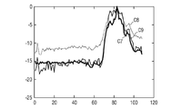
提案された方法の改善を強調するために、ハンディキャップ付きのさらなる実験が実行された。 Further experiments with a handicap were performed to highlight the improvements in the proposed method.
第四の実験に関して、図10および11は、伸長の方向に沿って伸長する線に実質的に相当する同じ対象物をイメージングすることによって取得された結果を例示する。対象物は、第二の実験のためのものと同じである。 For the fourth experiment, FIGS. 10 and 11 illustrate the results obtained by imaging the same object that substantially corresponds to a line extending along the direction of extension. The object is the same as for the second experiment.
図10は、三つの方法、図10の上から下に第一の方法、第四の方法および第五の方法によって取得された画像を例示する。念のため、第一の方法は、1024振動子を含む振動子の2次元アレイによる従来のパワードップラーイメージングである。第四の方法は、64振動子のみを含む超音波振動子の行−列アレイが使用される、相関(統計解析用)を使用することによる本発明の方法である。第五の方法は、64振動子のみを含む超音波振動子の行−列アレイが使用される、従来のパワードップラーイメージングである。 FIG. 10 illustrates images obtained by three methods, from top to bottom of FIG. 10, the first method, the fourth method and the fifth method. As a precaution, the first method is conventional power Doppler imaging with a two-dimensional array of oscillators containing 1024 oscillators. The fourth method is the method of the present invention by using a correlation (for statistical analysis) in which a row-column array of ultrasonic transducers containing only 64 transducers is used. A fifth method is conventional power Doppler imaging in which a row-column array of ultrasonic transducers containing only 64 transducers is used.
予想どおり、第五の方法で取得された画像は、第一の方法との比較によると質が落ちる。目視観測も第一の方法および第四の方法がわずかに同等なようであることを示す。 As expected, the images obtained by the fifth method are of poor quality when compared to the first method. Visual observations also show that the first and fourth methods appear to be slightly equivalent.
伸長の方向に垂直な方向に沿った強度の進展が確認される。そのような進展は、図11では対数目盛で表される。 An increase in strength is confirmed along the direction perpendicular to the direction of elongation. Such progress is represented in FIG. 11 on a logarithmic scale.
曲線C7は、第一の方法に相当し、曲線C8は、第四の方法に相当し、曲線C9は、第五の方法に相当する。曲線C8と比較して、曲線C7およびC9については信号対雑音比が大きく増加するように見える。 The curve C7 corresponds to the first method, the curve C8 corresponds to the fourth method, and the curve C9 corresponds to the fifth method. The signal-to-noise ratio appears to increase significantly for curves C7 and C9 as compared to curve C8.
これは、本発明が1024ピクセルによる従来のパワードップラーイメージングと比較して64振動子のみで同じ分解能を取得し得ることを示す。 This shows that the present invention can obtain the same resolution with only 64 oscillators as compared to conventional power Doppler imaging with 1024 pixels.
これは、現在32振動子の二つのアレイのみを備えている科学者が32振動子のそれらの二つのアレイに指令する計算機に変更を加えることによって、従来のパワードップラーイメージングによって提供される32*32=1024振動子の分解能から利益を得ることができることを示す。 This is provided by conventional power Doppler imaging by making changes to the computer that scientists currently have only two arrays of 32 oscillators commanding those two arrays of 32 oscillators. We show that we can benefit from the resolution of the 32 = 1024 oscillator.
一層よりよいことに、一部の場合、例えば、第三の実験の対象物の場合、これらの科学者は、従来のパワードップラーイメージングによって提供される32*32=1024振動子の分解能よりよい分解能から利益を得ることさえできる。 Better yet, in some cases, for example, in the case of the object of the third experiment, these scientists have better resolution than the 32 * 32 = 1024 oscillator resolution provided by conventional Power Doppler imaging. You can even benefit from it.
これは、その結果が図12および13に示される第五の実験によって例示される。 This is illustrated by the fifth experiment, the results of which are shown in FIGS. 12 and 13.
図12は、三つの方法、図12の上から下に第一の方法、第四の方法および第五の方法によって取得された画像を例示する。 FIG. 12 illustrates images obtained by three methods, from top to bottom of FIG. 12, the first method, the fourth method and the fifth method.
予想どおり、第五の方法で取得された画像は、第一の方法との比較によると質が落ちる。目視観測も、予想外に、第四の方法が第一の方法およびなおもさらに第五の方法よりもよりよい画像品質を提供するようであることを示す。 As expected, the images obtained by the fifth method are of poor quality when compared to the first method. Visual observations also unexpectedly show that the fourth method appears to provide better image quality than the first and even even fifth methods.
伸長の方向に垂直な方向に沿った強度の進展が確認される。そのような進展は、図13では対数目盛で表される。 An increase in strength is confirmed along the direction perpendicular to the direction of elongation. Such progress is represented in FIG. 13 on a logarithmic scale.
曲線C10は、第一の方法に相当し、曲線C11は、第四の方法に相当し、曲線C12は、第五の方法に相当する。曲線C10およびC11と比較するとき、曲線C12については信号対雑音比が大きく増加するように見える。 The curve C10 corresponds to the first method, the curve C11 corresponds to the fourth method, and the curve C12 corresponds to the fifth method. When compared to curves C10 and C11, the signal-to-noise ratio appears to increase significantly for curve C12.
これは、提案された方法により、64振動子を含むRCAアレイが1024振動子を含む振動子の2次元アレイよりもよりよい画像を提供することを意味する。 This means that by the proposed method, an RCA array containing 64 oscillators provides a better image than a two-dimensional array of oscillators containing 1024 oscillators.
上記の結果は、血液を伴う生体試料の場合、本発明の方法が改善された分解能を持つ画像を取得することを可能にすることを例示する。 The above results exemplify that in the case of biological samples with blood, the methods of the invention make it possible to obtain images with improved resolution.
これは、部分的に空間的に無相関化された点拡がり関数の作成による、血液の特性の賢い利用に起因する。 This is due to the wise use of blood properties by creating a point spread function that is partially spatially uncorrelated.
換言すると、本発明は、血流が場所ごとに異なるという事実に依存する。観測値に共通している寄与のみが時間的に相関がある。 In other words, the invention relies on the fact that blood flow varies from place to place. Only the contributions that are common to the observed values are temporally correlated.
本方法の他の実施態様が考慮され得る。 Other embodiments of the method may be considered.
例を挙げると、超音波振動子のアレイは、二つの優先的特異的方向に沿って受信することに電子的に集束するために適合された超音波振動子の任意のアレイである。 For example, an array of ultrasonic transducers is any array of ultrasonic transducers adapted to electronically focus on receiving along two preferential specific directions.
そのような超音波振動子は、少なくとも二つの線型または曲線型サブアレイを物理的にまたは仮想的に画定する要素の群を含み、各サブアレイが優先的方向に沿って受信することに電子的に集束するために適合される。 Such an ultrasonic transducer contains a group of elements that physically or virtually define at least two linear or curved subarrays, and each subarray is electronically focused on receiving along its preferred direction. Fitted to.
ミルズクロスアレイ、行−列アレイ、交差電極アレイもしくは下部電極直交トップ(TOBE)アレイまたはアニュラアレイは、そのような種類の超音波振動子を構成することができる具体的な例である。 Mills cross arrays, row-column arrays, cross electrode arrays or bottom electrode orthogonal top (TOBE) arrays or annular arrays are specific examples in which such types of ultrasonic transducers can be constructed.
もう一つの例によると、超音波振動子のアレイは、その要素間隔が一意の優先的方向または曲線に沿った放射中心周波数で4波長を下回る、少なくとも二つの線型または曲線型サブアレイを物理的にまたは仮想的に画定する要素の群である。 According to another example, an array of ultrasonic transducers physically contains at least two linear or curved subarrays whose element spacing is less than four wavelengths at the center of radiation frequency along a unique preferred direction or curve. Or a group of virtually demarcated elements.
例を挙げると、放射される非集束超音波の数は、観測値ごとに異なることができる。 For example, the number of unfocused ultrasound emitted can vary from observation to observation.
さらに、放射される非集束超音波の数が同じ場合でさえ、放射される非集束超音波は、観測値が同じ空間スパン時間に実行されるならば、異なる放射瞬間において放射されることができる。 Moreover, even if the number of unfocused ultrasounds emitted is the same, the unfocused ultrasounds emitted can be emitted at different emission moments if the observations are performed in the same spatial span time. ..
加えて、観測値の数は、時間的実行ごとに異なることができる。 In addition, the number of observations can vary from time to time run.
本発明は、本発明の実施態様による方法のブロック図および/またはフローチャート例示、機器(システム)および/またはコンピュータプログラム製品を参照しながら上記に説明された。ブロック図および/またはフローチャート例示の各ブロックならびにブロック図および/またはフローチャート例示のブロックの組み合わせは、コンピュータプログラム命令によって具現化されることが理解される。これらのコンピュータプログラム命令は、コンピュータおよび/または他のプログラマブルデータ処理機器のプロセッサを介して実行する命令がブロック図および/またはフローチャートブロックもしくは複数のフローチャートブロックに明記された機能/作業を具現化するための手段を作成するように、汎用コンピュータ、特殊目的用コンピュータおよび/またはマシンを産生させるための他のプログラマブルデータ処理機器のプロセッサに提供され得る。 The present invention has been described above with reference to block diagrams and / or flowchart examples of methods according to embodiments of the invention, equipment (systems) and / or computer program products. It is understood that each block of the block diagram and / or the example of the flowchart and the combination of the blocks of the block diagram and / or the example of the flowchart are embodied by computer program instructions. These computer program instructions embody the functions / tasks specified in the block diagram and / or the flow chart block or multiple flow chart blocks by the instructions executed through the processor of the computer and / or other programmable data processing equipment. It may be provided to the processors of general purpose computers, special purpose computers and / or other programmable data processing equipment for producing machines so as to create the means of.
これらのコンピュータプログラム命令は、ブロック図および/またはフローチャートブロックもしくは複数のフローチャートブロックに明記された機能/作業を具現化する命令を包含するコンピュータ読み取り可能なメモリに記憶された命令が製造品を産生させるように、コンピュータまたは他のプログラマブルデータ処理機器に特有のやり方で機能するように指示することができる、コンピュータ読み取り可能なメモリに記憶されることもできる。 These computer program instructions are manufactured by instructions stored in computer-readable memory that include instructions that embody the functions / tasks specified in the block diagram and / or the flowchart block or multiple flowchart blocks. As such, it can also be stored in computer-readable memory that can be instructed to function in a way specific to a computer or other programmable data processing device.
コンピュータプログラム命令は、一連の作業工程をコンピュータまたは他のプログラマブル機器上で実施させ、コンピュータまたは他のプログラマブル機器上で実行する命令がブロック図および/またはフローチャートブロックもしくは複数のフローチャートブロックに明記された機能/作業を具現化するための工程を提供するようにコンピュータによって具現化されるプロセスを産生させるために、コンピュータまたは他のプログラマブルデータ処理機器に取り込まれることもできる。それゆえに、本発明は、ハードウェアおよび/またはソフトウェア(ファームウェア、常駐ソフトウェア、マイクロコードなどを包含する)に具体化され得る。さらに、本発明の実施態様は、命令実行システムによる使用のためにまたはそれと接続して媒体に具体化されたコンピュータ使用可能なまたはコンピュータ読み取り可能なプログラムコードを有する、コンピュータ使用可能なまたはコンピュータ読み取り可能な非一時的記憶媒体上のコンピュータプログラム製品の形態を取ることができる。 A computer program instruction is a function in which a series of work processes is executed on a computer or other programmable device, and instructions to be executed on the computer or other programmable device are specified in a block diagram and / or a flowchart block or a plurality of flowchart blocks. It can also be incorporated into a computer or other programmable data processing device to produce a process that is embodied by a computer to provide a process for embodying the work. Therefore, the present invention can be embodied in hardware and / or software (including firmware, resident software, microcode, etc.). Further, embodiments of the present invention have computer-enabled or computer-readable program code embodied in a medium for use by or in connection with an instruction execution system, computer-enabled or computer-readable. It can take the form of a computer program product on a non-temporary storage medium.
コンピュータ使用可能なまたはコンピュータ読み取り可能な媒体は、例として、電子、光学、電磁、赤外線もしくは半導体システム、機器または装置であることができるが、限定されるわけではない。コンピュータ読み取り可能な媒体のより具体的な例(非網羅的リスト)は、以下を包含するであろう:一つ以上の電線を有する電気接続、ポータブルコンピュータディスケット、ランダムアクセスメモリ(RAM)、読み出し専用メモリ(ROM)、消去可能プログラマブル読み出し専用メモリ(EPROMまたはフラッシュメモリ)、光ファイバーおよびポータブルコンパクトディスク読み出し専用メモリ(CD−ROM)。 Computer-enabled or computer-readable media can, by example, be electronic, optical, electromagnetic, infrared or semiconductor systems, devices or devices, but are not limited. More specific examples (non-exhaustive lists) of computer-readable media would include: electrical connections with one or more wires, portable computer diskettes, random access memory (RAM), read-only. Memory (ROM), erasable programmable read-only memory (EPROM or flash memory), optical fiber and portable compact disk read-only memory (CD-ROM).
先に本明細書で考慮された実施態様および代替実施態様は、本発明のさらなる実施態様を生成するために組み合わされ得る。 The embodiments and alternative embodiments discussed herein above can be combined to generate further embodiments of the invention.
Claims (15)
−以下の作業:
−時間間隔内の非集束超音波の数の割合が毎秒100非集束超音波以上であって、対象の領域内の非集束超音波が時間間隔中に放射される放射作業と、
−所与の対象の領域の拡散体からの再帰反射波が収集される収集作業と、
−各観測値が信号を対象の領域の各場所と関連付ける異なるかつ部分的に空間的に無相関化された点拡がり関数によって特徴付けられ、信号が場所内の血管の拡散体に対応する第一の寄与、組織拡散体に対応する第二の寄与および場所の外側の血液拡散体と関連付けられる血液信号に対応する第三の寄与を含み、第二および第三の寄与が望ましくない、対象の領域の異なる観測値が収集された再帰反射波に基づいて生成される画像形成作業とを含み、
イメージング工程が対象の領域のM個の時間的実行の観測値セットを取得するためにM回反復され、Mが10以上であるイメージング工程と、
−観測値セットの各々の第二の寄与を低減するためのフィルタリング工程と、
−対象の領域の各場所ごとに血流信号が推定される推定工程とを含み、推定工程が以下の作業:
−第一の寄与および第三の寄与を区別するために各セットの観測値に統計解析を適用することと、
−第一の寄与に基づいて血流信号の成分の推定値を計算することと
を含む方法。 A method for imaging a biological sample (10), wherein the sample (10) contains blood (14) and solid tissue (16) containing a diffuser, and the method is:
-The following work:
-Radiation work in which the ratio of the number of unfocused ultrasonic waves in the time interval is 100 or more unfocused ultrasonic waves per second and the unfocused ultrasonic waves in the target area are radiated during the time interval.
-A collection task in which retroreflected waves from a diffuser in a given area of interest are collected, and
− Each observation is characterized by a different and partially spatially uncorrelated point spread function that associates the signal with each location in the region of interest, and the signal corresponds to a diffuser of blood vessels within the location. Contribution of interest, a second contribution corresponding to the tissue spreader and a third contribution corresponding to the blood signal associated with the blood spreader outside the location, where the second and third contributions are undesirable. Including image formation work generated based on the retroreflected waves collected from different observations of
An imaging step in which the imaging step is repeated M times to obtain a set of observations of M temporal runs of the region of interest, with an M of 10 or greater.
-A filtering step to reduce each second contribution of the observed set, and
-Including the estimation process in which the blood flow signal is estimated for each location in the target area, the estimation process is as follows:
-Applying statistical analysis to each set of observations to distinguish between the first and third contributions,
-A method that includes calculating an estimate of the components of the blood flow signal based on the first contribution.
−時間間隔内の非集束超音波の数の割合が毎秒100非集束超音波以上であって、対象の領域内の非集束超音波が時間間隔中に放射される放射作業と、
−所与の対象の領域の拡散体からの再帰反射波が収集される収集作業と、
−各観測値が信号を対象の領域の各場所と関連付ける異なるかつ部分的に空間的に無相関化された点拡がり関数によって特徴付けられ、信号が場所内の血管の拡散体に対応する第一の寄与、組織拡散体に対応する第二の寄与および場所の外側の血液拡散体と関連付けられる血液信号に対応する第三の寄与を含み、第二および第三の寄与が望ましくない、対象の領域の異なる観測値が収集された再帰反射波に基づいて生成される画像形成作業とを含むイメージング工程を実行するために適合された超音波イメージャ(22)を含み、
イメージング工程が対象の領域のM個の時間的実行の観測値セットを取得するためにM回反復され、Mが10以上であり、
イメージング装置(12)が:
−観測値セットの各々の第二の寄与を低減するためのフィルタリング工程と、
−対象の領域の各場所ごとに血流信号が推定される推定工程とを実行するために適合された計算機(23)をさらに含み、推定工程が以下の作業:
−第一の寄与および第三の寄与を区別するために各観測値セットに統計解析を適用することと、
−第一の寄与に基づいて血流信号の成分の推定値を計算することと
を含むイメージング装置。 An imaging device (12) for imaging a biological sample (10), wherein the sample (10) contains blood (14) and solid tissue (16) containing a diffuser, and the imaging device (12) performs the following operations. :
-Radiation work in which the ratio of the number of unfocused ultrasonic waves in the time interval is 100 or more unfocused ultrasonic waves per second and the unfocused ultrasonic waves in the target area are radiated during the time interval.
-A collection task in which retroreflected waves from a diffuser in a given area of interest are collected, and
− Each observation is characterized by a different and partially spatially uncorrelated point spread function that associates the signal with each location in the region of interest, and the signal corresponds to a diffuser of blood vessels within the location. Contribution of interest, a second contribution corresponding to the tissue spreader and a third contribution corresponding to the blood signal associated with the blood spreader outside the location, where the second and third contributions are undesirable. Includes an ultrasonic imager (22) adapted to perform imaging steps, including image formation work in which different observations of the blood are generated based on the collected retroreflected waves.
The imaging process is repeated M times to obtain a set of observations of M temporal runs of the region of interest, with M greater than or equal to 10.
The imaging device (12) is:
-A filtering step to reduce each second contribution of the observed set, and
-Including a computer (23) adapted to perform an estimation process in which a blood flow signal is estimated for each location in the area of interest, the estimation process is:
-Applying statistical analysis to each set of observations to distinguish between the first and third contributions,
-An imaging device that includes calculating estimates of the components of a blood flow signal based on the first contribution.
Applications Claiming Priority (3)
| Application Number | Priority Date | Filing Date | Title |
|---|---|---|---|
| EP16306185.6 | 2016-09-16 | ||
| EP16306185 | 2016-09-16 | ||
| PCT/EP2017/073271 WO2018050817A1 (en) | 2016-09-16 | 2017-09-15 | Method for imaging a sample with blood and associated devices |
Publications (3)
| Publication Number | Publication Date |
|---|---|
| JP2019528895A JP2019528895A (en) | 2019-10-17 |
| JP2019528895A5 JP2019528895A5 (en) | 2020-08-06 |
| JP6912561B2 true JP6912561B2 (en) | 2021-08-04 |
Family
ID=57189984
Family Applications (1)
| Application Number | Title | Priority Date | Filing Date |
|---|---|---|---|
| JP2019514807A Active JP6912561B2 (en) | 2016-09-16 | 2017-09-15 | Methods and related equipment for imaging samples with blood |
Country Status (6)
| Country | Link |
|---|---|
| US (1) | US11617560B2 (en) |
| EP (1) | EP3512431A1 (en) |
| JP (1) | JP6912561B2 (en) |
| CN (1) | CN110072462B (en) |
| IL (1) | IL265223B2 (en) |
| WO (1) | WO2018050817A1 (en) |
Families Citing this family (3)
| Publication number | Priority date | Publication date | Assignee | Title |
|---|---|---|---|---|
| CN111281428B (en) * | 2020-02-12 | 2021-08-06 | 深圳大学 | Ultrasonic probe for monitoring hemodynamic parameters |
| KR102375825B1 (en) * | 2021-04-28 | 2022-03-17 | 주식회사 엣지케어 | Ultrasound imaging device and ultrasound imaging system including the same |
| CN113367675A (en) * | 2021-05-21 | 2021-09-10 | 天津大学 | Blood flow dynamic detection method, system and medium based on laser speckle imaging |
Family Cites Families (41)
| Publication number | Priority date | Publication date | Assignee | Title |
|---|---|---|---|---|
| JPH03176036A (en) * | 1989-12-05 | 1991-07-31 | Aloka Co Ltd | Ultrasonic doppler diagnostic apparatus |
| JPH03215250A (en) * | 1990-01-19 | 1991-09-20 | Toshiba Corp | Ultrasonic probe and ultrasonic diagnostic apparatus using the same |
| JPH03231650A (en) * | 1990-02-07 | 1991-10-15 | Toshiba Corp | Ultrasonic diagnostic apparatus |
| US5245587A (en) * | 1990-12-14 | 1993-09-14 | Hutson William H | Multi-dimensional signal processing and display |
| JPH10314171A (en) * | 1997-05-15 | 1998-12-02 | Toshiba Iyou Syst Eng Kk | Ultrasonic diagnostic device |
| US6579238B1 (en) * | 2000-04-24 | 2003-06-17 | Acuson Corporation | Medical ultrasonic imaging system with adaptive multi-dimensional back-end mapping |
| US6318179B1 (en) * | 2000-06-20 | 2001-11-20 | Ge Medical Systems Global Technology Company, Llc | Ultrasound based quantitative motion measurement using speckle size estimation |
| US6468216B1 (en) * | 2000-08-24 | 2002-10-22 | Kininklijke Philips Electronics N.V. | Ultrasonic diagnostic imaging of the coronary arteries |
| EP1300690B1 (en) * | 2001-10-02 | 2009-07-29 | B-K Medical A/S | Apparatus and method for velocity estimation in synthetic aperture imaging |
| US20060042389A1 (en) * | 2002-10-09 | 2006-03-02 | Matsushita Electric Industrial Co., Ltd. | Ultrasonic diagnosing device |
| JP2004129797A (en) * | 2002-10-09 | 2004-04-30 | Matsushita Electric Ind Co Ltd | Ultrasonic diagnostic equipment |
| JP4244300B2 (en) * | 2003-03-24 | 2009-03-25 | 富士フイルム株式会社 | Ultrasonic transceiver |
| TW200618774A (en) * | 2004-12-01 | 2006-06-16 | Yio-Wha Shau | Real time inspection system and inspection method for micro-circulation |
| US8162837B2 (en) * | 2005-06-13 | 2012-04-24 | Spentech, Inc. | Medical doppler ultrasound system for locating and tracking blood flow |
| US7720268B2 (en) * | 2005-07-15 | 2010-05-18 | Siemens Corporation | System and method for ultrasound specific segmentation using speckle distributions |
| US8626263B2 (en) * | 2006-04-13 | 2014-01-07 | General Electric Company | Methods and apparatus for relative perfusion and/or viability |
| US8306293B2 (en) * | 2008-05-15 | 2012-11-06 | University Of Virginia Patent Foundation | Reduction of echo decorrelation facilitating motion estimation |
| DK2303131T3 (en) * | 2008-06-26 | 2015-05-04 | Verasonics Inc | Quantitative Doppler flow imaging with high frame rate using unfocused transmission rays |
| US10172527B2 (en) * | 2009-07-31 | 2019-01-08 | Supersonic Imagine | Method and apparatus for measuring a physical parameter in mammal soft tissues by propagating shear waves |
| ITGE20090070A1 (en) * | 2009-08-31 | 2011-03-01 | Esaote Spa | METHOD AND DEVICE FOR DETECTION AND VISUALIZATION OF HEMODYNAMIC INFORMATION IN PARTICULAR OF THE EMATIC FLOW IN THE VEINS, VIA ULTRASONI |
| JP5499939B2 (en) | 2010-06-25 | 2014-05-21 | セイコーエプソン株式会社 | Measuring device, biopsy device, flow velocity measuring method, and pressure measuring method |
| FR2969350B1 (en) | 2010-12-16 | 2013-01-11 | Centre Nat Rech Scient | METHOD AND DEVICE FOR SOUND IMAGING. |
| WO2012142455A2 (en) * | 2011-04-14 | 2012-10-18 | Regents Of The University Of Minnesota | Vascular characterization using ultrasound imaging |
| US9002080B2 (en) * | 2011-10-12 | 2015-04-07 | University Of Virginia Patent Foundation | Singular value filter for imaging or detection |
| JP2014023934A (en) * | 2012-07-27 | 2014-02-06 | Samsung Electronics Co Ltd | Image processing module and image generation method |
| GB201216455D0 (en) * | 2012-09-14 | 2012-10-31 | Isis Innovation | Passive ultrasound imaging with sparse transducer arrays |
| WO2014138555A1 (en) * | 2013-03-07 | 2014-09-12 | Bernhard Sturm | Multimodal segmentation in intravascular images |
| WO2014192751A1 (en) * | 2013-05-27 | 2014-12-04 | 株式会社東芝 | Image processing device and image processing method |
| US20160084948A1 (en) | 2013-05-28 | 2016-03-24 | Duke University | Systems, methods and computer program products for doppler spatial coherence imaging |
| FR3008802B1 (en) * | 2013-07-19 | 2015-08-14 | Centre Nat Rech Scient | METHOD AND DEVICE FOR CARTOGRAPHY OF FIBROUS MEDIA |
| KR20150118731A (en) * | 2014-04-15 | 2015-10-23 | 삼성전자주식회사 | Ultrasound imaging apparatus and control method for the same |
| US10624612B2 (en) * | 2014-06-05 | 2020-04-21 | Chikayoshi Sumi | Beamforming method, measurement and imaging instruments, and communication instruments |
| JP6282942B2 (en) * | 2014-06-18 | 2018-02-21 | キヤノンメディカルシステムズ株式会社 | Ultrasonic diagnostic apparatus, image processing apparatus, and image processing program |
| EP2963672A1 (en) * | 2014-06-30 | 2016-01-06 | FEI Company | Computational scanning microscopy with improved resolution |
| FR3026493B1 (en) | 2014-09-26 | 2021-02-12 | Centre Nat Rech Scient | ACOUSTIC IMAGING PROCESS AND DEVICE. |
| US10548571B1 (en) * | 2014-11-21 | 2020-02-04 | Ultrasee Corp | Fast 2D blood flow velocity imaging |
| KR20160087221A (en) * | 2015-01-13 | 2016-07-21 | 삼성메디슨 주식회사 | Ultrasonic diagnostic apparatus and operating method for the same |
| US9855022B2 (en) * | 2015-01-19 | 2018-01-02 | B-K Medical Aps | 3-D flow estimation using row-column addressed transducer arrays |
| CA2981305A1 (en) * | 2015-04-01 | 2016-10-06 | Verasonics, Inc. | Method and system for coded excitation imaging by impulse response estimation and retrospective acquisition |
| CN105726000B (en) * | 2016-01-29 | 2019-03-22 | 北京工业大学 | A kind of device of the cardiovascular functional parameter based on blood pressure of four limbs pulse |
| US11298110B2 (en) * | 2016-02-26 | 2022-04-12 | Omar MANSOUR | Doppler measurement system and method |
-
2017
- 2017-09-15 JP JP2019514807A patent/JP6912561B2/en active Active
- 2017-09-15 CN CN201780057135.3A patent/CN110072462B/en active Active
- 2017-09-15 WO PCT/EP2017/073271 patent/WO2018050817A1/en unknown
- 2017-09-15 US US16/330,948 patent/US11617560B2/en active Active
- 2017-09-15 EP EP17771395.5A patent/EP3512431A1/en active Pending
-
2019
- 2019-03-07 IL IL265223A patent/IL265223B2/en unknown
Also Published As
| Publication number | Publication date |
|---|---|
| CN110072462B (en) | 2022-05-24 |
| IL265223B (en) | 2022-11-01 |
| US20190247011A1 (en) | 2019-08-15 |
| EP3512431A1 (en) | 2019-07-24 |
| CN110072462A (en) | 2019-07-30 |
| IL265223A (en) | 2019-05-30 |
| WO2018050817A1 (en) | 2018-03-22 |
| US11617560B2 (en) | 2023-04-04 |
| IL265223B2 (en) | 2023-03-01 |
| JP2019528895A (en) | 2019-10-17 |
Similar Documents
| Publication | Publication Date | Title |
|---|---|---|
| JP6932192B2 (en) | Methods and systems for filtering ultrasound image clutter | |
| Jensen | Medical ultrasound imaging | |
| CN105793729B (en) | It is formed and/or is rebuild using the ultrasonoscopy of multi-frequency waveform | |
| JP5627890B2 (en) | Dual path processing for optimal speckle tracking | |
| KR102051293B1 (en) | Classification preprocessing in medical ultrasound shear wave imaging | |
| JP6912561B2 (en) | Methods and related equipment for imaging samples with blood | |
| CN102209495A (en) | Ultrasonic lesion identification using temporal parametric contrast images | |
| KR20180013956A (en) | Method, system and computer program product for single tracking position shear wave elastic imaging | |
| US20220292637A1 (en) | Methods for High Spatial and Temporal Resolution Ultrasound Imaging of Microvessels | |
| KR101610874B1 (en) | Module for Processing Ultrasonic Signal Based on Spatial Coherence and Method for Processing Ultrasonic Signal | |
| CN113662586A (en) | Cross-correlation noise reduction method for ultrafast ultrasonic micro-blood flow imaging | |
| WO2017051903A1 (en) | Ultrasonic diagnostic system and ultrasonic diagnostic method | |
| WO2023025165A1 (en) | Focused ultrasound treatment system based on ultrasound imaging | |
| WO2020231954A1 (en) | Methods, systems, and computer readable media for generating images of microvasculature using ultrasound | |
| Yoshikawa et al. | Dynamic and precise visualization of contrast agent in blood vessels with motion correction | |
| WO2018230409A1 (en) | Information processing device, information processing method, and program | |
| JP2022500136A (en) | Systems and methods for tracking tools in ultrasound images | |
| CN112672696A (en) | System and method for tracking tools in ultrasound images | |
| Cheung et al. | Adaptive clutter filter design for micro-ultrasound color flow imaging of small blood vessels | |
| Yang et al. | High frequency ultrasound speckle flow imaging-comparison with Doppler optical coherence tomography (DOCT) | |
| US20240032892A1 (en) | Boundary detection in ultrasound data | |
| Corazza et al. | Adaptive beamforming combined with decision theory-based detection for ultrasound localization microscopy | |
| Hemmsen et al. | Preliminary In-Vivo evaluation of Synthetic Aperture Sequential Beamformation using a multielement convex array | |
| Jafarzadeh et al. | Spatially segmented SVD clutter filtering in cardiac blood flow imaging with diverging waves | |
| JP2023531982A (en) | Systems and methods for identifying blood vessels from ultrasound data |
Legal Events
| Date | Code | Title | Description |
|---|---|---|---|
| A524 | Written submission of copy of amendment under article 19 pct |
Free format text: JAPANESE INTERMEDIATE CODE: A524 Effective date: 20200623 |
|
| A621 | Written request for application examination |
Free format text: JAPANESE INTERMEDIATE CODE: A621 Effective date: 20200623 |
|
| A977 | Report on retrieval |
Free format text: JAPANESE INTERMEDIATE CODE: A971007 Effective date: 20210526 |
|
| TRDD | Decision of grant or rejection written | ||
| A01 | Written decision to grant a patent or to grant a registration (utility model) |
Free format text: JAPANESE INTERMEDIATE CODE: A01 Effective date: 20210622 |
|
| A61 | First payment of annual fees (during grant procedure) |
Free format text: JAPANESE INTERMEDIATE CODE: A61 Effective date: 20210708 |
|
| R150 | Certificate of patent or registration of utility model |
Ref document number: 6912561 Country of ref document: JP Free format text: JAPANESE INTERMEDIATE CODE: R150 |
|
| S111 | Request for change of ownership or part of ownership |
Free format text: JAPANESE INTERMEDIATE CODE: R313115 |
|
| R350 | Written notification of registration of transfer |
Free format text: JAPANESE INTERMEDIATE CODE: R350 |
|
| S633 | Written request for registration of reclamation of name |
Free format text: JAPANESE INTERMEDIATE CODE: R313633 |
|
| R350 | Written notification of registration of transfer |
Free format text: JAPANESE INTERMEDIATE CODE: R350 |