EP3149383B1 - Plug connector for fluid lines, comprising an inner adapter sleeve - Google Patents
Plug connector for fluid lines, comprising an inner adapter sleeve Download PDFInfo
- Publication number
- EP3149383B1 EP3149383B1 EP15726599.2A EP15726599A EP3149383B1 EP 3149383 B1 EP3149383 B1 EP 3149383B1 EP 15726599 A EP15726599 A EP 15726599A EP 3149383 B1 EP3149383 B1 EP 3149383B1
- Authority
- EP
- European Patent Office
- Prior art keywords
- latching
- connector
- sleeve
- adapter sleeve
- section
- Prior art date
- Legal status (The legal status is an assumption and is not a legal conclusion. Google has not performed a legal analysis and makes no representation as to the accuracy of the status listed.)
- Active
Links
- 239000012530 fluid Substances 0.000 title claims description 16
- 230000013011 mating Effects 0.000 claims description 58
- 238000003780 insertion Methods 0.000 claims description 53
- 230000037431 insertion Effects 0.000 claims description 52
- 210000002105 tongue Anatomy 0.000 claims description 15
- 238000006073 displacement reaction Methods 0.000 claims description 11
- 230000008878 coupling Effects 0.000 claims description 7
- 238000010168 coupling process Methods 0.000 claims description 7
- 238000005859 coupling reaction Methods 0.000 claims description 7
- 230000000903 blocking effect Effects 0.000 claims description 4
- 238000007789 sealing Methods 0.000 claims description 4
- 230000007704 transition Effects 0.000 claims description 3
- 230000002093 peripheral effect Effects 0.000 description 29
- 238000013461 design Methods 0.000 description 14
- 239000000463 material Substances 0.000 description 4
- 230000015572 biosynthetic process Effects 0.000 description 3
- 230000001154 acute effect Effects 0.000 description 2
- 238000013459 approach Methods 0.000 description 2
- 238000000034 method Methods 0.000 description 2
- 230000000007 visual effect Effects 0.000 description 2
- 238000010521 absorption reaction Methods 0.000 description 1
- 230000006978 adaptation Effects 0.000 description 1
- 239000000654 additive Substances 0.000 description 1
- 230000004323 axial length Effects 0.000 description 1
- 230000005540 biological transmission Effects 0.000 description 1
- 238000010276 construction Methods 0.000 description 1
- 238000001816 cooling Methods 0.000 description 1
- 239000000498 cooling water Substances 0.000 description 1
- 230000006735 deficit Effects 0.000 description 1
- 230000001419 dependent effect Effects 0.000 description 1
- 238000011161 development Methods 0.000 description 1
- 230000018109 developmental process Effects 0.000 description 1
- 230000000694 effects Effects 0.000 description 1
- 230000005489 elastic deformation Effects 0.000 description 1
- 239000000446 fuel Substances 0.000 description 1
- 230000001771 impaired effect Effects 0.000 description 1
- 238000009434 installation Methods 0.000 description 1
- 238000004519 manufacturing process Methods 0.000 description 1
- 239000002184 metal Substances 0.000 description 1
- 238000009423 ventilation Methods 0.000 description 1
Images


Classifications
-
- F—MECHANICAL ENGINEERING; LIGHTING; HEATING; WEAPONS; BLASTING
- F16—ENGINEERING ELEMENTS AND UNITS; GENERAL MEASURES FOR PRODUCING AND MAINTAINING EFFECTIVE FUNCTIONING OF MACHINES OR INSTALLATIONS; THERMAL INSULATION IN GENERAL
- F16L—PIPES; JOINTS OR FITTINGS FOR PIPES; SUPPORTS FOR PIPES, CABLES OR PROTECTIVE TUBING; MEANS FOR THERMAL INSULATION IN GENERAL
- F16L37/00—Couplings of the quick-acting type
- F16L37/24—Couplings of the quick-acting type in which the connection is made by inserting one member axially into the other and rotating it to a limited extent, e.g. with bayonet action
- F16L37/244—Couplings of the quick-acting type in which the connection is made by inserting one member axially into the other and rotating it to a limited extent, e.g. with bayonet action the coupling being co-axial with the pipe
- F16L37/248—Bayonet-type couplings
-
- F—MECHANICAL ENGINEERING; LIGHTING; HEATING; WEAPONS; BLASTING
- F16—ENGINEERING ELEMENTS AND UNITS; GENERAL MEASURES FOR PRODUCING AND MAINTAINING EFFECTIVE FUNCTIONING OF MACHINES OR INSTALLATIONS; THERMAL INSULATION IN GENERAL
- F16L—PIPES; JOINTS OR FITTINGS FOR PIPES; SUPPORTS FOR PIPES, CABLES OR PROTECTIVE TUBING; MEANS FOR THERMAL INSULATION IN GENERAL
- F16L37/00—Couplings of the quick-acting type
- F16L37/08—Couplings of the quick-acting type in which the connection between abutting or axially overlapping ends is maintained by locking members
- F16L37/084—Couplings of the quick-acting type in which the connection between abutting or axially overlapping ends is maintained by locking members combined with automatic locking
- F16L37/098—Couplings of the quick-acting type in which the connection between abutting or axially overlapping ends is maintained by locking members combined with automatic locking by means of flexible hooks
- F16L37/0985—Couplings of the quick-acting type in which the connection between abutting or axially overlapping ends is maintained by locking members combined with automatic locking by means of flexible hooks the flexible hook extending radially inwardly from an outer part and engaging a bead, recess or the like on an inner part
-
- F—MECHANICAL ENGINEERING; LIGHTING; HEATING; WEAPONS; BLASTING
- F16—ENGINEERING ELEMENTS AND UNITS; GENERAL MEASURES FOR PRODUCING AND MAINTAINING EFFECTIVE FUNCTIONING OF MACHINES OR INSTALLATIONS; THERMAL INSULATION IN GENERAL
- F16L—PIPES; JOINTS OR FITTINGS FOR PIPES; SUPPORTS FOR PIPES, CABLES OR PROTECTIVE TUBING; MEANS FOR THERMAL INSULATION IN GENERAL
- F16L37/00—Couplings of the quick-acting type
- F16L37/08—Couplings of the quick-acting type in which the connection between abutting or axially overlapping ends is maintained by locking members
- F16L37/084—Couplings of the quick-acting type in which the connection between abutting or axially overlapping ends is maintained by locking members combined with automatic locking
Definitions
- the present invention relates to a connector according to the preamble of claim 1.
- a connector of the prior art is from DE 10 2011 084 988 known.
- the form-fitting means are formed on the outside of the free end of the latching arms.
- the latching cams are also arranged on the underside of these latching arms, with the latching cams being located within the socket section.
- this arrangement and design of the form-fitting elements and the latching cams necessitate a relatively long construction of the sleeve section and, moreover, there is a relatively large cutout in the wall of the sleeve section, so that the latching arms are unprotected and dirt can also easily penetrate into the sleeve section.
- the connecting unit made up of plug connector and mating plug connector which is known from this publication, has additional holding elements in order to ensure protection against rotation.
- a plug-in coupling has a receiving part and a securing part.
- a plug-in part can be connected to the receiving part by means of a rear locking piece of the securing part.
- the securing part has an annular sleeve on which the rear locking pieces and a blocking piece are attached via a respective spring bar.
- the blocking pieces are after Insertion of the male part is blocked by the male part radially inward so that it faces an abutment wall with an abutment wall.
- each rear locking piece of a cover wall is covered, so that access to each blocking piece from the outside is prevented.
- the spring bars for holding the rear latching pieces for holding the plug-in part are angled to a longitudinal center axis of the receiving part or the securing part.
- the invention is based on the object, starting from a connector of the type mentioned, to provide a connector which, regardless of the housing material and even in cramped installation conditions, ensures full elasticity and perfect functioning of the locking means and has a compact design and a allows a protected arrangement of the locking arms.
- the latching means are not part of the housing, but the latching means are formed on the separate part of the adapter sleeve, which is inserted into the housing. This means that different materials can be used for the housing and the adapter sleeve.
- the adapter sleeve sits in the housing in a manner that is essentially protected around the circumference, so that its function cannot be significantly impaired by other adjacent housings.
- the form-fitting elements in the inserted state engage in recesses in the peripheral wall of the sleeve section in a form-fitting manner with a locking effect makes it possible for the adapter sleeve to be designed to be relatively short and compact.
- the positive-locking elements according to the invention ensure both an axial fixation and, in particular, a circumferential fixation of the adapter sleeve in the socket section. Due to the form fit in the axial direction, the adapter sleeve cannot be loosened by tensile stress and twisting of the adapter sleeve is also avoided by a form fit according to the invention in the circumferential direction.
- the adapter sleeve has an annular collar running on the circumference of its through-opening at its rear opening edge, viewed in the direction of insertion, which is arranged outside the sleeve section when the adapter sleeve is inserted, with the first locking cams likewise running outside the sleeve section.
- latching arms offset by 180° from one another are formed on the adapter sleeve, and there are actuating projections protruding radially outwards in relation to the longitudinal center axis at the free ends of the latching arms.
- This design enables the plugged-in connector to be released by means of a release tool, in particular a fork-shaped release tool, with the fork prongs being inserted into the insertion opening and the latching arms being able to be brought out of engagement with their latching cams from a latching groove of the mating connector by moving the release tool perpendicularly to the longitudinal center axis.
- a release tool in particular a fork-shaped release tool
- the annular collar is separated from the adapter sleeve by circumferential gap sections between its latching arms, and the annular collar surrounds the latching arms in the area of the first latching cams on the outside and is connected to them in the area of the latching cams and the annular collar in the middle between the Locking arms has deformation sections which are deformable under a force directed radially to the longitudinal center axis in such a way that a radially outward spreading of the locking arms is generated in such a way that the first locking cams assume their release position. This enables the plugged-in mating connector to be detached by hand.
- the thickness of the latching arms is less than the wall thickness of the adapter sleeve, so that a step surface running radially in the direction of the longitudinal central axis is formed between an outer circumference of the wall of the adapter sleeve and the latching arms.
- the radial height of the step surface and the length of the locking arms within the sleeve section are dimensioned in such a way that a radially outward spring deflection of the locking cams is given such that a radial distance between the radially outwardly spread locking cams is greater than or equal to an inner diameter of the adapter sleeve and /or is greater than/equal to the outer diameter of the plug shank of the mating connector.
- the outside diameter of the annular collar is equal to the outside diameter of the socket section.
- the radial spacing of the angled extensions on their outer surfaces is equal to the outer diameter of the socket section.
- an outer diameter of the annular collar in the area of the locking cams is equal to the outer diameter of the socket section.
- the latching arms in the area of the latching cams can be bent outwards by the plugged-in connector, so that the latching arms with the angled extensions or the annular collar protrude radially against the outer circumference of the socket section during the plugging process in the region of the latching cams, as a result An insertion control is given, since they only spring back after snapping into the locking groove of the plug shank of the mating connector, thus indicating that the insertion process is complete.
- a peripheral seal is arranged in the insertion direction in front of the adapter sleeve in the through opening of the sleeve section for sealing a peripheral gap between an inner wall of the sleeve section and the plug shank of a mating connector. It is advantageous here if an annular shoulder is formed in the socket section at the transition from the diameter-enlarged section of the socket section to the through-channel for the peripheral seal to rest and the peripheral seal is chambered between the annular shoulder and an end face of the adapter sleeve.
- This arrangement of the peripheral seal according to the invention makes it possible that undercuts do not have to be formed either in the connector or in the mating connector in order to achieve chambering of the peripheral seal.
- the peripheral seal sits protected inside the socket section.
- the connecting section of the housing opposite the socket section is designed as a connecting pin, the connecting pin having a peripheral seal in the area of its free end in a circumferential groove and in the area opposite the free end of the connecting pin there are several seals in the direction of the free end extending, parallel to the longitudinal center axis of the connecting pin extending latching webs are arranged, which are distributed on the circumference of the connecting pin spaced evenly.
- latching webs there are preferably two diametrically opposite latching webs.
- the locking webs have locking projections which are directed radially inwards in relation to the longitudinal center axis of the connecting pin.
- a guide gap is formed between the latching webs and the connecting pin, into which a connecting sleeve of a connecting connector can be pushed, which has an inner through-bore in which the connecting pin is guided, and the free end of the connecting sleeve on its outer circumference there is a radially outwardly projecting ring extension in relation to the longitudinal central axis, which has ramps corresponding to the locking projections of the locking webs, so that it is possible to push on the connecting sleeve, with the locking webs being spread radially outwards.
- This inventive design of the connecting pin and the connecting sleeve allows an axial relative displacement of these parts to each other in the connected state. This design significantly increases the crash safety of a connector according to the invention, because this design according to the invention allows, for example, a length compensation of a maximum of 50 mm to 60 mm, preferably 20 mm.
- the present invention relates to a plug-in coupling consisting of a plug connector according to one of the aforementioned embodiments and a mating connector for plugging into the plug connector according to the invention, the mating connector having a plug shank and a plug in the direction of insertion having locking groove formed behind the plug shank.
- the plug shank is dimensioned in such a way that when it is plugged in, its free end protrudes from the adapter sleeve and ends in the passage channel of the plug connector housing.
- the plug shank has an outer diameter that is larger than a radial distance between the locking cams of the spring arms.
- the locking groove has such an axial extension in the direction of insertion that there is an axial displacement path of the plug shank in the inserted state in the adapter sleeve by a certain length, and the length of the plug shank between the locking groove and its free End is dimensioned such that the plug shank is extended by the length of the axial displacement path, so that it protrudes in any position with its free end from the adapter sleeve and ends in the through channel of the housing.
- This advantageous design enables a length compensation, for example, by a distance of 5 mm.
- the plug connector according to the invention or the plug-in coupling according to the invention is used in particular in line systems for battery cooling systems, fuel lines, cooling water lines and in the tank ventilation line for AdBlue tanks, for example. It is suitable in particular up to a pressure range of up to a maximum of 5 bar, preferably 2 bar.
- the connector according to the invention is characterized a very compact design, and the mating connector has a very simple structural design.
- a connector 1 has a housing 2 which has a sleeve portion 3 at its end. At its other end, the housing 2 has a plug-in section 4 z. B. for attaching a fluid line or a line connector. However, this plug-in section 4 can also be designed as a receiving section for plugging in a fluid line. Alternatively, the housing 2 can also be connected to a unit at the other end.
- the connector 1 can be used as an angle connector, as in 1 shown, be trained. Alternatively, however, the connector 1 may not be angled between the socket section 3 and the opposite end 4, or any angles between the parts 1 and 4 may be formed.
- a T-shaped or Y-shaped connector is also possible.
- the housing 2 has a through channel 5 .
- the through-channel 5 has a channel section 6 with an enlarged diameter.
- An adapter sleeve 7 is inserted into the socket section 3 with the channel section 6 of the housing 2 which is enlarged in diameter.
- This adapter sleeve 7 has a through opening 8 .
- the adapter sleeve 7 has a Through-opening 8 comprehensive sleeve wall 9.
- latching means are formed in the sleeve wall. These latching means preferably consist of two latching arms 10 which are radially elastic with respect to a longitudinal center axis XX of the adapter sleeve 7 and which are arranged offset from one another by 180°.
- latching arms 10 run parallel to the longitudinal center axis XX and are separated from the sleeve wall 9 by slit-shaped cutouts 11 on their longitudinal sides.
- the locking arms 10 are connected to the sleeve wall 9 .
- the latching arms 10 preferably have a smaller thickness than the wall thickness of the sleeve wall 9, so that between the outer circumference of the sleeve wall 9 and the latching arms 10 there is a stepped surface 9a running in the direction of the longitudinal central axis XX.
- annular step 9b is formed by reducing the diameter.
- guide grooves 9c extend on the circumference of the adapter sleeve 7 parallel to the longitudinal center axis XX, the groove base of which lies on the same radius around the longitudinal center axis XX as the circumference of the annular step 9b.
- the guide grooves 9c each have an insertion opening 9d which widens in a funnel shape in the insertion direction Z.
- the guide grooves 9c are used to guide guide ribs 9e formed on the inner wall of the channel section 6 when the adapter sleeve 7 is inserted into the channel section 6, the adapter sleeve 7 being aligned in such a way that the guide ribs 9e are inserted into the guide grooves 9c. This results in the correct positioning of the adapter sleeve 7 in the channel section 6.
- the latching arms 10 have, for example, at their free ends, latching cams 12 which are aligned radially in the direction of the longitudinal center axis XX. These locking cams 12 snap into place when the adapter sleeve 7 is inserted into the through-opening 8 a locking groove 13 of a mating connector 14 a. These latching cams 12 lie outside of the sleeve section 3 when the adapter sleeve 7 is in the inserted state
- the adapter sleeve 7 on the periphery of its through-opening 8, d. H. in the opening area at the rear, seen in the direction of insertion Z, has an annular collar 15 .
- This ring collar 15 extends radially outwards relative to the sleeve wall 9, so that its outer diameter is larger than the outer diameter of the sleeve wall 9 and expediently the same size as the outer diameter of the sleeve section 3.
- the ring collar 15 forms a kind of insertion limit for the adapter sleeve 7, the Ring collar 15 is located outside of the socket section 3 when the adapter sleeve 7 is in the inserted state.
- Web-like actuating extensions 16 that protrude radially outward with respect to the longitudinal center axis XX are formed on the locking arms 10 in particular on their free ends. These actuating projections 16 run through cutouts 17 running radially, specifically in relation to the central longitudinal axis XX, so that the annular collar 15 is interrupted by these cutouts 17 . At their free ends, the actuating projections 16 have projections 18 which are angled counter to the insertion direction Z and run parallel to the longitudinal center axis XX. These extensions 18 expediently run flush with the outer circumference of the annular collar 15, so that the radial spacing of the angled extensions 18 on their outer surface is equal to the outer diameter of the annular collar 15.
- open-edged guide grooves 19 with a U-shaped cross-section are formed in the annular collar 15 tangentially to the through-opening 8 of the adapter sleeve 7 in the radial direction outwards.
- the extensions 18 and the guide grooves 19 form a through opening for a release tool 20.
- This release tool 20 has z. B. a fork-shaped end portion 21 with two diametrically opposite forks 22.
- the distance between the forks 22 corresponds to the radial distance of the guide grooves 19 in the region of their bottom portions.
- the width of the forks 22 is less than / equal to the width of Guide grooves 19.
- the fork tines 22 have a height at their free ends that is smaller than the radial distance between the angled extensions 18 and the bottom section of the guide grooves 19. From their free end, the height of the fork tines 22 increases steadily to a height gauge.
- This height gauge is such that by inserting the fork prongs 22 perpendicularly to the longitudinal center axis XX into the insertion openings formed by the extensions 18 and the guide grooves 19, the latching arms 10 are elastically bent radially outwards in such a way that the radial distance between their latching cams 12 is greater than the outer diameter of a plug shank 23 of mating connector 14.
- plug shank 23 is in the inserted state of mating connector 14 within adapter sleeve 7, with latching cams 12 having latched into latching groove 13 of mating connector 14, by inserting release tool 20 into guide grooves 19 the locking position of the locking cams 12 is canceled and the plug shank 23 is pulled out of the adapter sleeve 7 .
- the mating connector 14 has the plug shank 23 which has a circular cross section perpendicular to its central axis YY.
- the outer diameter of the plug shank 23 is greater than a radial distance between the locking cams 12, so that the locking arms 10 are bent radially outwards when the plug shank 23 is inserted.
- the plug shank 23 At its front end in the plug-in direction Z, the plug shank 23 has the locking groove 13 running circumferentially.
- the latching groove 13 has a contact surface at the front in the insertion direction Z, running perpendicular to the center axis YY, which interacts with a contact surface of the latching cam 12, also running perpendicular to the longitudinal center axis XX, in such a way that there is a form fit in the axial direction in the latched state, so that an independent Solving the plug pin or the plug shank 23 can not be done under tensile stress.
- a connection section 24 for connecting a fluid line or a unit is provided on the end of the mating connector 14 opposite the plug shank 23 . Between An annular collar 25, which can serve as a stop, is expediently formed onto the connection section 24 and the locking groove 13 of the mating connector 14.
- the length of the plug shank 23 is such that when it is plugged into the adapter sleeve 7 , its free end protrudes from the adapter sleeve 7 and extends into the through-channel 5 of the housing 2 .
- a peripheral seal 26 is arranged in front of the adapter sleeve 7 in the insertion direction Z within the socket section 3 .
- This peripheral seal 26 seals the peripheral gap between the plug shank 23 in its inserted state and the inner wall of the socket section 3 .
- the peripheral seal 26 is preferably designed as an O-ring and is enclosed within the socket section 3 between an inner annular shoulder 27 of the socket section 3 at the transition of the socket section 3 and an end face of the adapter sleeve 7 . Due to this configuration according to the invention, the formation of a receiving groove for the peripheral seal 26 is omitted, so that the formation of undercuts is not necessary in terms of production.
- peripheral seal 26 is arranged in a protected manner inside the socket section 3 when the adapter sleeve 7 is in the installed state.
- the inner diameter of the passage channel 5 of the housing 2 and the inner diameter of the passage opening 8 of the adapter sleeve 7 are adapted to the outer diameter of the plug shank 23 of the mating connector 14 .
- the inner diameter of the through-channel 5 and the through-opening 8 are expediently of the same size.
- the annular step 9b of the adapter sleeve 7 has a circumferential contact surface 27a running radially to the longitudinal center axis XX.
- the channel section 6 in particular has an annular stop surface 27b designed to increase the diameter, which is arranged in such a way that the peripheral seal 26 runs between the annular shoulder 27 and the stop surface 27b.
- the adapter sleeve 7 is positively fixed within the sleeve section 3 by means of form-fitting elements 28 in the axial and preferably also the circumferential direction.
- These positive-locking elements 28 preferably consist of radially elastically deformable locking tongues 29, which are formed outwards on the circumference of the adapter sleeve 7 between the locking arms 10 and are directed counter to the insertion direction Z of the adapter sleeve 7.
- the latching tongues 29 expediently run obliquely outwards at an acute angle to the longitudinal center axis XX in the sense of an increase in diameter.
- the latching tongues 29 correspond to recesses 30 in the peripheral wall of the socket section 3.
- the latching tongues 29 latch into the recesses 30 in a form-fitting manner.
- the recesses 30 are advantageously designed as openings in the wall of the socket section 3 .
- the latching tongues 29 are in particular dimensioned such that their free ends are in the latched state do not protrude from the openings.
- the latching tongues 29 have end surfaces running perpendicular to the longitudinal center axis XX of the adapter sleeve 7, and the recesses 30 have contact surfaces opposite the end surfaces of the latching tongues 29, which also run perpendicular to the longitudinal center axis XX.
- This design of the opposite surfaces requires a form fit in the axial direction when engaged.
- the snap-in tongues 29 and the recesses 30 are expediently adapted to one another in such a way that the adapter sleeve 7 cannot be twisted in the snapped-in state.
- FIGS Figures 1 to 4 Another embodiment of a connector 1 is shown, with the same parts and/or parts with the same function as in FIGS Figures 1 to 4 of the connector 1 shown therein are identified by the same reference numerals.
- the difference between the connector of the Figures 1 to 4 and the connector 1 according to the Figures 5 to 10 consists in the formation of the gorget.
- the annular collar 15a according to the Figures 5 to 10 is circumferentially separated from the adapter sleeve 7 by circumferential gap sections 32 between the locking arms 10 . In the area of the locking cams 12 of the locking arms 10, the annular collar 15a is connected to the locking arms 10 on the outside thereof.
- the annular collar 15a encloses the adapter sleeve 7 in the area of the free ends of the latching arms 10. According to the invention, it is advantageous if the annular collar 15a has two diametrically opposite deformation sections 33 in the middle between the latching arms 10. In the area of these deformation sections 33, the ring collar 15a can be deformed radially inwards by a force applied radially from the outside to the longitudinal center axis XX in such a way that the locking arms 10 are spread radially outwards in such a way that their locking cams 12 disengage from the locking groove 13 of the plug shank 23 of the inserted mating connector 14 come. This makes it possible for the mating connector 14 to be detached from the connector 1 by hand.
- the outer diameter of the annular collar 15a in the area of the locking cams 12 is in particular the same size as the outer diameter of the socket section 3.
- the deformation sections 33 are expediently formed by bulges of the annular collar 15a which are directed radially outwards in relation to the longitudinal center axis XX.
- the assembly of the adapter sleeve 7 in the illustrated embodiments takes place in such a way that the peripheral seal 26 is first introduced into the socket section 3 . Thereafter, the adapter sleeve 7 is inserted into the sleeve section 3 until their form-fitting elements 28, d. H. the latching tongues 29 into which the recesses 30 are latched.
- the mating connector 14 is plugged into the plug connector 1 according to the invention that has been completely assembled in this way, with the latching cams 12 of the latching arms 10 latching into the latching groove 13 of the mating connector 14 in the plugged-in state.
- connection section 24 of the mating connector 14 can be designed as a connection sleeve for inserting or screwing in a fluid connection or another connector part, see FIG figures 1 and 5 .
- connection section 24 can also be designed as a connection pin for attaching a fluid line, see for example 9 .
- a fluid channel 34 runs through the mating connector 14 and expediently has a channel inner diameter which corresponds to the inner diameter of the through-channel 5 of the housing 2 .
- the mating connector 14 has a latching groove 35 which has such an axial length that an axial displacement of the plug shank 23 in and against the insertion direction Z can take place when the mating connector 14 is in the inserted state.
- the length of the plug shank 23 between the locking groove 35 and its free end is dimensioned in such a way that in every position of the plug shank 23 in the adapter sleeve 7 there is a circumferential seal by means of the circumferential seal 26 arranged in the socket section 3 is guaranteed.
- the plug shank 23 is lengthened by the length of the latching groove 35, measured from its rear contact surface viewed in the insertion direction Z, ie the contact surface adjacent to the free end.
- This configuration means that a tolerance compensation in the plug connector 1 is possible, with a compensation dimension of 5 mm being expedient, for example.
- FIG. 12 is a connector 1 according to Figures 1 to 4 shown in an advantageous embodiment, wherein the mating connector 14 is not fully inserted into the connector 1, so that the locking cams 12 are not yet engaged in the locking groove 13.
- the plug shank 23 of the mating connector 14 has spread the spring arms 10 radially outwards in relation to the longitudinal center axis XX or YY, so that the angled extensions 18 protrude in the radial direction relative to the circumference of the socket section 3 .
- FIG. 13 is a corresponding insertion situation as in 12 for a connector 1 according to Figures 5 to 8 shown in a preferred embodiment.
- the annular collar 15a protrudes radially outwards with its sections connected to the locking arms 10 when the mating connector 15 is not yet fully inserted, so that this in turn provides a visual check as to whether the locking position has been reached or not. Because in the latching position, the outer circumference of the ring collar 15a is flush with the outer circumference of the sleeve section 3 .
- the plug-in section 4 of the connector 1 opposite the sleeve section 3 can be used as a sleeve for plugging in or screwing in a line connection or, for example, as a plug pin, see FIG 1 , be educated.
- the present invention also relates to a connector 1 in which the plug-in section 4 opposite the sleeve section 3 is designed as a connecting pin 37, see FIG 11 .
- This connecting pin 37 has a circular cross-section with respect to its longitudinal center axis Y 1 -Y 1 and has an inner fluid channel 38.
- This fluid channel 38 is in a connector 1 according to FIG Figures 1 to 11 -as well as in the figures 12 and 13 is shown - in the through channel 5 of the housing 2 over.
- the connecting pin 37 has a peripheral seal 39 arranged in a peripheral groove, in particular an O-ring seal.
- a plurality of latching webs 40 Arranged on the area opposite the free end of the connecting pin 37 are a plurality of latching webs 40 which extend in the direction of the free end and run parallel to the longitudinal center axis Y 1 -Y 1 , which are distributed at equal intervals around the circumference of the connecting pin 37 .
- the latching webs 40 At their free ends, the latching webs 40 have latching projections 41 directed radially inward with respect to the longitudinal center axis Y 1 -Y 1 .
- Between the locking bars 40 and the connecting pin 37 is formed a guide gap.
- a connecting sleeve 42 is pushed onto the connecting pin 37 in the guide gap formed between the latching webs 40 and the connecting pin 37 and is part of a connecting connector 43 for a fluid connection, for example a fluid line.
- This connecting sleeve 42 has an inner through bore, the inside diameter of which is adapted to the outside diameter of the connecting pin 37 , so that there is a peripheral gap that is sealed by the peripheral seal 39 .
- the peripheral seal 39 fixes the connecting sleeve 42 on the connecting pin 37 due to its deformation stress.
- the connecting sleeve 42 has, on its outer circumference, a ring shoulder 44 that protrudes radially outwards in relation to the longitudinal center axis Y 1 -Y 1 .
- This annular shoulder 44 and the latching shoulders 41 have corresponding inclined ramp surfaces 50a, 50b, so that when the connecting sleeve 42 is pushed on, the latching webs 40 are spread radially outwards.
- the latching projections 41 and the annular projection 44 are dimensioned relative to one another in such a way that the latching projections 41 represent an axial stop for the annular projection 44 .
- both parts have mutually facing stop surfaces 50a, 50b running perpendicularly to the longitudinal center axis Y 1 -Y 1 .
- This inventive design of the connecting pin 37 and the connecting sleeve 42 allows an axial relative displacement of these parts to each other in the connected state.
- the axial displacement path is determined by the length of the latching webs 40 up to the latching projections 41 .
- a connection pin or a connection sleeve for the attachment of a fluid connection can be formed on the end of the connection connector 36 opposite the connection sleeve 42 .
- An annular depth stop 45 for the connecting pin 37 can be formed inside the connecting connector 36 .
- the invention relates to a plug-in coupling from a connector with the mating connector according to 1 , 9 or 5 , 9 .
- the adapter sleeve 7 has a sleeve wall 9 that encompasses the through-opening 8.
- locking means are formed in the sleeve wall 9.
- These latching means consist of two latching arms 10 which are radially elastic with respect to a longitudinal center axis X-X of the adapter sleeve 7 and are arranged offset from one another by 180°. These latching arms 10 run parallel to the longitudinal center axis X-X and are separated from the sleeve wall 9 by slot-shaped cutouts 11 on their longitudinal sides.
- the latching arms 10 are connected to the sleeve wall 9 at their front end of the adapter sleeve in the insertion direction Z.
- the latching arms 10 have a smaller thickness than the wall thickness of the sleeve wall 9, so that between the outer circumference of the sleeve wall 9 and the latching arm 10 there is a stepped surface 9a running in the direction of the longitudinal center axis X-X.
- the latching arms 10 have at their free ends radially aligned first latching cams 12 in the direction of the longitudinal center axis XX.
- these first locking cams 12 snap into a locking groove 13 of an inserted mating connector or mating connector 14 that can be inserted, see FIG 15, 16 .
- These latching cams 12 are outside of the sleeve section 3 when the adapter sleeve 7 is in the inserted state in the sleeve section 3.
- the through-opening 8 has the same over its entire length Inner diameter, so that there is a continuous smooth, step-free inner wall. This merges in particular into an inclined insertion surface in the opening area of the through opening 8 in the opening area at the rear in the insertion direction Z.
- the adapter sleeve 7 has an annular collar 15 on the circumference of its through-opening 8, ie in the opening area at the rear, viewed in the direction of insertion Z.
- This annular collar 15 runs radially offset outwards with respect to the sleeve wall 9, so that its outer diameter and its inner diameter are in particular larger than the outer diameter of the sleeve wall 9.
- the outer diameter of the annular collar 15 is expediently the same size as that of the sleeve section 3, as in 17
- an annular step 9b is formed at the front end of the adapter sleeve 7 in the insertion direction Z by reducing the diameter.
- guide grooves 9c extend on the circumference of the adapter sleeve 7 parallel to the longitudinal center axis XX, the groove base of which lies on the same radius around the longitudinal center axis XX as the circumference of the annular step 9b.
- the guide grooves 9c each have an insertion opening 9d which widens in a funnel shape in the insertion direction Z.
- the guide grooves 9c are used to guide guide ribs 9e formed on the inner wall of the channel section 6 when the adapter sleeve 7 is inserted into the channel section 6, the adapter sleeve 7 being aligned in such a way that the guide ribs 9e are inserted into the guide grooves 9c. This results in the correct positioning of the adapter sleeve 7 in the channel section 6.
- the adapter sleeve 7 is positively fixed within the sleeve section 3 by means of form-fitting elements in the axial and preferably also the circumferential direction.
- These positive-locking elements consist of radially elastic latching means formed on the circumference of the adapter sleeve 7 between the latching arms 9, 10.
- This locking means are in particular formed of two radially elastically bendable arms 29a running axially parallel to the longitudinal center axis XX. These arms 29a are offset from each other by 90° to the latching arms 10 .
- the arms 29a are separated from the wall of the adapter sleeve 7 by a U-shaped slot 29b and are integrally connected to the wall of the adapter sleeve 7 with their end pointing counter to the insertion direction Z, see FIG 17 .
- the arms 29a At their free ends, the arms 29a have second latching cams 29c, which project radially outwards and have an inclined surface 29d pointing in the direction of insertion Z, and a latching surface 29e running perpendicular to the longitudinal center axis XX, which is connected to the inclined surface 29d at its outer free end includes an acute angle.
- a circumferential circle on which the free ends of the second locking cams 29c lie has a diameter which is larger than the inside diameter of the channel section 6 of the socket section 3 and smaller than the outside diameter of the channel section 6 . It is expedient if a stiffening extension 29f is formed behind the respective first latching cam 10 as viewed in the insertion direction Z.
- the thickness of the arms 29 is preferably smaller than the thickness of the wall of the adapter sleeve 7. The spring elasticity of the arms 29a can be adjusted via the length and the thickness of the arms 29a.
- the second locking cams 29c correspond to recesses 30 in the peripheral wall of the sleeve section 3 in such a way that when the adapter sleeve 7 is inserted into the sleeve section 3, the second locking cams 29c engage in the recesses 30 in a form-fitting manner.
- the recesses 30 are advantageously designed as openings in the wall of the socket section 3 .
- the second latching cams 29c are in particular dimensioned in such a way that their free ends do not protrude from the openings 30 in the latched state.
- the adapter sleeve 7 can be inserted in positions rotated by 90° relative to one another. It is also within the scope of the invention if the openings 30 as inner Depressions are formed so that the peripheral wall of the sleeve portion 3 is closed.
- the second locking cams 29c engage with their locking surfaces 29e running perpendicular to the longitudinal center axis X-X, and the recesses 30 have contact surfaces opposite the locking surfaces 29e, which also run perpendicular to the longitudinal center axis X-X. This design of the opposite surfaces requires a form fit in the axial direction when engaged.
- the second latching cams 29c and the recesses 30 are expediently adapted to one another in such a way that the adapter sleeve 7 cannot be rotated in the latched state.
- actuating extensions 16 are formed which protrude radially outwards in relation to the longitudinal center axis XX. These actuating projections 16 run through cutouts 17 running radially, specifically in relation to the central longitudinal axis XX, so that the annular collar 15 is interrupted by these cutouts 17 . At their free ends, the actuating projections 16 have projections 18 which are angled counter to the insertion direction Z and run parallel to the longitudinal center axis XX.
- a fork-shaped end portion 21 with two diametrically opposite forks 22 The distance between the forks 22 corresponds to the radial distance of the guide grooves 19 in the region of their bottom portions.
- the width of the forks 22 is less than/equal to the width of the guide grooves 19.
- the fork tines 22 At their free ends, the fork tines 22 have a height that is less than the radial distance between the angled extensions 18 and the bottom section of the guide grooves 19. From their free end, the height of the fork tines 22 increases steadily towards a height gauge.
- This height gauge is such that by inserting the fork prongs 22 perpendicularly to the longitudinal center axis XX into the insertion openings formed by the extensions 18 and the guide grooves 19, the latching arms 10 are elastically bent radially outwards in such a way that the radial distance between their latching cams 12 is greater than the outer diameter of a plug shank 23 of mating connector 14. If plug shank 23 is in the inserted state of mating connector 14 within adapter sleeve 7, with latching cams 12 having latched into latching groove 13 of mating connector 14, by inserting release tool 20 into guide grooves 19 the locking position of the locking cams 12 is canceled and the plug shank 23 is pulled out of the adapter sleeve 7 .
- the release tool 20 advantageously has between the forks 22 a guide bar 22a running parallel to the forks 22, which is guided in a recess 22b in the annular collar 15 when the release tool 20 is in the inserted state, so that the release tool 20 is prevented from tilting.
- Two opposing recesses 22b are preferably provided in the annular collar.
- a release safeguard 60 is arranged on the outer circumference of the sleeve section 3 so as to be displaceable in the longitudinal direction of the longitudinal center axis XX.
- This anti-release device 60 is slidably mounted between two positions, in particular locking positions.
- the first position is an assembly position in which the mating connector 40 can be inserted or is inserted into the connector according to the invention, specifically into the adapter sleeve 7, see FIG 16 .
- the second position is a position in which the anti-release device 60 is displaced in the direction of the ring collar 15 in such a way that the anti-release device 60 prevents the latching arms 10 from spreading radially.
- the anti-release device 60 consists of a sleeve 61 that positively encloses the sleeve section 3.
- This sleeve 61 is slidably mounted on the sleeve section 3, specifically between the two positions described above. In the first position the sleeve 61 is completely on the sleeve portion 3, see 16 , so that the annular collar 15 is freely accessible and a spreading of the locking arms 10 by means of the release tool 20 is possible, so that the locking arms 10 can be spread radially when the mating connector 14 is inserted. In this position, the sleeve 61 engages z. B.
- the latching arms 10 can no longer be spread apart, so that the plug-in connection according to the invention can be unintentionally released when the mating plug-in connector 14 is plugged in is prevented.
- the sleeve 61 engages with its detent tongues 63 in the peripheral wall of the sleeve section 3 in a force-fitting manner, ie releasably, in the recesses 65a present there, which can coincide with the recesses 30 .
- the sleeve 61 has guide grooves 68 in its sleeve wall for receiving the longitudinal ribs 67 .
Description
Die vorliegende Erfindung betrifft einen Steckverbinder gemäß dem Oberbegriff des Anspruchs 1.The present invention relates to a connector according to the preamble of
Ein Steckverbinder des Stands der Technik ist aus der
Hierbei sind die Formschlussmittel am freien Ende der Rastarme an deren Außenseite ausgebildet. Die Rastnocken sind ebenfalls an diesen Rastarmen an deren Unterseite angeordnet, wobei sich die Rastnocken innerhalb des Muffenabschnitts befinden. Diese Anordnung und Ausbildung der Formschlusselemente und der Rastnocken bedingen einerseits eine relativ lange Bauweise des Muffenabschnitts und darüber hinaus befindet sich in der Wandung des Muffenabschnitts ein relativ großer Ausschnitt, so dass die Rastarme ungeschützt sind und darüber hinaus auch Schmutz leicht in den Muffenabschnitt eindringen kann. Zudem weist die aus dieser Druckschrift bekannte Verbindungseinheit aus Steckverbinder und Gegensteckverbinder zusätzliche Halteelemente auf, um eine Verdrehsicherung zu gewährleisten.Here, the form-fitting means are formed on the outside of the free end of the latching arms. The latching cams are also arranged on the underside of these latching arms, with the latching cams being located within the socket section. On the one hand, this arrangement and design of the form-fitting elements and the latching cams necessitate a relatively long construction of the sleeve section and, moreover, there is a relatively large cutout in the wall of the sleeve section, so that the latching arms are unprotected and dirt can also easily penetrate into the sleeve section. In addition, the connecting unit made up of plug connector and mating plug connector, which is known from this publication, has additional holding elements in order to ensure protection against rotation.
Aus der
Aus der
Der Erfindung liegt die Aufgabe zu Grunde, ausgehend von einem Steckverbinder der eingangs genannten Art, einen Steckverbinder zur Verfügung zu stellen, der unabhängig vom Gehäusematerial und auch bei beengten Einbauverhältnissen die volle Elastizität und eine einwandfreie Funktion der Rastmittel gewährleistet sowie eine kompakte Bauweise besitzt und eine geschützte Anordnung der Rastarme ermöglicht.The invention is based on the object, starting from a connector of the type mentioned, to provide a connector which, regardless of the housing material and even in cramped installation conditions, ensures full elasticity and perfect functioning of the locking means and has a compact design and a allows a protected arrangement of the locking arms.
Erfindungsgemäß wird dies durch die Merkmale des kennzeichnenden Teils des Anspruchs 1 erreicht. Erfindungsgemäß sind die Rastmittel nicht Bestandteil des Gehäuses, sondern die Rastmittel sind an dem separaten Teil der Adapterhülse ausgebildet, die in das Gehäuse eingesetzt wird. Damit können für das Gehäuse und die Adapterhülse unterschiedliche Materialien verwendet werden. Zudem sitzt die Adapterhülse im Wesentlichen umfangsgemäß geschützt in dem Gehäuse, so dass deren Funktion von anliegenden anderen Gehäusen nicht wesentlich beeinträchtigt werden kann. Indem die Formschlusselemente im eingesteckten Zustand in Ausnehmungen in der Umfangswand des Muffenabschnittes formschlüssig rastend eingreifen, wird es ermöglicht, dass die Adapterhülse relativ kurz und kompakt ausgebildet werden kann. Zudem gewährleisten die erfindungsgemäßen Formschlusselemente sowohl eine axiale Fixierung als auch insbesondere eine umfangsgemäße Fixierung der Adapterhülse in dem Muffenabschnitt. Durch den Formschluss in axialer Richtung kann die Adapterhülse durch Zugbeanspruchung nicht gelöst werden und durch einen erfindungsgemäßen Formschluss in Umfangsrichtung wird auch eine Verdrehung der Adapterhülse vermieden.According to the invention this is achieved by the features of the characterizing part of
Erfindungsgemäß kann es von Vorteil sein, wenn die Adapterhülse einen am Umfang ihrer Durchgangsöffnung an ihrem in Einsteckrichtung gesehen hinteren Öffnungsrand verlaufenden Ringkragen aufweist, der im eingesteckten Zustand der Adapterhülse außerhalb des Muffenabschnittes angeordnet ist, wobei auch die ersten Rastnocken ebenfalls außerhalb des Muffenabschnitts verlaufen.According to the invention, it can be advantageous if the adapter sleeve has an annular collar running on the circumference of its through-opening at its rear opening edge, viewed in the direction of insertion, which is arranged outside the sleeve section when the adapter sleeve is inserted, with the first locking cams likewise running outside the sleeve section.
Erfindungsgemäß ist es ebenfalls von Vorteil, wenn um 180 ° zueinander versetzte Rastarme an der Adapterhülse ausgebildet sind, sowie an den freien Enden der Rastarme in Bezug auf die Längsmittelachse radial nach außen abstehende Betätigungsfortsätze vorhanden sind. Hierbei ist es zweckmäßig, wenn im Bereich der Betätigungsfortsätze am Ringkragen tangential zur Durchgangsöffnung der Adapterhülse verlaufende, randoffene Führungsnuten vorhanden sind, wobei der Ringkragen durch die Betätigungsfortsätze unterbrochen ist, und die Betätigungsfortsätze jeweils einen parallel zur Längsmittelachse außerhalb der jeweiligen Führungsnut verlaufenden, entgegen der Einsteckrichtung abgewinkelten Fortsatz aufweisen, so dass zwischen den Fortsätzen und den Führungsnuten eine zum Einführen eines Lösewerkzeugs geeignete Durchstecköffnung ausgebildet ist. Diese erfindungsgemäße Ausbildung ermöglicht das Lösen des eingesteckten Steckverbinders mittels eines insbesondere gabelförmigen Lösewerkzeugs, wobei die Gabelzinken in die Durchstecköffnung eingeführt werden und durch eine Verschiebung des Lösewerkzeugs senkrecht zur Längsmittelachse die Rastarme außer Angriff mit ihren Rastnocken aus einer Rastnut des Gegensteckverbinders gebracht werden können.According to the invention, it is also advantageous if latching arms offset by 180° from one another are formed on the adapter sleeve, and there are actuating projections protruding radially outwards in relation to the longitudinal center axis at the free ends of the latching arms. It is expedient here if there are open-edged guide grooves running tangentially to the through-opening of the adapter sleeve in the area of the actuating projections on the annular collar, the annular collar being interrupted by the actuating projections, and the Actuating extensions each have an extension running parallel to the longitudinal center axis outside of the respective guide groove and angled counter to the insertion direction, so that a through-opening suitable for inserting a release tool is formed between the extensions and the guide grooves. This design according to the invention enables the plugged-in connector to be released by means of a release tool, in particular a fork-shaped release tool, with the fork prongs being inserted into the insertion opening and the latching arms being able to be brought out of engagement with their latching cams from a latching groove of the mating connector by moving the release tool perpendicularly to the longitudinal center axis.
Alternativ kann es zweckmäßig sein, wenn der Ringkragen von der Adapterhülse durch umfangsgemäße Spaltabschnitte zwischen seinen Rastarmen getrennt ist, und der Ringkragen die Rastarme im Bereich der ersten Rastnocken an deren Außenseite umgibt und mit diesen im Bereich der Rastnocken verbunden ist sowie der Ringkragen mittig zwischen den Rastarmen Verformungsabschnitte aufweist, die unter einer radial zur Längsmittelachse gerichteten Kraft derart verformbar sind, dass eine radial nach außen gerichtete Spreizung der Rastarme derart erzeugt wird, dass die ersten Rastnocken ihre Lösestellung einnehmen. Hierdurch wird eine Lösbarkeit des eingesteckten Gegensteckverbinders von Hand ermöglicht.Alternatively, it can be expedient if the annular collar is separated from the adapter sleeve by circumferential gap sections between its latching arms, and the annular collar surrounds the latching arms in the area of the first latching cams on the outside and is connected to them in the area of the latching cams and the annular collar in the middle between the Locking arms has deformation sections which are deformable under a force directed radially to the longitudinal center axis in such a way that a radially outward spreading of the locking arms is generated in such a way that the first locking cams assume their release position. This enables the plugged-in mating connector to be detached by hand.
Insbesondere ist es vorteilhaft, wenn die Dicke der Rastarme geringer ist, als die Wandstärke der Adapterhülse, so dass zwischen einem Außenumfang der Wandung der Adapterhülse und den Rastarmen eine radial in Richtung auf die Längsmittelachse verlaufende Stufenfläche ausgebildet ist. Hierbei ist insbesondere die radiale Höhe der Stufenfläche und die Länge der Rastarme innerhalb des Muffenabschnitts derart bemessen, dass ein radial nach außen gerichteter Federweg der Rastnocken derart gegeben ist, dass ein radialer Abstand der radial nach außen gespreizten Rastnocken größer/gleich einem Innendurchmesser der Adapterhülse und/oder größer/gleich dem Außendurchmesser des Steckerschaftes des Gegensteckverbinders ist.In particular, it is advantageous if the thickness of the latching arms is less than the wall thickness of the adapter sleeve, so that a step surface running radially in the direction of the longitudinal central axis is formed between an outer circumference of the wall of the adapter sleeve and the latching arms. In particular, the radial height of the step surface and the length of the locking arms within the sleeve section are dimensioned in such a way that a radially outward spring deflection of the locking cams is given such that a radial distance between the radially outwardly spread locking cams is greater than or equal to an inner diameter of the adapter sleeve and /or is greater than/equal to the outer diameter of the plug shank of the mating connector.
Weiterhin ist es von Vorteil, wenn der Außendurchmesser des Ringkragens gleich dem Außendurchmesser des Muffenabschnitts ist. Insbesondere ist es vorteilhaft, wenn der radiale Abstand der abgewinkelten Fortsätze an deren Außenflächen gleich dem Außendurchmesser des Muffenabschnitts ist. Weiterhin kann es vorteilhaft sein, wenn ein Außendurchmesser des Ringkragens im Bereich der Rastnocken gleich dem Außendurchmesser des Muffenabschnitts ist.Furthermore, it is advantageous if the outside diameter of the annular collar is equal to the outside diameter of the socket section. In particular, it is advantageous if the radial spacing of the angled extensions on their outer surfaces is equal to the outer diameter of the socket section. Furthermore, it can be advantageous if an outer diameter of the annular collar in the area of the locking cams is equal to the outer diameter of the socket section.
Durch die erfindungsgemäße Ausgestaltung und Anordnung können die Rastarme im Bereich der Rastnocken durch den eingesteckten Steckverbinder nach außen auseinandergebogen werden, so dass die Rastarme mit den abgewinkelten Fortsätzen bzw. dem Ringkragen während des Steckvorgangs im Bereich der Rastnocken radial gegen den Außenumfang des Muffenabschnittes vorstehen, wodurch eine Einsteckkontrolle gegeben ist, da sie erst nach Einrasten in die Rastnut des Steckerschaftes des Gegensteckverbinders zurückfedern und somit angezeigt wird, dass der Einsteckvorgang abgeschlossen ist.Due to the design and arrangement according to the invention, the latching arms in the area of the latching cams can be bent outwards by the plugged-in connector, so that the latching arms with the angled extensions or the annular collar protrude radially against the outer circumference of the socket section during the plugging process in the region of the latching cams, as a result An insertion control is given, since they only spring back after snapping into the locking groove of the plug shank of the mating connector, thus indicating that the insertion process is complete.
Weiterhin ist es erfindungsgemäß von Vorteil, wenn in Einsteckrichtung vor der Adapterhülse in der Durchgangsöffnung des Muffenabschnitts eine Umfangsdichtung angeordnet ist zum Abdichten eines Umfangsspaltes zwischen einer Innenwandung des Muffenabschnitts und dem Steckerschaft eines Gegensteckverbinders. Hierbei ist es von Vorteil, wenn in dem Muffenabschnitt am Übergang des im Durchmesser erweiterten Abschnitts des Muffenabschnitts zum Durchgangskanal eine Ringschulter zur Anlage der Umfangsdichtung ausgebildet ist und die Umfangsdichtung zwischen der Ringschulter und einer Stirnendfläche der Adapterhülse eingekammert ist. Diese erfindungsgemäße Anordnung der Umfangsdichtung ermöglicht es, dass weder im Steckverbinder noch im Gegensteckverbinder Hinterschnitte ausgebildet werden müssen, um eine Kammerung der Umfangsdichtung zu erreichen. Zudem sitzt die Umfangsdichtung im Innern des Muffenabschnitts geschützt.Furthermore, it is advantageous according to the invention if a peripheral seal is arranged in the insertion direction in front of the adapter sleeve in the through opening of the sleeve section for sealing a peripheral gap between an inner wall of the sleeve section and the plug shank of a mating connector. It is advantageous here if an annular shoulder is formed in the socket section at the transition from the diameter-enlarged section of the socket section to the through-channel for the peripheral seal to rest and the peripheral seal is chambered between the annular shoulder and an end face of the adapter sleeve. This arrangement of the peripheral seal according to the invention makes it possible that undercuts do not have to be formed either in the connector or in the mating connector in order to achieve chambering of the peripheral seal. In addition, the peripheral seal sits protected inside the socket section.
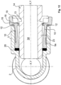
Weiterhin kann es erfindungsgemäß von Vorteil sein, wenn der den Muffenabschnitt gegenüberliegende Anschlussabschnitt des Gehäuses als Anschlusszapfen ausgebildet ist, wobei der Anschlusszapfen im Bereich seines freien Endes in einer Umfangsnut eine Umfangsdichtung aufweist und an dem dem freien Ende des Anschlusszapfens gegenüberliegenden Bereich mehrere sich in Richtung auf das freie Ende erstreckende, parallel zur Längsmittelachse des Anschlusszapfens verlaufende Raststege angeordnet sind, die am Umfang des Anschlusszapfens gleichmäßig beabstandet verteilt sind. Vorzugsweise sind hierbei erfindungsgemäß zwei diametral gegenüberliegende Raststege vorhanden. Die Raststege weisen an ihren freien Enden radial in Bezug auf die Längsmittelachse des Anschlusszapfens nach innen gerichtete Rastansätze auf. Erfindungsgemäß ist es weiterhin hierbei von Vorteil, dass zwischen den Raststegen und dem Anschlusszapfen ein Führungsspalt ausgebildet ist, in den eine Anschlusshülse eines Anschlussverbinders aufgeschoben werden kann, die eine innere Durchgangsbohrung aufweist, in der der Anschlusszapfen geführt ist, und wobei am freien Ende der Anschlusshülse an ihrem äußeren Umfang ein radial nach außen in Bezug auf die Längsmittelachse abstehender Ringansatz ausgebildet ist, der mit den Rastansätzen der Raststege korrespondierende Auflaufschrägen aufweist, so dass ein Aufschieben der Anschlusshülse möglich ist, wobei die Raststege radial nach außen gespreizt werden. Diese erfindungsgemäße Ausbildung von dem Anschlusszapfen und der Anschlusshülse ermöglicht eine axiale Relativverschiebung dieser Teile im Verbindungszustand zueinander. Durch diese Ausbildung wird die Crashsicherheit eines erfindungsgemäßen Steckverbinders wesentlich erhöht, denn diese erfindungsgemäße Ausbildung ermöglicht beispielsweise einen Längenausgleich von maximal 50 mm bis 60 mm, bevorzugt 20 mm Weg.Furthermore, it can be advantageous according to the invention if the connecting section of the housing opposite the socket section is designed as a connecting pin, the connecting pin having a peripheral seal in the area of its free end in a circumferential groove and in the area opposite the free end of the connecting pin there are several seals in the direction of the free end extending, parallel to the longitudinal center axis of the connecting pin extending latching webs are arranged, which are distributed on the circumference of the connecting pin spaced evenly. According to the invention, there are preferably two diametrically opposite latching webs. At their free ends, the locking webs have locking projections which are directed radially inwards in relation to the longitudinal center axis of the connecting pin. According to the invention, it is also advantageous here that a guide gap is formed between the latching webs and the connecting pin, into which a connecting sleeve of a connecting connector can be pushed, which has an inner through-bore in which the connecting pin is guided, and the free end of the connecting sleeve on its outer circumference there is a radially outwardly projecting ring extension in relation to the longitudinal central axis, which has ramps corresponding to the locking projections of the locking webs, so that it is possible to push on the connecting sleeve, with the locking webs being spread radially outwards. This inventive design of the connecting pin and the connecting sleeve allows an axial relative displacement of these parts to each other in the connected state. This design significantly increases the crash safety of a connector according to the invention, because this design according to the invention allows, for example, a length compensation of a maximum of 50 mm to 60 mm, preferably 20 mm.
Weiterhin bezieht sich die vorliegende Erfindung auf eine Steckkupplung bestehend aus einem Steckverbinder nach einer der vorgenannten Ausführungen sowie einem Gegensteckverbinder zum Einstecken in den erfindungsgemäßen Steckverbinder, wobei der Gegensteckverbinder einen Steckerschaft und eine in Einsteckrichtung hinter dem Steckerschaft ausgebildete Rastnut aufweist. Der Steckerschaft ist derart dimensioniert, dass im eingesteckten Zustand sein freies Ende aus der Adapterhülse herausragt und in dem Durchgangskanal des Gehäuses des Steckverbinders endet. Der Steckerschaft besitzt einen Außendurchmesser, der größer ist als ein radialer Abstand der Rastnocken der Federarme. Erfindungsgemäß kann es vorteilhaft sein, wenn die Rastnut eine derartige axiale Erstreckung in Richtung der Einsteckrichtung aufweist, dass ein axialer Verschiebeweg des Steckerschaftes im eingesteckten Zustand in der Adapterhülse um eine bestimmte Länge gegeben ist, und wobei die Länge des Steckerschaftes zwischen der Rastnut und seinem freien Ende derart bemessen ist, dass der Steckerschaft um die Länge des axialen Verschiebeweges verlängert ist, so dass er in jeder Lage mit seinem freien Ende aus der Adapterhülse herausragt und in dem Durchgangskanal des Gehäuses endet. Diese vorteilhafte Ausbildung ermöglicht einen Längenausgleich beispielsweise um einen Weg von 5 mm.Furthermore, the present invention relates to a plug-in coupling consisting of a plug connector according to one of the aforementioned embodiments and a mating connector for plugging into the plug connector according to the invention, the mating connector having a plug shank and a plug in the direction of insertion having locking groove formed behind the plug shank. The plug shank is dimensioned in such a way that when it is plugged in, its free end protrudes from the adapter sleeve and ends in the passage channel of the plug connector housing. The plug shank has an outer diameter that is larger than a radial distance between the locking cams of the spring arms. According to the invention, it can be advantageous if the locking groove has such an axial extension in the direction of insertion that there is an axial displacement path of the plug shank in the inserted state in the adapter sleeve by a certain length, and the length of the plug shank between the locking groove and its free End is dimensioned such that the plug shank is extended by the length of the axial displacement path, so that it protrudes in any position with its free end from the adapter sleeve and ends in the through channel of the housing. This advantageous design enables a length compensation, for example, by a distance of 5 mm.
Der erfindungsgemäße Steckverbinder bzw. die erfindungsgemäße Steckkupplung findet insbesondere Anwendung in Leitungssystemen für Batteriekühlsysteme, Kraftstoffleitungen, Kühlwasserleitungen und bei der Tankentlüftungsleitung für beispielsweise Adblue-Tanks. Es liegt eine Eignung insbesondere bis zu einem Druckbereich bis maximal 5 bar, vorzugsweise 2 bar vor. Darüber hinaus zeichnet sich der erfindungsgemäße Steckverbinder durch eine sehr kompakte Bauweise aus, und der Gegensteckverbinder besitzt eine sehr einfache konstruktive Ausgestaltung.The plug connector according to the invention or the plug-in coupling according to the invention is used in particular in line systems for battery cooling systems, fuel lines, cooling water lines and in the tank ventilation line for AdBlue tanks, for example. It is suitable in particular up to a pressure range of up to a maximum of 5 bar, preferably 2 bar. In addition, the connector according to the invention is characterized a very compact design, and the mating connector has a very simple structural design.
Vorteilhafte Ausgestaltungen der Erfindung sind in den Unteransprüchen enthalten. Anhand der in den beiliegenden Zeichnungen dargestellten Ausführungsbeispiele wird die Erfindung näher erläutert. Es zeigen:
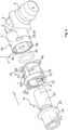
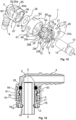
- Fig. 1
- eine perspektivische Explosionsdarstellung einer ersten Ausführungsform eines Steckverbinders und Gegensteckverbinders,
- Fig. 2
- eine Frontansicht auf eine erfindungsgemäße Adapterhülse gemäß
Fig. 1 , - Fig. 3
- einen Schnitt entlang der Schnittlinie III-III in
Fig. 2 , - Fig. 4
- einen Längsschnitt durch einen Steckverbinder gemäß
Fig. 1 im eingesteckten Zustand des Gegensteckverbinders, - Fig. 5
- eine perspektivische Explosionsdarstellung einer weiteren Ausführungsform eines Steckverbinders mit Gegensteckverbinder,
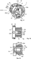
- Fig. 6
- eine Frontansicht einer Adapterhülse gemäß
Fig. 5 , - Fig. 7
- einen Schnitt entlang der Schnittlinie VII-VII in
Fig. 6 , - Fig. 8
- einen Längsschnitt durch eine Ausgestaltung gemäß
Fig. 5 im gesteckten Zustand des Gegensteckverbinders, - Fig. 9
- einen Schnitt gemäß
Fig. 8 bei einer weiteren Ausführungsform eines Steckverbinders und Gegensteckverbinders, - Fig. 10
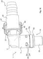
- eine perspektivische Seitenansicht einer weiteren Ausführungsform eines Steckverbinders und eines zugehörigen Anschlussverbinders,
- Fig. 11
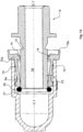
- einen Längsschnitt durch die Ausführungsform gemäß
Fig. 10 , - Fig. 12 und Fig. 13
- Längsschnitte durch einen Steckverbinder und einen nicht vollständig eingesteckten Gegensteckverbinder entsprechend den Ausführungen gemäß
Fig. 1 undFig. 5 , - Fig. 14
- einen Schnitt gemäß
Fig. 8 durch eine weitere Ausführungsform eines Steckverbinders, - Fig. 14a
- eine Vergrößerung als Detailansicht eines Ausschnitts B in
Fig. 14 , - Fig. 15
- eine Explosionsdarstellung einer Ausführungsform eines erfindungsgemäßen Steckverbinders,
- Fig. 16
- einen Schnitt durch einen Steckverbinder gemäß
Fig. 15 im eingesteckten Zustand des Gegensteckverbinders, - Fig. 17
- eine perspektivische Darstellung einer Adapterhülse gemäß
Fig. 15 , - Fig. 18
- eine Ansicht auf die Adapterhülse gemäß
Fig. 17 in Richtung des Pfeils XVIII und - Fig. 19
- eine Ansicht auf die Adapterhülse gemäß
Fig. 17 entsprechend dem Pfeil XIX inFig. 17 .
- 1
- a perspective exploded view of a first embodiment of a connector and mating connector,
- 2
- according to a front view of an adapter sleeve according to the
invention 1 , - 3
- a section along section line III-III in
2 , - 4
- according to a longitudinal section through a
connector 1 when the mating connector is plugged in, - figure 5
- a perspective exploded view of a further embodiment of a connector with a mating connector,
- 6
- according to a front view of an adapter sleeve
figure 5 , - 7
- a section along line VII-VII in
6 , - 8
- a longitudinal section through an embodiment according to
figure 5 when the mating connector is plugged in, - 9
- a cut according to
8 in a further embodiment of a connector and mating connector, - 10
- a perspective side view of a further embodiment of a plug connector and an associated terminal connector,
- 11
- according to a longitudinal section through the
embodiment 10 , - 12 and 13
- Longitudinal sections through a connector and an incompletely inserted mating connector according to the explanations in
1 andfigure 5 , - 14
- a cut according to
8 by another embodiment of a connector, - 14a
- an enlargement as a detailed view of a section B in
14 , - 15
- an exploded view of an embodiment of a connector according to the invention,
- 16
- according to a section through a
connector 15 when the mating connector is plugged in, - 17
- a perspective view of an adapter sleeve according to
15 , - 18
- a view of the adapter sleeve according to FIG
17 in the direction of arrow XVIII and - 19
- a view of the adapter sleeve according to FIG
17 according to the arrow XIX in17 .
In den verschiedenen Figuren der Zeichnung sind gleiche Teile stets mit denselben Bezugszeichen versehen.In the various figures of the drawing, the same parts are always provided with the same reference numbers.
Wie in
Das Gehäuse 2 weist einen Durchgangskanal 5 auf. Der Durchgangskanal 5 besitzt im Bereich des Muffenabschnitts 3 einen im Durchmesser vergrößerten Kanalabschnitt 6.The
In den Muffenabschnitt 3 mit dem im Durchmesser vergrößerten Kanalabschnitt 6 des Gehäuses 2 wird eine Adapterhülse 7 eingesetzt. Diese Adapterhülse 7 weist eine Durchgangsöffnung 8 auf. Weiterhin besitzt die Adapterhülse 7 eine die Durchgangsöffnung 8 umfassende Hülsenwandung 9. Insbesondere in zwei einander diametral gegenüberliegenden Abschnitten sind in der Hülsenwandung 9 Rastmittel ausgebildet. Diese Rastmittel bestehen vorzugsweise aus zwei in Bezug auf eine Längsmittelachse X-X der Adapterhülse 7 radial elastische Rastarme 10, die um 180° zueinander versetzt angeordnet sind. Diese Rastarme 10 verlaufen parallel der Längsmittelachse X-X und sind durch schlitzförmige Freischnitte 11 an ihren Längsseiten von der Hülsenwandung 9 getrennt. An ihrem in Einsteckrichtung Z vorderen Ende der Adapterhülse 7 sind die Rastarme 10 an die Hülsenwandung 9 angebunden. Hierbei besitzen die Rastarme 10 vorzugsweise eine geringere Dicke als die Wandstärke der Hülsenwandung 9, so dass zwischen dem Außenumfang der Hülsenwandung 9 und den Rastarmen 10 eine in Richtung auf die Längsmittelachse X-X verlaufende Stufenfläche 9a ausgebildet ist.An
Wie in
Die Rastarme 10 weisen zum Beispiel an ihren freien Enden radial, in Richtung auf die Längsmittelachse X-X ausgerichtete Rastnocken 12 auf. Diese Rastnocken 12 rasten im in die Durchgangsöffnung 8 eingesteckten Zustand der Adapterhülse 7 in eine Rastnut 13 eines Gegensteckverbinders 14 ein. Diese Rastnocken 12 liegen außerhalb des Muffenabschnitts 3 im eingesteckten Zustand der Adapterhülse 7The latching
Weiterhin kann es zweckmäßig sein, wenn die Adapterhülse 7 am Umfang ihrer Durchgangsöffnung 8, d. h. im in Einsteckrichtung Z gesehen hinten liegenden Öffnungsbereich, einen Ringkragen 15 auf. Dieser Ringkragen 15 erstreckt sich radial gegenüber der Hülsenwandung 9 nach außen, so dass sein Außendurchmesser größer ist als der Außendurchmesser der Hülsenwandung 9 und zweckmäßigerweise gleich groß wie der Außendurchmesser des Muffenabschnitts 3. Der Ringkragen 15 bildet eine Art Einsteckbegrenzung für die Adapterhülse 7, wobei der Ringkragen 15 sich im eingesteckten Zustand der Adapterhülse 7 außerhalb des Muffenabschnittes 3 befindet.Furthermore, it can be useful if the
An den Rastarmen 10 sind insbesondere an deren freien Enden in Bezug auf die Längsmittelachse X-X radial nach außen abstehende, stegartige Betätigungsfortsätze 16 ausgebildet. Diese Betätigungsfortsätze 16 verlaufen durch radial verlaufende Ausschnitte 17, und zwar in Bezug auf die Längsmittelachse X-X, so dass der Ringkragen 15 durch diese Ausschnitte 17 unterbrochen ist. An ihren freien Enden besitzen die Betätigungsfortsätze 16 entgegen der Einsteckrichtung Z abgewinkelte Fortsätze 18, die parallel zur Längsmittelachse X-X verlaufen. Diese Fortsätze 18 verlaufen zweckmäßigerweise bündig zum Außenumfang des Ringkragens 15, so dass der radiale Abstand der abgewinkelten Fortsätze 18 an ihrer Außenfläche gleich dem Außendurchmesser des Ringkragens 15 ist. Im Bereich der Fortsätze 18 sind in dem Ringkragen 15 tangential zur Durchgangsöffnung 8 der Adapterhülse 7 in radialer Richtung nach außen randoffene, im Querschnitt U-förmige Führungsnuten 19 ausgebildet. Die Fortsätze 18 und die Führungsnuten 19 bilden eine Durchstecköffnung für ein Lösewerkzeug 20. Dieses Lösewerkzeug 20 besitzt z. B. einen gabelförmigen Endabschnitt 21 mit zwei diametral gegenüberliegenden Gabelzinken 22. Der Abstand der Gabelzinken 22 entspricht dem radialen Abstand der Führungsnuten 19 im Bereich ihrer Bodenabschnitte. Die Breite der Gabelzinken 22 ist kleiner/gleich der Breite der Führungsnuten 19. Die Gabelzinken 22 besitzen an ihren freien Enden eine Höhe, die kleiner ist als der radiale Abstand der abgewinkelten Fortsätze 18 zum Bodenabschnitt der Führungsnuten 19. Von ihrem freien Ende aus nimmt die Höhe der Gabelzinken 22 stetig zu auf ein Höhenendmaß. Dieses Höhenendmaß ist derart, dass durch Einführen der Gabelzinken 22 senkrecht zur Längsmittelachse X-X in die von den Fortsätzen 18 und den Führungsnuten 19 gebildeten Durchstecköffnungen die Rastarme 10 radial nach außen elastisch gebogen werden, und zwar derart, dass der radiale Abstand ihrer Rastnocken 12 größer ist als der Außendurchmesser eines Steckerschaftes 23 des Gegensteckverbinders 14. Befindet sich der Steckerschaft 23 im eingesteckten Zustand des Gegensteckverbinders 14 innerhalb der Adapterhülse 7, wobei die Rastnocken 12 in die Rastnut 13 des Gegensteckverbinders 14 eingerastet sind, kann durch Einstecken des Lösewerkzeuges 20 in die Führungsnuten 19 die Einraststellung der Rastnocken 12 aufgehoben und der Steckerschaft 23 aus der Adapterhülse 7 herausgezogen werden.Web-
Der Gegensteckverbinder 14 besitzt den Steckerschaft 23, der einen kreisförmigen Querschnitt senkrecht zu seiner Mittelachse Y-Y aufweist. Der Außendurchmesser des Steckerschafts 23 ist größer als ein radialer Abstand der Rastnocken 12, so dass die Rastarme 10 beim Einstecken des Steckerschaftes 23 radial nach außen verbogen werden. An seinem in Einsteckrichtung Z vorderen Ende weist der Steckerschaft 23 die umfänglich verlaufende Rastnut 13 auf. Die Rastnut 13 weist eine in Einsteckrichtung Z vordere, senkrecht zur Mittelachse Y-Y verlaufende Anlagefläche auf, die mit einer ebenfalls senkrecht zur Längsmittelachse X-X verlaufenden Anlagefläche des Rastnockens 12 derart zusammenwirkt, dass ein Formschluss in im eingerasteten Zustand axialer Richtung gegeben ist, so dass ein selbstständiges Lösen des Steckerzapfens bzw. des Steckerschaftes 23 unter Zugbeanspruchung nicht erfolgen kann. An dem dem Steckerschaft 23 gegenüberliegenden Ende des Gegensteckverbinders 14 ist ein Anschlussabschnitt 24 zum Anschluss einer Fluidleitung oder eines Aggregates vorgesehen. Zwischen dem Anschlussabschnitt 24 und der Rastnut 13 des Gegensteckverbinders 14 ist zweckmäßigerweise ein Ringbund 25 angeformt, der als Anschlag dienen kann.The
Die Länge des Steckerschaftes 23 ist derart bemessen, dass dieser im eingesteckten Zustand in die Adapterhülse 7 mit seinem freien Ende aus der Adapterhülse 7 herausragt und bis in den Durchgangskanal 5 des Gehäuses 2 sich erstreckt.The length of the
Weiterhin ist vorteilhaft vorgesehen, dass innerhalb des Muffenabschnittes 3 eine Umfangsdichtung 26 in Einsteckrichtung Z vor der Adapterhülse 7 angeordnet ist. Diese Umfangsdichtung 26 dichtet den Umfangsspalt zwischen dem Steckerschaft 23 in dessen eingesteckten Zustand und der Innenwandung des Muffenabschnitts 3 ab. Die Umfangsdichtung 26 ist vorzugsweise als O-Dichtring ausgebildet und wird innerhalb des Muffenabschnitts 3 zwischen einer inneren Ringschulter 27 des Muffenabschnitts 3 am Übergang des Muffenabschnitts 3 und einer Stirnendfläche der Adapterhülse 7 eingekammert. Aufgrund dieser erfindungsgemäßen Ausgestaltung entfällt die Ausbildung einer Aufnahmenut für die Umfangsdichtung 26, so dass fertigungsmäßig die Ausbildung von Hinterschnitten nicht erforderlich ist. Darüber hinaus ist die Umfangsdichtung 26 im montierten Zustand der Adapterhülse 7 im Innern des Muffenabschnitts 3 geschützt angeordnet. Der Innendurchmesser des Durchgangskanals 5 des Gehäuses 2 und der Innendurchmesser der Durchgangsöffnung 8 der Adapterhülse 7 sind an den Außendurchmesser des Steckerschaftes 23 des Gegensteckverbinders 14 angepasst. Zweckmäßigerweise sind der Innendurchmesser des Durchgangskanals 5 und der Durchgangsöffnung 8 gleich groß. Durch eine elastische Verformung des Dichtrings 26, die durch das Einstecken des Steckerschaftes 23 verursacht wird, erfolgt einerseits eine Abdichtung nach außen und andererseits eine Fixierung des Steckerschaftes 23 in der Adapterhülse 7 bzw. im Muffenabschnitt 3 durch die innerhalb der O-Dichtung erzeugten Verformungsspannung.Furthermore, it is advantageously provided that a
Die Ringstufe 9b der Adapterhülse 7 besitzt eine radial zur Längsmittelachse X-X verlaufende, umlaufende Anlagefläche 27a. Wie in
Durch die vorstehende Ausbildung erfolgt ein geometrischer Abschluss der Aufnahme für die Umfangsdichtung 26, eine Begrenzung des Übersteckwegs bei der Montage der Adapterhülse 7, eine Aufnahme bzw. Weiterleitung der Aufdornkraft, sowie eine Aufrechterhaltung eines Spaltmaßes zwischen dem Muffenabschnitt 3 des Gehäuses 2 und der Adapterhülse 7.The above design results in a geometric conclusion of the receptacle for the
Gemäß der Erfindung ist die Adapterhülse 7 innerhalb des Muffenabschnitts 3 mittels Formschlusselementen 28 in axialer und vorzugsweise auch umfangsgemäßer Richtung formschlüssig fixiert. Diese Formschlusselemente 28 bestehen vorzugsweise aus nach außen am Umfang der Adapterhülse 7 zwischen den Rastarmen 10 ausgebildeten, entgegen der Einsteckrichtung Z der Adapterhülse 7 gerichteten, radial elastisch verformbaren Rastzungen 29.According to the invention, the
Die Rastzungen 29 verlaufen zweckmäßig unter einem spitzen Winkel zur Längsmittelachse X-X schräg nach außen im Sinne einer DurchmesserVergrößerung. Die Rastzungen 29 korrespondieren mit Ausnehmungen 30 in der Umfangswand des Muffenabschnitts 3. Im eingesteckten Zustand der Adapterhülse 7 in den Muffenabschnitt 3 rasten die Rastzungen 29 in die Ausnehmungen 30 formschlüssig ein. Die Ausnehmungen 30 sind vorteilhafterweise als Durchbrüche der Wandung des Muffenabschnitts 3 ausgebildet. Die Rastzungen 29 sind insbesondere derart dimensioniert, dass ihre freien Enden im eingerasteten Zustand nicht aus den Durchbrüchen herausragen. Die Rastzungen 29 weisen an ihren freien Enden senkrecht zur Längsmittelachse X-X der Adapterhülse 7 verlaufende Endflächen auf, und die Ausnehmungen 30 weisen den Endflächen der Rastzungen 29 gegenüberliegende Anlageflächen auf, die ebenfalls senkrecht zur Längsmittelachse X-X verlaufen. Diese Ausbildung der gegenüberliegenden Flächen bedingt im eingerasteten Zustand einen Formschluss in axialer Richtung. Zweckmäßigerweise sind die Rastzungen 29 und die Ausnehmungen 30 derart aneinander angepasst, dass im eingerasteten Zustand eine Verdrehung der Adapterhülse 7 nicht möglich ist.The latching
In den
Die Montage der Adapterhülse 7 bei den dargestellten Ausführungsformen erfolgt erfindungsgemäß derart, dass zunächst die Umfangsdichtung 26 in den Muffenabschnitt 3 eingebracht wird. Danach wird die Adapterhülse 7 in den Muffenabschnitt 3 eingesteckt, bis ihre Formschlusselemente 28, d. h. die Rastzungen 29, in die Ausnehmungen 30 eingerastet sind. In den derart fertig montierten erfindungsgemäßen Steckverbinder 1 wird der Gegensteckverbinder 14 eingesteckt, wobei im eingesteckten Zustand die Rastnocken 12 der Rastarme 10 in die Rastnut 13 des Gegensteckverbinders 14 einrasten.According to the invention, the assembly of the
Der Anschlussabschnitt 24 des Gegensteckverbinders 14 kann als Anschlusshülse zum Einstecken oder Einschrauben eines Fluidanschlusses oder eines weiteren Verbinderteils ausgebildet sein, siehe
Durch den Gegensteckverbinder 14 verläuft ein Fluidkanal 34, der zweckmäßigerweise einen Kanal-Innendurchmesser aufweist, der dem Innendurchmesser des Durchgangskanals 5 des Gehäuses 2 entspricht.A
Wie in
In
In
In den
Im Übrigen sind gleiche Teile wie in den
Gemäß der Erfindung kann der dem Muffenabschnitt 3 gegenüberliegende Steckabschnitt 4 des Steckverbinders 1 als Hülse zum Einstecken oder Einschrauben eines Leitungsanschlusses oder beispielsweise als Steckerzapfen, siehe
Zudem bezieht sich die vorliegende Erfindung auch auf einen Steckverbinder 1, bei dem der dem Muffenabschnitt 3 gegenüberliegende Steckabschnitt 4 als Anschlusszapfen 37 ausgebildet ist, siehe
Am freien Ende weist die Anschlusshülse 42 an ihrem äußeren Umfang einen radial nach außen in Bezug auf die Längsmittelachse Y1-Y1 abstehenden Ringansatz 44 auf. Dieser Ringansatz 44 und die Rastansätze 41 weisen korrespondierende Auflaufschrägflächen 50a, 50b auf, so dass bei einem Aufschieben der Anschlusshülse 42 die Raststege 40 radial nach außen gespreizt werden. Die Rastansätze 41 und der Ringansatz 44 sind derart zueinander dimensioniert, dass die Rastansätze 41 einen axialen Anschlag für den Ringansatz 44 darstellen. Hierzu weisen beide Teile senkrecht zur Längsmittelachse Y1-Y1 verlaufende, einander zugekehrte Anschlagflächen 50a, 50b auf. Diese erfindungsgemäße Ausbildung von dem Anschlusszapfen 37 und der Anschlusshülse 42 ermöglicht eine axiale Relativverschiebung dieser Teile im Verbindungszustand zueinander. Hierbei wird der axiale Verschiebeweg durch die Länge der Raststege 40 bis zu den Rastansätzen 41 bestimmt. Hierbei kann beispielsweise ein Verschiebeweg von 20 mm und maximal von 50 bis 60 mm vorhanden sein, so dass ein entsprechender Längenausgleich vorhanden ist. Hierdurch wird die Crashsicherheit eines erfindungsgemäßen Steckverbinders 1 bzw. Anschlussverbinders 36 wesentlich erhöht. An dem der Anschlusshülse 42 gegenüberliegenden Ende des Anschlussverbinders 36 kann ein Anschlusszapfen oder eine Anschlusshülse für die Befestigung eines Fluidanschlusses ausgebildet sein. Innerhalb des Anschlussverbinders 36 kann ein ringförmiger Tiefenanschlag 45 für den Anschlusszapfen 37 ausgebildet sein.At the free end, the connecting
Des Weiteren bezieht sich die Erfindung auf eine Steckkupplung aus einem Steckverbinder mit dem Gegensteckverbinder gemäß den
In den
Hierbei sind funktionsgleiche Teile wie in den vorhergehenden Figuren mit denselben Bezugsziffern versehen.In this case, parts with the same function as in the previous figures are provided with the same reference numbers.
Die Adapterhülse 7 besitzt eine die Durchgangsöffnung 8 umfassende Hülsenwandung 9. In zwei einander diametral gegenüberliegenden Abschnitten sind in der Hülsenwandung 9 Rastmittel ausgebildet. Diese Rastmittel bestehen aus zwei in Bezug auf eine Längsmittelachse X-X der Adapterhülse 7 radialelastische Rastarme 10, die um 180 ° zueinander versetzt angeordnet sind. Diese Rastarme 10 verlaufen parallel zu der Längsmittelachse X-X und sind durch schlitzförmige Freischnitte 11 an ihren Längsseiten von der Hülsenwandung 9 getrennt. An ihrem in Einsteckrichtung Z vorderen Ende der Adapterhülse sind die Rastarme 10 an die Hülsenwandung 9 angebunden. Hierbei besitzen die Rastarme 10 eine geringere Dicke als die Wandstärke der Hülsenwandung 9, so dass zwischen dem Außenumfang der Hülsenwandung 9 und dem Rastarm 10 ein in Richtung auf die Längsmittelachse X-X verlaufende Stufenfläche 9a ausgebildet ist.The
Bei der Ausführungsform gemäß
Es ist zweckmäßig, wenn die Adapterhülse 7 am Umfang ihrer Durchgangsöffnung 8, d. h. im in Einsteckrichtung Z gesehen hinten liegenden Öffnungsbereich, einen Ringkragen 15 aufweist. Dieser Ringkragen 15 verläuft radial gegenüber der Hülsenwandung 9 nach außen versetzt, so dass sein Außendurchmesser und sein Innendurchmesser insbesondere größer sind als der Außendurchmesser der Hülsenwandung 9. Zweckmäßigerweise ist der Außendurchmesser des Ringkragens 15 gleich groß wie der des Muffenabschnitts 3, wie in
Im dargestellten Ausführungsbeispiel ist die Adapterhülse 7 innerhalb des Muffenabschnitts 3 mittel Formschlusselementen in axialer und vorzugsweise auch umfangsgemäßer Richtung formschlüssig fixiert. Diese Formschlusselemente bestehen aus am Umfang der Adapterhülse 7 zwischen den Rastarmen 9, 10 ausgebildeten, radialelastischen Rastmitteln. Diese Rastmittel werden insbesondere aus zwei axial parallel zur Längsmittelachse X-X verlaufenden, radialelastisch biegbaren Armen 29a gebildet. Diese Arme 29a sind jeweils um 90 ° zueinander versetzt zu den Rastarmen 10 angeordnet. Erfindungsgemäß sind die Arme 29a durch einen U-förmigen Schlitz 29b von der Wand der Adapterhülse 7 getrennt und mit ihrem entgegen der Einsteckrichtung Z weisenden Ende mit der Wand der Adapterhülse 7 einstückig verbunden, siehe
Die zweiten Rastnocken 29c korrespondieren mit Ausnehmungen 30 in der Umfangswand des Muffenabschnitts 3 derart, dass im eingesteckten Zustand der Adapterhülse 7 in den Muffenabschnitt 3 die zweiten Rastnocken 29c in die Ausnehmungen 30 formschlüssig einrasten. Die Ausnehmungen 30 sind vorteilhafterweise als Durchbrüche der Wandung des Muffenabschnitts 3 ausgebildet. Vorzugsweise sind vier jeweils um 90 ° zueinander versetzt angeordnete Ausnehmungen 30 in dem Muffenabschnitt 3 vorhanden. Die zweiten Rastnocken 29c sind insbesondere derart dimensioniert, dass ihre freien Enden im eingerasteten Zustand nicht aus den Durchbrüchen 30 herausragen. Indem vier um 90 ° zueinander versetzte Ausnehmungen 30 ausgebildet sind, kann die Adapterhülse 7 in um 90 ° zueinander verdrehte Positionen eingesteckt werden. Es liegt ebenfalls im Rahmen der Erfindung, wenn die Durchbrüche 30 als innere Vertiefungen ausgebildet sind, so dass die Umfangswandung des Muffenabschnitts 3 geschlossen ist.The
Die zweiten Rastnocken 29c rasten mit ihren senkrecht zur Längsmittelachse X-X verlaufenden Rastflächen 29e ein, und die Ausnehmungen 30 weisen den Rastflächen 29e gegenüberliegende Anlageflächen auf, die ebenfalls senkrecht zur Längsmittelachse X-X verlaufen. Diese Ausbildung der gegenüberliegenden Flächen bedingt im eingerasteten Zustand einen Formschluss in axialer Richtung. Zweckmäßigerweisen sind die zweiten Rastnocken 29c und die Ausnehmungen 30 derart aneinander angepasst, dass im eingerasteten Zustand eine Verdrehung der Adapterhülse 7 nicht möglich ist.The
An den Rastarmen 10 sind an deren freien Enden in Bezug auf die Längsmittelachse X-X radial nach außen abstehende, stegartige Betätigungsfortsätze 16 ausgebildet. Diese Betätigungsfortsätze 16 verlaufen durch radial verlaufende Ausschnitte 17, und zwar in Bezug auf die Längsmittelachse X-X, so dass der Ringkragen 15 durch diese Ausschnitte 17 unterbrochen ist. An ihren freien Enden besitzen die Betätigungsfortsätze 16 entgegen der Einsteckrichtung Z abgewinkelte Fortsätze 18, die parallel zur Längsmittelachse X-X verlaufen. Diese Fortsätze 18 verlaufen zweckmäßigerweise bündig zum Außenumfang des Ringkragens 15, so dass der radiale Abstand zur Längsmittelachse X-X der abgewinkelten Fortsätze 18 an ihrer Außenfläche, d. h. der Außendurchmesser der Fortsätze 18, gleich dem Außendurchmesser des Ringkragens 15 ist. Im Bereich der Fortsätze 18 sind in dem Ringkragen 15 tangential zur Durchgangsöffnung 8 der Adapterhülse 7 in radialer Richtung nach außen randoffene, im Querschnitt U-förmige Führungsnuten bzw. Ausschnitte 19 ausgebildet, so dass diese sekantenförmig verlaufen. Die Fortsätze 18 und die Führungsnuten bzw. Führungsausschnitte 19 bilden eine Durchstecköffnung für ein Lösewerkzeug 20. Dieses Lösewerkzeug 20 besitzt z. B. einen gabelförmigen Endabschnitt 21 mit zwei diametral gegenüberliegenden Gabelzinken 22. Der Abstand der Gabelzinken 22 entspricht dem radialen Abstand der Führungsnuten 19 im Bereich ihrer Bodenabschnitte. Die Breite der Gabelzinken 22 ist kleiner/gleich der Breite der Führungsnuten 19. Die Gabelzinken 22 besitzen an ihren freien Enden eine Höhe, die kleiner ist als der radiale Abstand der abgewinkelten Fortsätze 18 zum Bodenabschnitt der Führungsnuten 19. Von ihrem freien Ende aus nimmt die Höhe der Gabelzinken 22 stetig zu auf ein Höhenendmaß. Dies Höhenendmaß ist derart, dass durch Einführen der Gabelzinken 22 senkrecht zur Längsmittelachse X-X in die von den Fortsätzen 18 und den Führungsnuten 19 gebildeten Durchstecköffnungen die Rastarme 10 radial nach außen elastisch gebogen werden, und zwar derart, dass der radiale Abstand ihrer Rastnocken 12 größer ist als der Außendurchmesser eines Steckerschaftes 23 des Gegensteckverbinders 14. Befindet sich der Steckerschaft 23 im eingesteckten Zustand des Gegensteckverbinders 14 innerhalb der Adapterhülse 7, wobei die Rastnocken 12 in die Rastnut 13 des Gegensteckverbinders 14 eingerastet sind, kann durch Einstecken des Lösewerkzeuges 20 in die Führungsnuten 19 die Einraststellung der Rastnocken 12 aufgehoben und der Steckerschaft 23 aus der Adapterhülse 7 herausgezogen werden. Das Lösewerkzeug 20 besitzt vorteilhafterweise zwischen den Gabelzinken 22 einen parallel zu den Gabelzinken 22 verlaufenden Führungssteg 22a, der im eingeschobenen Zustand des Lösewerkzeugs 20 in einer Ausnehmung 22b in dem Ringkragen 15 geführt wird, so dass ein Verkanten des Lösewerkzeugs 20 verhindert wird. Vorzugsweise sind zwei einander gegenüberliegende Ausnehmungen 22b in dem Ringkragen vorgesehen.On the free ends of the locking
Wie in den
Vorteilhafterweise besteht gemäß dem dargestellten vorteilhaften Ausführungsbeispiel die Lösesicherung 60 aus einer den Muffenabschnitt 3 formschlüssig umfassenden Hülse 61. Diese Hülse 61 ist auf dem Muffenabschnitt 3 verschiebbar gelagert, und zwar zwischen den vorbeschriebenen beiden Stellungen. In der ersten Stellung befindet sich die Hülse 61 vollständig auf dem Muffenabschnitt 3, siehe
An dem Außenumfang des Muffenabschnitts 3 sind zweckmäßigerweise vier um 90 ° zueinander versetzt angeordnete Längsrippen 67 ausgeformt. Die Hülse 61 besitzt in Anpassung hieran in ihrer Hülsenwandung Führungsnuten 68 zur Aufnahme der Längsrippen 67. Hierdurch erfolgt ein lagerichtiges Aufstecken der Hülse 61 auf den Muffenabschnitt 3, wenn die Adapterhülse 7 noch nicht in den Muffenabschnitt 3 eingesteckt ist.Four
- 11
- Steckverbinderconnector
- 22
- GehäuseHousing
- 33
- Muffenabschnittsleeve section
- 44
- Steckabschnittmating section
- 55
- Durchgangskanalthrough channel
- 66
- Kanalabschnittcanal section
- 6a6a
- Abschnitt des Kanalabschnittssection of the canal section
- 77
- Adapterhülseadapter sleeve
- 88th
- Durchgangsöffnungpassage opening
- 99
- Hülsenwandungsleeve wall
- 9a9a
- Stufenflächestep surface
- 9b9b
- Ringstufering level
- 9c9c
- Führungsnutenguide grooves
- 9d9d
- Einführungsöffnunginsertion hole
- 9e9e
- Führungsrippenguide ribs
- 1010
- Rastarmelocking arms
- 1111
- Freischnitterelief cuts
- 1212
- Erste RastnockenFirst locking cam
- 1313
- Rastnutlocking groove
- 1414
- Gegensteckverbindermating connector
- 1515
- RingkragenGorget
- 15a15a
-
Ringkragen
Fig. 5-10 GorgetFigures 5-10 - 1616
- Betätigungsfortsätzeoperating extensions
- 1717
- Ausschnitteexcerpts
- 1818
- Fortsätze von 16extensions of 16
- 1919
- Führungsnutenguide grooves
- 2020
- Lösewerkzeugrelease tool
- 2121
- gabelförmiger Endabschnittforked end section
- 2222
- Gabelzinkenforks
- 22a22a
- Führungsstegguide bar
- 22b22b
- Ausnehmungrecess
- 2323
- Steckerschaftconnector shaft
- 2424
- Anschlussabschnittconnector section
- 2525
- Ringbundring collar
- 2626
- Umfangsdichtungperimeter seal
- 2727
- Ringschulterring shoulder
- 27a27a
- Anlageflächecontact surface
- 27b27b
- Anschlagflächestop surface
- 2828
- Formschlusselementeinterlocking elements
- 2929
- Rastzungenlocking tongues
- 29a29a
- Armepoor
- 29b29b
- Schlitzslot
- 29c29c
- Zweite RastnockenSecond locking cam
- 29d29d
- Schrägflächenbevels
- 29e29e
- Rastflächenrest areas
- 29f29f
- Versteifungsansatzstiffening approach
- 3030
- Ausnehmungenrecesses
- 3232
- Spaltgap
- 3333
- Verformungsabschnittedeformation sections
- 3434
- Fluidkanalfluid channel
- 3535
- Rastnut des Gegensteckverb.Locking groove of the mating connector.
- 3636
- Anschlussverbinderconnection connector
- 3737
- Anschlusszapfenconnection spigot
- 3838
- Innerer FluidkanalInternal Fluid Channel
- 3939
- Umfangsdichtung des AnschlusszapfensCircumferential seal of the connecting pin
- 4040
- Raststegelocking bars
- 4141
- Rastansätzelocking lugs
- 4242
- Anschlusshülseconnection sleeve
- 4343
- Anschlussverbinderport connector
- 4444
- Ringansatzring approach
- 4545
- Tiefenanschlagdepth stop
- 6060
- Lösesicherunganti-release device
- 6161
- Hülsesleeve
- 6262
- Umfang von 61scope of 61
- 6363
- Rastzungenlocking tongues
- 6464
- Rastansätzelocking lugs
- 6565
- Ausnehmungenrecesses
- 65a65a
- Ausnehmungenrecesses
- 6767
- Längsrippenlongitudinal ribs
- 6868
- Führungsnutenguide grooves
- ZZ
- Einsteckrichtunginsertion direction
- X-XX-X
- Längsmittelachselongitudinal central axis
- Y-YY Y
- Längsmittelachselongitudinal central axis
Claims (25)
- Connector (1) for connecting at least one fluid line with another fluid line or to a unit connection, the connector comprising a housing (2) with a through-channel (5), one end of the housing (2) being formed as a sleeve section (3) for receiving a mating connector (14) and having latching means (10, 12) for releasably attaching the mating connector (14), the latching means (10, 12) being a component of an adapter sleeve (7) which can be inserted into the sleeve section (3) which is held in the sleeve section (3) by means of positive-locking elements (28), and has a through-opening (8) for a plug shank (23) of the mating connector (14), in which the latching means are formed from at least two latching arms (10) which are radially elastic with respect to a longitudinal central axis (X-X) of the adapter sleeve (7), the latching arms (10) being integrally formed on the end of the adapter sleeve (7) which is located inside the sleeve section (3) in the inserted state, and the latching arms (10) having first latching cams (12) at their free end which run radially in the direction of the longitudinal central axis (X-X), wherein the positive-locking elements (28) are formed from radially elastically bendable arms (29a) each extending parallel to the longitudinal central axis (X-X), which arms are diametrically opposite and offset by 90° relative to the latching arms (10) and have second latching cams (29c) projecting radially outwardly at their free ends pointing in the insertion direction (Z),
characterized in that the latching arms (10) run parallel to the longitudinal central axis (X-X) and are formed on the circumference of the adapter sleeve (7) by slot-shaped cutouts (11) in the sleeve wall thereof, the arms (29a) being separated from the wall of the adapter sleeve (7) by a U-shaped slot (29b) and being integrally connected to the wall of the adapter sleeve (7) with its end pointing against the insertion direction (Z). - Connector (1) according to claim 1,
characterized in that the second latching cams (29c) of the arms (29a) each have an oblique surface (29d) pointing in the insertion direction (Z) and a latching surface (29e) facing against the insertion direction (Z) and extending vertically to the longitudinal central axis (X-X). - Connector (1) according to claim 1 or 2,
characterized in that the second latching cams (29c) of the arms (29a) lie with their free ends on a circumferential circle whose diameter is smaller than the outer diameter of the sleeve section (3) and larger than the inner diameter of the channel section (6) of the sleeve section (3). - Connector (1) according to any one of claims 1 to 3,
characterized in that the thickness of the latching arms (10) is less than the wall thickness of the adapter sleeve (7), so that a stepped surface (9a) extending radially in the direction of the longitudinal central axis (X-X) is formed between the outer circumference of the wall of the adapter sleeve (7) and the latching arms (10). - Connector (1) according to claim 4,
characterized in that the radial height of the stepped surface (9a) and the length of the latching arms (10) within the sleeve section (3) are dimensioned in such a way that a radially outwardly directed spring path of the first latching cams (12) is provided in such a way that the radial distance of the radially outwardly spread first latching cams (12) from the longitudinal central axis (X-X) is at least equal to the inner radius of the through-opening (8) of the adapter sleeve (7) and at least equal to the outer radius of the plug shank (14a) of the mating connector (14). - Connector (1) according to any one of claims 1 to 5,
characterized in that the positive-locking elements (28) are positively fixed in the circumferential direction of the adapter sleeve (7) in recesses (30) of the circumferential wall of the sleeve section (3), in particular four recesses (30) offset by 90° to one another being formed. - Connector (1) according to any one of claims 1 to 6,
characterized in that the adapter sleeve (7) has an annular collar (15) running around the circumference of its through-opening (8) at its rear opening edge as viewed in the insertion direction (Z), which annular collar (15) is arranged outside the sleeve section (3) when the adapter sleeve (7) is inserted, and the first latching cams (12) also run outside the sleeve section (3). - Connector (1) according to claim 7,
characterized in that the annular collar (15) is circularly circumferentially formed and its outer diameter is smaller than or equal to an outer diameter of a circular circumferential contour of the sleeve section (3) respectively an outer diameter of the sleeve section (3). - Connector (1) according to any one of claims 1 to 8,
characterized in that latching arms (10) offset by 180° with respect to one another are formed and actuating extensions (16) projecting radially outwardly with respect to the longitudinal central axis (X-X) are formed at the free ends of the latching arms (10). - Connector (1) according to claim 9,
characterized in that in the region of the actuating extensions (16) on the annular collar (15), open-edge guide grooves (19) respectively openings (19) are formed tangentially to the through-opening (8) of the adapter sleeve (7), in which the annular collar (15) being interrupted by the actuating extensions (16), and the actuating extensions (16) each having an extension (18) which runs parallel to the longitudinal central axis (X-X) outside the respective guide groove (19) and is angled counter to the insertion direction (Z), so that an insertion opening suitable for the introduction of a release tool (20) is formed between the extensions (18) and the guide grooves (19). - Connector (1) according to any one of claims 7 to 10,
characterized in that the annular collar (15a) is separated from the adapter sleeve (7) by circumferential gap sections between the latching arms (10) and surrounds the latching arms (10) in the region of the first latching cams (12) on the outer side thereof and is connected thereto in this region, and the annular collar (15a) has deformation sections (33) centrally between the latching arms (10) which are deformable under a force directed radially to the longitudinal central axis (X-X) in such a way that a radially outwardly directed spreading of the latching arms (10) is produced in such a way that the first latching cams (12) assume their release position. - Connector (1) according to claim 10,
characterized in that the radial distance of the angled extensions (18) of the actuating extensions (16) at their outer surfaces is equal to an outer diameter of the annular collar (15). - Connector (1) according to claim 12,
characterized in that an outer diameter of the annular collar (15a) in the region of the first latching cams (12) is equal to the outer diameter of the sleeve section (3). - Connector (1) according to any one of claims 1 to 13,
characterized in that a circumferential seal (26) is arranged in front of the adapter sleeve (7) in the through-opening (8) of the sleeve section (3) in the insertion direction (Z) for sealing a circumferential gap between an inner wall of the sleeve section (3) and the plug shank (23) of a mating connector (14). - Connector (1) according to any one of claims 1 to 14,
characterized in that on the outer circumference of the sleeve section (3) a release lock (60) is arranged slideably in the longitudinal direction (X-X) between two locking positions, wherein the release lock (60) in its second locking position slid on the annular collar (15) prevents spreading of the latching arms (10) and in its other locking position the latching arms (10) can be spread. - Connector (1) according to claim 15,
characterized in that the release lock (60) consists of a sleeve (61) which surrounds the sleeve section (3) and has, on its circumferential edge (62) pointing in the insertion direction (Z), latching tongues (63) which, in the respective latching position, latch into recesses (65) in the circumferential wall of the sleeve section (3). - Connector (1) according to claim 16,
characterized in that the sleeve (61) in its locking position blocking the spreading of the latching arms (10) surrounds the annular collar (15) as well as the extensions (18). - Connector (1) according to any one of claims 14 to 17,
characterized in that an annular shoulder (27) is formed in the sleeve section (3) at the transition of a channel section (6) of the sleeve section (3), which is enlarged in diameter, to the through-channel (5) for abutment of the circumferential seal (26) for sealing the circumferential gaps, and the circumferential seal (26) is chambered between the annular shoulder (27) and an front end surface of the adapter sleeve (7). - Connector (1) according to any one of claims 1 to 18,
characterized in that the housing (2) has, at its end opposite the sleeve section (3), a connecting pin (37) which has a circumferential seal (39) at its free end, and a plurality of latching webs (40) are arranged on the region of the connecting pin (37) opposite the free end, which latching webs extend in the direction of the free end, run parallel to the longitudinal central axis (Y-Y) and have, at their ends, latching projections (41) which are directed radially inwards with respect to the longitudinal central axis (Y-Y). - Connector (1) according to claim 19,
characterized in that a guide slot is formed between the latching web (40) and the connecting pin (37), into which guide slot a connecting sleeve (42) can be inserted which has a through-bore for receiving the connecting pin (37), and a ring insert projecting radially outwardly with respect to the longitudinal central axis (Y-Y), which ring insert, in the pushed-on state of the connecting sleeve (42), is displaceable within the guide slot between the latching projection (41) and the opposite end of the latching webs (40). - Connector (1) according to any one of claims 1 to 20,
characterized in that an annular step (9b) is formed in the insertion direction (Z) at the front end of the adapter sleeve (7) by a diameter reduction of the adapter sleeve (7), and guide grooves (9c) are formed starting from this annular step (9b) on the circumference of the adapter sleeve (7) and running parallel to the longitudinal central axis (X-X), the groove base of which lies on the same radius as the circumference of the annular step (9b), wherein in the inserted state of the adapter sleeve (7) the guide grooves (9c) serve to receive and guide guide ribs (9e) which are formed on the inside of the channel section (6) on its inner wall. - Connector (1) according to claim 21,
characterized in that the annular step (9b) of the adapter sleeve (7) has a circumferential contact surface (27a) extending radially with respect to the longitudinal central axis (X-X), and the section (6a) of the channel section (6) has an annular stop surface (27b) formed in the sense of an enlargement of the diameter, wherein in the inserted state of the adapter sleeve (7) the latter abuts with its contact surface (27a) against the stop surface (27b). - Plug-in coupling consisting of a connector (1) according to one of the claims 1 to 22 as well as a mating connector (14) for plugging into the connector (1) with a plug shank (23) and a latching groove (13) formed behind the plug shank (23) in the insertion direction (Z),
characterized in that the plug shank (23) is dimensioned in such a way that, in the plugged-in state, its free end projects out of the adapter sleeve (7) and ends in the through-channel (5) of the housing (2) of the connector (1), and its outer diameter is greater than the radial distance of the first latching cams (12) in the non-spread state. - Plug-in coupling according to claim 23,
characterized in that the latching groove (13) is arranged and formed in such a way that, when the plug shank (23) is inserted, the latching arms (10) engage with their first latching cams (12) in the latching groove (13) in a form-fitting manner. - Plug-in coupling according to claim 23 or 24,
characterized in that the latching groove (13) has such an axial extension in the direction of the insertion direction (Z) that an axial displacement of the plug shank (23) in the inserted state in the adapter sleeve (7) is given along a certain displacement path, and wherein the length of the plug shank (23) between the latching groove (13) and its free end is dimensioned such that the plug shank (23) is extended by the length of the axial displacement path.
Applications Claiming Priority (3)
| Application Number | Priority Date | Filing Date | Title |
|---|---|---|---|
| DE102014107655.9A DE102014107655A1 (en) | 2014-05-30 | 2014-05-30 | "Connector for fluid lines with internal adapter sleeve" |
| PCT/EP2015/057243 WO2015180875A1 (en) | 2014-05-30 | 2015-04-01 | Plug-in connector for fluid lines with inner adapter sleeve |
| PCT/EP2015/062178 WO2015181396A2 (en) | 2014-05-30 | 2015-06-01 | Plug connector for fluid lines, comprising an inner adapter sleeve |
Publications (2)
| Publication Number | Publication Date |
|---|---|
| EP3149383A2 EP3149383A2 (en) | 2017-04-05 |
| EP3149383B1 true EP3149383B1 (en) | 2023-08-02 |
Family
ID=53724284
Family Applications (2)
| Application Number | Title | Priority Date | Filing Date |
|---|---|---|---|
| EP15741903.7A Active EP3149384B1 (en) | 2014-05-30 | 2015-04-01 | Plug-in connector for fluid lines with inner adapter sleeve |
| EP15726599.2A Active EP3149383B1 (en) | 2014-05-30 | 2015-06-01 | Plug connector for fluid lines, comprising an inner adapter sleeve |
Family Applications Before (1)
| Application Number | Title | Priority Date | Filing Date |
|---|---|---|---|
| EP15741903.7A Active EP3149384B1 (en) | 2014-05-30 | 2015-04-01 | Plug-in connector for fluid lines with inner adapter sleeve |
Country Status (5)
| Country | Link |
|---|---|
| US (2) | US10465827B2 (en) |
| EP (2) | EP3149384B1 (en) |
| CN (3) | CN106461139B (en) |
| DE (1) | DE102014107655A1 (en) |
| WO (2) | WO2015180875A1 (en) |
Families Citing this family (32)
| Publication number | Priority date | Publication date | Assignee | Title |
|---|---|---|---|---|
| DE102014107655A1 (en) * | 2014-05-30 | 2015-12-03 | Voss Automotive Gmbh | "Connector for fluid lines with internal adapter sleeve" |
| DE102016110717B3 (en) * | 2016-06-10 | 2017-08-03 | HARTING Electronics GmbH | Connectors |
| US10006577B2 (en) | 2016-07-15 | 2018-06-26 | Miniature Precision Components, Inc. | Permanent quick connector and assembly therewith |
| CN109496254B (en) * | 2016-07-29 | 2021-07-16 | 福士汽车配套部件责任有限公司 | Holding element and connector having the same |
| DE102016009168A1 (en) | 2016-07-29 | 2018-02-01 | Voss Automotive Gmbh | terminal connector |
| CN106337985B (en) * | 2016-11-23 | 2017-12-05 | 黄松檀 | A kind of pipeline connector applied to pilotless automobile |
| CN106337984B (en) * | 2016-11-23 | 2017-11-10 | 黄松檀 | Assembling lock clasp in a kind of pipeline connector applied to pilotless automobile |
| KR102636742B1 (en) * | 2016-12-27 | 2024-02-15 | 현대자동차주식회사 | Hydraulic tube connector for vehicle |
| CN109717741B (en) * | 2017-03-10 | 2020-10-16 | 扬州市杭集创意设计园有限公司 | Water dispenser with liftable travelling wheels |
| DE102017004450A1 (en) * | 2017-05-09 | 2018-11-15 | Diehl Metering Gmbh | Arrangement for installation in a fluid line network |
| CN109404647A (en) * | 2017-08-17 | 2019-03-01 | A.雷蒙德公司 | Dismountable Quick Connect Kit |
| US10865922B2 (en) * | 2017-10-05 | 2020-12-15 | Novares Us Engine Components, Inc. | Anti-tamper permanent quick connect coupling device |
| CN108253857B (en) * | 2018-01-16 | 2024-01-19 | 西安物华巨能爆破器材有限责任公司 | Plug bush used between magneto-electric detonator and booster |
| JP2019148324A (en) * | 2018-02-28 | 2019-09-05 | トヨタ自動車株式会社 | Joint structure |
| DE102018212376A1 (en) | 2018-07-25 | 2020-01-30 | Contitech Mgw Gmbh | Fluid coupling with tolerance compensation for flexible connection of two media-carrying elements |
| CN109114321A (en) * | 2018-10-23 | 2019-01-01 | 黄子颢 | A kind of pipeline connecting assemble and pipeline |
| FR3072154B1 (en) * | 2018-11-12 | 2020-09-04 | Parker Hannifin Emea Sarl | FLUID TRANSPORT DUCTS CONNECTION KIT |
| DE102018219932A1 (en) | 2018-11-21 | 2020-05-28 | Fränkische Industrial Pipes GmbH & Co. KG | coupling |
| DE102018220521A1 (en) * | 2018-11-28 | 2020-05-28 | Fränkische Industrial Pipes GmbH & Co. KG | Fluid connection |
| CN110274112A (en) * | 2019-07-25 | 2019-09-24 | 浙江万全机械制造有限公司 | A kind of right angle plug connecting assembly for fluid conduit systems |
| DE102020203792A1 (en) | 2020-03-24 | 2021-09-30 | Hansgrohe Se | In-wall connection box unit |
| DE202020101638U1 (en) | 2020-03-24 | 2020-04-24 | Voss Automotive Gmbh | Connector with pre-assembly lock |
| DE102020108073A1 (en) | 2020-03-24 | 2021-09-30 | Voss Automotive Gmbh | Connector with pre-assembly lock |
| DE102020203800A1 (en) | 2020-03-24 | 2021-09-30 | Hansgrohe Se | Sanitary in-wall connection box unit with electrical cable feed-through |
| DE102020203797A1 (en) * | 2020-03-24 | 2021-09-30 | Hansgrohe Se | In-wall connection box unit with extension sleeve |
| DE102020110069A1 (en) | 2020-04-09 | 2021-10-14 | Sartorius Stedim Biotech Gmbh | Connection clamp for the mechanical connection of two bioprocess engineering system components |
| DE102021108451A1 (en) | 2021-04-01 | 2022-10-06 | Voss Automotive Gmbh | Connector for fluid lines with internal adapter sleeve |
| DE102021124681A1 (en) | 2021-09-23 | 2023-03-23 | Voss Automotive Gmbh | Connector with pre-assembly lock |
| CN113733161B (en) * | 2021-09-30 | 2023-01-17 | 北京空间飞行器总体设计部 | Quick interface device of end effector of mechanical arm |
| WO2023148189A1 (en) | 2022-02-01 | 2023-08-10 | Voss Automotive Gmbh | Plug connector with mounting protection |
| DE102022104970A1 (en) | 2022-02-01 | 2023-08-03 | Voss Automotive Gmbh | Connector with mounting lock |
| DE102022107490A1 (en) | 2022-03-30 | 2023-10-05 | Voss Automotive Gmbh | Modular connector |
Family Cites Families (30)
| Publication number | Priority date | Publication date | Assignee | Title |
|---|---|---|---|---|
| US2485763A (en) * | 1946-07-16 | 1949-10-25 | Signal Oil & Gas Co | Tool joint |
| US3782840A (en) * | 1971-10-05 | 1974-01-01 | Sealectro Corp | Mechanical coupling |
| US5275448A (en) * | 1991-09-10 | 1994-01-04 | Huron Products Industries, Inc. | Quick connect tubing connector and method of assembly |
| DE4214105A1 (en) | 1992-04-29 | 1993-11-04 | Voss Armaturen | CONNECTORS FOR HOSE OR PIPING, IN PARTICULAR FOR FUEL LINES OF COMBUSTION ENGINES |
| FR2717883B1 (en) * | 1994-03-04 | 1996-06-14 | Hutchinson | Quick and watertight connection device for tubular pipes. |
| US5915738A (en) * | 1995-07-28 | 1999-06-29 | Guest; John Derek | Tube couplings |
| GB9724521D0 (en) * | 1997-11-20 | 1998-01-21 | Munster Simms Engineering Limi | Pipe connections |
| DE19822574C1 (en) * | 1998-05-20 | 1999-10-14 | Raymond A & Cie | Fuel line quick coupling for motor vehicle |
| FR2780765B1 (en) * | 1998-07-01 | 2000-09-29 | Caillau Ets | QUICK CONNECTION PLUG HAVING A MONOBLOCK PIECE FORMING A LOCKING MEMBER AND A JOINT LOCKING RING |
| DE10115399C1 (en) * | 2001-03-29 | 2002-06-06 | Raymond A & Cie | Detachable push-fit coupling, for fluid pipes, has insert part and housing and with additional locking element displaced crosswise between opening and closing position |
| US6467816B1 (en) * | 2001-08-21 | 2002-10-22 | Huang-Fu Huang | Water pipe joint |
| EP1561990B1 (en) * | 2004-02-05 | 2008-08-20 | TI Group Automotive Systems LLC | Quick connector for high pressure applications |
| DE102004053538A1 (en) * | 2004-11-05 | 2006-05-11 | Veritas Ag | Coupling device for connecting lines and motor vehicle with such a coupling device |
| DE102005060135A1 (en) * | 2005-12-16 | 2007-07-05 | A. Raymond Et Cie | Coupling for connecting the ends of two pipes in a fluid pipe system has securing part with substantially closed annular sleeve with latching part(s) and locking piece(s) mounted on side of annular sleeve by radially sprung spring bridges |
| DE102006013899B3 (en) | 2006-03-25 | 2006-11-30 | Rasmussen Gmbh | Insertion coupling to connect two fluid lines has assembly indicator next to locking projection to project beyond locking projection sector of holding arm |
| DE102007009947B4 (en) * | 2007-03-01 | 2016-11-24 | Techpointe S.A. | male member |
| DE102007032324B4 (en) * | 2007-07-11 | 2012-10-31 | A. Raymond Et Cie | Fluid line coupling |
| DE102008013565A1 (en) * | 2008-03-11 | 2009-09-17 | A. Kayser Automotive Systems Gmbh | An insertion |
| JP5306868B2 (en) * | 2009-03-23 | 2013-10-02 | 株式会社ニフコ | Pipe connection connector |
| CN102782385B (en) * | 2010-03-05 | 2014-08-27 | 福士汽车配套部件责任有限公司 | Plug-type connector for media lines |
| DE102010010522B4 (en) * | 2010-03-05 | 2012-10-25 | Voss Automotive Gmbh | Connectors for media cables |
| NL2007552C2 (en) * | 2011-10-07 | 2013-04-09 | Andries Valk | Coupling device, line path and line end section. |
| DE102011084988B4 (en) | 2011-10-21 | 2022-07-28 | Fränkische Industrial Pipes GmbH & Co. KG | Connection unit and connection arrangement comprising such a connection unit |
| DE102011118099A1 (en) * | 2011-11-10 | 2013-05-16 | Illinois Tool Works Inc. | Device for connecting two line sections |
| DE202012000597U1 (en) * | 2012-01-13 | 2013-04-22 | Neoperl Gmbh | Detachable plug connection |
| DE102012106925A1 (en) * | 2012-07-30 | 2014-06-12 | Contitech Schlauch Gmbh | Quick connection arrangement for the detachable connection of a media line with a nozzle |
| DE102012107463A1 (en) * | 2012-08-15 | 2014-06-12 | Contitech Schlauch Gmbh | Quick connection arrangement for the detachable connection of a media line with a nozzle |
| EP2728236B1 (en) * | 2012-11-05 | 2017-04-19 | TI Automotive (Fuldabrück) GmbH | Quick connector coupling |
| EP3839317A1 (en) * | 2013-01-15 | 2021-06-23 | TI Automotive (Fuldabrück) GmbH | Quick coupling |
| DE102014107655A1 (en) * | 2014-05-30 | 2015-12-03 | Voss Automotive Gmbh | "Connector for fluid lines with internal adapter sleeve" |
-
2014
- 2014-05-30 DE DE102014107655.9A patent/DE102014107655A1/en active Pending
-
2015
- 2015-04-01 CN CN201580028898.6A patent/CN106461139B/en active Active
- 2015-04-01 EP EP15741903.7A patent/EP3149384B1/en active Active
- 2015-04-01 WO PCT/EP2015/057243 patent/WO2015180875A1/en active Application Filing
- 2015-04-01 US US15/315,303 patent/US10465827B2/en active Active
- 2015-05-29 CN CN201520364006.7U patent/CN205013931U/en active Active
- 2015-06-01 CN CN201580028897.1A patent/CN106461141B/en active Active
- 2015-06-01 WO PCT/EP2015/062178 patent/WO2015181396A2/en active Application Filing
- 2015-06-01 US US15/315,321 patent/US10670175B2/en active Active
- 2015-06-01 EP EP15726599.2A patent/EP3149383B1/en active Active
Also Published As
| Publication number | Publication date |
|---|---|
| CN205013931U (en) | 2016-02-03 |
| CN106461139B (en) | 2019-06-18 |
| US20170152980A1 (en) | 2017-06-01 |
| US10465827B2 (en) | 2019-11-05 |
| CN106461141B (en) | 2020-03-17 |
| CN106461141A (en) | 2017-02-22 |
| WO2015180875A1 (en) | 2015-12-03 |
| US20170152979A1 (en) | 2017-06-01 |
| EP3149383A2 (en) | 2017-04-05 |
| EP3149384A1 (en) | 2017-04-05 |
| DE102014107655A1 (en) | 2015-12-03 |
| EP3149384B1 (en) | 2022-10-05 |
| CN106461139A (en) | 2017-02-22 |
| WO2015181396A2 (en) | 2015-12-03 |
| WO2015181396A3 (en) | 2016-04-21 |
| US10670175B2 (en) | 2020-06-02 |
Similar Documents
| Publication | Publication Date | Title |
|---|---|---|
| EP3149383B1 (en) | Plug connector for fluid lines, comprising an inner adapter sleeve | |
| EP2076705B1 (en) | Coupling part for a fluid line coupling | |
| DE60113912T2 (en) | pipe coupling | |
| EP1969279B1 (en) | Coupling part for a plug connector arrangement | |
| EP2439439B1 (en) | Connecting element for a fluid connection | |
| EP1724510B1 (en) | Plug-in coupling | |
| EP2724065B1 (en) | Hose nipple and corresponding hose arrangement | |
| DE102010010522B4 (en) | Connectors for media cables | |
| DE202005015966U1 (en) | Connectors for media cables | |
| EP1969280B1 (en) | Plug-in part for a plug connector arrangement | |
| DE102008013565A1 (en) | An insertion | |
| EP4127543A1 (en) | Plug-type coupling with pre-assembly locking | |
| DE202020101638U1 (en) | Connector with pre-assembly lock | |
| EP1567800B9 (en) | Pluggable and lockable line connector | |
| EP0860643A2 (en) | Plug-in pressurized coupling | |
| EP1963728B1 (en) | Coupling | |
| DE19852395C2 (en) | plug-in coupling | |
| EP1838989B1 (en) | Connecting device for media pipes | |
| EP2281136B1 (en) | Plug connection for fluid conduits | |
| EP4071395B1 (en) | Connector for fluid conduits with internal adapter sleeve | |
| EP0691501B1 (en) | Plug-in connector for hoses and/or pipe conduits | |
| DE102013200620A1 (en) | Connector i.e. plug connector for connecting low-pressure line between reservoir and working cylinder in motor car, has socket part with mounting device that is displaced towards connector part, and detent device latched with connector part | |
| DE202009007099U1 (en) | Protective hose / pipe quick - fitting with front opener | |
| EP1746330A2 (en) | Female part of a fluid plug connection | |
| DE102022101100A1 (en) | fluid connection |
Legal Events
| Date | Code | Title | Description |
|---|---|---|---|
| STAA | Information on the status of an ep patent application or granted ep patent |
Free format text: STATUS: THE INTERNATIONAL PUBLICATION HAS BEEN MADE |
|
| PUAI | Public reference made under article 153(3) epc to a published international application that has entered the european phase |
Free format text: ORIGINAL CODE: 0009012 |
|
| STAA | Information on the status of an ep patent application or granted ep patent |
Free format text: STATUS: REQUEST FOR EXAMINATION WAS MADE |
|
| 17P | Request for examination filed |
Effective date: 20161228 |
|
| AK | Designated contracting states |
Kind code of ref document: A2 Designated state(s): AL AT BE BG CH CY CZ DE DK EE ES FI FR GB GR HR HU IE IS IT LI LT LU LV MC MK MT NL NO PL PT RO RS SE SI SK SM TR |
|
| AX | Request for extension of the european patent |
Extension state: BA ME |
|
| RIN1 | Information on inventor provided before grant (corrected) |
Inventor name: KLEIN, ROLAND Inventor name: HEINRICHS, EUGEN |
|
| DAV | Request for validation of the european patent (deleted) | ||
| DAX | Request for extension of the european patent (deleted) | ||
| STAA | Information on the status of an ep patent application or granted ep patent |
Free format text: STATUS: EXAMINATION IS IN PROGRESS |
|
| 17Q | First examination report despatched |
Effective date: 20190521 |
|
| STAA | Information on the status of an ep patent application or granted ep patent |
Free format text: STATUS: EXAMINATION IS IN PROGRESS |
|
| STAA | Information on the status of an ep patent application or granted ep patent |
Free format text: STATUS: EXAMINATION IS IN PROGRESS |
|
| GRAP | Despatch of communication of intention to grant a patent |
Free format text: ORIGINAL CODE: EPIDOSNIGR1 |
|
| STAA | Information on the status of an ep patent application or granted ep patent |
Free format text: STATUS: GRANT OF PATENT IS INTENDED |
|
| INTG | Intention to grant announced |
Effective date: 20220520 |
|
| GRAJ | Information related to disapproval of communication of intention to grant by the applicant or resumption of examination proceedings by the epo deleted |
Free format text: ORIGINAL CODE: EPIDOSDIGR1 |
|
| STAA | Information on the status of an ep patent application or granted ep patent |
Free format text: STATUS: EXAMINATION IS IN PROGRESS |
|
| INTC | Intention to grant announced (deleted) | ||
| GRAP | Despatch of communication of intention to grant a patent |
Free format text: ORIGINAL CODE: EPIDOSNIGR1 |
|
| STAA | Information on the status of an ep patent application or granted ep patent |
Free format text: STATUS: GRANT OF PATENT IS INTENDED |
|
| INTG | Intention to grant announced |
Effective date: 20221220 |
|
| GRAS | Grant fee paid |
Free format text: ORIGINAL CODE: EPIDOSNIGR3 |
|
| GRAA | (expected) grant |
Free format text: ORIGINAL CODE: 0009210 |
|
| STAA | Information on the status of an ep patent application or granted ep patent |
Free format text: STATUS: THE PATENT HAS BEEN GRANTED |
|
| AK | Designated contracting states |
Kind code of ref document: B1 Designated state(s): AL AT BE BG CH CY CZ DE DK EE ES FI FR GB GR HR HU IE IS IT LI LT LU LV MC MK MT NL NO PL PT RO RS SE SI SK SM TR |
|
| REG | Reference to a national code |
Ref country code: GB Ref legal event code: FG4D Free format text: NOT ENGLISH |
|
| REG | Reference to a national code |
Ref country code: CH Ref legal event code: EP |
|
| REG | Reference to a national code |
Ref country code: DE Ref legal event code: R096 Ref document number: 502015016519 Country of ref document: DE |
|
| P01 | Opt-out of the competence of the unified patent court (upc) registered |
Effective date: 20230714 |
|
| REG | Reference to a national code |
Ref country code: IE Ref legal event code: FG4D Free format text: LANGUAGE OF EP DOCUMENT: GERMAN |
|
| REG | Reference to a national code |
Ref country code: LT Ref legal event code: MG9D |
|
| REG | Reference to a national code |
Ref country code: NL Ref legal event code: MP Effective date: 20230802 |
|
| PG25 | Lapsed in a contracting state [announced via postgrant information from national office to epo] |
Ref country code: GR Free format text: LAPSE BECAUSE OF FAILURE TO SUBMIT A TRANSLATION OF THE DESCRIPTION OR TO PAY THE FEE WITHIN THE PRESCRIBED TIME-LIMIT Effective date: 20231103 |
|
| PG25 | Lapsed in a contracting state [announced via postgrant information from national office to epo] |
Ref country code: IS Free format text: LAPSE BECAUSE OF FAILURE TO SUBMIT A TRANSLATION OF THE DESCRIPTION OR TO PAY THE FEE WITHIN THE PRESCRIBED TIME-LIMIT Effective date: 20231202 |
|
| PG25 | Lapsed in a contracting state [announced via postgrant information from national office to epo] |
Ref country code: SE Free format text: LAPSE BECAUSE OF FAILURE TO SUBMIT A TRANSLATION OF THE DESCRIPTION OR TO PAY THE FEE WITHIN THE PRESCRIBED TIME-LIMIT Effective date: 20230802 Ref country code: RS Free format text: LAPSE BECAUSE OF FAILURE TO SUBMIT A TRANSLATION OF THE DESCRIPTION OR TO PAY THE FEE WITHIN THE PRESCRIBED TIME-LIMIT Effective date: 20230802 Ref country code: PT Free format text: LAPSE BECAUSE OF FAILURE TO SUBMIT A TRANSLATION OF THE DESCRIPTION OR TO PAY THE FEE WITHIN THE PRESCRIBED TIME-LIMIT Effective date: 20231204 Ref country code: NO Free format text: LAPSE BECAUSE OF FAILURE TO SUBMIT A TRANSLATION OF THE DESCRIPTION OR TO PAY THE FEE WITHIN THE PRESCRIBED TIME-LIMIT Effective date: 20231102 Ref country code: NL Free format text: LAPSE BECAUSE OF FAILURE TO SUBMIT A TRANSLATION OF THE DESCRIPTION OR TO PAY THE FEE WITHIN THE PRESCRIBED TIME-LIMIT Effective date: 20230802 Ref country code: LV Free format text: LAPSE BECAUSE OF FAILURE TO SUBMIT A TRANSLATION OF THE DESCRIPTION OR TO PAY THE FEE WITHIN THE PRESCRIBED TIME-LIMIT Effective date: 20230802 Ref country code: LT Free format text: LAPSE BECAUSE OF FAILURE TO SUBMIT A TRANSLATION OF THE DESCRIPTION OR TO PAY THE FEE WITHIN THE PRESCRIBED TIME-LIMIT Effective date: 20230802 Ref country code: IS Free format text: LAPSE BECAUSE OF FAILURE TO SUBMIT A TRANSLATION OF THE DESCRIPTION OR TO PAY THE FEE WITHIN THE PRESCRIBED TIME-LIMIT Effective date: 20231202 Ref country code: HR Free format text: LAPSE BECAUSE OF FAILURE TO SUBMIT A TRANSLATION OF THE DESCRIPTION OR TO PAY THE FEE WITHIN THE PRESCRIBED TIME-LIMIT Effective date: 20230802 Ref country code: GR Free format text: LAPSE BECAUSE OF FAILURE TO SUBMIT A TRANSLATION OF THE DESCRIPTION OR TO PAY THE FEE WITHIN THE PRESCRIBED TIME-LIMIT Effective date: 20231103 Ref country code: FI Free format text: LAPSE BECAUSE OF FAILURE TO SUBMIT A TRANSLATION OF THE DESCRIPTION OR TO PAY THE FEE WITHIN THE PRESCRIBED TIME-LIMIT Effective date: 20230802 |
|
| PG25 | Lapsed in a contracting state [announced via postgrant information from national office to epo] |
Ref country code: PL Free format text: LAPSE BECAUSE OF FAILURE TO SUBMIT A TRANSLATION OF THE DESCRIPTION OR TO PAY THE FEE WITHIN THE PRESCRIBED TIME-LIMIT Effective date: 20230802 |