EP3149347B1 - Befestigungsvorrichtung zur befestigung eines gegenstandes an einer wand und befestigungssystem - Google Patents
Befestigungsvorrichtung zur befestigung eines gegenstandes an einer wand und befestigungssystem Download PDFInfo
- Publication number
- EP3149347B1 EP3149347B1 EP15725011.9A EP15725011A EP3149347B1 EP 3149347 B1 EP3149347 B1 EP 3149347B1 EP 15725011 A EP15725011 A EP 15725011A EP 3149347 B1 EP3149347 B1 EP 3149347B1
- Authority
- EP
- European Patent Office
- Prior art keywords
- fastening
- holding element
- fastening device
- holding
- connecting element
- Prior art date
- Legal status (The legal status is an assumption and is not a legal conclusion. Google has not performed a legal analysis and makes no representation as to the accuracy of the status listed.)
- Active
Links
Images


Classifications
-
- F—MECHANICAL ENGINEERING; LIGHTING; HEATING; WEAPONS; BLASTING
- F16—ENGINEERING ELEMENTS AND UNITS; GENERAL MEASURES FOR PRODUCING AND MAINTAINING EFFECTIVE FUNCTIONING OF MACHINES OR INSTALLATIONS; THERMAL INSULATION IN GENERAL
- F16B—DEVICES FOR FASTENING OR SECURING CONSTRUCTIONAL ELEMENTS OR MACHINE PARTS TOGETHER, e.g. NAILS, BOLTS, CIRCLIPS, CLAMPS, CLIPS OR WEDGES; JOINTS OR JOINTING
- F16B12/00—Jointing of furniture or the like, e.g. hidden from exterior
- F16B12/10—Jointing of furniture or the like, e.g. hidden from exterior using pegs, bolts, tenons, clamps, clips, or the like
- F16B12/12—Jointing of furniture or the like, e.g. hidden from exterior using pegs, bolts, tenons, clamps, clips, or the like for non-metal furniture parts, e.g. made of wood, of plastics
- F16B12/14—Jointing of furniture or the like, e.g. hidden from exterior using pegs, bolts, tenons, clamps, clips, or the like for non-metal furniture parts, e.g. made of wood, of plastics using threaded bolts or screws
-
- F—MECHANICAL ENGINEERING; LIGHTING; HEATING; WEAPONS; BLASTING
- F16—ENGINEERING ELEMENTS AND UNITS; GENERAL MEASURES FOR PRODUCING AND MAINTAINING EFFECTIVE FUNCTIONING OF MACHINES OR INSTALLATIONS; THERMAL INSULATION IN GENERAL
- F16B—DEVICES FOR FASTENING OR SECURING CONSTRUCTIONAL ELEMENTS OR MACHINE PARTS TOGETHER, e.g. NAILS, BOLTS, CIRCLIPS, CLAMPS, CLIPS OR WEDGES; JOINTS OR JOINTING
- F16B12/00—Jointing of furniture or the like, e.g. hidden from exterior
- F16B12/10—Jointing of furniture or the like, e.g. hidden from exterior using pegs, bolts, tenons, clamps, clips, or the like
- F16B12/12—Jointing of furniture or the like, e.g. hidden from exterior using pegs, bolts, tenons, clamps, clips, or the like for non-metal furniture parts, e.g. made of wood, of plastics
- F16B12/20—Jointing of furniture or the like, e.g. hidden from exterior using pegs, bolts, tenons, clamps, clips, or the like for non-metal furniture parts, e.g. made of wood, of plastics using clamps, clips, wedges, sliding bolts, or the like
- F16B12/2009—Jointing of furniture or the like, e.g. hidden from exterior using pegs, bolts, tenons, clamps, clips, or the like for non-metal furniture parts, e.g. made of wood, of plastics using clamps, clips, wedges, sliding bolts, or the like actuated by rotary motion
-
- F—MECHANICAL ENGINEERING; LIGHTING; HEATING; WEAPONS; BLASTING
- F16—ENGINEERING ELEMENTS AND UNITS; GENERAL MEASURES FOR PRODUCING AND MAINTAINING EFFECTIVE FUNCTIONING OF MACHINES OR INSTALLATIONS; THERMAL INSULATION IN GENERAL
- F16B—DEVICES FOR FASTENING OR SECURING CONSTRUCTIONAL ELEMENTS OR MACHINE PARTS TOGETHER, e.g. NAILS, BOLTS, CIRCLIPS, CLAMPS, CLIPS OR WEDGES; JOINTS OR JOINTING
- F16B12/00—Jointing of furniture or the like, e.g. hidden from exterior
- F16B12/10—Jointing of furniture or the like, e.g. hidden from exterior using pegs, bolts, tenons, clamps, clips, or the like
- F16B12/12—Jointing of furniture or the like, e.g. hidden from exterior using pegs, bolts, tenons, clamps, clips, or the like for non-metal furniture parts, e.g. made of wood, of plastics
- F16B12/20—Jointing of furniture or the like, e.g. hidden from exterior using pegs, bolts, tenons, clamps, clips, or the like for non-metal furniture parts, e.g. made of wood, of plastics using clamps, clips, wedges, sliding bolts, or the like
- F16B12/2009—Jointing of furniture or the like, e.g. hidden from exterior using pegs, bolts, tenons, clamps, clips, or the like for non-metal furniture parts, e.g. made of wood, of plastics using clamps, clips, wedges, sliding bolts, or the like actuated by rotary motion
- F16B12/2027—Jointing of furniture or the like, e.g. hidden from exterior using pegs, bolts, tenons, clamps, clips, or the like for non-metal furniture parts, e.g. made of wood, of plastics using clamps, clips, wedges, sliding bolts, or the like actuated by rotary motion with rotating excenters or wedges
-
- F—MECHANICAL ENGINEERING; LIGHTING; HEATING; WEAPONS; BLASTING
- F16—ENGINEERING ELEMENTS AND UNITS; GENERAL MEASURES FOR PRODUCING AND MAINTAINING EFFECTIVE FUNCTIONING OF MACHINES OR INSTALLATIONS; THERMAL INSULATION IN GENERAL
- F16B—DEVICES FOR FASTENING OR SECURING CONSTRUCTIONAL ELEMENTS OR MACHINE PARTS TOGETHER, e.g. NAILS, BOLTS, CIRCLIPS, CLAMPS, CLIPS OR WEDGES; JOINTS OR JOINTING
- F16B43/00—Washers or equivalent devices; Other devices for supporting bolt-heads or nuts
- F16B43/009—Washers or equivalent devices; Other devices for supporting bolt-heads or nuts with a wedging effect in order to adjust the height of the washer
-
- F—MECHANICAL ENGINEERING; LIGHTING; HEATING; WEAPONS; BLASTING
- F16—ENGINEERING ELEMENTS AND UNITS; GENERAL MEASURES FOR PRODUCING AND MAINTAINING EFFECTIVE FUNCTIONING OF MACHINES OR INSTALLATIONS; THERMAL INSULATION IN GENERAL
- F16B—DEVICES FOR FASTENING OR SECURING CONSTRUCTIONAL ELEMENTS OR MACHINE PARTS TOGETHER, e.g. NAILS, BOLTS, CIRCLIPS, CLAMPS, CLIPS OR WEDGES; JOINTS OR JOINTING
- F16B5/00—Joining sheets or plates, e.g. panels, to one another or to strips or bars parallel to them
- F16B5/02—Joining sheets or plates, e.g. panels, to one another or to strips or bars parallel to them by means of fastening members using screw-thread
- F16B5/0216—Joining sheets or plates, e.g. panels, to one another or to strips or bars parallel to them by means of fastening members using screw-thread the position of the plates to be connected being adjustable
- F16B5/0225—Joining sheets or plates, e.g. panels, to one another or to strips or bars parallel to them by means of fastening members using screw-thread the position of the plates to be connected being adjustable allowing for adjustment parallel to the plane of the plates
-
- F—MECHANICAL ENGINEERING; LIGHTING; HEATING; WEAPONS; BLASTING
- F16—ENGINEERING ELEMENTS AND UNITS; GENERAL MEASURES FOR PRODUCING AND MAINTAINING EFFECTIVE FUNCTIONING OF MACHINES OR INSTALLATIONS; THERMAL INSULATION IN GENERAL
- F16M—FRAMES, CASINGS OR BEDS OF ENGINES, MACHINES OR APPARATUS, NOT SPECIFIC TO ENGINES, MACHINES OR APPARATUS PROVIDED FOR ELSEWHERE; STANDS; SUPPORTS
- F16M13/00—Other supports for positioning apparatus or articles; Means for steadying hand-held apparatus or articles
- F16M13/02—Other supports for positioning apparatus or articles; Means for steadying hand-held apparatus or articles for supporting on, or attaching to, an object, e.g. tree, gate, window-frame, cycle
-
- F—MECHANICAL ENGINEERING; LIGHTING; HEATING; WEAPONS; BLASTING
- F16—ENGINEERING ELEMENTS AND UNITS; GENERAL MEASURES FOR PRODUCING AND MAINTAINING EFFECTIVE FUNCTIONING OF MACHINES OR INSTALLATIONS; THERMAL INSULATION IN GENERAL
- F16B—DEVICES FOR FASTENING OR SECURING CONSTRUCTIONAL ELEMENTS OR MACHINE PARTS TOGETHER, e.g. NAILS, BOLTS, CIRCLIPS, CLAMPS, CLIPS OR WEDGES; JOINTS OR JOINTING
- F16B21/00—Means for preventing relative axial movement of a pin, spigot, shaft or the like and a member surrounding it; Stud-and-socket releasable fastenings
- F16B21/02—Releasable fastening devices locking by rotation
Definitions
- the present invention relates to a fastening device for fastening an object to a wall and to a fastening system which comprises such a fastening device.
- the EP 0524412 A2 discloses a fastener with a dowel-like socket.
- the dowel-like bush made of plastic has a first cylindrical bore section into which a downwardly flanged edge of the fastening bore of the part to be fastened engages.
- a device for the installation of cladding boards which consists of a body element, a lateral connection element and a cam element which is rotatably engaged with the body element.
- the cam element has an eccentrically curved cam segment.
- a disadvantage that arises with such fastening devices is that the fastening is complex and there is a risk of the object falling, in particular a heavy object, during the fastening.
- the object of the present invention is therefore to provide a solution with which a reliable fastening of an object to a wall is possible in a simple manner.
- the invention is based on the finding that this object can be achieved by minimizing the number of steps until the object is securely held.
- the invention therefore relates to a fastening device for fastening an object to a wall, which has a fastening element, a contact element for bearing against a mounting wall and a holding element at least for holding at least a part of the object and a passage opening, which at least through the holding element and the contact element for passage of the fastener extends.
- the fastening device is characterized in that the contact element and the holding element are connected to one another via a connecting element, the holding element, the connecting element and the contact element are together a one-piece fastening unit and the connecting element is an eccentric.
- a fastening device is understood to be a device by means of which an object can be fastened to a wall.
- the fastening device according to the invention consists of a fastening element and a fastening unit through which the fastening element is guided through the passage opening.
- the fastening takes place here via the fastening element which interacts with the fastening unit of the fastening device.
- the fastener is an element that is partially inserted into the wall.
- the fastener is preferably a screw.
- the part of the fastening element which projects beyond the wall serves, according to the invention, to mount the fastening unit of the fastening device, in particular for at least temporarily rotatably mounting the fastening unit of the fastening device.
- the fastening element has a length that is greater than the depth of the fastening unit and thus the length of the passage opening.
- the fastening element particularly preferably has a head, in particular a screw head, the diameter of which is larger than the diameter of the passage opening.
- the object that can be fastened to the wall by means of the fastening device can be a piece of furniture, for example a cupboard.
- the object preferably represents an extractor hood.
- fastening the extractor hood and in particular the housing of the extractor hood with an exact horizontal orientation is also important for the proper function.
- the wall preferably represents a room wall, but can also be another wall, for example a cladding wall or a furniture wall.
- the fastening unit of the fastening device comprises a contact element for bearing against a mounting wall.
- the contact element can also be referred to as a support element and preferably represents a plate or disk.
- the shape of the contact element is not restricted to a specific shape.
- the contact element can have a round or angular shape.
- the contact element can also have the shape of the cross section of the connecting element. In the simplest case, the contact element can therefore represent the side of the connecting element that faces away from the holding element.
- the fastening unit of the fastening device comprises a holding element.
- the holding element is used according to the invention at least for attacking at least part of the object. Gripping is understood here in particular to mean preventing the movement of the object in the longitudinal direction of the fastening device, that is to say in the longitudinal direction of the fastening element. By gripping at least a part of the object, the object as a whole is held on the fastening device.
- the holding element can also have further functions in addition to engaging on a part of the object, as will be described in more detail below.
- the part of the object which the holding element engages is preferably a region of an edge of the object.
- the part of the object which the holding element engages preferably represents a region of a receiving opening in a receiving region of a rear wall of the object or in a receiving region connected to the rear wall.
- a passage opening is provided in the fastening device for the passage of the fastening element.
- the passage opening extends at least through the holding element and the contact element. When the object is fastened, at least part of the fastening element is still in the passage opening.
- the contact element and the holding element are connected to one another via a connecting element.
- the connecting element lies between the holding element and the contact element.
- the passage opening for the fastening element also extends through the connecting element.
- the dimensions of the connecting element in the directions perpendicular to the axis of the passage opening are preferably smaller than the dimensions of the contact element and the holding element in these directions. At least the dimension of the connecting element perpendicular to the axis of the passage opening is smaller than the placement of the holding element in this direction.
- the dimension of the contact element can correspond to the dimension of the connecting element according to one embodiment.
- the contact element forms the end of the connecting element facing away from the holding element, in particular the end face of the connecting element facing the wall.
- the holding element, the connecting element and the contact element together form a one-piece fastening unit.
- These three parts of the fastening device are thus designed as a prefabricated unit.
- the three parts are particularly preferably permanently connected to one another.
- a one-piece fastening unit is a unit that is assembled or formed into a unit before being attached to the wall and whose areas are inseparably connected to one another in the assembled or formed state.
- the areas can preferably also be generated during the manufacture of the unit.
- the elements, that is to say the holding element, the contact element and the connecting element merely represent regions of a one-part component and are not produced as separate components and are subsequently connected to one another.
- the three elements can be present as areas of a single injection molded part.
- the connecting element represents an eccentric.
- An eccentric is understood here as a body, the lateral surface of which has different distances from the axis of the body over the circumference of the body.
- the axis of the connecting element is formed by the passage opening into which the fastening element is inserted.
- the passage opening of the fastening device is thus provided offset in the connecting element to the center point of the connecting element. Since the axis of the passage opening and the fastening element are preferably identical, these two axes are referred to below only as the axis of the passage opening or as the axis of the fastening element. The corresponding explanations also apply to the other axis if applicable.
- the fastening unit of the fastening device consisting of contact element, connecting element and holding element is movably held on the fastening element.
- the fastening element can be moved in the passage opening in the longitudinal direction of the passage opening at least over a certain distance, in particular inserted into it.
- the fastening unit can be rotated around the fastening element at least in an alignment state of the fastening device, that is to say during the alignment of the object before the final fastening.
- rotation of the fastening unit or elements of the fastening unit in the following always means rotation about the axis of the passage opening, which is also referred to as rotation about the axis of the fastening element, as rotation about the fastening element or as rotation about the passage opening ,
- the contact element, the holding element and the connecting element are designed as a one-piece fastening unit, that is to say form a single component, the fastening of the object to the wall is simplified.
- the holding element prevents the object from moving in the longitudinal direction of the passage opening of the fastening device. Since the holding element is connected to the connecting element and the contact element to form a unit, a separate attachment of the holding element is not necessary in the present invention. This is particularly advantageous when fastening heavy objects, such as an extractor hood, since the user generally has to hold the weight of the object and rapid fastening is therefore desirable.
- the connecting element also represents an eccentric, a height offset can be compensated for in a simple manner.
- directional information such as front or rear, or front and rear, relate to the state of the fastening device in which it is fastened to the wall, the side facing the wall representing the front.
- the eccentric can have a round cross section.
- the eccentric is a spiral eccentric
- spiral eccentric is understood to mean a body in which the distance between the axis of the body and the circumference increases over an angular range of more than 180 °.
- the axis of the connecting element is defined by the passage opening.
- the distance between the passage opening and the circumference of the connecting element determines the amount by which the object with the part resting on the connecting element lies above the fastening element. By increasing this amount over an angular range of more than 180 °, the height of the object can be set exactly.
- the elevation per degree rotated is low, which means that the adjustment forces are also lower.
- the circumference of the eccentric, by which the lateral surface of the eccentric is formed, is also referred to below as the elevation curve.
- the elevation curve preferably has a shape in which a spiral curve adjoins a starting straight line.
- the end of the spiral curve can lie directly at the start of the start line or there can be another line, which can also be referred to as the end line, between the end of the spiral curve and the start of the start line.
- virtual straight lines are also understood as straight lines, in particular start straight lines or final straight lines.
- a virtual straight line is a line that is defined by two points and that represents the shortest connection between these points.
- the actual course of the circumference of the connecting element, in particular the eccentric, or the elevation curve has a negatively curved curve course between the two points that define the virtual straight line, which curve curve is also understood to be a concave curve course can on.
- the object With such a virtual straight line, the object then lies on the eccentric at a corresponding angular position, that is to say when the virtual straight line forms the top of the eccentric and thus the object lies on the virtual straight line, only on the two spaced apart points, which also act as contact points can be designated.
- the concave, that is to say bent to the axis of the eccentric connection between these points is not in contact with the object.
- the eccentric is designed such that, in a vertical plan view of the passage opening of the fastening unit from the rear of the fastening unit in the counterclockwise direction, a starting straight line changes into a spiral curve in which the distance between the outer circumference of the eccentric and the axis the passage opening increases in the counterclockwise direction.
- the fastening is supported by a fastening element, which is a screw with a right-hand thread, by a possible own movement of the fastening unit. If this embodiment rotates counterclockwise, then if the highest point on the circumference of the connecting element, that is to say the elevation curve, is not perpendicularly above the axis of the passage opening, the highest point is offset to the right to the vertical. As a result, an object resting on the connecting element causes its own weight for the eccentric to rotate clockwise due to its own weight. Since this is the screwing-in direction for a screw with a right-hand thread, the connection is supported or a loosening of the screw connection is prevented.
- a fastening element which is a screw with a right-hand thread
- the contact area between the eccentric and the edge of the object is particularly large in this position, that is to say comprises at least two contact points, so that the object slips can be prevented.
- a final straight line which is inclined to the starting straight line and preferably encloses an angle of less than 90 ° with the starting straight line.
- the transition between the final straight line and the starting straight line is preferably a rounded corner.
- both the contact element and the holding element preferably have a diameter or a size which is larger than the largest diameter of the connecting element. Since the receiving gap is circumferential, that is to say over the entire circumference of the connecting element, the edge of the object is guided around the fastening element during the entire rotation of the fastening unit, thus further simplifying the fastening of the object.
- the holding element has a shape in which the vertical dimension of the holding element is less in one angular position than in any other angular position.
- This embodiment has the advantage that the holding element in the angular position with the smallest vertical dimension by a Receiving opening can be passed in or on the object, the height of which corresponds to this smallest dimension.
- the holding element in the fastening device according to the invention is designed in one piece with the connecting element, in addition to the connecting element, the holding element is also rotated when the fastening element is rotated in order to adjust the height of the object.
- the securing against unhooking of the object takes place automatically when the height of the object is adjusted and the fastening is thereby further simplified.
- the holding element has the shape of a circle segment with a central angle of greater than 180 ° in the viewing direction in the axial direction of the passage opening.
- the holding element thus represents the shape of a circle flattened on one side.
- the connecting element is particularly preferably oriented such that the starting line of the elevation curve of the eccentric lies parallel to the flattening. On the one hand, this gives the user of the fastening device a clear indication of where the starting straight line, which is not visible to him, is located.
- the orientation of the holding element with a circular shape with flattening in an angular position, in which the flattening is directed upward is the preferred orientation for inserting the fastening unit into a correspondingly large receiving opening, since the vertical dimension of the holding element is the smallest in this orientation. Every rotation of the fastening unit for aligning the object via the eccentric therefore leads to the object being secured by the enlarged vertical dimension of the holding element.
- the passage opening can lie in the center of the circle.
- the passage opening is preferably provided laterally offset from the center of the circle.
- At least one grip element is provided on the holding element, preferably on the front of the holding element.
- the holding element forms the one-piece fastening unit with the connecting element and the contact element, the holding element forming the front part of the fastening unit. It is thus possible to move and, in particular, to rotate the entire fastening unit by acting on the holding element.
- the handle element or elements are preferably provided on the front of the holding element and can, for example, be wings projecting forward.
- the fastening unit of the fastening device preferably consists of plastic.
- the fastening unit can be manufactured in a simple manner, for example by injection molding.
- the fastening unit of the fastening device can, for example, also be made of aluminum or another metal. With this material too, the fastening unit can be produced, for example, by injection molding or casting.
- the invention relates to a fastening system which has at least one fastening device according to the invention.
- the fastening system is characterized in that the fastening system further comprises a receiving area on the object, in which at least one receiving opening is provided for receiving at least a part of the fastening device.
- the receiving area can be part of the object to be fastened, or can be connected to it.
- the receiving area preferably forms part of the rear wall of an object, in particular an extractor hood and in particular the housing of the extractor hood.
- the receiving area projects particularly preferably beyond the upper side of the object. This provides easy access to the receiving area and thus to the fastening device to be inserted into the receiving opening.
- the vertical dimension of the holding element of the fastening device in an angular position of the fastening unit corresponds to the height of the receiving opening of the receiving area of the object and in all other angular positions the vertical dimension is greater than the height of the receiving opening.
- An angular position is understood here to mean a rotational position of the fastening device and in particular of the holding element about the axis of the passage opening.
- the fact that the vertical dimension of the holding element corresponds to the height of the receiving device means that the height of the holding element in the angular position is equal to or slightly less than the height of the receiving opening. in all other angular positions, the vertical dimension of the holding element is preferably greater than the height of the receiving opening.
- the fastening system additionally comprises a cap for application to the holding element of the fastening device.
- a cap can be applied to the holding element after adjusting the angular position of the fastening device.
- the cap preferably has a larger diameter than the holding element, so that the risk of lifting the object is further reduced.
- FIG 1 One embodiment of the fastening system 27 according to the present invention is shown.
- the object which is fastened to the wall W by means of the fastening system is in Figure 1 an extractor hood 1, in particular the housing 10 of the extractor hood 1.
- the upper part of the rear wall of the housing 10 of the extractor hood 1 forms a receiving area 11, in which receiving openings 110 are provided.
- the receiving area 11 is thus firmly connected to the object, namely the extractor hood 1, in particular the housing 10 of the extractor hood 1 and forms part of it.
- the receiving area 11 projects beyond the upper side of the housing 10 of the extractor hood 1.
- the receiving openings 110 are made in the receiving area 11.
- the receiving openings 110 are each made in the right and left edge area of the receiving area 11.
- the receiving openings 110 have a rectangular cross section, the height of the receiving openings 110 being less than their width.
- a fastening device 2 is introduced into each of the receiving openings.
- the fastening device 2 consists of a fastening unit 25 and a fastening element 26.
- the fastening system 27 thus comprises two fastening devices 2 and two corresponding receiving openings 110.
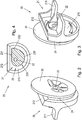
- the fastening unit 25 consists of a contact element 20, a connecting element 23 (see Figure 4 ) and a holding element 21, which are combined to form a prefabricated unit and the fastening unit 25 is thus designed in one piece.
- a passage opening 22 runs through the fastening unit 25, which has a round cross section and extends from the holding element 20 through this, the connecting element 23 and the holding element 21 and is open to the front and rear.
- the contact element 20 represents a circular plate. For manufacturing reasons, cutouts are provided in the plate.
- the passage opening 22 is introduced offset in the contact element 20 to the center thereof.
- the contact element 20 is connected to the holding element 21 via the connecting element 23.
- the holding element 21 has a base plate 210 in the illustrated embodiment.
- the base plate 210 has the shape of a circular segment with a central angle of greater than 180 °. This means that the base plate 210 and thus the holding element 21 have the shape of a circle with a flat 212.
- Handle elements 211 which represent wings in the embodiment shown, extend forward from the base plate 210 of the holding element 21.
- the holding element 21 has a frame which extends forwards from the base plate 210 on the circumference of the base plate 210. In the area of the flattened portion 210 of the holding element 21, the frame is inclined outwards and can thus be used as an insertion aid serve.
- the passage opening 22 is also in the holding element 21 offset from the center of the circle of the flattened circle.
- the connecting element 23 of the fastening unit 25 will now be described with reference to FIG Figure 4 described in more detail.
- the connecting element 23 represents a body with a longitudinal extension between the rear of the holding element 21 and the front of the contact element 20.
- the cross section of the connecting element is designed eccentrically to the passage opening.
- the connecting element 23 thus forms an eccentric.
- the eccentric is a spiral eccentric.
- the circumference of the connecting element 23 thus forms an elevation curve 230 which has the following areas.
- Parallel to the flattened portion 212 of the holding element 21, the upper side of the connecting element 23 is designed as a straight line, which is referred to below as the starting straight line 231.
- the starting straight line 231 At the left end of the starting line 231, that is to say in the counterclockwise direction, the starting line 231 is followed by a spiral curve 233.
- the distance of the circumference of the connecting element 23 from the passage opening increases counterclockwise over the course of the spiral curve 233.
- the spiral curve 233 merges into a final straight line 232.
- the end line 232 and the start line 231 are at an acute angle to one another and the end of the end line 232 is connected to the start of the start line 231 by a rounding.
- the fastening device 2 is, as in Figure 5 shown mounted on the wall W.
- a hole for the fastening element 26 is first drilled in the wall W.
- the fastening unit 25 is then brought in front of the hole in such a way that the passage opening 20 is aligned with the hole.
- the fastening element 26, which is preferably a screw, is then passed through the passage opening 22 and screwed into the hole in the wall W.
- the screw is only tightened to such an extent that rotation of the fastening unit 25 about the fastening element 26 is still possible, but there is no longer any fear of the fastening unit 25 falling down.
- the screw is tightened until the Contact element 20 of the fastening unit 25 abuts the wall W.
- the fastening unit 25 is then aligned such that the flat 212 of the holding element 21 points upward. In this position, the object is connected to the fastening unit 25.
- the receiving area 11 is brought in front of the fastening unit (s) 25 and the receiving openings 110 provided in the receiving area 11 are aligned with the fastening units 25.
- the holding element 21, in a position in which the flat 212 is directed upward, has a vertical dimension H1 in the vertical which is smaller than the diameter of the circular shape of the holding element 21.
- the receiving opening 110 in the receiving area 11 has preferably also a height that corresponds to the dimension H1 or is slightly larger than H1.
- the object can be moved parallel to the wall W to compensate for a lateral offset. If one or both sides of the object, in particular the housing 10 of the extractor hood is too low in this state, the height offset can be compensated for as follows.
- the holding element 21 is also moved in front of the receiving opening 110, that is to say rotated. How from the Figure 6 results, the passage opening 22 is offset to the right to the center of the circle of the holding element 21.
- the fastening unit 25 counterclockwise, the longer part of the base plate 210 is thus rotated downward.
- the flat 212 is tilted to the left, so that the dimension of the holding element 21 increases in the vertical.
- both the upper edge of the receiving opening 110 and the lower edge of the receiving opening 110 are partially covered towards the front by the holding element 21. Falling out or jumping out of the object from the receiving gap 24 of the fastening unit 25 is therefore not to be feared.
- the upper edge of the receiving opening 110 on the elevation curve 230 reaches the final straight line 232 when the fastening unit 25 is rotated further, the maximum elevation of the object is reached. If the fastening unit 25 is turned further counterclockwise, the upper edge of the receiving opening 110 then comes into contact with the starting straight line 231 and the object lowers. The object is lowered by turning the fastening unit 25 clockwise from the end line 232 or an angular position along the spiral curve 233.
- the fastening unit 25 After the user has set the desired height of the object by turning the fastening unit 25 accordingly, he can tighten the fastening element 26, in particular the screw.
- the fastening unit 25 can be held on the handle elements 211 while the screw is being tightened.
- the contact element 20 is pressed against the wall W and the fastening unit 25 is thus clamped between the screw head and the wall W.
- An unwanted twisting of the fastening unit is prevented by this clamping force.
- the highest vertical point of the elevation curve 230 is always perpendicular to the passage opening 22 or at a small horizontal distance to it during the rotation of the fastening unit 25. If the highest vertical point is offset from the passage opening 22, it lies to the right of the passage opening 22.
- the upper edge of the receiving opening 110 rests on this point and the weight of the object thus acts at least partially if necessary, an inherent urge of the fastening unit 25 to rotate about the passage opening 22 is generated.
- This intrinsic urgency can be used positively in a screw with a right-hand thread, which is preferably used as a fastening element 26.
- the present invention is not limited to the illustrated embodiment.
- eccentrics with a circular cross section or an oval cross section can also be used as the connecting element.
- the shape of the holding element or the contact element can also differ from the shape shown. However, it is preferred that the holding element has a shape which, when rotated around the passage opening, causes a change in the vertical dimension of the holding element.
- the present invention thus provides a solution to easily and reliably attach an object, in particular the housing of an extractor hood, to a wall with the possibility of aligning the object without tools.
- height and side offsets can be compensated.
- the object when attaching an object, in particular an extractor hood, to a wall, the object can be aligned with as little effort as possible.
- the front outer dimension, in particular of the holding element in the vertical, and the object, in particular the hood, can no longer slide out of the fastening position by the twisting.
- the fastening unit can be manufactured inexpensively. There are virtually no problems due to fluctuations in material quality.
- the number of elements of the fastening device can be limited to two, namely the fastening unit and a fastening element in the form a screw. This reduces the number of parts and simplifies storage.
- a secure mounting can be achieved in a simple manner during the fastening of the object and after the fastening.
Landscapes
- Engineering & Computer Science (AREA)
- General Engineering & Computer Science (AREA)
- Mechanical Engineering (AREA)
- Clamps And Clips (AREA)
- Hooks, Suction Cups, And Attachment By Adhesive Means (AREA)
Priority Applications (1)
| Application Number | Priority Date | Filing Date | Title |
|---|---|---|---|
| PL15725011T PL3149347T3 (pl) | 2014-06-02 | 2015-05-27 | Urządzenie mocujące do mocowania przedmiotu na ścianie i układ mocowania |
Applications Claiming Priority (2)
| Application Number | Priority Date | Filing Date | Title |
|---|---|---|---|
| DE102014210314.2A DE102014210314A1 (de) | 2014-06-02 | 2014-06-02 | Befestigungsvorrichtung zur Befestigung eines Gegenstandes an einer Wand und Befestigungssystem |
| PCT/EP2015/061630 WO2015185396A1 (de) | 2014-06-02 | 2015-05-27 | Befestigungsvorrichtung zur befestigung eines gegenstandes an einer wand und befestigungssystem |
Publications (2)
| Publication Number | Publication Date |
|---|---|
| EP3149347A1 EP3149347A1 (de) | 2017-04-05 |
| EP3149347B1 true EP3149347B1 (de) | 2019-12-18 |
Family
ID=53268805
Family Applications (1)
| Application Number | Title | Priority Date | Filing Date |
|---|---|---|---|
| EP15725011.9A Active EP3149347B1 (de) | 2014-06-02 | 2015-05-27 | Befestigungsvorrichtung zur befestigung eines gegenstandes an einer wand und befestigungssystem |
Country Status (7)
| Country | Link |
|---|---|
| US (1) | US10634179B2 (pl) |
| EP (1) | EP3149347B1 (pl) |
| CN (1) | CN106415028B (pl) |
| DE (1) | DE102014210314A1 (pl) |
| ES (1) | ES2768717T3 (pl) |
| PL (1) | PL3149347T3 (pl) |
| WO (1) | WO2015185396A1 (pl) |
Families Citing this family (4)
| Publication number | Priority date | Publication date | Assignee | Title |
|---|---|---|---|---|
| CN111456946A (zh) * | 2020-05-15 | 2020-07-28 | 佛山市顺德区美的洗涤电器制造有限公司 | 离心风机及油烟净化装置 |
| EP4085797B1 (de) * | 2021-05-07 | 2025-02-26 | Geberit International AG | Justierbare aufhängevorrichtung |
| CN114396642B (zh) * | 2021-12-30 | 2024-12-17 | 华帝股份有限公司 | 一种油网组件及其吸油烟机 |
| US11867211B1 (en) * | 2023-05-10 | 2024-01-09 | Justin Nelson | Removable plugs for furniture, systems including such plugs, and methods of their use |
Family Cites Families (27)
| Publication number | Priority date | Publication date | Assignee | Title |
|---|---|---|---|---|
| US944725A (en) * | 1909-06-03 | 1909-12-28 | Walton Ferguson Jr | Spike for railway and like uses. |
| US1015890A (en) * | 1911-03-13 | 1912-01-30 | Alfred D Hyde | Fastening device. |
| US1044055A (en) * | 1912-03-13 | 1912-11-12 | Olof M Johnson | Adjusting mechanism. |
| US1213599A (en) * | 1915-10-15 | 1917-01-23 | Charles E W Dow | Fastener. |
| US2074393A (en) * | 1934-03-05 | 1937-03-23 | Alfred J Hixon | Connecter for electric cables and the like |
| US2430613A (en) * | 1945-03-15 | 1947-11-11 | Robert W Hodge | Work holding means |
| US2569914A (en) * | 1948-08-06 | 1951-10-02 | Appleton Electric Co | Cover clamp |
| US2638276A (en) * | 1948-11-10 | 1953-05-12 | Stamm Karl | Rail fastening |
| US2525217A (en) * | 1949-07-06 | 1950-10-10 | Glitsch Engineering Company | Manway clamp |
| US3747168A (en) * | 1971-11-08 | 1973-07-24 | Gen Motors Corp | Clamp assembly |
| DE2328412C3 (de) * | 1973-06-04 | 1975-11-27 | Springfix-Befestigungstechnik Gmbh, 7335 Salach | Befestigungselement |
| US4372015A (en) * | 1981-05-13 | 1983-02-08 | The Boeing Company | Blind hole clamping tool |
| DE3236719C2 (de) * | 1982-10-04 | 1986-07-24 | Karl Lautenschläger KG, Möbelbeschlagfabrik, 6107 Reinheim | Klemmverbinder für Profilleisten |
| US4604079A (en) * | 1984-11-06 | 1986-08-05 | Parrish Kenneth D | Speed changer for electric motor |
| US4659133A (en) * | 1985-09-16 | 1987-04-21 | Durakon Industries, Inc. | Truck bed liner retainer |
| DE4124727C2 (de) * | 1991-07-25 | 1994-01-27 | Salice Arturo Spa | Befestigungselement mit einer dübelartigen Buchse |
| IT1254730B (it) * | 1992-03-23 | 1995-10-10 | Antonio Giovannetti | Dispositivo di ancoraggio,per esempio per componenti di mobili e simili |
| US5964011A (en) * | 1997-09-12 | 1999-10-12 | Newell Operating Company | Adjustable casement window hinge |
| US6997658B2 (en) * | 2003-10-20 | 2006-02-14 | Fly David E | Alignment pin and fastener with bi-directional clamping |
| DE102004041300A1 (de) * | 2004-08-25 | 2006-03-02 | Lautenschläger, Horst | Verstelleinrichtung für Möbelteile |
| CN2764987Y (zh) * | 2004-12-31 | 2006-03-15 | 上海震旦家具有限公司 | 组合式桌具的柱梁连接构件组 |
| US7144184B1 (en) * | 2005-07-29 | 2006-12-05 | Enlight Corporation | Rotary-type fastening structure |
| US7213346B1 (en) * | 2006-02-15 | 2007-05-08 | Gregory Catherine A | Installation tool for horizontal siding boards |
| DE102007021731A1 (de) | 2007-05-09 | 2008-11-13 | BSH Bosch und Siemens Hausgeräte GmbH | Befestigungsvorrichtung zur Befestigung von Gegenständen an einer Grundfläche |
| US8388291B2 (en) * | 2009-05-18 | 2013-03-05 | Donald Scott Rogers | Mat lock pin |
| CN102291953A (zh) * | 2010-06-15 | 2011-12-21 | 鸿富锦精密工业(深圳)有限公司 | 安装电子设备的机柜 |
| DE202012003576U1 (de) * | 2012-04-05 | 2012-08-01 | Raimund Sandhoff | Befestigungsvorrichtung mit einer Klemmvorrichtung für eine Sitzbank- oder Tischunterkonstruktion |
-
2014
- 2014-06-02 DE DE102014210314.2A patent/DE102014210314A1/de not_active Ceased
-
2015
- 2015-05-27 EP EP15725011.9A patent/EP3149347B1/de active Active
- 2015-05-27 CN CN201580029592.2A patent/CN106415028B/zh not_active Expired - Fee Related
- 2015-05-27 WO PCT/EP2015/061630 patent/WO2015185396A1/de not_active Ceased
- 2015-05-27 PL PL15725011T patent/PL3149347T3/pl unknown
- 2015-05-27 ES ES15725011T patent/ES2768717T3/es active Active
- 2015-05-27 US US15/310,453 patent/US10634179B2/en not_active Expired - Fee Related
Non-Patent Citations (1)
| Title |
|---|
| None * |
Also Published As
| Publication number | Publication date |
|---|---|
| ES2768717T3 (es) | 2020-06-23 |
| CN106415028A (zh) | 2017-02-15 |
| WO2015185396A1 (de) | 2015-12-10 |
| US10634179B2 (en) | 2020-04-28 |
| PL3149347T3 (pl) | 2020-06-01 |
| DE102014210314A1 (de) | 2015-12-03 |
| CN106415028B (zh) | 2020-03-10 |
| US20170089381A1 (en) | 2017-03-30 |
| EP3149347A1 (de) | 2017-04-05 |
Similar Documents
| Publication | Publication Date | Title |
|---|---|---|
| EP2742199B1 (de) | Befestigungsanordnung zur befestigung eines bauteils an einer nut eines fensters, einer tür oder dergleichen | |
| EP2944436B1 (de) | Tragegestell mit klapperfrei verriegelbaren tragelementen | |
| DE102007013438B4 (de) | Blumenkastenhalterung mit einer Klemmvorrichtung | |
| EP3149347B1 (de) | Befestigungsvorrichtung zur befestigung eines gegenstandes an einer wand und befestigungssystem | |
| EP3649353A1 (de) | Befestigungsanordnung | |
| EP3121460A1 (de) | Vorrichtung zum verbinden zweier moebelteile | |
| DE1928490A1 (de) | Schlossmutteranordnung | |
| EP3214403A1 (de) | Haltevorrichtung für ein lasergerät | |
| DE3690170C2 (pl) | ||
| DE19912474A1 (de) | Befestigungsanordnung für die Anbringung eines Bauteils an einer C-förmigen Halteschiene | |
| DE2522393C2 (de) | In einer Aufnahmebohrung verankerbares Beschlagteil | |
| EP2378209B1 (de) | Dunstabzugshaube | |
| DE102014009257B4 (de) | Exzenterelement und Verfahren zum Einstellen einer Relativposition eines Anbauteils | |
| EP3332133A1 (de) | Käfigmutter | |
| DE202015008989U1 (de) | Befestigungssystem für einen Toilettensitz, Käfig, Käfigmutter und Anordnung | |
| DE102012011364B3 (de) | Klemmvorrichtung | |
| EP3922869B1 (de) | Anschlussvorrichtung zum befestigen an einem hohlprofil sowie stabilisierungsset und stabilisierungsanordnung | |
| EP0621926A1 (de) | Anlaufleiste für eine schutzhaube an holzfräsmaschinen. | |
| DE102006018835B4 (de) | Schraube für eine Spannvorrichtung, Spannvorrichtung mit einer solchen Schraube und Verfahren zum Festspannen eines Werkstücks | |
| DE102009022939A1 (de) | Kraftfahrzeug mit einer höheneinstellbaren Frontklappe | |
| DE2034993C3 (de) | Schneidwerkzeug für spanabhebende Bearbeitung | |
| EP4438839B1 (de) | Klemmeinheit zur befestigung eines beschlagteils in einer beschlagnut eines fensters oder einer tür | |
| EP1859115A1 (de) | Beschlag zur befestigung in einer hinterschnittenen nut eines metall- oder kunststoffprofils | |
| DE102006035294B4 (de) | Schraube für eine Spannvorrichtung, Spannvorrichtung mit einer solchen Schraube und Verfahren zum Festspannen eines Werkstücks | |
| DE19904413C2 (de) | Einsatzteil zur Führung eines stiftförmigen Befestigungselements |
Legal Events
| Date | Code | Title | Description |
|---|---|---|---|
| STAA | Information on the status of an ep patent application or granted ep patent |
Free format text: STATUS: THE INTERNATIONAL PUBLICATION HAS BEEN MADE |
|
| PUAI | Public reference made under article 153(3) epc to a published international application that has entered the european phase |
Free format text: ORIGINAL CODE: 0009012 |
|
| STAA | Information on the status of an ep patent application or granted ep patent |
Free format text: STATUS: REQUEST FOR EXAMINATION WAS MADE |
|
| 17P | Request for examination filed |
Effective date: 20170102 |
|
| AK | Designated contracting states |
Kind code of ref document: A1 Designated state(s): AL AT BE BG CH CY CZ DE DK EE ES FI FR GB GR HR HU IE IS IT LI LT LU LV MC MK MT NL NO PL PT RO RS SE SI SK SM TR |
|
| AX | Request for extension of the european patent |
Extension state: BA ME |
|
| DAV | Request for validation of the european patent (deleted) | ||
| DAX | Request for extension of the european patent (deleted) | ||
| REG | Reference to a national code |
Ref country code: DE Ref legal event code: R079 Ref document number: 502015011261 Country of ref document: DE Free format text: PREVIOUS MAIN CLASS: F16B0012140000 Ipc: F16B0005020000 |
|
| RIC1 | Information provided on ipc code assigned before grant |
Ipc: F16B 12/20 20060101ALI20190628BHEP Ipc: F16B 43/00 20060101ALI20190628BHEP Ipc: F16B 5/02 20060101AFI20190628BHEP Ipc: F16B 12/14 20060101ALI20190628BHEP |
|
| GRAP | Despatch of communication of intention to grant a patent |
Free format text: ORIGINAL CODE: EPIDOSNIGR1 |
|
| STAA | Information on the status of an ep patent application or granted ep patent |
Free format text: STATUS: GRANT OF PATENT IS INTENDED |
|
| INTG | Intention to grant announced |
Effective date: 20190809 |
|
| GRAS | Grant fee paid |
Free format text: ORIGINAL CODE: EPIDOSNIGR3 |
|
| GRAA | (expected) grant |
Free format text: ORIGINAL CODE: 0009210 |
|
| STAA | Information on the status of an ep patent application or granted ep patent |
Free format text: STATUS: THE PATENT HAS BEEN GRANTED |
|
| AK | Designated contracting states |
Kind code of ref document: B1 Designated state(s): AL AT BE BG CH CY CZ DE DK EE ES FI FR GB GR HR HU IE IS IT LI LT LU LV MC MK MT NL NO PL PT RO RS SE SI SK SM TR |
|
| REG | Reference to a national code |
Ref country code: CH Ref legal event code: EP |
|
| REG | Reference to a national code |
Ref country code: DE Ref legal event code: R096 Ref document number: 502015011261 Country of ref document: DE |
|
| REG | Reference to a national code |
Ref country code: IE Ref legal event code: FG4D Free format text: LANGUAGE OF EP DOCUMENT: GERMAN |
|
| REG | Reference to a national code |
Ref country code: AT Ref legal event code: REF Ref document number: 1214917 Country of ref document: AT Kind code of ref document: T Effective date: 20200115 |
|
| REG | Reference to a national code |
Ref country code: NL Ref legal event code: MP Effective date: 20191218 |
|
| PG25 | Lapsed in a contracting state [announced via postgrant information from national office to epo] |
Ref country code: FI Free format text: LAPSE BECAUSE OF FAILURE TO SUBMIT A TRANSLATION OF THE DESCRIPTION OR TO PAY THE FEE WITHIN THE PRESCRIBED TIME-LIMIT Effective date: 20191218 Ref country code: BG Free format text: LAPSE BECAUSE OF FAILURE TO SUBMIT A TRANSLATION OF THE DESCRIPTION OR TO PAY THE FEE WITHIN THE PRESCRIBED TIME-LIMIT Effective date: 20200318 Ref country code: LT Free format text: LAPSE BECAUSE OF FAILURE TO SUBMIT A TRANSLATION OF THE DESCRIPTION OR TO PAY THE FEE WITHIN THE PRESCRIBED TIME-LIMIT Effective date: 20191218 Ref country code: NO Free format text: LAPSE BECAUSE OF FAILURE TO SUBMIT A TRANSLATION OF THE DESCRIPTION OR TO PAY THE FEE WITHIN THE PRESCRIBED TIME-LIMIT Effective date: 20200318 Ref country code: GR Free format text: LAPSE BECAUSE OF FAILURE TO SUBMIT A TRANSLATION OF THE DESCRIPTION OR TO PAY THE FEE WITHIN THE PRESCRIBED TIME-LIMIT Effective date: 20200319 Ref country code: LV Free format text: LAPSE BECAUSE OF FAILURE TO SUBMIT A TRANSLATION OF THE DESCRIPTION OR TO PAY THE FEE WITHIN THE PRESCRIBED TIME-LIMIT Effective date: 20191218 Ref country code: SE Free format text: LAPSE BECAUSE OF FAILURE TO SUBMIT A TRANSLATION OF THE DESCRIPTION OR TO PAY THE FEE WITHIN THE PRESCRIBED TIME-LIMIT Effective date: 20191218 |
|
| REG | Reference to a national code |
Ref country code: LT Ref legal event code: MG4D |
|
| PG25 | Lapsed in a contracting state [announced via postgrant information from national office to epo] |
Ref country code: RS Free format text: LAPSE BECAUSE OF FAILURE TO SUBMIT A TRANSLATION OF THE DESCRIPTION OR TO PAY THE FEE WITHIN THE PRESCRIBED TIME-LIMIT Effective date: 20191218 Ref country code: HR Free format text: LAPSE BECAUSE OF FAILURE TO SUBMIT A TRANSLATION OF THE DESCRIPTION OR TO PAY THE FEE WITHIN THE PRESCRIBED TIME-LIMIT Effective date: 20191218 |
|
| REG | Reference to a national code |
Ref country code: ES Ref legal event code: FG2A Ref document number: 2768717 Country of ref document: ES Kind code of ref document: T3 Effective date: 20200623 |
|
| PG25 | Lapsed in a contracting state [announced via postgrant information from national office to epo] |
Ref country code: AL Free format text: LAPSE BECAUSE OF FAILURE TO SUBMIT A TRANSLATION OF THE DESCRIPTION OR TO PAY THE FEE WITHIN THE PRESCRIBED TIME-LIMIT Effective date: 20191218 |
|
| PG25 | Lapsed in a contracting state [announced via postgrant information from national office to epo] |
Ref country code: EE Free format text: LAPSE BECAUSE OF FAILURE TO SUBMIT A TRANSLATION OF THE DESCRIPTION OR TO PAY THE FEE WITHIN THE PRESCRIBED TIME-LIMIT Effective date: 20191218 Ref country code: RO Free format text: LAPSE BECAUSE OF FAILURE TO SUBMIT A TRANSLATION OF THE DESCRIPTION OR TO PAY THE FEE WITHIN THE PRESCRIBED TIME-LIMIT Effective date: 20191218 Ref country code: PT Free format text: LAPSE BECAUSE OF FAILURE TO SUBMIT A TRANSLATION OF THE DESCRIPTION OR TO PAY THE FEE WITHIN THE PRESCRIBED TIME-LIMIT Effective date: 20200513 Ref country code: NL Free format text: LAPSE BECAUSE OF FAILURE TO SUBMIT A TRANSLATION OF THE DESCRIPTION OR TO PAY THE FEE WITHIN THE PRESCRIBED TIME-LIMIT Effective date: 20191218 Ref country code: CZ Free format text: LAPSE BECAUSE OF FAILURE TO SUBMIT A TRANSLATION OF THE DESCRIPTION OR TO PAY THE FEE WITHIN THE PRESCRIBED TIME-LIMIT Effective date: 20191218 |
|
| PG25 | Lapsed in a contracting state [announced via postgrant information from national office to epo] |
Ref country code: IS Free format text: LAPSE BECAUSE OF FAILURE TO SUBMIT A TRANSLATION OF THE DESCRIPTION OR TO PAY THE FEE WITHIN THE PRESCRIBED TIME-LIMIT Effective date: 20200418 Ref country code: SM Free format text: LAPSE BECAUSE OF FAILURE TO SUBMIT A TRANSLATION OF THE DESCRIPTION OR TO PAY THE FEE WITHIN THE PRESCRIBED TIME-LIMIT Effective date: 20191218 Ref country code: SK Free format text: LAPSE BECAUSE OF FAILURE TO SUBMIT A TRANSLATION OF THE DESCRIPTION OR TO PAY THE FEE WITHIN THE PRESCRIBED TIME-LIMIT Effective date: 20191218 |
|
| REG | Reference to a national code |
Ref country code: DE Ref legal event code: R097 Ref document number: 502015011261 Country of ref document: DE |
|
| PLBE | No opposition filed within time limit |
Free format text: ORIGINAL CODE: 0009261 |
|
| STAA | Information on the status of an ep patent application or granted ep patent |
Free format text: STATUS: NO OPPOSITION FILED WITHIN TIME LIMIT |
|
| PG25 | Lapsed in a contracting state [announced via postgrant information from national office to epo] |
Ref country code: DK Free format text: LAPSE BECAUSE OF FAILURE TO SUBMIT A TRANSLATION OF THE DESCRIPTION OR TO PAY THE FEE WITHIN THE PRESCRIBED TIME-LIMIT Effective date: 20191218 |
|
| 26N | No opposition filed |
Effective date: 20200921 |
|
| PG25 | Lapsed in a contracting state [announced via postgrant information from national office to epo] |
Ref country code: SI Free format text: LAPSE BECAUSE OF FAILURE TO SUBMIT A TRANSLATION OF THE DESCRIPTION OR TO PAY THE FEE WITHIN THE PRESCRIBED TIME-LIMIT Effective date: 20191218 |
|
| PG25 | Lapsed in a contracting state [announced via postgrant information from national office to epo] |
Ref country code: CH Free format text: LAPSE BECAUSE OF NON-PAYMENT OF DUE FEES Effective date: 20200531 Ref country code: MC Free format text: LAPSE BECAUSE OF FAILURE TO SUBMIT A TRANSLATION OF THE DESCRIPTION OR TO PAY THE FEE WITHIN THE PRESCRIBED TIME-LIMIT Effective date: 20191218 Ref country code: LI Free format text: LAPSE BECAUSE OF NON-PAYMENT OF DUE FEES Effective date: 20200531 |
|
| PG25 | Lapsed in a contracting state [announced via postgrant information from national office to epo] |
Ref country code: LU Free format text: LAPSE BECAUSE OF NON-PAYMENT OF DUE FEES Effective date: 20200527 |
|
| PG25 | Lapsed in a contracting state [announced via postgrant information from national office to epo] |
Ref country code: FR Free format text: LAPSE BECAUSE OF NON-PAYMENT OF DUE FEES Effective date: 20200531 Ref country code: IE Free format text: LAPSE BECAUSE OF NON-PAYMENT OF DUE FEES Effective date: 20200527 |
|
| REG | Reference to a national code |
Ref country code: AT Ref legal event code: MM01 Ref document number: 1214917 Country of ref document: AT Kind code of ref document: T Effective date: 20200527 |
|
| PG25 | Lapsed in a contracting state [announced via postgrant information from national office to epo] |
Ref country code: AT Free format text: LAPSE BECAUSE OF NON-PAYMENT OF DUE FEES Effective date: 20200527 |
|
| PG25 | Lapsed in a contracting state [announced via postgrant information from national office to epo] |
Ref country code: MT Free format text: LAPSE BECAUSE OF FAILURE TO SUBMIT A TRANSLATION OF THE DESCRIPTION OR TO PAY THE FEE WITHIN THE PRESCRIBED TIME-LIMIT Effective date: 20191218 Ref country code: CY Free format text: LAPSE BECAUSE OF FAILURE TO SUBMIT A TRANSLATION OF THE DESCRIPTION OR TO PAY THE FEE WITHIN THE PRESCRIBED TIME-LIMIT Effective date: 20191218 |
|
| PG25 | Lapsed in a contracting state [announced via postgrant information from national office to epo] |
Ref country code: MK Free format text: LAPSE BECAUSE OF FAILURE TO SUBMIT A TRANSLATION OF THE DESCRIPTION OR TO PAY THE FEE WITHIN THE PRESCRIBED TIME-LIMIT Effective date: 20191218 |
|
| PGFP | Annual fee paid to national office [announced via postgrant information from national office to epo] |
Ref country code: ES Payment date: 20230621 Year of fee payment: 9 |
|
| PGFP | Annual fee paid to national office [announced via postgrant information from national office to epo] |
Ref country code: PL Payment date: 20230512 Year of fee payment: 9 |
|
| PGFP | Annual fee paid to national office [announced via postgrant information from national office to epo] |
Ref country code: BE Payment date: 20230517 Year of fee payment: 9 |
|
| PGFP | Annual fee paid to national office [announced via postgrant information from national office to epo] |
Ref country code: GB Payment date: 20230522 Year of fee payment: 9 |
|
| GBPC | Gb: european patent ceased through non-payment of renewal fee |
Effective date: 20240527 |
|
| REG | Reference to a national code |
Ref country code: BE Ref legal event code: MM Effective date: 20240531 |
|
| PG25 | Lapsed in a contracting state [announced via postgrant information from national office to epo] |
Ref country code: BE Free format text: LAPSE BECAUSE OF NON-PAYMENT OF DUE FEES Effective date: 20240531 |
|
| PG25 | Lapsed in a contracting state [announced via postgrant information from national office to epo] |
Ref country code: GB Free format text: LAPSE BECAUSE OF NON-PAYMENT OF DUE FEES Effective date: 20240527 |
|
| REG | Reference to a national code |
Ref country code: ES Ref legal event code: FD2A Effective date: 20250704 |
|
| PG25 | Lapsed in a contracting state [announced via postgrant information from national office to epo] |
Ref country code: PL Free format text: LAPSE BECAUSE OF NON-PAYMENT OF DUE FEES Effective date: 20240527 |
|
| PGFP | Annual fee paid to national office [announced via postgrant information from national office to epo] |
Ref country code: DE Payment date: 20250531 Year of fee payment: 11 |
|
| PG25 | Lapsed in a contracting state [announced via postgrant information from national office to epo] |
Ref country code: ES Free format text: LAPSE BECAUSE OF NON-PAYMENT OF DUE FEES Effective date: 20240528 |
|
| PGFP | Annual fee paid to national office [announced via postgrant information from national office to epo] |
Ref country code: IT Payment date: 20250530 Year of fee payment: 11 |
|
| PGFP | Annual fee paid to national office [announced via postgrant information from national office to epo] |
Ref country code: TR Payment date: 20250520 Year of fee payment: 11 |