EP3149345B1 - Method of joining two objects - Google Patents
Method of joining two objects Download PDFInfo
- Publication number
- EP3149345B1 EP3149345B1 EP15725033.3A EP15725033A EP3149345B1 EP 3149345 B1 EP3149345 B1 EP 3149345B1 EP 15725033 A EP15725033 A EP 15725033A EP 3149345 B1 EP3149345 B1 EP 3149345B1
- Authority
- EP
- European Patent Office
- Prior art keywords
- opening
- insert portion
- interference fit
- objects
- anchoring
- Prior art date
- Legal status (The legal status is an assumption and is not a legal conclusion. Google has not performed a legal analysis and makes no representation as to the accuracy of the status listed.)
- Active
Links
- 238000000034 method Methods 0.000 title claims description 73
- 238000005304 joining Methods 0.000 title claims description 8
- 239000000463 material Substances 0.000 claims description 108
- 238000004873 anchoring Methods 0.000 claims description 69
- 238000010008 shearing Methods 0.000 claims description 24
- 229920001169 thermoplastic Polymers 0.000 claims description 20
- 239000004416 thermosoftening plastic Substances 0.000 claims description 18
- 238000003780 insertion Methods 0.000 claims description 15
- 230000037431 insertion Effects 0.000 claims description 15
- 230000008569 process Effects 0.000 claims description 12
- 239000007787 solid Substances 0.000 claims description 9
- 239000002023 wood Substances 0.000 claims description 8
- 239000011093 chipboard Substances 0.000 claims description 7
- 238000004519 manufacturing process Methods 0.000 claims description 7
- 239000000835 fiber Substances 0.000 claims description 3
- 239000011120 plywood Substances 0.000 claims description 3
- 238000012546 transfer Methods 0.000 claims description 3
- 239000011111 cardboard Substances 0.000 claims description 2
- 239000012815 thermoplastic material Substances 0.000 description 42
- 238000002844 melting Methods 0.000 description 12
- 230000008018 melting Effects 0.000 description 12
- 239000011148 porous material Substances 0.000 description 9
- 239000006260 foam Substances 0.000 description 6
- 229920000642 polymer Polymers 0.000 description 6
- 238000003825 pressing Methods 0.000 description 6
- 239000011343 solid material Substances 0.000 description 6
- 230000006835 compression Effects 0.000 description 5
- 238000007906 compression Methods 0.000 description 5
- 239000002657 fibrous material Substances 0.000 description 5
- 230000035515 penetration Effects 0.000 description 5
- -1 polyethylene Polymers 0.000 description 5
- 239000002131 composite material Substances 0.000 description 4
- 238000010586 diagram Methods 0.000 description 4
- 230000009477 glass transition Effects 0.000 description 4
- 229920003023 plastic Polymers 0.000 description 4
- 239000004033 plastic Substances 0.000 description 4
- 229920002647 polyamide Polymers 0.000 description 4
- 239000004952 Polyamide Substances 0.000 description 3
- 230000004323 axial length Effects 0.000 description 3
- 239000000919 ceramic Substances 0.000 description 3
- 238000000576 coating method Methods 0.000 description 3
- 238000006073 displacement reaction Methods 0.000 description 3
- 238000005553 drilling Methods 0.000 description 3
- 230000000694 effects Effects 0.000 description 3
- 230000009969 flowable effect Effects 0.000 description 3
- 238000010438 heat treatment Methods 0.000 description 3
- 238000007373 indentation Methods 0.000 description 3
- 239000002245 particle Substances 0.000 description 3
- 239000002861 polymer material Substances 0.000 description 3
- 230000009467 reduction Effects 0.000 description 3
- 238000007711 solidification Methods 0.000 description 3
- 239000004697 Polyetherimide Substances 0.000 description 2
- 230000009471 action Effects 0.000 description 2
- 229910010293 ceramic material Inorganic materials 0.000 description 2
- 239000011248 coating agent Substances 0.000 description 2
- 239000000470 constituent Substances 0.000 description 2
- 229920001577 copolymer Polymers 0.000 description 2
- 238000005336 cracking Methods 0.000 description 2
- 238000013461 design Methods 0.000 description 2
- 239000007788 liquid Substances 0.000 description 2
- 230000014759 maintenance of location Effects 0.000 description 2
- 239000002184 metal Substances 0.000 description 2
- 239000007769 metal material Substances 0.000 description 2
- 239000000203 mixture Substances 0.000 description 2
- 230000000149 penetrating effect Effects 0.000 description 2
- 239000012071 phase Substances 0.000 description 2
- 229920001643 poly(ether ketone) Polymers 0.000 description 2
- 229920002492 poly(sulfone) Polymers 0.000 description 2
- 229920001601 polyetherimide Polymers 0.000 description 2
- 229920000069 polyphenylene sulfide Polymers 0.000 description 2
- 230000002829 reductive effect Effects 0.000 description 2
- 230000000717 retained effect Effects 0.000 description 2
- 230000002441 reversible effect Effects 0.000 description 2
- 238000004904 shortening Methods 0.000 description 2
- 239000004616 structural foam Substances 0.000 description 2
- 229920000638 styrene acrylonitrile Polymers 0.000 description 2
- 229920001187 thermosetting polymer Polymers 0.000 description 2
- 229920000106 Liquid crystal polymer Polymers 0.000 description 1
- 208000029154 Narrow face Diseases 0.000 description 1
- 229920000571 Nylon 11 Polymers 0.000 description 1
- 229920000299 Nylon 12 Polymers 0.000 description 1
- 229920002292 Nylon 6 Polymers 0.000 description 1
- 229920002302 Nylon 6,6 Polymers 0.000 description 1
- 229930040373 Paraformaldehyde Natural products 0.000 description 1
- 239000004698 Polyethylene Substances 0.000 description 1
- 239000004743 Polypropylene Substances 0.000 description 1
- 239000004793 Polystyrene Substances 0.000 description 1
- 239000004676 acrylonitrile butadiene styrene Substances 0.000 description 1
- 239000000853 adhesive Substances 0.000 description 1
- 230000001070 adhesive effect Effects 0.000 description 1
- 229920006125 amorphous polymer Polymers 0.000 description 1
- 238000013459 approach Methods 0.000 description 1
- 230000008901 benefit Effects 0.000 description 1
- 230000015572 biosynthetic process Effects 0.000 description 1
- 210000000988 bone and bone Anatomy 0.000 description 1
- 150000004649 carbonic acid derivatives Chemical class 0.000 description 1
- 230000008859 change Effects 0.000 description 1
- 239000011456 concrete brick Substances 0.000 description 1
- 238000010276 construction Methods 0.000 description 1
- 238000004132 cross linking Methods 0.000 description 1
- 238000002425 crystallisation Methods 0.000 description 1
- 230000008025 crystallization Effects 0.000 description 1
- 238000005520 cutting process Methods 0.000 description 1
- 230000003247 decreasing effect Effects 0.000 description 1
- 230000001419 dependent effect Effects 0.000 description 1
- 230000009977 dual effect Effects 0.000 description 1
- 239000013013 elastic material Substances 0.000 description 1
- 229920001971 elastomer Polymers 0.000 description 1
- 239000000806 elastomer Substances 0.000 description 1
- 238000002474 experimental method Methods 0.000 description 1
- 239000000945 filler Substances 0.000 description 1
- 239000011521 glass Substances 0.000 description 1
- 239000003365 glass fiber Substances 0.000 description 1
- 239000011796 hollow space material Substances 0.000 description 1
- 230000002706 hydrostatic effect Effects 0.000 description 1
- 230000001771 impaired effect Effects 0.000 description 1
- 230000001939 inductive effect Effects 0.000 description 1
- 230000002452 interceptive effect Effects 0.000 description 1
- 230000000670 limiting effect Effects 0.000 description 1
- 239000007791 liquid phase Substances 0.000 description 1
- 238000003754 machining Methods 0.000 description 1
- 238000011089 mechanical engineering Methods 0.000 description 1
- 238000002156 mixing Methods 0.000 description 1
- 230000010355 oscillation Effects 0.000 description 1
- 230000036961 partial effect Effects 0.000 description 1
- 239000004417 polycarbonate Substances 0.000 description 1
- 229920000515 polycarbonate Polymers 0.000 description 1
- 229920001692 polycarbonate urethane Polymers 0.000 description 1
- 229920000728 polyester Polymers 0.000 description 1
- 229920000573 polyethylene Polymers 0.000 description 1
- 229920006324 polyoxymethylene Polymers 0.000 description 1
- 229920001155 polypropylene Polymers 0.000 description 1
- 229920002223 polystyrene Polymers 0.000 description 1
- 229920000915 polyvinyl chloride Polymers 0.000 description 1
- 239000004800 polyvinyl chloride Substances 0.000 description 1
- 239000005373 porous glass Substances 0.000 description 1
- 239000000047 product Substances 0.000 description 1
- SCUZVMOVTVSBLE-UHFFFAOYSA-N prop-2-enenitrile;styrene Chemical compound C=CC#N.C=CC1=CC=CC=C1 SCUZVMOVTVSBLE-UHFFFAOYSA-N 0.000 description 1
- 239000007779 soft material Substances 0.000 description 1
- 239000007790 solid phase Substances 0.000 description 1
- 238000003860 storage Methods 0.000 description 1
- 239000013589 supplement Substances 0.000 description 1
- 239000004753 textile Substances 0.000 description 1
- 238000003466 welding Methods 0.000 description 1
Images

Classifications
-
- B—PERFORMING OPERATIONS; TRANSPORTING
- B29—WORKING OF PLASTICS; WORKING OF SUBSTANCES IN A PLASTIC STATE IN GENERAL
- B29C—SHAPING OR JOINING OF PLASTICS; SHAPING OF MATERIAL IN A PLASTIC STATE, NOT OTHERWISE PROVIDED FOR; AFTER-TREATMENT OF THE SHAPED PRODUCTS, e.g. REPAIRING
- B29C65/00—Joining or sealing of preformed parts, e.g. welding of plastics materials; Apparatus therefor
- B29C65/72—Joining or sealing of preformed parts, e.g. welding of plastics materials; Apparatus therefor by combined operations or combined techniques, e.g. welding and stitching
-
- F—MECHANICAL ENGINEERING; LIGHTING; HEATING; WEAPONS; BLASTING
- F16—ENGINEERING ELEMENTS AND UNITS; GENERAL MEASURES FOR PRODUCING AND MAINTAINING EFFECTIVE FUNCTIONING OF MACHINES OR INSTALLATIONS; THERMAL INSULATION IN GENERAL
- F16B—DEVICES FOR FASTENING OR SECURING CONSTRUCTIONAL ELEMENTS OR MACHINE PARTS TOGETHER, e.g. NAILS, BOLTS, CIRCLIPS, CLAMPS, CLIPS OR WEDGES; JOINTS OR JOINTING
- F16B3/00—Key-type connections; Keys
- F16B3/005—Key-type connections; Keys the key being formed by solidification of injected material
-
- B—PERFORMING OPERATIONS; TRANSPORTING
- B29—WORKING OF PLASTICS; WORKING OF SUBSTANCES IN A PLASTIC STATE IN GENERAL
- B29C—SHAPING OR JOINING OF PLASTICS; SHAPING OF MATERIAL IN A PLASTIC STATE, NOT OTHERWISE PROVIDED FOR; AFTER-TREATMENT OF THE SHAPED PRODUCTS, e.g. REPAIRING
- B29C65/00—Joining or sealing of preformed parts, e.g. welding of plastics materials; Apparatus therefor
- B29C65/02—Joining or sealing of preformed parts, e.g. welding of plastics materials; Apparatus therefor by heating, with or without pressure
- B29C65/08—Joining or sealing of preformed parts, e.g. welding of plastics materials; Apparatus therefor by heating, with or without pressure using ultrasonic vibrations
-
- B—PERFORMING OPERATIONS; TRANSPORTING
- B29—WORKING OF PLASTICS; WORKING OF SUBSTANCES IN A PLASTIC STATE IN GENERAL
- B29C—SHAPING OR JOINING OF PLASTICS; SHAPING OF MATERIAL IN A PLASTIC STATE, NOT OTHERWISE PROVIDED FOR; AFTER-TREATMENT OF THE SHAPED PRODUCTS, e.g. REPAIRING
- B29C65/00—Joining or sealing of preformed parts, e.g. welding of plastics materials; Apparatus therefor
- B29C65/48—Joining or sealing of preformed parts, e.g. welding of plastics materials; Apparatus therefor using adhesives, i.e. using supplementary joining material; solvent bonding
- B29C65/4805—Joining or sealing of preformed parts, e.g. welding of plastics materials; Apparatus therefor using adhesives, i.e. using supplementary joining material; solvent bonding characterised by the type of adhesives
- B29C65/481—Non-reactive adhesives, e.g. physically hardening adhesives
- B29C65/4815—Hot melt adhesives, e.g. thermoplastic adhesives
-
- B—PERFORMING OPERATIONS; TRANSPORTING
- B29—WORKING OF PLASTICS; WORKING OF SUBSTANCES IN A PLASTIC STATE IN GENERAL
- B29C—SHAPING OR JOINING OF PLASTICS; SHAPING OF MATERIAL IN A PLASTIC STATE, NOT OTHERWISE PROVIDED FOR; AFTER-TREATMENT OF THE SHAPED PRODUCTS, e.g. REPAIRING
- B29C65/00—Joining or sealing of preformed parts, e.g. welding of plastics materials; Apparatus therefor
- B29C65/48—Joining or sealing of preformed parts, e.g. welding of plastics materials; Apparatus therefor using adhesives, i.e. using supplementary joining material; solvent bonding
- B29C65/50—Joining or sealing of preformed parts, e.g. welding of plastics materials; Apparatus therefor using adhesives, i.e. using supplementary joining material; solvent bonding using adhesive tape, e.g. thermoplastic tape; using threads or the like
- B29C65/5057—Joining or sealing of preformed parts, e.g. welding of plastics materials; Apparatus therefor using adhesives, i.e. using supplementary joining material; solvent bonding using adhesive tape, e.g. thermoplastic tape; using threads or the like positioned between the surfaces to be joined
-
- B—PERFORMING OPERATIONS; TRANSPORTING
- B29—WORKING OF PLASTICS; WORKING OF SUBSTANCES IN A PLASTIC STATE IN GENERAL
- B29C—SHAPING OR JOINING OF PLASTICS; SHAPING OF MATERIAL IN A PLASTIC STATE, NOT OTHERWISE PROVIDED FOR; AFTER-TREATMENT OF THE SHAPED PRODUCTS, e.g. REPAIRING
- B29C65/00—Joining or sealing of preformed parts, e.g. welding of plastics materials; Apparatus therefor
- B29C65/56—Joining or sealing of preformed parts, e.g. welding of plastics materials; Apparatus therefor using mechanical means or mechanical connections, e.g. form-fits
- B29C65/562—Joining or sealing of preformed parts, e.g. welding of plastics materials; Apparatus therefor using mechanical means or mechanical connections, e.g. form-fits using extra joining elements, i.e. which are not integral with the parts to be joined
- B29C65/564—Joining or sealing of preformed parts, e.g. welding of plastics materials; Apparatus therefor using mechanical means or mechanical connections, e.g. form-fits using extra joining elements, i.e. which are not integral with the parts to be joined hidden in the joint, e.g. dowels or Z-pins
-
- B—PERFORMING OPERATIONS; TRANSPORTING
- B29—WORKING OF PLASTICS; WORKING OF SUBSTANCES IN A PLASTIC STATE IN GENERAL
- B29C—SHAPING OR JOINING OF PLASTICS; SHAPING OF MATERIAL IN A PLASTIC STATE, NOT OTHERWISE PROVIDED FOR; AFTER-TREATMENT OF THE SHAPED PRODUCTS, e.g. REPAIRING
- B29C65/00—Joining or sealing of preformed parts, e.g. welding of plastics materials; Apparatus therefor
- B29C65/56—Joining or sealing of preformed parts, e.g. welding of plastics materials; Apparatus therefor using mechanical means or mechanical connections, e.g. form-fits
- B29C65/565—Joining or sealing of preformed parts, e.g. welding of plastics materials; Apparatus therefor using mechanical means or mechanical connections, e.g. form-fits involving interference fits, e.g. force-fits or press-fits
-
- B—PERFORMING OPERATIONS; TRANSPORTING
- B29—WORKING OF PLASTICS; WORKING OF SUBSTANCES IN A PLASTIC STATE IN GENERAL
- B29C—SHAPING OR JOINING OF PLASTICS; SHAPING OF MATERIAL IN A PLASTIC STATE, NOT OTHERWISE PROVIDED FOR; AFTER-TREATMENT OF THE SHAPED PRODUCTS, e.g. REPAIRING
- B29C65/00—Joining or sealing of preformed parts, e.g. welding of plastics materials; Apparatus therefor
- B29C65/56—Joining or sealing of preformed parts, e.g. welding of plastics materials; Apparatus therefor using mechanical means or mechanical connections, e.g. form-fits
- B29C65/60—Riveting or staking
- B29C65/601—Riveting or staking using extra riveting elements, i.e. the rivets being non-integral with the parts to be joined
- B29C65/603—Riveting or staking using extra riveting elements, i.e. the rivets being non-integral with the parts to be joined the rivets being pushed in blind holes
- B29C65/604—Riveting or staking using extra riveting elements, i.e. the rivets being non-integral with the parts to be joined the rivets being pushed in blind holes in both parts
-
- B—PERFORMING OPERATIONS; TRANSPORTING
- B29—WORKING OF PLASTICS; WORKING OF SUBSTANCES IN A PLASTIC STATE IN GENERAL
- B29C—SHAPING OR JOINING OF PLASTICS; SHAPING OF MATERIAL IN A PLASTIC STATE, NOT OTHERWISE PROVIDED FOR; AFTER-TREATMENT OF THE SHAPED PRODUCTS, e.g. REPAIRING
- B29C65/00—Joining or sealing of preformed parts, e.g. welding of plastics materials; Apparatus therefor
- B29C65/56—Joining or sealing of preformed parts, e.g. welding of plastics materials; Apparatus therefor using mechanical means or mechanical connections, e.g. form-fits
- B29C65/60—Riveting or staking
- B29C65/606—Riveting or staking the rivets being integral with one of the parts to be joined, i.e. staking
- B29C65/608—Riveting or staking the rivets being integral with one of the parts to be joined, i.e. staking the integral rivets being pushed in blind holes
-
- B—PERFORMING OPERATIONS; TRANSPORTING
- B29—WORKING OF PLASTICS; WORKING OF SUBSTANCES IN A PLASTIC STATE IN GENERAL
- B29C—SHAPING OR JOINING OF PLASTICS; SHAPING OF MATERIAL IN A PLASTIC STATE, NOT OTHERWISE PROVIDED FOR; AFTER-TREATMENT OF THE SHAPED PRODUCTS, e.g. REPAIRING
- B29C65/00—Joining or sealing of preformed parts, e.g. welding of plastics materials; Apparatus therefor
- B29C65/56—Joining or sealing of preformed parts, e.g. welding of plastics materials; Apparatus therefor using mechanical means or mechanical connections, e.g. form-fits
- B29C65/64—Joining a non-plastics element to a plastics element, e.g. by force
- B29C65/645—Joining a non-plastics element to a plastics element, e.g. by force using friction or ultrasonic vibrations
-
- B—PERFORMING OPERATIONS; TRANSPORTING
- B29—WORKING OF PLASTICS; WORKING OF SUBSTANCES IN A PLASTIC STATE IN GENERAL
- B29C—SHAPING OR JOINING OF PLASTICS; SHAPING OF MATERIAL IN A PLASTIC STATE, NOT OTHERWISE PROVIDED FOR; AFTER-TREATMENT OF THE SHAPED PRODUCTS, e.g. REPAIRING
- B29C65/00—Joining or sealing of preformed parts, e.g. welding of plastics materials; Apparatus therefor
- B29C65/78—Means for handling the parts to be joined, e.g. for making containers or hollow articles, e.g. means for handling sheets, plates, web-like materials, tubular articles, hollow articles or elements to be joined therewith; Means for discharging the joined articles from the joining apparatus
- B29C65/7841—Holding or clamping means for handling purposes
-
- B—PERFORMING OPERATIONS; TRANSPORTING
- B29—WORKING OF PLASTICS; WORKING OF SUBSTANCES IN A PLASTIC STATE IN GENERAL
- B29C—SHAPING OR JOINING OF PLASTICS; SHAPING OF MATERIAL IN A PLASTIC STATE, NOT OTHERWISE PROVIDED FOR; AFTER-TREATMENT OF THE SHAPED PRODUCTS, e.g. REPAIRING
- B29C66/00—General aspects of processes or apparatus for joining preformed parts
- B29C66/006—Preventing damaging, e.g. of the parts to be joined
-
- B—PERFORMING OPERATIONS; TRANSPORTING
- B29—WORKING OF PLASTICS; WORKING OF SUBSTANCES IN A PLASTIC STATE IN GENERAL
- B29C—SHAPING OR JOINING OF PLASTICS; SHAPING OF MATERIAL IN A PLASTIC STATE, NOT OTHERWISE PROVIDED FOR; AFTER-TREATMENT OF THE SHAPED PRODUCTS, e.g. REPAIRING
- B29C66/00—General aspects of processes or apparatus for joining preformed parts
- B29C66/01—General aspects dealing with the joint area or with the area to be joined
- B29C66/02—Preparation of the material, in the area to be joined, prior to joining or welding
- B29C66/022—Mechanical pre-treatments, e.g. reshaping
- B29C66/0224—Mechanical pre-treatments, e.g. reshaping with removal of material
- B29C66/02241—Cutting, e.g. by using waterjets, or sawing
- B29C66/02242—Perforating or boring
-
- B—PERFORMING OPERATIONS; TRANSPORTING
- B29—WORKING OF PLASTICS; WORKING OF SUBSTANCES IN A PLASTIC STATE IN GENERAL
- B29C—SHAPING OR JOINING OF PLASTICS; SHAPING OF MATERIAL IN A PLASTIC STATE, NOT OTHERWISE PROVIDED FOR; AFTER-TREATMENT OF THE SHAPED PRODUCTS, e.g. REPAIRING
- B29C66/00—General aspects of processes or apparatus for joining preformed parts
- B29C66/01—General aspects dealing with the joint area or with the area to be joined
- B29C66/05—Particular design of joint configurations
- B29C66/10—Particular design of joint configurations particular design of the joint cross-sections
- B29C66/11—Joint cross-sections comprising a single joint-segment, i.e. one of the parts to be joined comprising a single joint-segment in the joint cross-section
- B29C66/112—Single lapped joints
- B29C66/1122—Single lap to lap joints, i.e. overlap joints
-
- B—PERFORMING OPERATIONS; TRANSPORTING
- B29—WORKING OF PLASTICS; WORKING OF SUBSTANCES IN A PLASTIC STATE IN GENERAL
- B29C—SHAPING OR JOINING OF PLASTICS; SHAPING OF MATERIAL IN A PLASTIC STATE, NOT OTHERWISE PROVIDED FOR; AFTER-TREATMENT OF THE SHAPED PRODUCTS, e.g. REPAIRING
- B29C66/00—General aspects of processes or apparatus for joining preformed parts
- B29C66/01—General aspects dealing with the joint area or with the area to be joined
- B29C66/05—Particular design of joint configurations
- B29C66/10—Particular design of joint configurations particular design of the joint cross-sections
- B29C66/11—Joint cross-sections comprising a single joint-segment, i.e. one of the parts to be joined comprising a single joint-segment in the joint cross-section
- B29C66/114—Single butt joints
- B29C66/1142—Single butt to butt joints
-
- B—PERFORMING OPERATIONS; TRANSPORTING
- B29—WORKING OF PLASTICS; WORKING OF SUBSTANCES IN A PLASTIC STATE IN GENERAL
- B29C—SHAPING OR JOINING OF PLASTICS; SHAPING OF MATERIAL IN A PLASTIC STATE, NOT OTHERWISE PROVIDED FOR; AFTER-TREATMENT OF THE SHAPED PRODUCTS, e.g. REPAIRING
- B29C66/00—General aspects of processes or apparatus for joining preformed parts
- B29C66/01—General aspects dealing with the joint area or with the area to be joined
- B29C66/05—Particular design of joint configurations
- B29C66/10—Particular design of joint configurations particular design of the joint cross-sections
- B29C66/12—Joint cross-sections combining only two joint-segments; Tongue and groove joints; Tenon and mortise joints; Stepped joint cross-sections
- B29C66/126—Tenon and mortise joints
-
- B—PERFORMING OPERATIONS; TRANSPORTING
- B29—WORKING OF PLASTICS; WORKING OF SUBSTANCES IN A PLASTIC STATE IN GENERAL
- B29C—SHAPING OR JOINING OF PLASTICS; SHAPING OF MATERIAL IN A PLASTIC STATE, NOT OTHERWISE PROVIDED FOR; AFTER-TREATMENT OF THE SHAPED PRODUCTS, e.g. REPAIRING
- B29C66/00—General aspects of processes or apparatus for joining preformed parts
- B29C66/01—General aspects dealing with the joint area or with the area to be joined
- B29C66/05—Particular design of joint configurations
- B29C66/302—Particular design of joint configurations the area to be joined comprising melt initiators
- B29C66/3022—Particular design of joint configurations the area to be joined comprising melt initiators said melt initiators being integral with at least one of the parts to be joined
- B29C66/30221—Particular design of joint configurations the area to be joined comprising melt initiators said melt initiators being integral with at least one of the parts to be joined said melt initiators being point-like
-
- B—PERFORMING OPERATIONS; TRANSPORTING
- B29—WORKING OF PLASTICS; WORKING OF SUBSTANCES IN A PLASTIC STATE IN GENERAL
- B29C—SHAPING OR JOINING OF PLASTICS; SHAPING OF MATERIAL IN A PLASTIC STATE, NOT OTHERWISE PROVIDED FOR; AFTER-TREATMENT OF THE SHAPED PRODUCTS, e.g. REPAIRING
- B29C66/00—General aspects of processes or apparatus for joining preformed parts
- B29C66/01—General aspects dealing with the joint area or with the area to be joined
- B29C66/05—Particular design of joint configurations
- B29C66/302—Particular design of joint configurations the area to be joined comprising melt initiators
- B29C66/3022—Particular design of joint configurations the area to be joined comprising melt initiators said melt initiators being integral with at least one of the parts to be joined
- B29C66/30223—Particular design of joint configurations the area to be joined comprising melt initiators said melt initiators being integral with at least one of the parts to be joined said melt initiators being rib-like
-
- B—PERFORMING OPERATIONS; TRANSPORTING
- B29—WORKING OF PLASTICS; WORKING OF SUBSTANCES IN A PLASTIC STATE IN GENERAL
- B29C—SHAPING OR JOINING OF PLASTICS; SHAPING OF MATERIAL IN A PLASTIC STATE, NOT OTHERWISE PROVIDED FOR; AFTER-TREATMENT OF THE SHAPED PRODUCTS, e.g. REPAIRING
- B29C66/00—General aspects of processes or apparatus for joining preformed parts
- B29C66/01—General aspects dealing with the joint area or with the area to be joined
- B29C66/05—Particular design of joint configurations
- B29C66/303—Particular design of joint configurations the joint involving an anchoring effect
- B29C66/3032—Particular design of joint configurations the joint involving an anchoring effect making use of protusions or cavities belonging to at least one of the parts to be joined
- B29C66/30321—Particular design of joint configurations the joint involving an anchoring effect making use of protusions or cavities belonging to at least one of the parts to be joined making use of protusions belonging to at least one of the parts to be joined
-
- B—PERFORMING OPERATIONS; TRANSPORTING
- B29—WORKING OF PLASTICS; WORKING OF SUBSTANCES IN A PLASTIC STATE IN GENERAL
- B29C—SHAPING OR JOINING OF PLASTICS; SHAPING OF MATERIAL IN A PLASTIC STATE, NOT OTHERWISE PROVIDED FOR; AFTER-TREATMENT OF THE SHAPED PRODUCTS, e.g. REPAIRING
- B29C66/00—General aspects of processes or apparatus for joining preformed parts
- B29C66/01—General aspects dealing with the joint area or with the area to be joined
- B29C66/05—Particular design of joint configurations
- B29C66/303—Particular design of joint configurations the joint involving an anchoring effect
- B29C66/3032—Particular design of joint configurations the joint involving an anchoring effect making use of protusions or cavities belonging to at least one of the parts to be joined
- B29C66/30325—Particular design of joint configurations the joint involving an anchoring effect making use of protusions or cavities belonging to at least one of the parts to be joined making use of cavities belonging to at least one of the parts to be joined
- B29C66/30326—Particular design of joint configurations the joint involving an anchoring effect making use of protusions or cavities belonging to at least one of the parts to be joined making use of cavities belonging to at least one of the parts to be joined in the form of porosity
-
- B—PERFORMING OPERATIONS; TRANSPORTING
- B29—WORKING OF PLASTICS; WORKING OF SUBSTANCES IN A PLASTIC STATE IN GENERAL
- B29C—SHAPING OR JOINING OF PLASTICS; SHAPING OF MATERIAL IN A PLASTIC STATE, NOT OTHERWISE PROVIDED FOR; AFTER-TREATMENT OF THE SHAPED PRODUCTS, e.g. REPAIRING
- B29C66/00—General aspects of processes or apparatus for joining preformed parts
- B29C66/40—General aspects of joining substantially flat articles, e.g. plates, sheets or web-like materials; Making flat seams in tubular or hollow articles; Joining single elements to substantially flat surfaces
- B29C66/41—Joining substantially flat articles ; Making flat seams in tubular or hollow articles
- B29C66/43—Joining a relatively small portion of the surface of said articles
-
- B—PERFORMING OPERATIONS; TRANSPORTING
- B29—WORKING OF PLASTICS; WORKING OF SUBSTANCES IN A PLASTIC STATE IN GENERAL
- B29C—SHAPING OR JOINING OF PLASTICS; SHAPING OF MATERIAL IN A PLASTIC STATE, NOT OTHERWISE PROVIDED FOR; AFTER-TREATMENT OF THE SHAPED PRODUCTS, e.g. REPAIRING
- B29C66/00—General aspects of processes or apparatus for joining preformed parts
- B29C66/40—General aspects of joining substantially flat articles, e.g. plates, sheets or web-like materials; Making flat seams in tubular or hollow articles; Joining single elements to substantially flat surfaces
- B29C66/47—Joining single elements to sheets, plates or other substantially flat surfaces
- B29C66/474—Joining single elements to sheets, plates or other substantially flat surfaces said single elements being substantially non-flat
-
- B—PERFORMING OPERATIONS; TRANSPORTING
- B29—WORKING OF PLASTICS; WORKING OF SUBSTANCES IN A PLASTIC STATE IN GENERAL
- B29C—SHAPING OR JOINING OF PLASTICS; SHAPING OF MATERIAL IN A PLASTIC STATE, NOT OTHERWISE PROVIDED FOR; AFTER-TREATMENT OF THE SHAPED PRODUCTS, e.g. REPAIRING
- B29C66/00—General aspects of processes or apparatus for joining preformed parts
- B29C66/70—General aspects of processes or apparatus for joining preformed parts characterised by the composition, physical properties or the structure of the material of the parts to be joined; Joining with non-plastics material
- B29C66/72—General aspects of processes or apparatus for joining preformed parts characterised by the composition, physical properties or the structure of the material of the parts to be joined; Joining with non-plastics material characterised by the structure of the material of the parts to be joined
- B29C66/721—Fibre-reinforced materials
- B29C66/7212—Fibre-reinforced materials characterised by the composition of the fibres
-
- B—PERFORMING OPERATIONS; TRANSPORTING
- B29—WORKING OF PLASTICS; WORKING OF SUBSTANCES IN A PLASTIC STATE IN GENERAL
- B29C—SHAPING OR JOINING OF PLASTICS; SHAPING OF MATERIAL IN A PLASTIC STATE, NOT OTHERWISE PROVIDED FOR; AFTER-TREATMENT OF THE SHAPED PRODUCTS, e.g. REPAIRING
- B29C66/00—General aspects of processes or apparatus for joining preformed parts
- B29C66/70—General aspects of processes or apparatus for joining preformed parts characterised by the composition, physical properties or the structure of the material of the parts to be joined; Joining with non-plastics material
- B29C66/72—General aspects of processes or apparatus for joining preformed parts characterised by the composition, physical properties or the structure of the material of the parts to be joined; Joining with non-plastics material characterised by the structure of the material of the parts to be joined
- B29C66/727—General aspects of processes or apparatus for joining preformed parts characterised by the composition, physical properties or the structure of the material of the parts to be joined; Joining with non-plastics material characterised by the structure of the material of the parts to be joined being porous, e.g. foam
-
- B—PERFORMING OPERATIONS; TRANSPORTING
- B29—WORKING OF PLASTICS; WORKING OF SUBSTANCES IN A PLASTIC STATE IN GENERAL
- B29C—SHAPING OR JOINING OF PLASTICS; SHAPING OF MATERIAL IN A PLASTIC STATE, NOT OTHERWISE PROVIDED FOR; AFTER-TREATMENT OF THE SHAPED PRODUCTS, e.g. REPAIRING
- B29C66/00—General aspects of processes or apparatus for joining preformed parts
- B29C66/70—General aspects of processes or apparatus for joining preformed parts characterised by the composition, physical properties or the structure of the material of the parts to be joined; Joining with non-plastics material
- B29C66/73—General aspects of processes or apparatus for joining preformed parts characterised by the composition, physical properties or the structure of the material of the parts to be joined; Joining with non-plastics material characterised by the intensive physical properties of the material of the parts to be joined, by the optical properties of the material of the parts to be joined, by the extensive physical properties of the parts to be joined, by the state of the material of the parts to be joined or by the material of the parts to be joined being a thermoplastic or a thermoset
- B29C66/739—General aspects of processes or apparatus for joining preformed parts characterised by the composition, physical properties or the structure of the material of the parts to be joined; Joining with non-plastics material characterised by the intensive physical properties of the material of the parts to be joined, by the optical properties of the material of the parts to be joined, by the extensive physical properties of the parts to be joined, by the state of the material of the parts to be joined or by the material of the parts to be joined being a thermoplastic or a thermoset characterised by the material of the parts to be joined being a thermoplastic or a thermoset
- B29C66/7392—General aspects of processes or apparatus for joining preformed parts characterised by the composition, physical properties or the structure of the material of the parts to be joined; Joining with non-plastics material characterised by the intensive physical properties of the material of the parts to be joined, by the optical properties of the material of the parts to be joined, by the extensive physical properties of the parts to be joined, by the state of the material of the parts to be joined or by the material of the parts to be joined being a thermoplastic or a thermoset characterised by the material of the parts to be joined being a thermoplastic or a thermoset characterised by the material of at least one of the parts being a thermoplastic
-
- B—PERFORMING OPERATIONS; TRANSPORTING
- B29—WORKING OF PLASTICS; WORKING OF SUBSTANCES IN A PLASTIC STATE IN GENERAL
- B29C—SHAPING OR JOINING OF PLASTICS; SHAPING OF MATERIAL IN A PLASTIC STATE, NOT OTHERWISE PROVIDED FOR; AFTER-TREATMENT OF THE SHAPED PRODUCTS, e.g. REPAIRING
- B29C66/00—General aspects of processes or apparatus for joining preformed parts
- B29C66/70—General aspects of processes or apparatus for joining preformed parts characterised by the composition, physical properties or the structure of the material of the parts to be joined; Joining with non-plastics material
- B29C66/74—Joining plastics material to non-plastics material
- B29C66/748—Joining plastics material to non-plastics material to natural products or their composites, not provided for in groups B29C66/742 - B29C66/746
- B29C66/7486—Paper, e.g. cardboard
-
- B—PERFORMING OPERATIONS; TRANSPORTING
- B29—WORKING OF PLASTICS; WORKING OF SUBSTANCES IN A PLASTIC STATE IN GENERAL
- B29C—SHAPING OR JOINING OF PLASTICS; SHAPING OF MATERIAL IN A PLASTIC STATE, NOT OTHERWISE PROVIDED FOR; AFTER-TREATMENT OF THE SHAPED PRODUCTS, e.g. REPAIRING
- B29C66/00—General aspects of processes or apparatus for joining preformed parts
- B29C66/70—General aspects of processes or apparatus for joining preformed parts characterised by the composition, physical properties or the structure of the material of the parts to be joined; Joining with non-plastics material
- B29C66/74—Joining plastics material to non-plastics material
- B29C66/748—Joining plastics material to non-plastics material to natural products or their composites, not provided for in groups B29C66/742 - B29C66/746
- B29C66/7487—Wood
-
- B—PERFORMING OPERATIONS; TRANSPORTING
- B29—WORKING OF PLASTICS; WORKING OF SUBSTANCES IN A PLASTIC STATE IN GENERAL
- B29C—SHAPING OR JOINING OF PLASTICS; SHAPING OF MATERIAL IN A PLASTIC STATE, NOT OTHERWISE PROVIDED FOR; AFTER-TREATMENT OF THE SHAPED PRODUCTS, e.g. REPAIRING
- B29C66/00—General aspects of processes or apparatus for joining preformed parts
- B29C66/80—General aspects of machine operations or constructions and parts thereof
- B29C66/81—General aspects of the pressing elements, i.e. the elements applying pressure on the parts to be joined in the area to be joined, e.g. the welding jaws or clamps
- B29C66/814—General aspects of the pressing elements, i.e. the elements applying pressure on the parts to be joined in the area to be joined, e.g. the welding jaws or clamps characterised by the design of the pressing elements, e.g. of the welding jaws or clamps
- B29C66/8141—General aspects of the pressing elements, i.e. the elements applying pressure on the parts to be joined in the area to be joined, e.g. the welding jaws or clamps characterised by the design of the pressing elements, e.g. of the welding jaws or clamps characterised by the surface geometry of the part of the pressing elements, e.g. welding jaws or clamps, coming into contact with the parts to be joined
- B29C66/81411—General aspects of the pressing elements, i.e. the elements applying pressure on the parts to be joined in the area to be joined, e.g. the welding jaws or clamps characterised by the design of the pressing elements, e.g. of the welding jaws or clamps characterised by the surface geometry of the part of the pressing elements, e.g. welding jaws or clamps, coming into contact with the parts to be joined characterised by its cross-section, e.g. transversal or longitudinal, being non-flat
- B29C66/81415—General aspects of the pressing elements, i.e. the elements applying pressure on the parts to be joined in the area to be joined, e.g. the welding jaws or clamps characterised by the design of the pressing elements, e.g. of the welding jaws or clamps characterised by the surface geometry of the part of the pressing elements, e.g. welding jaws or clamps, coming into contact with the parts to be joined characterised by its cross-section, e.g. transversal or longitudinal, being non-flat being bevelled
- B29C66/81417—General aspects of the pressing elements, i.e. the elements applying pressure on the parts to be joined in the area to be joined, e.g. the welding jaws or clamps characterised by the design of the pressing elements, e.g. of the welding jaws or clamps characterised by the surface geometry of the part of the pressing elements, e.g. welding jaws or clamps, coming into contact with the parts to be joined characterised by its cross-section, e.g. transversal or longitudinal, being non-flat being bevelled being V-shaped
-
- B—PERFORMING OPERATIONS; TRANSPORTING
- B29—WORKING OF PLASTICS; WORKING OF SUBSTANCES IN A PLASTIC STATE IN GENERAL
- B29C—SHAPING OR JOINING OF PLASTICS; SHAPING OF MATERIAL IN A PLASTIC STATE, NOT OTHERWISE PROVIDED FOR; AFTER-TREATMENT OF THE SHAPED PRODUCTS, e.g. REPAIRING
- B29C66/00—General aspects of processes or apparatus for joining preformed parts
- B29C66/80—General aspects of machine operations or constructions and parts thereof
- B29C66/81—General aspects of the pressing elements, i.e. the elements applying pressure on the parts to be joined in the area to be joined, e.g. the welding jaws or clamps
- B29C66/814—General aspects of the pressing elements, i.e. the elements applying pressure on the parts to be joined in the area to be joined, e.g. the welding jaws or clamps characterised by the design of the pressing elements, e.g. of the welding jaws or clamps
- B29C66/8141—General aspects of the pressing elements, i.e. the elements applying pressure on the parts to be joined in the area to be joined, e.g. the welding jaws or clamps characterised by the design of the pressing elements, e.g. of the welding jaws or clamps characterised by the surface geometry of the part of the pressing elements, e.g. welding jaws or clamps, coming into contact with the parts to be joined
- B29C66/81427—General aspects of the pressing elements, i.e. the elements applying pressure on the parts to be joined in the area to be joined, e.g. the welding jaws or clamps characterised by the design of the pressing elements, e.g. of the welding jaws or clamps characterised by the surface geometry of the part of the pressing elements, e.g. welding jaws or clamps, coming into contact with the parts to be joined comprising a single ridge, e.g. for making a weakening line; comprising a single tooth
- B29C66/81429—General aspects of the pressing elements, i.e. the elements applying pressure on the parts to be joined in the area to be joined, e.g. the welding jaws or clamps characterised by the design of the pressing elements, e.g. of the welding jaws or clamps characterised by the surface geometry of the part of the pressing elements, e.g. welding jaws or clamps, coming into contact with the parts to be joined comprising a single ridge, e.g. for making a weakening line; comprising a single tooth comprising a single tooth
-
- B—PERFORMING OPERATIONS; TRANSPORTING
- B29—WORKING OF PLASTICS; WORKING OF SUBSTANCES IN A PLASTIC STATE IN GENERAL
- B29C—SHAPING OR JOINING OF PLASTICS; SHAPING OF MATERIAL IN A PLASTIC STATE, NOT OTHERWISE PROVIDED FOR; AFTER-TREATMENT OF THE SHAPED PRODUCTS, e.g. REPAIRING
- B29C66/00—General aspects of processes or apparatus for joining preformed parts
- B29C66/80—General aspects of machine operations or constructions and parts thereof
- B29C66/83—General aspects of machine operations or constructions and parts thereof characterised by the movement of the joining or pressing tools
- B29C66/832—Reciprocating joining or pressing tools
- B29C66/8322—Joining or pressing tools reciprocating along one axis
-
- B—PERFORMING OPERATIONS; TRANSPORTING
- B29—WORKING OF PLASTICS; WORKING OF SUBSTANCES IN A PLASTIC STATE IN GENERAL
- B29C—SHAPING OR JOINING OF PLASTICS; SHAPING OF MATERIAL IN A PLASTIC STATE, NOT OTHERWISE PROVIDED FOR; AFTER-TREATMENT OF THE SHAPED PRODUCTS, e.g. REPAIRING
- B29C66/00—General aspects of processes or apparatus for joining preformed parts
- B29C66/90—Measuring or controlling the joining process
- B29C66/95—Measuring or controlling the joining process by measuring or controlling specific variables not covered by groups B29C66/91 - B29C66/94
- B29C66/959—Measuring or controlling the joining process by measuring or controlling specific variables not covered by groups B29C66/91 - B29C66/94 characterised by specific values or ranges of said specific variables
- B29C66/9592—Measuring or controlling the joining process by measuring or controlling specific variables not covered by groups B29C66/91 - B29C66/94 characterised by specific values or ranges of said specific variables in explicit relation to another variable, e.g. X-Y diagrams
-
- F—MECHANICAL ENGINEERING; LIGHTING; HEATING; WEAPONS; BLASTING
- F16—ENGINEERING ELEMENTS AND UNITS; GENERAL MEASURES FOR PRODUCING AND MAINTAINING EFFECTIVE FUNCTIONING OF MACHINES OR INSTALLATIONS; THERMAL INSULATION IN GENERAL
- F16B—DEVICES FOR FASTENING OR SECURING CONSTRUCTIONAL ELEMENTS OR MACHINE PARTS TOGETHER, e.g. NAILS, BOLTS, CIRCLIPS, CLAMPS, CLIPS OR WEDGES; JOINTS OR JOINTING
- F16B5/00—Joining sheets or plates, e.g. panels, to one another or to strips or bars parallel to them
-
- B—PERFORMING OPERATIONS; TRANSPORTING
- B29—WORKING OF PLASTICS; WORKING OF SUBSTANCES IN A PLASTIC STATE IN GENERAL
- B29C—SHAPING OR JOINING OF PLASTICS; SHAPING OF MATERIAL IN A PLASTIC STATE, NOT OTHERWISE PROVIDED FOR; AFTER-TREATMENT OF THE SHAPED PRODUCTS, e.g. REPAIRING
- B29C65/00—Joining or sealing of preformed parts, e.g. welding of plastics materials; Apparatus therefor
- B29C65/02—Joining or sealing of preformed parts, e.g. welding of plastics materials; Apparatus therefor by heating, with or without pressure
- B29C65/06—Joining or sealing of preformed parts, e.g. welding of plastics materials; Apparatus therefor by heating, with or without pressure using friction, e.g. spin welding
- B29C65/0609—Joining or sealing of preformed parts, e.g. welding of plastics materials; Apparatus therefor by heating, with or without pressure using friction, e.g. spin welding characterised by the movement of the parts to be joined
- B29C65/0618—Linear
-
- B—PERFORMING OPERATIONS; TRANSPORTING
- B29—WORKING OF PLASTICS; WORKING OF SUBSTANCES IN A PLASTIC STATE IN GENERAL
- B29C—SHAPING OR JOINING OF PLASTICS; SHAPING OF MATERIAL IN A PLASTIC STATE, NOT OTHERWISE PROVIDED FOR; AFTER-TREATMENT OF THE SHAPED PRODUCTS, e.g. REPAIRING
- B29C66/00—General aspects of processes or apparatus for joining preformed parts
- B29C66/70—General aspects of processes or apparatus for joining preformed parts characterised by the composition, physical properties or the structure of the material of the parts to be joined; Joining with non-plastics material
- B29C66/71—General aspects of processes or apparatus for joining preformed parts characterised by the composition, physical properties or the structure of the material of the parts to be joined; Joining with non-plastics material characterised by the composition of the plastics material of the parts to be joined
-
- B—PERFORMING OPERATIONS; TRANSPORTING
- B29—WORKING OF PLASTICS; WORKING OF SUBSTANCES IN A PLASTIC STATE IN GENERAL
- B29C—SHAPING OR JOINING OF PLASTICS; SHAPING OF MATERIAL IN A PLASTIC STATE, NOT OTHERWISE PROVIDED FOR; AFTER-TREATMENT OF THE SHAPED PRODUCTS, e.g. REPAIRING
- B29C66/00—General aspects of processes or apparatus for joining preformed parts
- B29C66/70—General aspects of processes or apparatus for joining preformed parts characterised by the composition, physical properties or the structure of the material of the parts to be joined; Joining with non-plastics material
- B29C66/72—General aspects of processes or apparatus for joining preformed parts characterised by the composition, physical properties or the structure of the material of the parts to be joined; Joining with non-plastics material characterised by the structure of the material of the parts to be joined
- B29C66/729—Textile or other fibrous material made from plastics
-
- B—PERFORMING OPERATIONS; TRANSPORTING
- B29—WORKING OF PLASTICS; WORKING OF SUBSTANCES IN A PLASTIC STATE IN GENERAL
- B29K—INDEXING SCHEME ASSOCIATED WITH SUBCLASSES B29B, B29C OR B29D, RELATING TO MOULDING MATERIALS OR TO MATERIALS FOR MOULDS, REINFORCEMENTS, FILLERS OR PREFORMED PARTS, e.g. INSERTS
- B29K2309/00—Use of inorganic materials not provided for in groups B29K2303/00 - B29K2307/00, as reinforcement
- B29K2309/08—Glass
-
- B—PERFORMING OPERATIONS; TRANSPORTING
- B29—WORKING OF PLASTICS; WORKING OF SUBSTANCES IN A PLASTIC STATE IN GENERAL
- B29K—INDEXING SCHEME ASSOCIATED WITH SUBCLASSES B29B, B29C OR B29D, RELATING TO MOULDING MATERIALS OR TO MATERIALS FOR MOULDS, REINFORCEMENTS, FILLERS OR PREFORMED PARTS, e.g. INSERTS
- B29K2677/00—Use of PA, i.e. polyamides, e.g. polyesteramides or derivatives thereof, for preformed parts, e.g. for inserts
-
- B—PERFORMING OPERATIONS; TRANSPORTING
- B29—WORKING OF PLASTICS; WORKING OF SUBSTANCES IN A PLASTIC STATE IN GENERAL
- B29K—INDEXING SCHEME ASSOCIATED WITH SUBCLASSES B29B, B29C OR B29D, RELATING TO MOULDING MATERIALS OR TO MATERIALS FOR MOULDS, REINFORCEMENTS, FILLERS OR PREFORMED PARTS, e.g. INSERTS
- B29K2995/00—Properties of moulding materials, reinforcements, fillers, preformed parts or moulds
- B29K2995/0037—Other properties
- B29K2995/0046—Elastic
Definitions
- the invention is in the field of mechanical engineering and construction and concerns a method for joining two objects.
- One of the objects comprises an insert portion and the other object comprises an opening, and, for the two objects to be joined, the insert portion is anchored in the opening, wherein, in the anchoring area, one of the objects comprises a solid material having thermoplastic properties, and the other object comprises a solid material which is penetrable by the material having thermoplastic properties when liquefied.
- the penetrable material is e.g. fibrous or porous, it is e.g. a structural foam.
- anchor inserts comprising materials having thermoplastic properties in fibrous or porous materials such as e.g. chipboard or wood.
- the insert is positioned relative to the opening, and then mechanical vibration, in particular ultrasonic vibration, and a force directed for pressing the insert into the opening are simultaneously applied to the insert.
- the positioned insert In the step of positioning the insert, no relevant force is used, i.e., on application of the vibratory energy, the positioned insert will vibrate freely, or will, due to the named force pressing it against the fibrous or porous material, transmit the vibratory energy to the latter.
- the material having thermoplastic properties is liquefied due to friction heat at least where in contact with the fibrous or porous material and it penetrates into the fibrous or porous material of the walls of the opening and forms on re-solidification a positive fit connection with the porous or fibrous material.
- the insert and the blind opening in which the insert is to be anchored are adapted to each other such that the insert, on being positioned relative to the opening, does not reach the bottom of the opening.
- the insert is further advanced into the opening through the action of a pressing force, which results in liquefaction of the material having thermoplastic properties mainly on lateral insert sides.
- a slightly oversized insert is positioned on the mouth of the opening and, under the action of the pressing force and the vibration, is advanced into the opening and laterally anchored therein. In both cases it is necessary to move the bulk of the insert in the direction of the depth of the opening during the application of the vibration.
- the insert and the blind opening in which the insert is to be anchored are adapted to each other such that the insert on being positioned in the opening sits on the bottom of the opening.
- the insert is pressed against this bottom. This results in liquefaction of the material having thermoplastic properties in particular in the region of the distal insert end, i.e. in a substantially distal anchorage at the bottom of the opening but hardly any lateral anchoring, wherein the bulk of the insert is not or only very little moved during the application of the vibration.
- US 4,784,591 A and FR 2472351 A1 show the application of said anchorage method in the field of textiles.
- fasteners such as buttons and snap fasteners to clothing, the formation of such fasteners, and appropriate apparatuses are shown.
- US 5,879,115 teaches a method and an apparatus for joining a plastic insert to a plastic base having a recess therein.
- the process relies on plastic material of both, the insert and the base to melt and to flow into spaces where the plastics of the insert and the base are melded together into a puddle to yield, after re-solidification, an integral joint (a weld).
- Applications of this approach are restricted to bonds between two objects that are both of thermoplastic material, the thermoplastic materials being capable of intermixing integrally with each other.
- the object of the present invention is to provide an alternative method for joining two objects, wherein one of the objects comprises an insert portion and the other one comprises an opening, wherein, for the joining, the insert portion is anchored in the opening, and wherein, at least in areas in which such anchoring is desired, one of the objects comprises a solid material having thermoplastic properties, and the other object comprises a solid material which is penetrable by the material having thermoplastic properties when liquefied.
- a further object of the invention is to improve the above briefly described, known methods in which such joining is achieved with the aid of energy provided in the form of mechanical vibration, in particular ultrasonic vibration.
- Using the method according to the invention it is to be possible to achieve with the simplest design of insert and opening and within a minimum time of vibration application a particularly lateral anchorage of a very high uniformity even if the desired anchoring area is relatively large.
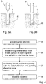
- the above named objects are achieved by establishing, in a first method step, an interference fit between the insert portion and the wall, in particular the lateral wall, of the opening in which the insert portion is to be anchored, and only then applying the energy which causes the liquefaction, which is such achieved mainly where the interference fit is active.
- the anchorage achieved with this method is of a similar strength (per anchorage area unit) as the anchorage achieved with the above briefly discussed method according to WO 96/01377 , but it can be carried out without the necessity of moving the bulk of the insert portion over a relevant distance within the opening during the anchoring step, and this independent on the location in which anchorage is desired. This fact relevantly reduces the time necessary for achieving the anchorage.
- the achieved anchorage is very homogeneous.
- a first object comprising a first material and a second object comprising a second material
- the first material is solid (at ambient temperature) and comprises thermoplastic properties (i.e. it is liquefiable with the aid of thermal energy; in the following this material is called "thermoplastic material")
- the second material is also solid (at ambient temperature) and it is penetrable by the first material when the latter is in a liquefied state (i.e. the second material is fibrous or porous, it comprises penetrable surface structures or it cannot resist such penetration under pressure).
- the second material is such that it does not become flowable under the conditions that apply when the first material penetrates the surface structures.
- the second material may be of a material that does not have thermoplastic properties, i.e. a material different from a thermoplastic material.
- the second material may be such that it does not undergo a reversible liquefaction process, which means that it is of a material incapable of undergoing a reversible liquefaction process or of a material that has a melting temperature substantially above a temperature at which the first material becomes flowable.
- its melting temperature or glass transition temperature may be higher than a glass transition temperature or melting temperature of the first material by at least 50°C or at least 80°C or at least 100°C.
- second materials are wood-based materials such as chipboard
- chipboard in this text includes any composite materials manufactured by mixing wood particles of any shape with adhesives, independent of the product's shape, including for example oriented strand board), High Density Fibre board (HDF), Medium Density Fibre board (MDF), or wood, or metallic or ceramic foams or possibly open porous structures of a material based on a not thermoplastic (thermosetting) polymer.
- Either one of the first and second object comprises an opening and the other one comprises an insert portion to be anchored in the opening, wherein the named materials constitute at least part of the surfaces of the insert portion and of the wall of the opening.
- the opening and the insert portion are dimensionally adapted to each other for an interference fit (press-fit), i.e. the insert portion is oversized at least locally compared with the opening, resulting in at least local pressure between insert portion and opening wall when the insert has a desired position within the opening, i.e. resulting in elastic compression of the insert portion and/or the wall of the opening.
- the named first and second materials are arranged opposing each other at least in parts of areas of such compression.
- the second object may comprise the opening and the first object may comprise the insert portion.
- the insert portion is positioned in the desired position within the opening where it is retained by the above named interference fit.
- an interference force is necessary, either for forcing the insert portion into the undersized opening or for pressing wall sections of the opening against the insert portion.
- the magnitude of the interference force correlates substantially with the strength and area of the interference fit and it is mainly dependent on and limited by the relative dimensions of insert portion and opening and on the compressibility of either one or both of the two materials.
- an anchoring step being carried out after the step of establishing the interference fit, energy is applied to one or the other of the objects, wherein the energy is to act as heat in particular in areas (anchoring areas) in which, due to the interference fit, surface areas of insert portion and opening wall are pressed against each other and comprise one each of the thermoplastic and the penetrable material.
- the heat causes the thermoplastic material to liquefy and the pressure of the interference fit causes interpenetration of the two materials, wherein the interference fit is at least partly relaxed.
- the interference fit is to be overcome, such that, at least in the named areas, the vibration causes friction and therewith friction heat between the insert portion and the wall of the opening.
- mechanical vibration e.g. ultrasonic vibration
- the interference fit it is necessary to apply a shearing load between the insert portion and the opening wall, wherein this shearing load may be caused by strong enough vibration of the one of insert portion or opening wall relative to the other one, or by the vibration and an additional shearing force acting between the two objects.
- this shearing load may be caused by strong enough vibration of the one of insert portion or opening wall relative to the other one, or by the vibration and an additional shearing force acting between the two objects.
- this shearing load may be caused by strong enough vibration of the one of insert portion or opening wall relative to the other one, or by the vibration and an additional shearing force acting between the two objects.
- this shearing load may be caused by strong enough vibration of the one of insert portion or opening wall relative to the other one, or by the vibration and an additional shearing force
- thermoplastic material liquefied and dislocated in the anchoring step is re-solidified, whereby in the interpenetration area a sort of composite material is formed, which connects the two objects in a positive fit connection.
- the energy necessary for liquefying the thermoplastic material in the anchoring step is supplied, as above discussed, to either one of the two objects preferably in the form of mechanical vibration, in particular ultrasonic vibration, to be transformed into friction heat at the interface between the insert portion and the wall of the opening.
- the vibration preferably has a main vibration direction parallel to the surfaces of insert portion and opening wall where the interference fit is active. Preferred therefore are, for achieving lateral anchorage, longitudinal vibrations substantially parallel to the depth of the opening or rotary vibrations with an axis substantially parallel to the depth of the opening.
- additional shearing force, if applied is preferably directed parallel to the main vibration direction, i.e. for the above named two cases it acts parallel to the depth of the opening or as torque with an axis parallel to the depth of the opening.
- thermoplastic material and the penetrable material taking part in the anchorage may be present only on selected surfaces of the insert portion and on walls of the opening. However they may also constitute larger portions of the two objects which may comprise further portions of different materials or may fully consist of either the thermoplastic material or the penetrable material.
- one of the two surfaces being pressed together may comprise structures functioning as energy directors, i.e. point-shaped or line-shaped elements protruding from a principal surface. These energy directing structures may or may not disrupt the opposite surface when the interference fit is established and need to be correspondingly taken into account when calculating the oversize of the insertion portion.
- the penetrable material and the thermoplastic material need to have mechanical properties (under the conditions of the step for establishing the interference fit, i.e. usually at ambient temperatures) to be capable to stand the pressure of the interference fit. Creeping of either one of the two materials which impairs the interference fit is preferably to be prevented.
- a penetrable material suitable for the method according to the invention is solid at least under the conditions of the method according to the invention (step of establishing the interference fit and anchoring step), wherein "solid" in the context of the present disclosure is to mean that this material is rigid, substantially not elastically flexible (no elastomer characteristics) and not plastically deformable and it is not or only very little elastically compressible. It further comprises (actual or potential) spaces into which the liquefied material can flow or be pressed for the anchoring. It is e.g. fibrous or porous or comprises penetrable surface structures which are e.g. manufactured by suitable machining or by coating (actual spaces for penetration).
- the penetrable material is capable of developing such spaces under the hydrostatic pressure of the liquefied thermoplastic material, which means that it may not be penetrable or only to a very small degree when under ambient conditions.
- This property implies e.g. inhomogeneity in terms of mechanical resistance.
- An example of a material that has this property is a porous material whose pores are filled with a material which can be forced out of the pores, a composite of a soft material and a hard material or a heterogeneous material (such as wood) in which the interfacial adhesion between the constituents is smaller than the force exerted by the penetrating liquefied material.
- the penetrable material comprises an inhomogeneity in terms of structure ("empty" spaces such as pores, cavities etc.) or in terms of material composition (displaceable material or separable materials).
- the penetrable material needs to have mechanical properties which are predictable and homogeneous enough for giving the interference fit a predicable strength. As this is hardly the case for living bone the method is not suitable for medical purposes.
- an opening for example a blind opening
- the anvil object is subject to a considerable mechanical load due to the interference force.
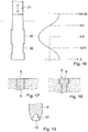
- the anvil object may comprise a board shaped portion (for example by being board shaped or by comprising a board shaped constituent), with broad surfaces and a narrow side face between the broad surfaces, with the opening extending from the narrow side face inwards (i.e., the opening has a mouth on the narrow side surface).
- a board shaped portion for example by being board shaped or by comprising a board shaped constituent
- the opening extending from the narrow side face inwards (i.e., the opening has a mouth on the narrow side surface).
- measures may be taken for preventing cracks or other damages (bulging, or portions flaking off for example) from arising.
- measures for reducing the opposite surface areas that are subject to the interference force may be taken:
- penetrable materials applicable in the method according to the invention are solid materials such as wood, plywood, chipboard, cardboard, concrete brick material, porous glass, foams of metal, ceramic, or polymer materials, or sintered ceramic, glass or metal materials, wherein such materials comprise spaces into which the thermoplastic material can penetrate which spaces are originally filled with air or with another displaceable or compressible material.
- solid materials such as wood, plywood, chipboard, cardboard, concrete brick material, porous glass, foams of metal, ceramic, or polymer materials, or sintered ceramic, glass or metal materials, wherein such materials comprise spaces into which the thermoplastic material can penetrate which spaces are originally filled with air or with another displaceable or compressible material.
- composite materials which have the above stated properties or materials with surfaces comprising a suitable roughness, suitable machined surface structures or suitable surface coatings (e.g. consisting of particles). If the penetrable material has thermoplastic properties it is necessary that it maintains its mechanical strength during the anchoring step either by further comprising a mechanically stable phase or by having a considerably higher melting temperature
- thermoplastic material suitable for the method according to the invention is, under the conditions of the step of establishing the interference fit, also solid in the sense as above described for the penetrable material. It preferably comprises a polymeric phase (especially C, P, S or Si chain based) that transforms from solid into liquid or flowable above a critical temperature range, for example by melting, and re-transforms into a solid material when again cooled below the critical temperature range, for example by crystallization, whereby the viscosity of the solid phase is several orders of magnitude (at least three orders of magnitude) higher than of the liquid phase.
- a polymeric phase especially C, P, S or Si chain based
- the thermoplastic material will generally comprise a polymeric component that is not cross-linked covalently or cross-linked in a manner that the cross-linking bonds open reversibly upon heating to or above a melting temperature range.
- the polymer material may further comprise a filler, e.g. fibres or particles of material which has no thermoplastic properties or has thermoplastic properties including a melting temperature range which is considerably higher than the melting temperature range of the basic polymer.
- thermoplastic material applicable in the method according to the invention are thermoplastic polymers, co-polymers or filled polymers, wherein the basic polymer or co-polymer is e.g. polyethylene, polypropylene, polyamides (in particular Polyamide 12, Polyamide 11, Polyamide 6, or Polyamide 66), Polyoxymethylene, polycarbonateurethane, polycarbonates or polyester carbonates, acrylonitrile butadiene styrene (ABS), Acrylester-Styrol-Acrylnitril (ASA), Styreneacrylonitrile, polyvinyl chloride, polystyrene, or Polyetherketone (PEEK), Polyetherimide (PEI), Polysulfon (PSU), Poly(p-phenylene sulfide) (PPS), Liquid crystall polymers (LCP) etc.
- LCPs are of particular interest since their sharp drop in viscosity during melting enables them to penetrate in very fine spaces in the penetrable material.
- either one of the two objects to be joined needs to be able to transfer the vibration energy, preferably with a minimum of energy loss, from a proximal object side, where a vibrating tool is applied, to a distal side, where the insert portion or the opening is arranged. If this object is fully made of the thermoplastic material the latter will need an elasticity coefficient (at ambient temperature) of at least 0.5.GPa or preferably of at least 1.0 GPa.
- thermoplastic material and the penetrable material need to be adapted to each other such that a suitable interference fit and the desired penetration are possible and result in a suitable anchorage.
- a material pairing which has proved to be advantageous is e.g. the pairing of plywood (penetrable material) and polyamid (thermoplastic material).
- Mechanical vibration or oscillation suitable for the method according to the invention has preferably a frequency between 2 and 200 kHz (even more preferably between 10 and 100 kHz, or between 20 and 40 kHz) and a vibration energy of 0.2 to 20 W per square millimeter of active surface.
- the vibrating tool e.g. sonotrode
- the vibrating tool is e.g. designed such that its contact face oscillates predominantly in the direction of the tool axis (longitudinal vibration) and with an amplitude of between 1 and 100 ⁇ m, preferably around 30 to 60 ⁇ m.
- Such preferred vibrations are e.g. produced by ultrasonic devices as e.g. known from ultrasonic welding.
- one of the two objects is fixed in a stable position and the vibrating tool is applied to the other object (free object) and, if applicable, the vibrating tool is not only used for transmitting the vibration to the free object but also a shearing force being directed parallel to the depth of the opening.
- the vibrating tool may not be connected to the free object or only loosely, i.e. it acts substantially as a hammer on the latter. Alternatively it may be fixed to the free object such that the vibration is fully transferred to the free object.
- Undesired movement of the two objects relative to each other (or of the insert portion within the opening respectively) due to the shearing force directed parallel to the depth of the opening are limited or prevented by e.g. designing the opening as a blind opening or comprising a relevant cross section reduction, or by arranging an auxiliary anvil within or at the mouth of a through opening and by positioning the insert portion within the opening, in the step of achieving the interference fit, such that its distal end abuts the bottom of the blind opening, or the cross section reduction, or the auxiliary anvil or has a predetermined small distance from the latter.
- the anvil object comprises the opening (e.g. a blind bore, i.e. an opening with a constant circular cross section and a bottom) and it comprises the penetrable material (e.g. it consists of wood or chipboard).
- the free object comprises the insert portion (which is e.g. pin-shaped) and it consists of the thermoplastic material (e.g. polyamide, PA 6.6).
- Anchorage is to be achieved mainly on lateral sides of the insert portion, but preferably also at the bottom of the bore.
- the insert portion has a cross section that is oversized relative to the opening by having a diameter being larger than the diameter of the bore.
- the insert portion is forced into the bore until its distal end substantially contacts the bore bottom with the aid of the interference force which is applied to the proximal end of the pin using any suitable tool, possibly the vibrating tool in a passive state (not vibrating).
- the vibrating tool is activated and, if applicable, is simultaneously pressed against the proximal end of the free object with the additional shearing force.
- axial movement of the bulk of the insert portion may be restricted to compensation of compression of the bottom of the opening and penetration of the penetrable material in the area of this bottom.
- the proximal end of the insert portion may move further due to shortening of the insert portion for compensating laterally displaced liquefied material.
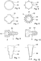
- the for example cylindrical insert portion may comprise energy directing features in form of axially extending ridges which may or may not groove the lateral walls of the opening on establishing the interference fit. If the oversize of the pin cross section is smaller than the radial height of the ridges, the interference fit and therefore the anchorage will be restricted to the areas of the ridges and not concern the valleys between the ridges. Alternatively or in addition it is possible to equip the lateral walls of the opening with energy directing structures.
- the insert portion is preferably fully made of the thermoplastic material but alternatively may comprise a core which extends substantially along a central longitudinal axis of the insert portion and is made of a material (e.g. a metal or a ceramic material or a thermoplastic material with a considerably higher melting temperature than the thermoplastic material to be liquefied) preferably having a higher mechanical strength than the thermoplastic material.
- Exemplary parameters for the above described preferred embodiment of the method according to the invention, in which for the anchoring step vibration as above described is used, are: (a) oversize of insert portion on lateral sides relative to lateral walls of opening: in the region of tenths of millimeters (e.g. 0.1 to 0.5 mm), (b) interference fit: in the region of tenths of N per mm 2 (e.g. 0.1 to 1 N/mm 2 ).
- the anchoring step can be reduced to about half of the time needed if, according to the known method, the insert portion is forced into the opening simultaneously with the application of the vibration.
- This reduction in time constitutes a relevant saving of vibratory energy and a relevant advantage regarding an automated process. Further more, it puts less strain on a proximal face, on which the vibrating tool is hammering, and it reduces the risk of liquefied material being pressed out of the mouth of the opening.
- the invention also concerns a machine for carrying out the method in an automated manner.
- a machine comprises in insertion means for inserting the insert portion in the opening to establish the interference fit, and an anchoring means for carrying out the anchoring process.
- the insertion means may be combined with the anchoring means (for example by a vibrating tool firstly pushing the insert portion into the opening and then being subject to mechanical vibrations to couple energy into the arrangement for the anchoring process) or may be separate therefrom.
- the invention further concerns a set of a machine and a stock of first objects. If the machine further comprises an opening manufacturing means (such as a drill), the opening manufacturing means and the first objects are adapted to each other so that the interference fit can be established by insertion of the insert portion in the opening.
- an opening manufacturing means such as a drill
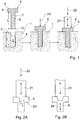
- Fig. 1 illustrates the above already briefly described preferred embodiment of the method according to the invention, wherein the two objects, or the insert portion and the opening respectively, are shown in section parallel to a depth of the opening (longitudinal section). On the left hand side of Fig. 1 the two objects to be joined are illustrated.
- the anvil object 1 comprises the blind opening 2 having a depth D, a lateral wall 3, being substantially parallel to or forming an only small angle with the depth D, and a bottom 4, being e.g. substantially perpendicular to the depth D.
- the anvil object 1 further comprises the penetrable material which is arranged to constitute at least part of the lateral wall 3, e.g. the total of the lateral wall and in addition the bottom wall. Therein the anvil object 1 may be made fully of the penetrable material or may further comprise portions of other materials.
- the free object 5 comprises a distally arranged insert portion 6 and it further comprises the thermoplastic material which constitutes at least part of the lateral surface 7 of the insert portion 6. Therein the free object 5 may be fully made of the thermoplastic material, as illustrated or only partly.
- Insert portion 6 and opening 2 are adapted to each other in the above described manner (interfering cross sections, axial length of insert portion sufficient for enabling abutment of its distal end 10 on bottom 4).
- the free object 5 may further comprise a proximal portion 8 (e.g. shaped like a head), wherein a proximal face 9 thereof is equipped for applying tools used during the step of establishing the interference fit and during the anchoring step.
- the two objects 1 and 5 are shown after establishment of the interference fit.
- the interference force 20 is applied to the proximal face 9 of the free object 5 using any suitable tool (not illustrated).
- the interference fit can be established by providing the anvil object 1 e.g. in a plurality of sections which all comprise parts of the opening and by closing the sections around the insert portion 6, wherein the force by which the sections are moved against each other constitutes the interference force (see Fig. 20 ).
- Fig. 1 On the right hand side of Fig. 1 the two objects 1 and 5 are shown when joined, i.e. after the anchoring step.
- the free element 5 is anchored in the opening 2 in the area of its lateral surfaces 7 (or in the region of the lateral wall 3 of the opening 2 respectively) and in the region of the distal end 10 of the insert portion (or the bottom 4 of the opening 2 respectively).
- the anchoring step is carried out with the help of a vibrating tool 21, which is pressed against the proximal face 9 of the free object 5.
- the length L of the insert portion 6 being originally greater than the depth D of the opening 2 allows movement of the free object 5 or its proximal portion 8 respectively against the anvil object 1 for compensating for the liquefied material which is displaced during the anchoring step.
- the anchoring step is to be terminated, unless further anchoring is desired between the distal face of the proximal portion 8 and the surface of the anvil object 1. Termination of the anchoring step can alternatively or in addition be determined by a predetermined time interval for the anchoring step or by a predetermined maximum value of the shearing force 22.
- Figs. 2A and 2B illustrate two alternatives for carrying out the anchoring step, which alternatives regard the interface between the vibrating tool and the proximal face of the free object as briefly mentioned already further above.
- the vibrating tool 21 is only pressed against (not connected to) the proximal face of the free object 5 with the aid of the shearing force 22, wherein it is preferable to design the vibrating tool for maximal longitudinal vibration at its distal face.
- the shearing force does not only help to overcome the interference fit for enabling the friction but it also serves the bottom anchorage as known from e.g. WO 98/042988 .
- the vibrating tool 21 is rigidly connected to the free object 5, the connection being able to transmit the total vibration (double arrow 24) to the free object 5.
- the vibratory energy is large enough for overcoming the interference fit, and if the anvil object is sufficiently stably fixed or has a sufficient inertia, no additional shearing force is necessary for achieving lateral anchorage.
- Such method is in particular applicable when the opening is not a blind opening but a through tunnel. If the opening still comprises a bottom and anchorage in this bottom in addition to the lateral anchorage is desired, a sufficient "shearing" force for such bottom anchorage is needed, which in addition may supplement the vibration for overcoming the interference fit.
- Figs. 3A and 3B illustrate two alternatives for achieving stronger bottom anchorage, wherein only the distal end of the insert portion 6 of the free object 5 and the opening 2 of the anvil object 1 are shown.
- a tapering distal end 10 of the insert portion 6 is paired with a substantially flat bottom surface 4 of the opening 2.
- a substantially blunt distal end 10 of the insert portion 6 is paired with an opening bottom 4 comprising a cone or similar shape having at least one elevation. While the alternative according to Fig. 3A favors interpenetration parallel to the depth of the opening, the alternative according to Fig. 3B favors lateral diversion of the liquefied material.
- Fig. 4 is a flow diagram of the method according to the invention. This diagram shows that the method comprises the following steps: step 25 of providing the two objects, step 26 of establishing the interference fit between the insert portion and the opening with the aid of the interference force, step 27 of anchoring the insert portion in the opening with the aid of mechanical vibratory energy and possibly the additional shearing force, and finally step 28 of stopping the vibration and of re-solidification of the material liquefied in the anchoring step.
- the time sequence of steps 25 to 28 is the illustrated one and cannot be altered.
- step 25 and 26 there may be pauses between step 25 and 26 and/or between steps 26 and 27, wherein, as mentioned further above, a pause between step 25 and 26 has to be carefully planned if either one of the thermoplastic and the penetrable material have creeping tendencies.
- Figs. 5 to 8 illustrate exemplary pairs of cross sections of insert portion and opening adapted to each other to be suitable at least for the preferred embodiment of the method according to the invention as illustrated in Fig. 1 .
- the cross section 30 of the insert portion is shown with a continuous line and is projected over the cross section 31 of the opening which is shown with a broken line.
- the drawn cross sections 30 and 31 are the cross sections of the provided elements (before the steps of establishing the interference fit and before the anchoring step).
- the oversize of the insert portion is not drawn in scale (too large).
- the cross sections 30 and 31 will extend over most of the axial insert length and opening depth.
- the cross sections may change in form and/or size along the axial insert length and/or opening depth.
- Fig. 5 shows two circular cross sections 30 and 31 with the required oversize of the cross section 30 of the insert portion.
- Such a cross section pairing will result in a uniform anchorage on the whole circumference of insert portion and opening provided that the penetrable material of the lateral opening wall is uniform in the areas of the interference fit.
- Fig. 6 shows a circular cross section 31 for the opening and a cross section 30 for the insert portion with a plurality of ribs 32.
- the ribs 32 serve as energy directing structures. If sufficiently sharp, the ribs 32 may penetrate the lateral wall of the opening on establishing the interference fit which has to be taken into consideration when determining the interference of the cross sections. If only the ribs are oversized but not the valleys therebetween, anchorage will only occur in the vicinity of these ribs. Similar effects can be achieved by equipping the cross section 31 of the opening with points protruding from the opening wall while still keeping the cross section 30 of the insert portion substantially circular.
- Fig. 7 shows a pairing of a circular cross section 31 for the opening and a cross section 30 for the insert portion which has indentations 33 of a sufficient depth, such that in their area no interference fit will be established and therewith no anchorage will occur. Also in this case the indentations may be provided in the wall of the opening instead of in the insert portion.
- the insert portion in at least one depth has a star shaped cross section.
- the star-shaped cross section includes sharp edges 32 that like in the embodiments of Figs. 6 and 7 may serve as energy directors.
- the depth of the indentations 33 between the edges is such that even if the edges cut into the penetrable material, there remains some space into which in the anchoring step some thermoplastic material may flow. This may especially be advantageous in case the penetrable material has a comparably low porosity.
- anchorage may occur along the full periphery of the insert portion.
- Fig. 9 depicts a free object 5 with a core 82 of a for example metallic material embedded in a thermoplastic coating 71.
- thermoplastic material does not need to constitute the entire surface. Rather, it is sufficient if at least part of the surface area, loaded by the interference fit is constituted by the thermoplastic material.
- Fig. 10 shows an example where the thermoplastic material 81 is only present at the distal end. Alternatives with for example axially extending strips of the thermoplastic material are possible, too.
- Figs. 11 to 16 show pairings of insert portions and openings suitable for the method according to the invention, wherein the insert portions and openings are sectioned along the insert portion length or the opening depth respectively, and wherein again the section 35 of the insert portion is shown with a continuous line and is projected over the section 36 of the opening which is drawn as broken line.
- the sections 35 and 36 are the sections of the elements as provided (i.e. before the step of achieving the interference fit and before the anchoring step).
- Fig. 11 shows a pairing of a tapering insert portion with a tapering opening, wherein the tapering is consists of a plurality of steps 37, wherein the steps on insert portion and opening have substantially the same axial lengths, and wherein the cross sections of insert portion and opening between steps are adapted to each other in substantially the same manner (similar oversize).
- Fig. 12 shows a pairing of a tapering insert portion with a tapering opening, wherein the tapering in both cases is continuous and has an angle A relative to the insert portion length and the opening depth of not more than 10 to 15°.
- the cross sections of insert portion and opening over insert portion length and opening depth have preferably all similar forms but decreasing sizes.
- Fig. 13 illustrates the already further above discussed embodiment using an auxiliary anvil 40 positioned in a through opening and serving for counteracting the shearing force and possibly also the interference force. If the auxiliary anvil 40 is to be removed from the opening, care is to be taken when designing the anvil surface and the distal end of the insert portion that no connection between the two is effected in the anchoring step.
- the auxiliary anvil may have a face directed towards the insert portion comprising an elevation, which may function as energy directing element for liquefaction at the distal end of the insert portion.
- Fig. 14 illustrates the already further above discussed embodiment in which movement of the insert portion in the opening is limited by a step 41 in the opening where the cross section of the opening is reduced in such a manner that the distal end of the insert portion cannot be moved past the step neither under the influence of the interference force nor under the influence of the shearing force.
- Fig. 15 illustrates a further exemplified embodiment of the method according to the invention wherein the object 5 comprising the insert portion and the thermoplastic material constitutes a sort of blind rivet.
- a distal portion 5.1. of the object 5 is to be anchored in an opening of a first object 1.1 comprising the penetrable material and a proximal portion 5.2 of the object 5 is to be anchored in an opening of a second object 1.2 comprising the penetrable material.
- the interference force, the vibration and, if applicable, the shearing force are preferably applied to object 1.2 (free object) and object 1.1 is kept stable (anvil object) wherein object 5 functions as both free and anvil object.
- Fig. 16 illustrates a pairing of longitudinal sections 35 and 36 of insert portion and opening in which interference fit and anchorage are limited to predefined areas alternating with areas of no interference fit and anchorage along the longitudinal axis of the insertion portion or the opening depth respectively. This is achieved by cross sections of alternating sizes. The same effect can be achieved by pairing a cylindrical insert portion with an opening comprising portions of differing cross section sizes or vice versa. If the vibrating tool 21 is designed and energized for longitudinal vibration it is advantageous to arrange the above named areas of interference fit and anchorage at locations with large amplitude and the above named areas with no interference fit and no anchorage at locations with small amplitude.
- Figs. 17 and 18 show further exemplary embodiments of proximal ends of insert portions anchored in openings, which are achievable with the method according to the invention and in particular with the preferred embodiment thereof as illustrated in Fig. 1 .
- Both Figs. 17 and 18 are partial sections parallel to the axial length of the insert portion or the opening respectively, wherein only a mouth region of the opening and a proximal portion of object 5 are shown.
- Fig. 17 shows an object 5 with an insert portion only (no proximal portion) which is anchored in the opening with its proximal face 9 flush with the surface of the object 1 or in the mouth of the opening respectively.
- This is achieved by dimensioning the object 5 with a length greater than the opening depth wherein the difference substantially corresponds with the expected shortening of object 5 during the anchoring step due to thermoplastic material penetrating the lateral and bottom wall of the opening.
- insert portion length and opening depth it is possible to achieve any desired position of the proximal face 9 relative to the mouth of the opening.
- Fig. 18 shows a headed object 5, e.g. similar to the one shown in Fig. 1 , wherein the head-shaped proximal portion 8 is countersunk in a corresponding enlargement of the opening cross section adjacent to the mouth of the opening.
- Fig. 19 illustrates an embodiment of an insert portion 6 with a hollow distal end.
- the distal end of the insert portion 6 is provided with a hollow space 61 so that the distal end 10 is somewhat flexible and provides less resistance to deformations when the insert portion is subject to a radial compression force, compared to an embodiment with a blunt distal end. Due to this, during introduction into the opening the interference force rises gradually instead of being particularly strong initially.
- Fig. 20 illustrates an embodiment of the method according to the invention in which, as mentioned already further above, the interference fit is established not by forcing the insert portion into the opening but by positioning the insert portion between wall parts of an opening and clamping the wall parts against the insert portion.
- the wall parts are constituted by narrow surfaces of boards (anvil objects 1.3 and 1.4), e.g. chipboards, which extend substantially parallel and which constitute between them the opening 2.
- the insert portion 6 has the form of a lath.
- the insert portion is positioned and clamped between the wall parts wherein the anvil objects 1.3 and 1.4 are pressed against the free object 5 (interference force 20).
- Fig. 20 shows above the objects before the step of establishing the interference fit and below after the anchoring step.
- the free object 5 has a plurality of wings 62 attached to the insert portion 6.
- the wings 62 may be comparably soft and thereby assist the location of the insert portion 6 in the correct position in the opening 2 without causing cracking in the anvil object 1.
- the cross section of the insert portion body i.e. that part of the insert portion that is not constituted by the wings 62
- the cross section of the insert portion body may approximately correspond to the cross section of the opening 2 or be even slightly lower than the latter so that the interference force is only present at the location of the wings 62.
- This embodiment may be suited for especially weak or brittle penetrable material.
- the wings 62 may be dimensionally stable and serve as cutting blades. Also in this variant, the wings 62 may stabilize the insert portion during insertion. Embodiments with the wings 62 are examples of embodiments that are particularly suited for processes in which the insert portion 6 is shot into the opening, for example comparable to an air gun like process.
- Fig. 22 shows, further to Fig. 16 , an example of an embodiment with a cross section pairing of insert portion and opening differing along the depth of the opening such that the interference fit is restricted to predetermined areas arranged along this depth.
- the interference fit is restricted to deeper sections thus minimizing the risk of cracks or other damages at the rim of the opening where the second object 1 is weakest, especially if it is board shaped and the opening extends from the narrow face.
- the opening is stepped, whereas the insert portion is essentially cylindrical (with the possible exception of energy directors and/or a slight taper).
- An opening having an inner (distal), smaller diameter section 2.1 and an outer (proximal) larger diameter section 2.2 may for example be manufactured by a dual drilling process, with two different drills. Also drills with a step feature are possible.
- the cross section (diameter d 1 in the depicted embodiment assuming an approximately circular cross section) of the inner section 2.1 will be smaller than the cross section (diameter d i ) of the insert portion to generate the interference fit, whereas the cross section (diameter d 2 ) of the outer section 2.2 may approximately correspond to the diameter of the insert portion or may even be slightly larger.
- Fig. 23 illustrates a variant of the embodiment of Fig. 22 with multiple steps.
- the diameters of the respective sections are such that no interference fit is present in the depicted configuration where the insert portion is only partially inserted, and an interference fit will arise if the distal-most section 6.2 of the insert portion is pressed into the innermost portion 2.1 of the opening and the more proximal section 6.1 enters the middle section 2.2 of the opening but not within the proximal-most section 2.3 of the opening.
- Fig. 24 shows a further embodiment.
- the anvil object 1 is assumed to be a board having two broad surfaces 81, 82 a narrow side face 83, with the opening 2 in the narrow side face.
- the embodiment of Fig. 24 is an example of an embodiment in which the interference force is caused from an inside of the free object 5, starting for example only immediately prior to the anchoring step.
- the free object 5 is provided with an interior opening 70 into which an expansion element 71 is pushed, the expansion element having at least in some axial depths a cross section larger than a cross section of the interior opening.
- the insert portion 6 and the opening 2 may be adapted to each other so that no interference fit or an interference fit with only a small interference force is established when the insert portion 6 is in the opening 5 before the expansion element 71 is placed.
- the expansion element 71 may for example be introduced by a force exerted by the vibrating tool 21 (sonotrode) immediately prior to the step of causing the mechanical vibration to impinge on the free object by the vibrating tool 21.
- a configuration with the anvil object having a board shaped section and with the opening extending from the narrow side face is applicable to all embodiments described in this text.
- Applications include the furniture industry, where a head portion 8 of the free object 5 may serve male part of a joint co-operating a female parts of a second furniture part, for example as described in as WO 2013/104422 by Inter Buy Systems B.V.
- Fig. 25 yet schematically illustrates elements of a machine for carrying out the method described herein in an automated manner.
- the machine comprises, in addition to the vibrating tool 21, a gripping arrangement 91 for positioning the free object 5 relative to the anvil object 1 prior to the step of establishing the interference fit and also, at least in part, during this step.
- the vibrating tool 21, prior to being subject to the vibrations may be used, for example by pressing the insert portion into the opening.
- the machine may comprise a separate insertion station, where the interference fit is established by a corresponding insertion tool, for example a pusher tool.
- the vibrating tool is connected to a vibration source 92, such as a piezoelectric transducer, that causes the vibrating tool to vibrate.
- a vibration source 92 such as a piezoelectric transducer
- the machine may optionally further comprise an opening producing device, such as a drilling device 93, comprising a drill 94 the diameter of which is adapted to an outer diameter of the insert portion 6 in a manner that when the insert portion is inserted in the opening the interference fit is established, i.e. the drill 94 is configured to form an opening with a diameter somewhat less than an outer diameter of the insert portion.
- an opening producing device such as a drilling device 93, comprising a drill 94 the diameter of which is adapted to an outer diameter of the insert portion 6 in a manner that when the insert portion is inserted in the opening the interference fit is established, i.e. the drill 94 is configured to form an opening with a diameter somewhat less than an outer diameter of the insert portion.
- the machine may be an automated machine for mass production, comprising several stations and transport means for conveying the anvil object from station to station.
- the machine may comprise an opening forming (drillings) station, an insertion station, and an anchoring station, as well as means for conveying anvil objects from station to station in a cycled manner.
- a machine may comprise further stations, such as a cutting-to-size station, arranged before the opening forming station.
- it may comprise storages for unprocessed anvil objects, processed anvil objects (to which the objects are conveyed after the method has been carried out) and/or for free objects.
- An anchoring device of polyamide (PA 6.6 filled with 15% of glass fibers) was joined to a porous structural foam of a density in the range of 0.5 to 0.8 g/cm 3 , using the method as illustrated in Fig. 1 .
- the opening provided in the foam was a blind bore.
- the inserted portion of the device was cylindrical, had a circular cross section (no energy directing structures) with a diameter being 3% oversized to create the interference fit, an overlength of 25% with restpect to the bore depth, and a blunt distal end.
- the device was forced into the opening which necessitated an interference force of about 10 MPa related to the device cross section. In the inserted position the distal end of the device abutted the bottom of the blind bore.
- the foam was locally fixed (anvil object) and ultrasonic vibration was coupled into the proximal face of the device (free object) and simultaneously the pin was pressed against the bottom of the opening with a shearing force of about twice the interference force, using a stationary ultrasonic device by Branson (Series 2000). Therein the device was not attached to the sonotrode of the ultrasonic device.
- the anchoring step was carried out with a vibration frequency of about 20 kHz and a longitudinal amplitude at the distal end of the sonotrode in the range of 50 to 90 ⁇ m. After about 0.3 sec of anchoring time the device was fully seated in the foam and the vibration was stopped.
- the overlength of the device was consumed by displacement of the thermoplastic material into the bottom of the opening, and possibly also by an increase of the depth of the opening due to either the interference force or the shearing force, and further by radial displacement of the thermoplastic material.
- the anchorage on the lateral sides of the device was very uniform all around the device and in particular along its length. For removing the device from the foam a force had to be applied which was about twice the force needed for removal of an identical device anchored with a similar method in a non-undersized bore (no lateral interference fit and therefore hardly any lateral anchorage). This allows the conclusion that the lateral anchorage induced by the lateral interference fit contributes about the same amount of retention strength as the anchorage at the bottom of the bore.
Description
- The invention is in the field of mechanical engineering and construction and concerns a method for joining two objects. One of the objects comprises an insert portion and the other object comprises an opening, and, for the two objects to be joined, the insert portion is anchored in the opening, wherein, in the anchoring area, one of the objects comprises a solid material having thermoplastic properties, and the other object comprises a solid material which is penetrable by the material having thermoplastic properties when liquefied. The penetrable material is e.g. fibrous or porous, it is e.g. a structural foam.
- From e.g. the publications
WO 96/01377 (Createc WO 98/042988 (Woodwelding WO 2006/002569 (Woodwelding ) orWO 2008/080238 it is known to anchor inserts comprising materials having thermoplastic properties in fibrous or porous materials such as e.g. chipboard or wood. For such anchoring, the insert is positioned relative to the opening, and then mechanical vibration, in particular ultrasonic vibration, and a force directed for pressing the insert into the opening are simultaneously applied to the insert. In the step of positioning the insert, no relevant force is used, i.e., on application of the vibratory energy, the positioned insert will vibrate freely, or will, due to the named force pressing it against the fibrous or porous material, transmit the vibratory energy to the latter. In the step of applying vibration and force, the material having thermoplastic properties is liquefied due to friction heat at least where in contact with the fibrous or porous material and it penetrates into the fibrous or porous material of the walls of the opening and forms on re-solidification a positive fit connection with the porous or fibrous material. - According to the publication
WO 96/01377 - According to the publications
WO 98/042988 WO 2006/002569 , the insert and the blind opening in which the insert is to be anchored are adapted to each other such that the insert on being positioned in the opening sits on the bottom of the opening. During the application of the ultrasonic vibration, the insert is pressed against this bottom. This results in liquefaction of the material having thermoplastic properties in particular in the region of the distal insert end, i.e. in a substantially distal anchorage at the bottom of the opening but hardly any lateral anchoring, wherein the bulk of the insert is not or only very little moved during the application of the vibration. -
US 4,784,591 A andFR 2472351 A1 -
US 5,879,115 teaches a method and an apparatus for joining a plastic insert to a plastic base having a recess therein. The process relies on plastic material of both, the insert and the base to melt and to flow into spaces where the plastics of the insert and the base are melded together into a puddle to yield, after re-solidification, an integral joint (a weld). Applications of this approach are restricted to bonds between two objects that are both of thermoplastic material, the thermoplastic materials being capable of intermixing integrally with each other. - The object of the present invention is to provide an alternative method for joining two objects, wherein one of the objects comprises an insert portion and the other one comprises an opening, wherein, for the joining, the insert portion is anchored in the opening, and wherein, at least in areas in which such anchoring is desired, one of the objects comprises a solid material having thermoplastic properties, and the other object comprises a solid material which is penetrable by the material having thermoplastic properties when liquefied.
- A further object of the invention is to improve the above briefly described, known methods in which such joining is achieved with the aid of energy provided in the form of mechanical vibration, in particular ultrasonic vibration. Using the method according to the invention it is to be possible to achieve with the simplest design of insert and opening and within a minimum time of vibration application a particularly lateral anchorage of a very high uniformity even if the desired anchoring area is relatively large.
- Generally speaking, the above named objects are achieved by establishing, in a first method step, an interference fit between the insert portion and the wall, in particular the lateral wall, of the opening in which the insert portion is to be anchored, and only then applying the energy which causes the liquefaction, which is such achieved mainly where the interference fit is active. The anchorage achieved with this method is of a similar strength (per anchorage area unit) as the anchorage achieved with the above briefly discussed method according to
WO 96/01377 - According to the invention, a first object comprising a first material and a second object comprising a second material are provided, wherein the first material is solid (at ambient temperature) and comprises thermoplastic properties (i.e. it is liquefiable with the aid of thermal energy; in the following this material is called "thermoplastic material"), and the second material is also solid (at ambient temperature) and it is penetrable by the first material when the latter is in a liquefied state (i.e. the second material is fibrous or porous, it comprises penetrable surface structures or it cannot resist such penetration under pressure). Especially, the second material is such that it does not become flowable under the conditions that apply when the first material penetrates the surface structures. For example, the second material may be of a material that does not have thermoplastic properties, i.e. a material different from a thermoplastic material. The second material may be such that it does not undergo a reversible liquefaction process, which means that it is of a material incapable of undergoing a reversible liquefaction process or of a material that has a melting temperature substantially above a temperature at which the first material becomes flowable. For example, if the second material is meltable, its melting temperature or glass transition temperature may be higher than a glass transition temperature or melting temperature of the first material by at least 50°C or at least 80°C or at least 100°C.
- According examples of second materials are wood-based materials such as chipboard ("chipboard" in this text includes any composite materials manufactured by mixing wood particles of any shape with adhesives, independent of the product's shape, including for example oriented strand board), High Density Fibre board (HDF), Medium Density Fibre board (MDF), or wood, or metallic or ceramic foams or possibly open porous structures of a material based on a not thermoplastic (thermosetting) polymer.
- Either one of the first and second object comprises an opening and the other one comprises an insert portion to be anchored in the opening, wherein the named materials constitute at least part of the surfaces of the insert portion and of the wall of the opening. The opening and the insert portion are dimensionally adapted to each other for an interference fit (press-fit), i.e. the insert portion is oversized at least locally compared with the opening, resulting in at least local pressure between insert portion and opening wall when the insert has a desired position within the opening, i.e. resulting in elastic compression of the insert portion and/or the wall of the opening. Therein the named first and second materials are arranged opposing each other at least in parts of areas of such compression.
- Especially, the second object may comprise the opening and the first object may comprise the insert portion.
- In a method step of establishing the interference fit, the insert portion is positioned in the desired position within the opening where it is retained by the above named interference fit. For achieving the interference fit, i.e. for generating the compression between insert portion and opening wall an interference force is necessary, either for forcing the insert portion into the undersized opening or for pressing wall sections of the opening against the insert portion. The magnitude of the interference force correlates substantially with the strength and area of the interference fit and it is mainly dependent on and limited by the relative dimensions of insert portion and opening and on the compressibility of either one or both of the two materials.
- In an anchoring step being carried out after the step of establishing the interference fit, energy is applied to one or the other of the objects, wherein the energy is to act as heat in particular in areas (anchoring areas) in which, due to the interference fit, surface areas of insert portion and opening wall are pressed against each other and comprise one each of the thermoplastic and the penetrable material. The heat causes the thermoplastic material to liquefy and the pressure of the interference fit causes interpenetration of the two materials, wherein the interference fit is at least partly relaxed.
- If the energy is applied as mechanical vibration (e.g. ultrasonic vibration), the interference fit is to be overcome, such that, at least in the named areas, the vibration causes friction and therewith friction heat between the insert portion and the wall of the opening. For overcoming the interference fit, it is necessary to apply a shearing load between the insert portion and the opening wall, wherein this shearing load may be caused by strong enough vibration of the one of insert portion or opening wall relative to the other one, or by the vibration and an additional shearing force acting between the two objects. For preventing undesired movement, in particular translational movement of the two objects relative to each other due to the shearing force, it may be necessary to counteract the latter in a suitable manner.
- In a further method step the supply of energy is stopped until the thermoplastic material liquefied and dislocated in the anchoring step is re-solidified, whereby in the interpenetration area a sort of composite material is formed, which connects the two objects in a positive fit connection.
- The energy necessary for liquefying the thermoplastic material in the anchoring step is supplied, as above discussed, to either one of the two objects preferably in the form of mechanical vibration, in particular ultrasonic vibration, to be transformed into friction heat at the interface between the insert portion and the wall of the opening. The vibration preferably has a main vibration direction parallel to the surfaces of insert portion and opening wall where the interference fit is active. Preferred therefore are, for achieving lateral anchorage, longitudinal vibrations substantially parallel to the depth of the opening or rotary vibrations with an axis substantially parallel to the depth of the opening. The above named additional shearing force, if applied, is preferably directed parallel to the main vibration direction, i.e. for the above named two cases it acts parallel to the depth of the opening or as torque with an axis parallel to the depth of the opening.
- Other sorts of energy such as e.g. irradiation with electromagnetic energy for which suitable absorbing means are to be provided at the locations where the interference fit is active, or corresponding heating (e.g. inductive or resistive heating) are applicable also.
- As mentioned above, the thermoplastic material and the penetrable material taking part in the anchorage may be present only on selected surfaces of the insert portion and on walls of the opening. However they may also constitute larger portions of the two objects which may comprise further portions of different materials or may fully consist of either the thermoplastic material or the penetrable material.
- In areas in which the interference fit acts either one of the two surfaces being pressed together may comprise structures functioning as energy directors, i.e. point-shaped or line-shaped elements protruding from a principal surface. These energy directing structures may or may not disrupt the opposite surface when the interference fit is established and need to be correspondingly taken into account when calculating the oversize of the insertion portion.
- The penetrable material and the thermoplastic material need to have mechanical properties (under the conditions of the step for establishing the interference fit, i.e. usually at ambient temperatures) to be capable to stand the pressure of the interference fit. Creeping of either one of the two materials which impairs the interference fit is preferably to be prevented. This is achieved by selecting materials with substantially no creeping tendency at the temperature of the step of establishing the interference fit (amorphous polymers below their glass transition temperature or preferably at least 50°C below their glass transition temperature and part crystalline polymers below their melting temperature) or by keeping a time interval between the step of establishing the interference fit and the step of anchoring short enough for starting the anchoring step before the interference fit is too much impaired by the creeping (the shorter the named time interval is, the more creeping tendency of either one of the materials can be tolerated, i.e. for polymers: the nearer the used temperature can be to the above given temperature limits). If the energy is applied in form of mechanical vibration, the penetrable material further needs to be capable to stand the vibratory friction of the anchoring step.
- A penetrable material suitable for the method according to the invention is solid at least under the conditions of the method according to the invention (step of establishing the interference fit and anchoring step), wherein "solid" in the context of the present disclosure is to mean that this material is rigid, substantially not elastically flexible (no elastomer characteristics) and not plastically deformable and it is not or only very little elastically compressible. It further comprises (actual or potential) spaces into which the liquefied material can flow or be pressed for the anchoring. It is e.g. fibrous or porous or comprises penetrable surface structures which are e.g. manufactured by suitable machining or by coating (actual spaces for penetration). Alternatively the penetrable material is capable of developing such spaces under the hydrostatic pressure of the liquefied thermoplastic material, which means that it may not be penetrable or only to a very small degree when under ambient conditions. This property (having potential spaces for penetration) implies e.g. inhomogeneity in terms of mechanical resistance. An example of a material that has this property is a porous material whose pores are filled with a material which can be forced out of the pores, a composite of a soft material and a hard material or a heterogeneous material (such as wood) in which the interfacial adhesion between the constituents is smaller than the force exerted by the penetrating liquefied material. Thus, in general, the penetrable material comprises an inhomogeneity in terms of structure ("empty" spaces such as pores, cavities etc.) or in terms of material composition (displaceable material or separable materials).
- For the method according to the invention to produce a suitably repeatable joining quality the penetrable material needs to have mechanical properties which are predictable and homogeneous enough for giving the interference fit a predicable strength. As this is hardly the case for living bone the method is not suitable for medical purposes.
- In embodiments with an opening, for example a blind opening, into which the insert portion is inserted by introducing the insert portion in the opening the anvil object is subject to a considerable mechanical load due to the interference force. Depending to the composition of the penetrable material or possibly other materials of the anvil object, there may be a risk of cracks or other damages being caused by the introduction of the insert portion into the opening prior to the step of anchoring.
- For example, in embodiments, the anvil object may comprise a board shaped portion (for example by being board shaped or by comprising a board shaped constituent), with broad surfaces and a narrow side face between the broad surfaces, with the opening extending from the narrow side face inwards (i.e., the opening has a mouth on the narrow side surface).
- Generally, if necessary, measures may be taken for preventing cracks or other damages (bulging, or portions flaking off for example) from arising. Especially, measures for reducing the opposite surface areas that are subject to the interference force may be taken:
- The cross sections of the insert portion and of the opening are adapted to each other by not having a same shape so that the interference fit is limited to only parts of the circumference of the cross sections.
- ∘ If the distance between parts of subject to the interference force is similar to or smaller than a flow distance of the thermoplastic material during the subsequent anchoring step, then nevertheless the anchoring may concern the full circumference, with portions between the interference force portions serve as additional space where the squeezed thermoplastic material can go to. For example, if the cross section of the opening is round and the cross section of the insert portion is star shaped with closely spaced teeth, then the thermoplastic material during the anchoring may flow to fill spaces between the teeth.
- ∘ If the distance between the interference force portions is large, then anchoring will be accordingly limited to parts of the circumference, essentially corresponding to the interference force portions.
- ∘ In embodiments of this concept, edges of such cross sections may function as energy directing elements and/or may be pressed into the lateral wall of the opening on establishing the interference fit.
- In addition or as an alternative, the cross section pairing of insert portion and opening may differ along the depth of the opening such that the interference fit is restricted to predetermined areas arranged along this depth. Especially, the interference fit may be restricted to areas at a distance from the mouth of the opening (to deeper portions) because the risk of cracks or other damages is the highest at the rim of the opening.
∘ In examples, the opening may be stepped or tapered with a lower diameter at deeper positions, whereas the insert portion does not have any steps/taper or is stepped/tapered differently. - In addition or as yet another alternative, the insert portion may be provided with a hollow part, especially if it is of a for example slightly elastic material. In examples, the distal end may be hollow.
- In addition or as a further alternative, the insert portion may be provided with stiff or flexible/soft wings. The insert portion may then for example be shot into the opening by air pressure or similar. The wings may ensure that the insert portion is located in a correct position without causing a cracking.
- In addition or as an even further alternative, the interference force may be caused only immediately prior to the anchoring step and after the objects have been positioned relative to one another, from an inside of the first object. Especially, the first object may be provided with an interior opening accessible from the proximal side, and an expansion element may be pushed into the opening for example by the vibrating tool by which thereafter the energy is transferred to the first object. The expansion element in this has a larger cross section than the interior opening so that it expands the first object and thereby causes the interference force from inside.
- Examples of penetrable materials applicable in the method according to the invention are solid materials such as wood, plywood, chipboard, cardboard, concrete brick material, porous glass, foams of metal, ceramic, or polymer materials, or sintered ceramic, glass or metal materials, wherein such materials comprise spaces into which the thermoplastic material can penetrate which spaces are originally filled with air or with another displaceable or compressible material. Further examples are composite materials which have the above stated properties or materials with surfaces comprising a suitable roughness, suitable machined surface structures or suitable surface coatings (e.g. consisting of particles). If the penetrable material has thermoplastic properties it is necessary that it maintains its mechanical strength during the anchoring step either by further comprising a mechanically stable phase or by having a considerably higher melting temperature than the thermoplastic material to be liquefied in the anchoring step.
- A thermoplastic material suitable for the method according to the invention is, under the conditions of the step of establishing the interference fit, also solid in the sense as above described for the penetrable material. It preferably comprises a polymeric phase (especially C, P, S or Si chain based) that transforms from solid into liquid or flowable above a critical temperature range, for example by melting, and re-transforms into a solid material when again cooled below the critical temperature range, for example by crystallization, whereby the viscosity of the solid phase is several orders of magnitude (at least three orders of magnitude) higher than of the liquid phase. The thermoplastic material will generally comprise a polymeric component that is not cross-linked covalently or cross-linked in a manner that the cross-linking bonds open reversibly upon heating to or above a melting temperature range. The polymer material may further comprise a filler, e.g. fibres or particles of material which has no thermoplastic properties or has thermoplastic properties including a melting temperature range which is considerably higher than the melting temperature range of the basic polymer.
- Examples for the thermoplastic material applicable in the method according to the invention are thermoplastic polymers, co-polymers or filled polymers, wherein the basic polymer or co-polymer is e.g. polyethylene, polypropylene, polyamides (in particular Polyamide 12, Polyamide 11,
Polyamide 6, or Polyamide 66), Polyoxymethylene, polycarbonateurethane, polycarbonates or polyester carbonates, acrylonitrile butadiene styrene (ABS), Acrylester-Styrol-Acrylnitril (ASA), Styreneacrylonitrile, polyvinyl chloride, polystyrene, or Polyetherketone (PEEK), Polyetherimide (PEI), Polysulfon (PSU), Poly(p-phenylene sulfide) (PPS), Liquid crystall polymers (LCP) etc. LCPs are of particular interest since their sharp drop in viscosity during melting enables them to penetrate in very fine spaces in the penetrable material. - Usually either one of the two objects to be joined needs to be able to transfer the vibration energy, preferably with a minimum of energy loss, from a proximal object side, where a vibrating tool is applied, to a distal side, where the insert portion or the opening is arranged. If this object is fully made of the thermoplastic material the latter will need an elasticity coefficient (at ambient temperature) of at least 0.5.GPa or preferably of at least 1.0 GPa.
- The thermoplastic material and the penetrable material need to be adapted to each other such that a suitable interference fit and the desired penetration are possible and result in a suitable anchorage. A material pairing which has proved to be advantageous is e.g. the pairing of plywood (penetrable material) and polyamid (thermoplastic material).
- Mechanical vibration or oscillation suitable for the method according to the invention has preferably a frequency between 2 and 200 kHz (even more preferably between 10 and 100 kHz, or between 20 and 40 kHz) and a vibration energy of 0.2 to 20 W per square millimeter of active surface. The vibrating tool (e.g. sonotrode) is e.g. designed such that its contact face oscillates predominantly in the direction of the tool axis (longitudinal vibration) and with an amplitude of between 1 and 100µm, preferably around 30 to 60 µm. Such preferred vibrations are e.g. produced by ultrasonic devices as e.g. known from ultrasonic welding.
- In a preferred embodiment of the anchoring step of the method according to the invention one of the two objects (anvil object) is fixed in a stable position and the vibrating tool is applied to the other object (free object) and, if applicable, the vibrating tool is not only used for transmitting the vibration to the free object but also a shearing force being directed parallel to the depth of the opening. Therein the vibrating tool may not be connected to the free object or only loosely, i.e. it acts substantially as a hammer on the latter. Alternatively it may be fixed to the free object such that the vibration is fully transferred to the free object.
- Undesired movement of the two objects relative to each other (or of the insert portion within the opening respectively) due to the shearing force directed parallel to the depth of the opening are limited or prevented by e.g. designing the opening as a blind opening or comprising a relevant cross section reduction, or by arranging an auxiliary anvil within or at the mouth of a through opening and by positioning the insert portion within the opening, in the step of achieving the interference fit, such that its distal end abuts the bottom of the blind opening, or the cross section reduction, or the auxiliary anvil or has a predetermined small distance from the latter.
- In an exemplary preferred embodiment of the method according to the invention, the anvil object comprises the opening (e.g. a blind bore, i.e. an opening with a constant circular cross section and a bottom) and it comprises the penetrable material (e.g. it consists of wood or chipboard). The free object comprises the insert portion (which is e.g. pin-shaped) and it consists of the thermoplastic material (e.g. polyamide, PA 6.6). Anchorage is to be achieved mainly on lateral sides of the insert portion, but preferably also at the bottom of the bore. The insert portion has a cross section that is oversized relative to the opening by having a diameter being larger than the diameter of the bore. In the step of establishing the interference fit, the insert portion is forced into the bore until its distal end substantially contacts the bore bottom with the aid of the interference force which is applied to the proximal end of the pin using any suitable tool, possibly the vibrating tool in a passive state (not vibrating). In the anchoring step the vibrating tool is activated and, if applicable, is simultaneously pressed against the proximal end of the free object with the additional shearing force.
- In embodiments of this kind, axial movement of the bulk of the insert portion may be restricted to compensation of compression of the bottom of the opening and penetration of the penetrable material in the area of this bottom. The proximal end of the insert portion may move further due to shortening of the insert portion for compensating laterally displaced liquefied material.
- The for example cylindrical insert portion may comprise energy directing features in form of axially extending ridges which may or may not groove the lateral walls of the opening on establishing the interference fit. If the oversize of the pin cross section is smaller than the radial height of the ridges, the interference fit and therefore the anchorage will be restricted to the areas of the ridges and not concern the valleys between the ridges. Alternatively or in addition it is possible to equip the lateral walls of the opening with energy directing structures. The insert portion is preferably fully made of the thermoplastic material but alternatively may comprise a core which extends substantially along a central longitudinal axis of the insert portion and is made of a material (e.g. a metal or a ceramic material or a thermoplastic material with a considerably higher melting temperature than the thermoplastic material to be liquefied) preferably having a higher mechanical strength than the thermoplastic material.
- Exemplary parameters for the above described preferred embodiment of the method according to the invention, in which for the anchoring step vibration as above described is used, are: (a) oversize of insert portion on lateral sides relative to lateral walls of opening: in the region of tenths of millimeters (e.g. 0.1 to 0.5 mm), (b) interference fit: in the region of tenths of N per mm2 (e.g. 0.1 to 1 N/mm2).
- Experiments show that using the above briefly described preferred embodiment of the method according to the invention the anchoring step can be reduced to about half of the time needed if, according to the known method, the insert portion is forced into the opening simultaneously with the application of the vibration. This reduction in time constitutes a relevant saving of vibratory energy and a relevant advantage regarding an automated process. Further more, it puts less strain on a proximal face, on which the vibrating tool is hammering, and it reduces the risk of liquefied material being pressed out of the mouth of the opening. This increases the overall quality of the result of the method in that, even if the named proximal face is made of the thermoplastic material, it is not deformed or undesirably marked during the anchoring step and the region of the mouth of the opening is kept clean. Exemplary alternatives to the above named preferred embodiment of the method according to the invention (as far as not already described further above) are e.g.
- Insert portion and opening are not cylindrical but e.g. tapering either continuously or step-wise, wherein an overall tapering angle is preferably not larger than 10 to 15°.
- Any cross section of the insert portion is paired with an opening in form of a groove, wherein a plurality of insert portions may be introduced into the groove either side by side or with distances therebetween.
- The cross section of the insert portion and of the opening differ by the one comprising energy directing elements and the other one not.
- The energy directing elements have the form of ridges extending parallel to the depth of the opening.
- At a proximal end of the insert portion, a proximal portion is provided, wherein the proximal portion has e.g. a larger cross section than the insert portion such that the proximal portion cannot be introduced into the opening. Such head-shaped proximal portion may serve for application of the vibrating tool and possibly for limiting movement of the insert portion into the opening during the step of establishing the interference fit and/or during the anchoring step. The proximal portion may in addition have further functions, for example associated with its shape.
- If strong anchorage at the bottom of a blind opening is desired this distal end of the insert portion is tapering or comprises energy directing surface structures.
- If a minimum of anchorage at the bottom of a blind opening is desired the distal end of the insert portion is preferably blunt and/or does not comprise the thermoplastic material, and/or the bottom of the opening comprises a material which is not penetrable or is less penetrable than the material of the lateral walls of the opening.
- The insert portion comprises a core extending e.g. in a direction of the depth of the opening and consisting of a material which does not soften or liquefy under the conditions of the anchoring step (e.g. metallic or ceramic material or a polymer material which is a thermoset polymer or a thermoplastic polymer with a considerably higher melting temperature range than the thermoplastic material which is to be liquefied in the anchoring step). The core increases the mechanical strength of the insert portion.
- These possibilities may be combined with each other in arbitrary combinations.
- The invention also concerns a machine for carrying out the method in an automated manner. Such a machine comprises in insertion means for inserting the insert portion in the opening to establish the interference fit, and an anchoring means for carrying out the anchoring process. The insertion means may be combined with the anchoring means (for example by a vibrating tool firstly pushing the insert portion into the opening and then being subject to mechanical vibrations to couple energy into the arrangement for the anchoring process) or may be separate therefrom.
- The invention further concerns a set of a machine and a stock of first objects. If the machine further comprises an opening manufacturing means (such as a drill), the opening manufacturing means and the first objects are adapted to each other so that the interference fit can be established by insertion of the insert portion in the opening.
- The invention is described in further detail in connection with the appended Figs., wherein:
- Fig. 1
- illustrates the already above briefly discussed example of a preferred embodiment of the method according to the invention;
- Figs. 2A/B
- show two examples of vibration transfer from the vibrating tool to the free object;
- Figs. 3A/B
- show two examples for the pairing of distal end of the insert portion and bottom of the opening anchorage at the bottom of the opening in addition to the lateral anchorage;
- Fig. 4
- is a flow diagram of the method as illustrated in
Fig. 1 ; - Figs. 5 to 8
- show examples of matched pairs of cross sections of insert portions and openings applicable e.g. in the method as illustrated in
Fig. 1 ; - Figs. 9 and 10
- show examples of free objects with a not liquefiable core;
- Figs. 11 to 16
- show examples of longitudinal sections of matched insert portions and openings applicable e.g. in the method as illustrated in
Fig. 1 ; - Figs. 17 and 18
- illustrate examples of proximal portions connected to insert portions anchored in an opening e.g. in the method as illustrated in
Fig 1 ; - Fig. 19
- illustrates an embodiment of an insert portion with a hollow distal end;
- Fig. 20
- illustrates an embodiment of the method according to the invention in which the interference fit is established by clamping wall parts of the opening around the insert portion;
- Fig. 21
- shows an example of a n embodiment with an insert portion with a plurality of wings;
- Figs. 22 and 23
- illustrate further examples of embodiments with a cross section pairing of insert portion and opening differing along the depth of the opening such that the interference fit is restricted to predetermined areas arranged along this depth;
- Fig. 24
- shows an example of an embodiment in which the interference force is caused from an inside of the insert portion; and
- Fig. 25
- schematically depicts a machine for carrying out a process as described herein.
-
Fig. 1 illustrates the above already briefly described preferred embodiment of the method according to the invention, wherein the two objects, or the insert portion and the opening respectively, are shown in section parallel to a depth of the opening (longitudinal section). On the left hand side ofFig. 1 the two objects to be joined are illustrated. - The
anvil object 1 comprises theblind opening 2 having a depth D, alateral wall 3, being substantially parallel to or forming an only small angle with the depth D, and abottom 4, being e.g. substantially perpendicular to the depth D. Theanvil object 1 further comprises the penetrable material which is arranged to constitute at least part of thelateral wall 3, e.g. the total of the lateral wall and in addition the bottom wall. Therein theanvil object 1 may be made fully of the penetrable material or may further comprise portions of other materials. Thefree object 5 comprises a distally arrangedinsert portion 6 and it further comprises the thermoplastic material which constitutes at least part of the lateral surface 7 of theinsert portion 6. Therein thefree object 5 may be fully made of the thermoplastic material, as illustrated or only partly. -
Insert portion 6 andopening 2 are adapted to each other in the above described manner (interfering cross sections, axial length of insert portion sufficient for enabling abutment of itsdistal end 10 on bottom 4). Thefree object 5 may further comprise a proximal portion 8 (e.g. shaped like a head), wherein a proximal face 9 thereof is equipped for applying tools used during the step of establishing the interference fit and during the anchoring step. - In the middle of
Fig. 1 the twoobjects distal end 10 of theinsertion portion 6, which is e.g. blunt, abuts thebottom 4 of theopening 2 and theinsert portion 6 is retained in theopening 2 by an interference fit which acts mainly laterally (lateral surfaces of insert portion and lateral wall of opening are pressed against each other). For positioning theinsert portion 6 in theopening 2 theinterference force 20 is applied to the proximal face 9 of thefree object 5 using any suitable tool (not illustrated). Alternatively, the interference fit can be established by providing theanvil object 1 e.g. in a plurality of sections which all comprise parts of the opening and by closing the sections around theinsert portion 6, wherein the force by which the sections are moved against each other constitutes the interference force (seeFig. 20 ). - On the right hand side of
Fig. 1 the twoobjects free element 5 is anchored in theopening 2 in the area of its lateral surfaces 7 (or in the region of thelateral wall 3 of theopening 2 respectively) and in the region of thedistal end 10 of the insert portion (or thebottom 4 of theopening 2 respectively). The anchoring step is carried out with the help of a vibratingtool 21, which is pressed against the proximal face 9 of thefree object 5. - The length L of the
insert portion 6 being originally greater than the depth D of theopening 2 allows movement of thefree object 5 or itsproximal portion 8 respectively against theanvil object 1 for compensating for the liquefied material which is displaced during the anchoring step. At the latest when theproximal portion 8 abuts the surface of theanvil object 1 the anchoring step is to be terminated, unless further anchoring is desired between the distal face of theproximal portion 8 and the surface of theanvil object 1. Termination of the anchoring step can alternatively or in addition be determined by a predetermined time interval for the anchoring step or by a predetermined maximum value of the shearingforce 22. -
Figs. 2A and 2B illustrate two alternatives for carrying out the anchoring step, which alternatives regard the interface between the vibrating tool and the proximal face of the free object as briefly mentioned already further above. - For the alternative as illustrated in
Fig. 2A the vibratingtool 21 is only pressed against (not connected to) the proximal face of thefree object 5 with the aid of the shearingforce 22, wherein it is preferable to design the vibrating tool for maximal longitudinal vibration at its distal face. This means that only the one part of the vibration directed against the anvil object are transferred to the free object 5 (hammering effect, illustrated by a plurality of small arrows 23). If, with such an arrangement only lateral anchorage is to be achieved, care has to be taken, that there still is room at the bottom of the opening for a small displacement of the distal end of the insert portion and the shearingforce 22 may be small. If anchorage also at the bottom of the opening is desired as illustrated inFig 1 , the shearing force does not only help to overcome the interference fit for enabling the friction but it also serves the bottom anchorage as known from e.g.WO 98/042988 - For the alternative as illustrated in
Fig. 2B , the vibratingtool 21 is rigidly connected to thefree object 5, the connection being able to transmit the total vibration (double arrow 24) to thefree object 5. If no anchorage at the bottom is desired, if the vibratory energy is large enough for overcoming the interference fit, and if the anvil object is sufficiently stably fixed or has a sufficient inertia, no additional shearing force is necessary for achieving lateral anchorage. Such method is in particular applicable when the opening is not a blind opening but a through tunnel. If the opening still comprises a bottom and anchorage in this bottom in addition to the lateral anchorage is desired, a sufficient "shearing" force for such bottom anchorage is needed, which in addition may supplement the vibration for overcoming the interference fit. -
Figs. 3A and 3B illustrate two alternatives for achieving stronger bottom anchorage, wherein only the distal end of theinsert portion 6 of thefree object 5 and theopening 2 of theanvil object 1 are shown. According toFig. 3A a taperingdistal end 10 of theinsert portion 6 is paired with a substantially flatbottom surface 4 of theopening 2. According toFig 3B a substantially bluntdistal end 10 of theinsert portion 6 is paired with anopening bottom 4 comprising a cone or similar shape having at least one elevation. While the alternative according toFig. 3A favors interpenetration parallel to the depth of the opening, the alternative according toFig. 3B favors lateral diversion of the liquefied material. -
Fig. 4 is a flow diagram of the method according to the invention. This diagram shows that the method comprises the following steps: step 25 of providing the two objects, step 26 of establishing the interference fit between the insert portion and the opening with the aid of the interference force, step 27 of anchoring the insert portion in the opening with the aid of mechanical vibratory energy and possibly the additional shearing force, and finally step 28 of stopping the vibration and of re-solidification of the material liquefied in the anchoring step. The time sequence ofsteps 25 to 28 is the illustrated one and cannot be altered. However, there may be pauses betweenstep steps step -
Figs. 5 to 8 illustrate exemplary pairs of cross sections of insert portion and opening adapted to each other to be suitable at least for the preferred embodiment of the method according to the invention as illustrated inFig. 1 . Therein thecross section 30 of the insert portion is shown with a continuous line and is projected over thecross section 31 of the opening which is shown with a broken line. The drawncross sections cross sections -
Fig. 5 shows twocircular cross sections cross section 30 of the insert portion. Such a cross section pairing will result in a uniform anchorage on the whole circumference of insert portion and opening provided that the penetrable material of the lateral opening wall is uniform in the areas of the interference fit. -
Fig. 6 shows acircular cross section 31 for the opening and across section 30 for the insert portion with a plurality ofribs 32. Theribs 32 serve as energy directing structures. If sufficiently sharp, theribs 32 may penetrate the lateral wall of the opening on establishing the interference fit which has to be taken into consideration when determining the interference of the cross sections. If only the ribs are oversized but not the valleys therebetween, anchorage will only occur in the vicinity of these ribs. Similar effects can be achieved by equipping thecross section 31 of the opening with points protruding from the opening wall while still keeping thecross section 30 of the insert portion substantially circular. -
Fig. 7 shows a pairing of acircular cross section 31 for the opening and across section 30 for the insert portion which hasindentations 33 of a sufficient depth, such that in their area no interference fit will be established and therewith no anchorage will occur. Also in this case the indentations may be provided in the wall of the opening instead of in the insert portion. - In the embodiment if
Fig. 8 , the insert portion in at least one depth has a star shaped cross section. The star-shaped cross section includessharp edges 32 that like in the embodiments ofFigs. 6 and 7 may serve as energy directors. The depth of theindentations 33 between the edges is such that even if the edges cut into the penetrable material, there remains some space into which in the anchoring step some thermoplastic material may flow. This may especially be advantageous in case the penetrable material has a comparably low porosity. - In contrast to the embodiments of
Figs. 6 and 7 , in the embodiment ofFig. 8 anchorage may occur along the full periphery of the insert portion. -
Fig. 9 depicts afree object 5 with acore 82 of a for example metallic material embedded in athermoplastic coating 71. - In embodiments with the object that comprises the thermoplastic material further comprises material that does not soften or liquefy under the conditions of the anchoring step, the thermoplastic material does not need to constitute the entire surface. Rather, it is sufficient if at least part of the surface area, loaded by the interference fit is constituted by the thermoplastic material.
Fig. 10 shows an example where thethermoplastic material 81 is only present at the distal end. Alternatives with for example axially extending strips of the thermoplastic material are possible, too. -
Figs. 11 to 16 show pairings of insert portions and openings suitable for the method according to the invention, wherein the insert portions and openings are sectioned along the insert portion length or the opening depth respectively, and wherein again thesection 35 of the insert portion is shown with a continuous line and is projected over thesection 36 of the opening which is drawn as broken line. Again thesections -
Fig. 11 shows a pairing of a tapering insert portion with a tapering opening, wherein the tapering is consists of a plurality ofsteps 37, wherein the steps on insert portion and opening have substantially the same axial lengths, and wherein the cross sections of insert portion and opening between steps are adapted to each other in substantially the same manner (similar oversize). -
Fig. 12 shows a pairing of a tapering insert portion with a tapering opening, wherein the tapering in both cases is continuous and has an angle A relative to the insert portion length and the opening depth of not more than 10 to 15°. The cross sections of insert portion and opening over insert portion length and opening depth have preferably all similar forms but decreasing sizes. -
Fig. 13 illustrates the already further above discussed embodiment using anauxiliary anvil 40 positioned in a through opening and serving for counteracting the shearing force and possibly also the interference force. If theauxiliary anvil 40 is to be removed from the opening, care is to be taken when designing the anvil surface and the distal end of the insert portion that no connection between the two is effected in the anchoring step. Like the bore bottom ofFig. 3B , the auxiliary anvil may have a face directed towards the insert portion comprising an elevation, which may function as energy directing element for liquefaction at the distal end of the insert portion. -
Fig. 14 illustrates the already further above discussed embodiment in which movement of the insert portion in the opening is limited by astep 41 in the opening where the cross section of the opening is reduced in such a manner that the distal end of the insert portion cannot be moved past the step neither under the influence of the interference force nor under the influence of the shearing force. -
Fig. 15 illustrates a further exemplified embodiment of the method according to the invention wherein theobject 5 comprising the insert portion and the thermoplastic material constitutes a sort of blind rivet. A distal portion 5.1. of theobject 5 is to be anchored in an opening of a first object 1.1 comprising the penetrable material and a proximal portion 5.2 of theobject 5 is to be anchored in an opening of a second object 1.2 comprising the penetrable material. Therein the interference force, the vibration and, if applicable, the shearing force are preferably applied to object 1.2 (free object) and object 1.1 is kept stable (anvil object) whereinobject 5 functions as both free and anvil object. -
Fig. 16 illustrates a pairing oflongitudinal sections tool 21 is designed and energized for longitudinal vibration it is advantageous to arrange the above named areas of interference fit and anchorage at locations with large amplitude and the above named areas with no interference fit and no anchorage at locations with small amplitude. This means with maximum longitudinal amplitude at the distal face of the vibrating tool and the proximal face of the free object, that areas with interference fit and anchorage are preferably arranged at distances from the proximal face of n times λ/2 (n = integer) and areas of no interference fit and no anchorage therebetween (at distances of λ/4, 3λ/4, 5λ/4 etc.). This is shown in the diagram on the right hand side ofFig. 16 . -
Figs. 17 and 18 show further exemplary embodiments of proximal ends of insert portions anchored in openings, which are achievable with the method according to the invention and in particular with the preferred embodiment thereof as illustrated inFig. 1 . BothFigs. 17 and 18 are partial sections parallel to the axial length of the insert portion or the opening respectively, wherein only a mouth region of the opening and a proximal portion ofobject 5 are shown. -
Fig. 17 shows anobject 5 with an insert portion only (no proximal portion) which is anchored in the opening with its proximal face 9 flush with the surface of theobject 1 or in the mouth of the opening respectively. This is achieved by dimensioning theobject 5 with a length greater than the opening depth wherein the difference substantially corresponds with the expected shortening ofobject 5 during the anchoring step due to thermoplastic material penetrating the lateral and bottom wall of the opening. In the same manner, i.e. by corresponding difference between insert portion length and opening depth it is possible to achieve any desired position of the proximal face 9 relative to the mouth of the opening. -
Fig. 18 shows a headedobject 5, e.g. similar to the one shown inFig. 1 , wherein the head-shapedproximal portion 8 is countersunk in a corresponding enlargement of the opening cross section adjacent to the mouth of the opening. -
Fig. 19 illustrates an embodiment of aninsert portion 6 with a hollow distal end. The distal end of theinsert portion 6 is provided with ahollow space 61 so that thedistal end 10 is somewhat flexible and provides less resistance to deformations when the insert portion is subject to a radial compression force, compared to an embodiment with a blunt distal end. Due to this, during introduction into the opening the interference force rises gradually instead of being particularly strong initially. -
Fig. 20 illustrates an embodiment of the method according to the invention in which, as mentioned already further above, the interference fit is established not by forcing the insert portion into the opening but by positioning the insert portion between wall parts of an opening and clamping the wall parts against the insert portion. In the illustrated exemplary embodiment the wall parts are constituted by narrow surfaces of boards (anvil objects 1.3 and 1.4), e.g. chipboards, which extend substantially parallel and which constitute between them theopening 2. Theinsert portion 6 has the form of a lath. In the step of establishing the interference fit, the insert portion is positioned and clamped between the wall parts wherein the anvil objects 1.3 and 1.4 are pressed against the free object 5 (interference force 20).Fig. 20 shows above the objects before the step of establishing the interference fit and below after the anchoring step. - In the embodiment of
Fig. 21 , thefree object 5 has a plurality ofwings 62 attached to theinsert portion 6. Thewings 62 may be comparably soft and thereby assist the location of theinsert portion 6 in the correct position in theopening 2 without causing cracking in theanvil object 1. Especially, in embodiments, the cross section of the insert portion body (i.e. that part of the insert portion that is not constituted by the wings 62) may approximately correspond to the cross section of theopening 2 or be even slightly lower than the latter so that the interference force is only present at the location of thewings 62. This embodiment may be suited for especially weak or brittle penetrable material. - In a variant, the
wings 62 may be dimensionally stable and serve as cutting blades. Also in this variant, thewings 62 may stabilize the insert portion during insertion. Embodiments with thewings 62 are examples of embodiments that are particularly suited for processes in which theinsert portion 6 is shot into the opening, for example comparable to an air gun like process. -
Fig. 22 shows, further toFig. 16 , an example of an embodiment with a cross section pairing of insert portion and opening differing along the depth of the opening such that the interference fit is restricted to predetermined areas arranged along this depth. Especially, in the embodiment ofFig. 22 the interference fit is restricted to deeper sections thus minimizing the risk of cracks or other damages at the rim of the opening where thesecond object 1 is weakest, especially if it is board shaped and the opening extends from the narrow face. - To this end, the opening is stepped, whereas the insert portion is essentially cylindrical (with the possible exception of energy directors and/or a slight taper).
- An opening having an inner (distal), smaller diameter section 2.1 and an outer (proximal) larger diameter section 2.2 may for example be manufactured by a dual drilling process, with two different drills. Also drills with a step feature are possible.
- The cross section (diameter d1 in the depicted embodiment assuming an approximately circular cross section) of the inner section 2.1 will be smaller than the cross section (diameter di) of the insert portion to generate the interference fit, whereas the cross section (diameter d2) of the outer section 2.2 may approximately correspond to the diameter of the insert portion or may even be slightly larger.
-
Fig. 23 illustrates a variant of the embodiment ofFig. 22 with multiple steps. The diameters of the respective sections are such that no interference fit is present in the depicted configuration where the insert portion is only partially inserted, and an interference fit will arise if the distal-most section 6.2 of the insert portion is pressed into the innermost portion 2.1 of the opening and the more proximal section 6.1 enters the middle section 2.2 of the opening but not within the proximal-most section 2.3 of the opening. -
Fig. 24 shows a further embodiment. In this, theanvil object 1 is assumed to be a board having twobroad surfaces 81, 82 anarrow side face 83, with theopening 2 in the narrow side face. In embodiments with a board shaped section of the anvil object, there is a particular risk of cracks generated upon introduction of the insert portion in the opening, or of portions flaking off). - The embodiment of
Fig. 24 is an example of an embodiment in which the interference force is caused from an inside of thefree object 5, starting for example only immediately prior to the anchoring step. To this end, thefree object 5 is provided with aninterior opening 70 into which anexpansion element 71 is pushed, the expansion element having at least in some axial depths a cross section larger than a cross section of the interior opening. Theinsert portion 6 and theopening 2 may be adapted to each other so that no interference fit or an interference fit with only a small interference force is established when theinsert portion 6 is in theopening 5 before theexpansion element 71 is placed. Theexpansion element 71 may for example be introduced by a force exerted by the vibrating tool 21 (sonotrode) immediately prior to the step of causing the mechanical vibration to impinge on the free object by the vibratingtool 21. - A configuration with the anvil object having a board shaped section and with the opening extending from the narrow side face is applicable to all embodiments described in this text. Applications include the furniture industry, where a
head portion 8 of thefree object 5 may serve male part of a joint co-operating a female parts of a second furniture part, for example as described in asWO 2013/104422 by Inter Ikea Systems B.V. -
Fig. 25 yet schematically illustrates elements of a machine for carrying out the method described herein in an automated manner. The machine comprises, in addition to the vibratingtool 21, a grippingarrangement 91 for positioning thefree object 5 relative to theanvil object 1 prior to the step of establishing the interference fit and also, at least in part, during this step. For establishing the interference fit, the vibratingtool 21, prior to being subject to the vibrations, may be used, for example by pressing the insert portion into the opening. Alternatively, the machine may comprise a separate insertion station, where the interference fit is established by a corresponding insertion tool, for example a pusher tool. - The vibrating tool is connected to a
vibration source 92, such as a piezoelectric transducer, that causes the vibrating tool to vibrate. - The machine may optionally further comprise an opening producing device, such as a
drilling device 93, comprising adrill 94 the diameter of which is adapted to an outer diameter of theinsert portion 6 in a manner that when the insert portion is inserted in the opening the interference fit is established, i.e. thedrill 94 is configured to form an opening with a diameter somewhat less than an outer diameter of the insert portion. - The machine may be an automated machine for mass production, comprising several stations and transport means for conveying the anvil object from station to station. For example, the machine may comprise an opening forming (drillings) station, an insertion station, and an anchoring station, as well as means for conveying anvil objects from station to station in a cycled manner. A machine may comprise further stations, such as a cutting-to-size station, arranged before the opening forming station. In addition or as an alternative, it may comprise storages for unprocessed anvil objects, processed anvil objects (to which the objects are conveyed after the method has been carried out) and/or for free objects.
- An anchoring device of polyamide (PA 6.6 filled with 15% of glass fibers) was joined to a porous structural foam of a density in the range of 0.5 to 0.8 g/cm3, using the method as illustrated in
Fig. 1 . The opening provided in the foam was a blind bore. The inserted portion of the device was cylindrical, had a circular cross section (no energy directing structures) with a diameter being 3% oversized to create the interference fit, an overlength of 25% with restpect to the bore depth, and a blunt distal end. The device was forced into the opening which necessitated an interference force of about 10 MPa related to the device cross section. In the inserted position the distal end of the device abutted the bottom of the blind bore. For the anchoring step, the foam was locally fixed (anvil object) and ultrasonic vibration was coupled into the proximal face of the device (free object) and simultaneously the pin was pressed against the bottom of the opening with a shearing force of about twice the interference force, using a stationary ultrasonic device by Branson (Series 2000). Therein the device was not attached to the sonotrode of the ultrasonic device. The anchoring step was carried out with a vibration frequency of about 20 kHz and a longitudinal amplitude at the distal end of the sonotrode in the range of 50 to 90 µm. After about 0.3 sec of anchoring time the device was fully seated in the foam and the vibration was stopped. - The overlength of the device was consumed by displacement of the thermoplastic material into the bottom of the opening, and possibly also by an increase of the depth of the opening due to either the interference force or the shearing force, and further by radial displacement of the thermoplastic material. The anchorage on the lateral sides of the device was very uniform all around the device and in particular along its length. For removing the device from the foam a force had to be applied which was about twice the force needed for removal of an identical device anchored with a similar method in a non-undersized bore (no lateral interference fit and therefore hardly any lateral anchorage). This allows the conclusion that the lateral anchorage induced by the lateral interference fit contributes about the same amount of retention strength as the anchorage at the bottom of the bore.
- If a similar device is anchored in a similar opening using the same equipment but applying the vibration already during the forcing of the pin into the opening, the bulk of the device needs to be moved during the anchoring step for the full opening depth, which at least doubles the time needed for the anchoring step.
Claims (16)
- A method of joining two objects (1 and 5), the method comprising the steps of:providing the two objects (1, 5), one of the two objects (1, 5) comprising a first material and the other one of the two objects (1, 5) comprising a second material, wherein the first material is solid and comprises thermoplastic properties and wherein the second material is solid and is penetrable by the first material when in a liquefied state, one of the two objects (1, 5) further comprising an opening (2) having a depth (D) and the other one of the two objects (1, 5) further comprising an insert portion (6) having a length (L), wherein the opening (2) and the insert portion (6) are adapted to each other for the insert portion (6) to be positioned in the opening (2) with an interference fit, and wherein said first and second materials constitute at least part of opposite surface areas of insert portion (6) and opening (2) pressed against each other in the interference fit,establishing the interference fit by placing the insert portion (6) in the opening (2) and applying an interference force (20);after establishing the interference fit, anchoring the insert portion (6) in the opening (2) by transferring energy suitable for liquefaction of the first material to the vicinity of said opposite surface areas in an amount and for a time sufficient for liquefaction of the first material while the second material remains solid and interpenetration of the first and second materials in the vicinity of said opposite surface areas;stopping the transfer of energy for a time sufficient for the first material liquefied during the step of anchoring to re-solidify.
- The method according to claim 1, wherein, in the step of anchoring, the transferred energy is mechanical vibration energy.
- The method according to claim 2, wherein, in addition to the mechanical vibration energy, a shearing force (22) is applied to the interference fit, the shearing force (22) acting between the two objects (1, 5).
- The method according to claim 3, wherein the shearing force (22) is directed substantially parallel to the length (L) and to the depth (D) and is applied to a proximal face (9) of one of the two objects (1, 5).
- The method according to any one of claims 1 to 4, wherein, the insert portion (6) is oriented within the opening (2) with the length (L) substantially parallel to the depth (D), and wherein the interference fit is established between lateral sides (7) of the insert portion (6) and a lateral wall (3) of the opening (2), and wherein the interference fit is established by forcing the insert portion (6) into the opening (2) with the aid of the interference force (20) being directed substantially parallel to the length (L) and to the depth (D) and being applied to a proximal face (9) of one of the two objects (1, 5).
- The method according to any one of claims 1 to 5, wherein the one of the two objects (1, 5) which comprises the opening (2) also comprises the second material, and wherein the other one of the two objects (1, 5) which comprises the insert portion (6) also comprises the first material.
- The method according to claim 6, wherein the lateral sides of the insert portion (6) comprise energy directing structures in the form of ridges extending substantially parallel to the length (L).
- The method according to any one of claims 1 to 7, wherein the transferred energy is mechanical vibration energy, and wherein the interference force (20), the mechanical vibration energy and, if applicable, the shearing force (22) are applied to the one of the two objects (1, 5) which comprises the insert portion (6) and the first material.
- The method according to any one of the previous claims, wherein the second material is one of fibrous, porous, comprising penetrable surface structures, and wherein for example the second material is one of chipboard, fibre board, wood, plywood and cardboard.
- The method according to any one of claims 1 to 9, wherein cross sections of the insert portion (6) and of the opening (2) are adapted to each other by not having a same shape so that the interference fit is limited to only parts of the circumference of the cross sections.
- The method according to any of claims 1 to 10, wherein a cross section pairing of the insert portion (6) and the opening (2) differs along the depth (D) of the opening (2) such that the interference fit is restricted to predetermined areas along the depth and wherein the interference fit is restricted to areas that do not extend to a mouth of the opening, wherein the mouth of the opening preferably is substantially free from interference fit.
- The method according to any one of claims 1 to 11, wherein the insert portion comprises an interior opening (70) accessible from a proximal side of the one of the object that comprises the insert portion(6), wherein the step of establishing the interference fit comprises the sub-steps of placing the insert portion (6) relative to the opening (2) and of thereafter inserting an expansion element (71) in the interior opening (70) to cause an expansion of the insert portion (6) within the opening (2) for establishing the interference fit.
- A machine for carrying out the process according to any one of the previous claims, the machine comprising an insertion means (21, 91) for inserting the insert portion (6) in the opening (2) to establish the interference fit, and an anchoring means (21) for carrying out the step of anchoring, characterized in that the machine is configured to carry out the process according to any one of the previous claims in an automated manner.
- The machine according to claim 13, comprising an insertion station with the insertion means, and an anchoring station separate therefrom, and preferably further comprising a conveyor for conveying second objects from the insertion station to the anchoring station.
- The machine according to claim 13 or 14, further comprising an opening manufacturing station with an opening manufacturing means (93) for manufacturing the opening prior to the step of inserting.
- A set comprising a machine according to claim 15 and further comprising a stock of first objects, the insert portions (6) of the first objects (5) and the means for manufacturing the opening (93) being adapted to each other so that the interference fit can be established upon insertion of the insert portion (6) into the opening (2).
Priority Applications (1)
| Application Number | Priority Date | Filing Date | Title |
|---|---|---|---|
| PL15725033T PL3149345T3 (en) | 2014-05-28 | 2015-05-28 | Method of joining two objects |
Applications Claiming Priority (2)
| Application Number | Priority Date | Filing Date | Title |
|---|---|---|---|
| CH8242014 | 2014-05-28 | ||
| PCT/EP2015/061853 WO2015181300A1 (en) | 2014-05-28 | 2015-05-28 | Method of joining two objects |
Publications (2)
| Publication Number | Publication Date |
|---|---|
| EP3149345A1 EP3149345A1 (en) | 2017-04-05 |
| EP3149345B1 true EP3149345B1 (en) | 2020-12-23 |
Family
ID=50979472
Family Applications (2)
| Application Number | Title | Priority Date | Filing Date |
|---|---|---|---|
| EP15725034.1A Active EP3149346B1 (en) | 2014-05-28 | 2015-05-28 | Apparatus and method for anchoring a first object in a second object |
| EP15725033.3A Active EP3149345B1 (en) | 2014-05-28 | 2015-05-28 | Method of joining two objects |
Family Applications Before (1)
| Application Number | Title | Priority Date | Filing Date |
|---|---|---|---|
| EP15725034.1A Active EP3149346B1 (en) | 2014-05-28 | 2015-05-28 | Apparatus and method for anchoring a first object in a second object |
Country Status (17)
| Country | Link |
|---|---|
| US (5) | US10919231B2 (en) |
| EP (2) | EP3149346B1 (en) |
| JP (2) | JP6639419B2 (en) |
| KR (1) | KR102354548B1 (en) |
| CN (2) | CN106488840B (en) |
| AU (2) | AU2015265918B2 (en) |
| CA (2) | CA2950457C (en) |
| DK (1) | DK3149346T3 (en) |
| EA (1) | EA032335B1 (en) |
| ES (1) | ES2863050T3 (en) |
| LT (2) | LT3149346T (en) |
| MX (1) | MX2016015506A (en) |
| MY (1) | MY178658A (en) |
| PL (2) | PL3149345T3 (en) |
| PT (2) | PT3149345T (en) |
| RU (1) | RU2682773C2 (en) |
| WO (2) | WO2015181300A1 (en) |
Families Citing this family (17)
| Publication number | Priority date | Publication date | Assignee | Title |
|---|---|---|---|---|
| EP3204214A1 (en) | 2014-10-09 | 2017-08-16 | WoodWelding AG | Anchoring a joining element in an object |
| EP3204213A1 (en) | 2014-10-09 | 2017-08-16 | WoodWelding AG | Method of anchoring a first object in a second object |
| SE540554C2 (en) | 2015-12-16 | 2018-10-02 | Ikea Supply Ag | Attachment arrangement and piece of furniture |
| SE539729C2 (en) * | 2016-03-15 | 2017-11-14 | Method and device for anchoring an insert in a structure by using a vibration device | |
| US11472124B2 (en) * | 2016-03-21 | 2022-10-18 | Multimaterial-Welding Ag | Securing a second object to a first object |
| TWM537021U (en) * | 2016-10-21 | 2017-02-21 | 伍鐌科技股份有限公司 | Structure of composite object |
| EP3571420A4 (en) | 2017-01-19 | 2020-11-04 | IKEA Supply AG | A method of anchoring a connector element, a machine for carrying out the method and a connector element anchoring kit |
| DE102017103288A1 (en) * | 2017-02-17 | 2018-08-23 | Faist Chemtec Gmbh | Apparatus, system and method for automated detachment of an adhesive element from a carrier element |
| KR102476729B1 (en) * | 2017-03-20 | 2022-12-13 | 멀티머티리얼-웰딩 아게 | Method and apparatus for joining objects together |
| US10337543B2 (en) * | 2017-04-04 | 2019-07-02 | Multimaterial-Welding Ag | Securing a second object to a first object |
| CN107119855B (en) * | 2017-05-27 | 2022-08-26 | 东南大学 | Structure for improving anchoring performance of composite bar and extrusion forming method thereof |
| DE102017008170A1 (en) * | 2017-08-31 | 2019-02-28 | Webasto SE | Plastic component with attached thereto attachment |
| CN111448052A (en) * | 2017-09-27 | 2020-07-24 | 伍德韦尔丁公司 | Securing a second object to a first object |
| CN108547841B (en) * | 2018-04-24 | 2020-04-14 | 湖北沛函建设有限公司 | Quick construction equipment of wall decorative board |
| CN112351873B (en) * | 2018-06-25 | 2022-10-28 | 3M创新有限公司 | Coextruded polymer articles and methods of making same |
| CN116171217A (en) | 2020-07-16 | 2023-05-26 | 伍德韦尔丁公司 | Connecting two objects |
| JP7382116B2 (en) | 2020-07-22 | 2023-11-16 | 佐藤 拓也 | Joining method |
Family Cites Families (22)
| Publication number | Priority date | Publication date | Assignee | Title |
|---|---|---|---|---|
| US4252587A (en) * | 1979-05-29 | 1981-02-24 | Piedmont Wire Corporation | Friction welding machine and method for assembling polystyrene spool |
| FR2472351A1 (en) | 1979-11-26 | 1981-07-03 | Papazian Richard | Ultrasonic device for fixture of buttons in fabric - by melting base of shank into sec. button head |
| US4613320A (en) * | 1983-10-20 | 1986-09-23 | Automated Packaging Systems, Inc. | Container forming apparatus |
| US4784591A (en) * | 1986-07-28 | 1988-11-15 | Ackermann Walter T | Die set and apparatus for in-situ molding of a separable fastener component |
| US5879115A (en) | 1992-05-22 | 1999-03-09 | Unimation, Inc. | Method and insert for connecting components to plastic members |
| CH692091A5 (en) | 1994-07-01 | 2002-01-31 | Woodwelding Ag | Method for assembly of parts made of wood or wood-like materials. |
| AU4904896A (en) * | 1995-01-27 | 1996-08-14 | Andersen Corporation | Vibratory welded window and door joints, method and apparatus for manufacturing the same |
| JP3400276B2 (en) * | 1996-02-23 | 2003-04-28 | 株式会社日立製作所 | Method of fastening two members with screws |
| CA2283889C (en) | 1997-03-21 | 2008-09-16 | Creaholic S.A. | Method for anchoring joining elements in a material having pores or cavities, as well as joining elements for anchoring |
| DE10318321A1 (en) * | 2003-04-19 | 2004-10-28 | Degussa Ag | Process for ultrasonic welding of plastic components |
| EP1614525A1 (en) | 2004-07-07 | 2006-01-11 | Woodwelding AG | Method for joining two objects and corresponding joining element |
| US20090104399A1 (en) * | 2006-05-15 | 2009-04-23 | Stephen Field | Vibration welded joint structures, methods, and apparatus for thermoplastic members |
| US8151541B2 (en) | 2006-09-20 | 2012-04-10 | Woodwelding Ag | Anchoring in a construction model |
| JP4870535B2 (en) * | 2006-11-30 | 2012-02-08 | メイラ株式会社 | Insert part, resin molded body, and method for producing resin molded body |
| PL3120992T3 (en) * | 2006-12-28 | 2019-07-31 | Woodwelding Ag | Method for anchoring a joining element in an object and joining element to be used in the method |
| WO2008080239A1 (en) | 2006-12-28 | 2008-07-10 | Woodwelding Ag | Method for affixing an artificial element to a surface of dentine, enamel, bone, or a corresponding substitute material, and set for carrying out the method |
| CA2747221C (en) | 2008-12-23 | 2017-08-22 | Woodwelding Ag | Method of anchoring a connector, and connector |
| EP2202050B1 (en) * | 2008-12-23 | 2011-01-19 | Woodwelding AG | Method of anchoring a connector, and connector |
| EP2450239B1 (en) | 2010-11-04 | 2014-03-19 | Inalfa Roof Systems Group B.V. | Method for connecting two objects and panel using said method |
| WO2013104422A1 (en) | 2012-01-13 | 2013-07-18 | Inter Ikea Systems B.V. | Furniture joint |
| WO2014075200A1 (en) * | 2012-11-13 | 2014-05-22 | Woodwelding Ag | Method for connecting parts relative to one another |
| EP3204214A1 (en) | 2014-10-09 | 2017-08-16 | WoodWelding AG | Anchoring a joining element in an object |
-
2015
- 2015-05-28 PT PT157250333T patent/PT3149345T/en unknown
- 2015-05-28 ES ES15725033T patent/ES2863050T3/en active Active
- 2015-05-28 LT LTEP15725034.1T patent/LT3149346T/en unknown
- 2015-05-28 JP JP2016569711A patent/JP6639419B2/en active Active
- 2015-05-28 WO PCT/EP2015/061853 patent/WO2015181300A1/en active Application Filing
- 2015-05-28 MX MX2016015506A patent/MX2016015506A/en unknown
- 2015-05-28 US US15/313,267 patent/US10919231B2/en active Active
- 2015-05-28 CA CA2950457A patent/CA2950457C/en active Active
- 2015-05-28 LT LTEP15725033.3T patent/LT3149345T/en unknown
- 2015-05-28 AU AU2015265918A patent/AU2015265918B2/en active Active
- 2015-05-28 CN CN201580036962.5A patent/CN106488840B/en active Active
- 2015-05-28 PT PT15725034T patent/PT3149346T/en unknown
- 2015-05-28 CN CN201580035187.1A patent/CN106573417B/en active Active
- 2015-05-28 PL PL15725033T patent/PL3149345T3/en unknown
- 2015-05-28 KR KR1020167036161A patent/KR102354548B1/en active IP Right Grant
- 2015-05-28 WO PCT/EP2015/061855 patent/WO2015181301A1/en active Application Filing
- 2015-05-28 DK DK15725034.1T patent/DK3149346T3/en active
- 2015-05-28 EA EA201692380A patent/EA032335B1/en unknown
- 2015-05-28 CA CA2950472A patent/CA2950472C/en active Active
- 2015-05-28 PL PL15725034T patent/PL3149346T3/en unknown
- 2015-05-28 MY MYPI2016704318A patent/MY178658A/en unknown
- 2015-05-28 JP JP2016569597A patent/JP6580075B2/en active Active
- 2015-05-28 EP EP15725034.1A patent/EP3149346B1/en active Active
- 2015-05-28 AU AU2015265919A patent/AU2015265919B2/en active Active
- 2015-05-28 EP EP15725033.3A patent/EP3149345B1/en active Active
- 2015-05-28 US US15/313,245 patent/US10780644B2/en active Active
- 2015-05-28 RU RU2016149367A patent/RU2682773C2/en active
-
2020
- 2020-08-27 US US17/004,314 patent/US11472125B2/en active Active
-
2021
- 2021-01-14 US US17/148,807 patent/US11642856B2/en active Active
-
2023
- 2023-03-30 US US18/193,128 patent/US20230234300A1/en active Pending
Non-Patent Citations (1)
| Title |
|---|
| None * |
Also Published As
Similar Documents
| Publication | Publication Date | Title |
|---|---|---|
| US11642856B2 (en) | Method of joining two objects | |
| JP7154640B2 (en) | Fixing the joint element to the object | |
| EP2205429B1 (en) | Method of and device for anchoring a dowel using mechanical vibrations | |
| US11084226B2 (en) | Securing a second object to a first object | |
| US20200298504A1 (en) | Method and device for anchoring an insert in a structure by using a vibration device | |
| CN106794635B (en) | Method for anchoring a first object in a second object | |
| BR112016027798B1 (en) | METHOD TO JOIN TWO OBJECTS, MACHINE TO PERFORM THE METHOD AND ASSEMBLY | |
| CN116171217A (en) | Connecting two objects |
Legal Events
| Date | Code | Title | Description |
|---|---|---|---|
| STAA | Information on the status of an ep patent application or granted ep patent |
Free format text: STATUS: THE INTERNATIONAL PUBLICATION HAS BEEN MADE |
|
| PUAI | Public reference made under article 153(3) epc to a published international application that has entered the european phase |
Free format text: ORIGINAL CODE: 0009012 |
|
| STAA | Information on the status of an ep patent application or granted ep patent |
Free format text: STATUS: REQUEST FOR EXAMINATION WAS MADE |
|
| 17P | Request for examination filed |
Effective date: 20161118 |
|
| AK | Designated contracting states |
Kind code of ref document: A1 Designated state(s): AL AT BE BG CH CY CZ DE DK EE ES FI FR GB GR HR HU IE IS IT LI LT LU LV MC MK MT NL NO PL PT RO RS SE SI SK SM TR |
|
| AX | Request for extension of the european patent |
Extension state: BA ME |
|
| DAV | Request for validation of the european patent (deleted) | ||
| DAX | Request for extension of the european patent (deleted) | ||
| GRAP | Despatch of communication of intention to grant a patent |
Free format text: ORIGINAL CODE: EPIDOSNIGR1 |
|
| STAA | Information on the status of an ep patent application or granted ep patent |
Free format text: STATUS: GRANT OF PATENT IS INTENDED |
|
| RIC1 | Information provided on ipc code assigned before grant |
Ipc: B29C 65/08 20060101ALI20200625BHEP Ipc: B29C 65/78 20060101ALI20200625BHEP Ipc: B29C 65/56 20060101ALI20200625BHEP Ipc: B29C 65/06 20060101ALN20200625BHEP Ipc: B29C 65/48 20060101ALI20200625BHEP Ipc: F16B 3/00 20060101ALI20200625BHEP Ipc: B29C 65/60 20060101ALI20200625BHEP Ipc: F16B 5/00 20060101AFI20200625BHEP Ipc: B29C 65/64 20060101ALI20200625BHEP Ipc: B29C 65/50 20060101ALI20200625BHEP |
|
| INTG | Intention to grant announced |
Effective date: 20200710 |
|
| RIN1 | Information on inventor provided before grant (corrected) |
Inventor name: LEHMANN, MARIO Inventor name: TORRIANI, LAURENT Inventor name: MAYER, JOERG |
|
| GRAS | Grant fee paid |
Free format text: ORIGINAL CODE: EPIDOSNIGR3 |
|
| GRAA | (expected) grant |
Free format text: ORIGINAL CODE: 0009210 |
|
| STAA | Information on the status of an ep patent application or granted ep patent |
Free format text: STATUS: THE PATENT HAS BEEN GRANTED |
|
| AK | Designated contracting states |
Kind code of ref document: B1 Designated state(s): AL AT BE BG CH CY CZ DE DK EE ES FI FR GB GR HR HU IE IS IT LI LT LU LV MC MK MT NL NO PL PT RO RS SE SI SK SM TR |
|
| REG | Reference to a national code |
Ref country code: GB Ref legal event code: FG4D |
|
| REG | Reference to a national code |
Ref country code: DE Ref legal event code: R096 Ref document number: 602015063796 Country of ref document: DE |
|
| REG | Reference to a national code |
Ref country code: AT Ref legal event code: REF Ref document number: 1348002 Country of ref document: AT Kind code of ref document: T Effective date: 20210115 |
|
| REG | Reference to a national code |
Ref country code: IE Ref legal event code: FG4D |
|
| REG | Reference to a national code |
Ref country code: RO Ref legal event code: EPE |
|
| REG | Reference to a national code |
Ref country code: PT Ref legal event code: SC4A Ref document number: 3149345 Country of ref document: PT Date of ref document: 20210317 Kind code of ref document: T Free format text: AVAILABILITY OF NATIONAL TRANSLATION Effective date: 20210309 |
|
| REG | Reference to a national code |
Ref country code: SE Ref legal event code: TRGR |
|
| REG | Reference to a national code |
Ref country code: NL Ref legal event code: FP |
|
| PG25 | Lapsed in a contracting state [announced via postgrant information from national office to epo] |
Ref country code: NO Free format text: LAPSE BECAUSE OF FAILURE TO SUBMIT A TRANSLATION OF THE DESCRIPTION OR TO PAY THE FEE WITHIN THE PRESCRIBED TIME-LIMIT Effective date: 20210323 Ref country code: RS Free format text: LAPSE BECAUSE OF FAILURE TO SUBMIT A TRANSLATION OF THE DESCRIPTION OR TO PAY THE FEE WITHIN THE PRESCRIBED TIME-LIMIT Effective date: 20201223 Ref country code: FI Free format text: LAPSE BECAUSE OF FAILURE TO SUBMIT A TRANSLATION OF THE DESCRIPTION OR TO PAY THE FEE WITHIN THE PRESCRIBED TIME-LIMIT Effective date: 20201223 Ref country code: GR Free format text: LAPSE BECAUSE OF FAILURE TO SUBMIT A TRANSLATION OF THE DESCRIPTION OR TO PAY THE FEE WITHIN THE PRESCRIBED TIME-LIMIT Effective date: 20210324 |
|
| REG | Reference to a national code |
Ref country code: CH Ref legal event code: NV Representative=s name: FREI PATENTANWALTSBUERO AG, CH |
|
| REG | Reference to a national code |
Ref country code: EE Ref legal event code: FG4A Ref document number: E020619 Country of ref document: EE Effective date: 20210311 |
|
| PG25 | Lapsed in a contracting state [announced via postgrant information from national office to epo] |
Ref country code: BG Free format text: LAPSE BECAUSE OF FAILURE TO SUBMIT A TRANSLATION OF THE DESCRIPTION OR TO PAY THE FEE WITHIN THE PRESCRIBED TIME-LIMIT Effective date: 20210323 |
|
| PG25 | Lapsed in a contracting state [announced via postgrant information from national office to epo] |
Ref country code: HR Free format text: LAPSE BECAUSE OF FAILURE TO SUBMIT A TRANSLATION OF THE DESCRIPTION OR TO PAY THE FEE WITHIN THE PRESCRIBED TIME-LIMIT Effective date: 20201223 |
|
| PG25 | Lapsed in a contracting state [announced via postgrant information from national office to epo] |
Ref country code: CZ Free format text: LAPSE BECAUSE OF FAILURE TO SUBMIT A TRANSLATION OF THE DESCRIPTION OR TO PAY THE FEE WITHIN THE PRESCRIBED TIME-LIMIT Effective date: 20201223 Ref country code: SM Free format text: LAPSE BECAUSE OF FAILURE TO SUBMIT A TRANSLATION OF THE DESCRIPTION OR TO PAY THE FEE WITHIN THE PRESCRIBED TIME-LIMIT Effective date: 20201223 Ref country code: SK Free format text: LAPSE BECAUSE OF FAILURE TO SUBMIT A TRANSLATION OF THE DESCRIPTION OR TO PAY THE FEE WITHIN THE PRESCRIBED TIME-LIMIT Effective date: 20201223 |
|
| REG | Reference to a national code |
Ref country code: DE Ref legal event code: R097 Ref document number: 602015063796 Country of ref document: DE |
|
| PG25 | Lapsed in a contracting state [announced via postgrant information from national office to epo] |
Ref country code: IS Free format text: LAPSE BECAUSE OF FAILURE TO SUBMIT A TRANSLATION OF THE DESCRIPTION OR TO PAY THE FEE WITHIN THE PRESCRIBED TIME-LIMIT Effective date: 20210423 |
|
| REG | Reference to a national code |
Ref country code: ES Ref legal event code: FG2A Ref document number: 2863050 Country of ref document: ES Kind code of ref document: T3 Effective date: 20211008 |
|
| PG25 | Lapsed in a contracting state [announced via postgrant information from national office to epo] |
Ref country code: AL Free format text: LAPSE BECAUSE OF FAILURE TO SUBMIT A TRANSLATION OF THE DESCRIPTION OR TO PAY THE FEE WITHIN THE PRESCRIBED TIME-LIMIT Effective date: 20201223 |
|
| PLBE | No opposition filed within time limit |
Free format text: ORIGINAL CODE: 0009261 |
|
| STAA | Information on the status of an ep patent application or granted ep patent |
Free format text: STATUS: NO OPPOSITION FILED WITHIN TIME LIMIT |
|
| PG25 | Lapsed in a contracting state [announced via postgrant information from national office to epo] |
Ref country code: DK Free format text: LAPSE BECAUSE OF FAILURE TO SUBMIT A TRANSLATION OF THE DESCRIPTION OR TO PAY THE FEE WITHIN THE PRESCRIBED TIME-LIMIT Effective date: 20201223 |
|
| 26N | No opposition filed |
Effective date: 20210924 |
|
| PG25 | Lapsed in a contracting state [announced via postgrant information from national office to epo] |
Ref country code: LU Free format text: LAPSE BECAUSE OF NON-PAYMENT OF DUE FEES Effective date: 20210528 Ref country code: MC Free format text: LAPSE BECAUSE OF FAILURE TO SUBMIT A TRANSLATION OF THE DESCRIPTION OR TO PAY THE FEE WITHIN THE PRESCRIBED TIME-LIMIT Effective date: 20201223 |
|
| REG | Reference to a national code |
Ref country code: BE Ref legal event code: MM Effective date: 20210531 |
|
| PG25 | Lapsed in a contracting state [announced via postgrant information from national office to epo] |
Ref country code: SI Free format text: LAPSE BECAUSE OF FAILURE TO SUBMIT A TRANSLATION OF THE DESCRIPTION OR TO PAY THE FEE WITHIN THE PRESCRIBED TIME-LIMIT Effective date: 20201223 |
|
| PG25 | Lapsed in a contracting state [announced via postgrant information from national office to epo] |
Ref country code: IE Free format text: LAPSE BECAUSE OF NON-PAYMENT OF DUE FEES Effective date: 20210528 |
|
| REG | Reference to a national code |
Ref country code: AT Ref legal event code: UEP Ref document number: 1348002 Country of ref document: AT Kind code of ref document: T Effective date: 20201223 |
|
| PG25 | Lapsed in a contracting state [announced via postgrant information from national office to epo] |
Ref country code: IS Free format text: LAPSE BECAUSE OF FAILURE TO SUBMIT A TRANSLATION OF THE DESCRIPTION OR TO PAY THE FEE WITHIN THE PRESCRIBED TIME-LIMIT Effective date: 20210423 |
|
| PG25 | Lapsed in a contracting state [announced via postgrant information from national office to epo] |
Ref country code: BE Free format text: LAPSE BECAUSE OF NON-PAYMENT OF DUE FEES Effective date: 20210531 |
|
| PGFP | Annual fee paid to national office [announced via postgrant information from national office to epo] |
Ref country code: RO Payment date: 20220519 Year of fee payment: 8 |
|
| PG25 | Lapsed in a contracting state [announced via postgrant information from national office to epo] |
Ref country code: HU Free format text: LAPSE BECAUSE OF FAILURE TO SUBMIT A TRANSLATION OF THE DESCRIPTION OR TO PAY THE FEE WITHIN THE PRESCRIBED TIME-LIMIT; INVALID AB INITIO Effective date: 20150528 |
|
| PG25 | Lapsed in a contracting state [announced via postgrant information from national office to epo] |
Ref country code: CY Free format text: LAPSE BECAUSE OF FAILURE TO SUBMIT A TRANSLATION OF THE DESCRIPTION OR TO PAY THE FEE WITHIN THE PRESCRIBED TIME-LIMIT Effective date: 20201223 |
|
| P01 | Opt-out of the competence of the unified patent court (upc) registered |
Effective date: 20230616 |
|
| PGFP | Annual fee paid to national office [announced via postgrant information from national office to epo] |
Ref country code: PT Payment date: 20230515 Year of fee payment: 9 Ref country code: NL Payment date: 20230525 Year of fee payment: 9 Ref country code: LT Payment date: 20230515 Year of fee payment: 9 Ref country code: IT Payment date: 20230525 Year of fee payment: 9 Ref country code: FR Payment date: 20230523 Year of fee payment: 9 Ref country code: ES Payment date: 20230613 Year of fee payment: 9 Ref country code: EE Payment date: 20230523 Year of fee payment: 9 Ref country code: DE Payment date: 20230530 Year of fee payment: 9 Ref country code: CH Payment date: 20230602 Year of fee payment: 9 |
|
| PGFP | Annual fee paid to national office [announced via postgrant information from national office to epo] |
Ref country code: SE Payment date: 20230524 Year of fee payment: 9 Ref country code: PL Payment date: 20230516 Year of fee payment: 9 Ref country code: LV Payment date: 20230522 Year of fee payment: 9 Ref country code: AT Payment date: 20230519 Year of fee payment: 9 |
|
| PGFP | Annual fee paid to national office [announced via postgrant information from national office to epo] |
Ref country code: GB Payment date: 20230523 Year of fee payment: 9 |
|
| PG25 | Lapsed in a contracting state [announced via postgrant information from national office to epo] |
Ref country code: RO Free format text: LAPSE BECAUSE OF NON-PAYMENT OF DUE FEES Effective date: 20230528 |