EP3149253B1 - Siphon de sol - Google Patents
Siphon de sol Download PDFInfo
- Publication number
- EP3149253B1 EP3149253B1 EP15799808.9A EP15799808A EP3149253B1 EP 3149253 B1 EP3149253 B1 EP 3149253B1 EP 15799808 A EP15799808 A EP 15799808A EP 3149253 B1 EP3149253 B1 EP 3149253B1
- Authority
- EP
- European Patent Office
- Prior art keywords
- drain
- heat exchanger
- waste water
- water
- floor drain
- Prior art date
- Legal status (The legal status is an assumption and is not a legal conclusion. Google has not performed a legal analysis and makes no representation as to the accuracy of the status listed.)
- Active
Links
Images


Classifications
-
- F—MECHANICAL ENGINEERING; LIGHTING; HEATING; WEAPONS; BLASTING
- F28—HEAT EXCHANGE IN GENERAL
- F28D—HEAT-EXCHANGE APPARATUS, NOT PROVIDED FOR IN ANOTHER SUBCLASS, IN WHICH THE HEAT-EXCHANGE MEDIA DO NOT COME INTO DIRECT CONTACT
- F28D21/00—Heat-exchange apparatus not covered by any of the groups F28D1/00 - F28D20/00
- F28D21/0001—Recuperative heat exchangers
- F28D21/0012—Recuperative heat exchangers the heat being recuperated from waste water or from condensates
-
- E—FIXED CONSTRUCTIONS
- E03—WATER SUPPLY; SEWERAGE
- E03C—DOMESTIC PLUMBING INSTALLATIONS FOR FRESH WATER OR WASTE WATER; SINKS
- E03C1/00—Domestic plumbing installations for fresh water or waste water; Sinks
-
- E—FIXED CONSTRUCTIONS
- E03—WATER SUPPLY; SEWERAGE
- E03C—DOMESTIC PLUMBING INSTALLATIONS FOR FRESH WATER OR WASTE WATER; SINKS
- E03C1/00—Domestic plumbing installations for fresh water or waste water; Sinks
- E03C1/12—Plumbing installations for waste water; Basins or fountains connected thereto; Sinks
- E03C1/22—Outlet devices mounted in basins, baths, or sinks
-
- E—FIXED CONSTRUCTIONS
- E03—WATER SUPPLY; SEWERAGE
- E03F—SEWERS; CESSPOOLS
- E03F5/00—Sewerage structures
- E03F5/04—Gullies inlets, road sinks, floor drains with or without odour seals or sediment traps
- E03F5/0407—Floor drains for indoor use
- E03F5/0408—Floor drains for indoor use specially adapted for showers
-
- F—MECHANICAL ENGINEERING; LIGHTING; HEATING; WEAPONS; BLASTING
- F24—HEATING; RANGES; VENTILATING
- F24D—DOMESTIC- OR SPACE-HEATING SYSTEMS, e.g. CENTRAL HEATING SYSTEMS; DOMESTIC HOT-WATER SUPPLY SYSTEMS; ELEMENTS OR COMPONENTS THEREFOR
- F24D17/00—Domestic hot-water supply systems
- F24D17/0036—Domestic hot-water supply systems with combination of different kinds of heating means
- F24D17/0052—Domestic hot-water supply systems with combination of different kinds of heating means recuperated waste heat and conventional heating means
-
- F—MECHANICAL ENGINEERING; LIGHTING; HEATING; WEAPONS; BLASTING
- F28—HEAT EXCHANGE IN GENERAL
- F28D—HEAT-EXCHANGE APPARATUS, NOT PROVIDED FOR IN ANOTHER SUBCLASS, IN WHICH THE HEAT-EXCHANGE MEDIA DO NOT COME INTO DIRECT CONTACT
- F28D3/00—Heat-exchange apparatus having stationary conduit assemblies for one heat-exchange medium only, the media being in contact with different sides of the conduit wall, in which the other heat-exchange medium flows in a continuous film, or trickles freely, over the conduits
- F28D3/02—Heat-exchange apparatus having stationary conduit assemblies for one heat-exchange medium only, the media being in contact with different sides of the conduit wall, in which the other heat-exchange medium flows in a continuous film, or trickles freely, over the conduits with tubular conduits
-
- F—MECHANICAL ENGINEERING; LIGHTING; HEATING; WEAPONS; BLASTING
- F28—HEAT EXCHANGE IN GENERAL
- F28D—HEAT-EXCHANGE APPARATUS, NOT PROVIDED FOR IN ANOTHER SUBCLASS, IN WHICH THE HEAT-EXCHANGE MEDIA DO NOT COME INTO DIRECT CONTACT
- F28D7/00—Heat-exchange apparatus having stationary tubular conduit assemblies for both heat-exchange media, the media being in contact with different sides of a conduit wall
- F28D7/08—Heat-exchange apparatus having stationary tubular conduit assemblies for both heat-exchange media, the media being in contact with different sides of a conduit wall the conduits being otherwise bent, e.g. in a serpentine or zig-zag
- F28D7/082—Heat-exchange apparatus having stationary tubular conduit assemblies for both heat-exchange media, the media being in contact with different sides of a conduit wall the conduits being otherwise bent, e.g. in a serpentine or zig-zag with serpentine or zig-zag configuration
-
- E—FIXED CONSTRUCTIONS
- E03—WATER SUPPLY; SEWERAGE
- E03C—DOMESTIC PLUMBING INSTALLATIONS FOR FRESH WATER OR WASTE WATER; SINKS
- E03C1/00—Domestic plumbing installations for fresh water or waste water; Sinks
- E03C2001/005—Installations allowing recovery of heat from waste water for warming up fresh water
-
- F—MECHANICAL ENGINEERING; LIGHTING; HEATING; WEAPONS; BLASTING
- F24—HEATING; RANGES; VENTILATING
- F24D—DOMESTIC- OR SPACE-HEATING SYSTEMS, e.g. CENTRAL HEATING SYSTEMS; DOMESTIC HOT-WATER SUPPLY SYSTEMS; ELEMENTS OR COMPONENTS THEREFOR
- F24D2200/00—Heat sources or energy sources
- F24D2200/16—Waste heat
- F24D2200/20—Sewage water
-
- F—MECHANICAL ENGINEERING; LIGHTING; HEATING; WEAPONS; BLASTING
- F24—HEATING; RANGES; VENTILATING
- F24D—DOMESTIC- OR SPACE-HEATING SYSTEMS, e.g. CENTRAL HEATING SYSTEMS; DOMESTIC HOT-WATER SUPPLY SYSTEMS; ELEMENTS OR COMPONENTS THEREFOR
- F24D2220/00—Components of central heating installations excluding heat sources
- F24D2220/06—Heat exchangers
-
- Y—GENERAL TAGGING OF NEW TECHNOLOGICAL DEVELOPMENTS; GENERAL TAGGING OF CROSS-SECTIONAL TECHNOLOGIES SPANNING OVER SEVERAL SECTIONS OF THE IPC; TECHNICAL SUBJECTS COVERED BY FORMER USPC CROSS-REFERENCE ART COLLECTIONS [XRACs] AND DIGESTS
- Y02—TECHNOLOGIES OR APPLICATIONS FOR MITIGATION OR ADAPTATION AGAINST CLIMATE CHANGE
- Y02B—CLIMATE CHANGE MITIGATION TECHNOLOGIES RELATED TO BUILDINGS, e.g. HOUSING, HOUSE APPLIANCES OR RELATED END-USER APPLICATIONS
- Y02B10/00—Integration of renewable energy sources in buildings
- Y02B10/70—Hybrid systems, e.g. uninterruptible or back-up power supplies integrating renewable energies
-
- Y—GENERAL TAGGING OF NEW TECHNOLOGICAL DEVELOPMENTS; GENERAL TAGGING OF CROSS-SECTIONAL TECHNOLOGIES SPANNING OVER SEVERAL SECTIONS OF THE IPC; TECHNICAL SUBJECTS COVERED BY FORMER USPC CROSS-REFERENCE ART COLLECTIONS [XRACs] AND DIGESTS
- Y02—TECHNOLOGIES OR APPLICATIONS FOR MITIGATION OR ADAPTATION AGAINST CLIMATE CHANGE
- Y02B—CLIMATE CHANGE MITIGATION TECHNOLOGIES RELATED TO BUILDINGS, e.g. HOUSING, HOUSE APPLIANCES OR RELATED END-USER APPLICATIONS
- Y02B30/00—Energy efficient heating, ventilation or air conditioning [HVAC]
- Y02B30/18—Domestic hot-water supply systems using recuperated or waste heat
-
- Y—GENERAL TAGGING OF NEW TECHNOLOGICAL DEVELOPMENTS; GENERAL TAGGING OF CROSS-SECTIONAL TECHNOLOGIES SPANNING OVER SEVERAL SECTIONS OF THE IPC; TECHNICAL SUBJECTS COVERED BY FORMER USPC CROSS-REFERENCE ART COLLECTIONS [XRACs] AND DIGESTS
- Y02—TECHNOLOGIES OR APPLICATIONS FOR MITIGATION OR ADAPTATION AGAINST CLIMATE CHANGE
- Y02B—CLIMATE CHANGE MITIGATION TECHNOLOGIES RELATED TO BUILDINGS, e.g. HOUSING, HOUSE APPLIANCES OR RELATED END-USER APPLICATIONS
- Y02B30/00—Energy efficient heating, ventilation or air conditioning [HVAC]
- Y02B30/56—Heat recovery units
Definitions
- the present invention relates to a floor drain according to the preamble of claim 1.
- floor drains comprising a heat exchanger for recovery of a part of the energy present in hot waste water.
- the recovered energy can be used to preheat cold water before entering a water heater or before being mixed with hot water in an appliance where hot and cold water are to be mixed just before use.
- cold water and hot water are mixed in a mixer valve to obtain a desired temperature.
- Most modern mixer valves are temperature regulated such that a constant output temperature is achieved despite fluctuations in the cold water supply or the hot water supply. Thereby preheating of the cold water result in that less hot water is needed to maintain a given temperature.
- the amount of energy consumed to supply hot water is reduced, which results in reduced energy costs and environmental benefits.
- the heat exchanger comprises a tube received in a drain channel.
- the tube is provided with a feed for cold mains water and a discharge connected to a mixer tap for a shower.
- An upper cover with openings and a lower cover with openings are arranged recessed in the drain channel. Used shower water flows via the openings in the upper cover and in the lower cover and along the tube and heats the cold mains water before it is carried to the mixer tap.
- the drain channel is further provided with an outlet pipe connected to a sewer.
- the floor drain disclosed in document EP 2453194 A1 has several drawbacks.
- One drawback is that it is impossible to inspect the connection between the heat exchanger tube's feed for cold mains water and the conduit for cold mains water and the connection between the tube's discharge and the mixer tap when the floor drain is installed in a floor of a building.
- Yet another drawback is that if these connections get damaged it results in water leakage in the floor in which the floor drain is installed.
- a further drawback is that it is difficult and time consuming to install the floor drain in a floor because it is needed to make room for the connections in the floor, for example by removal of a section of the floor.
- the floor drain disclosed in document EP 2453194 A1 is cleaned by taking the upper cover and the lower cover out of the drain channel and washing and/or brushing the heat exchanger then left clear. It is thus difficult to clean the whole heat exchanger and it is not possible to clean all parts comprised in the floor drain, for example not the outlet pipe under the heat exchanger. Due to the fact that fouling agents, for example lime, from the waste water are easily gathered on the heat exchanger and that it is difficult to clean the whole heat exchanger, the thermal efficiency of the heat exchanger is easily deteriorated. Because hair and other impurities from the waste water tend to accumulate in the floor drain and because it is not possible to clean all parts comprised in the floor drain the risk of clogging of the floor drain is high.
- the documents DE 37 17 720 A1 , GB 2 376 517 A , WO 2010/088784 A1 , US 2010/270009 A1 , FR 2 986 020 A1 , FR 2 868 796 A1 and WO 2012/171129 A2 relate to floor drains comprising a heat exchanger element.
- the document FR 2 262 950 A1 relates to a sink pipe plug having the provision of acting also as an overflow.
- the document AU 2007 202 401 A1 discloses a shower-floor drain.
- the document EP 2 363 676 A1 relates to a heat exchanger.
- the document DE 37 17 720 A1 is considered to represent the closest prior art. The features mentioned in the preamble of claim 1 are disclosed in this document.
- the subject of the present invention is to eliminate the drawbacks according to prior art.
- the floor drain comprises a drain compartment having a bottom, at least one side and an open upper portion.
- the bottom and the at least one side together define a space to collect waste water.
- the bottom comprises an opening for a drain trap.
- the floor drain further comprises a heat exchanger element, receivable in the space of the drain compartment, for transferring heat present in the waste water to fresh water.
- the heat exchanger element is provided with a first connection and a second connection.
- the first connection and the second connection are arranged inside the space of the drain compartment.
- a first conduit is connected to the first connection and a second conduit is connected to the second connection.
- the floor drain thereby it is easier and less time consuming to install the floor drain because it is not needed to make room for the first connection and the second connection in a floor of a building, for example by removal of a section of a floor. It is also possible to inspect the first connection and the second connection inside the space of the drain compartment. The risk of water leakage in the floor wherein the floor drain is installed is also reduced because if the first connection and/or the second connection get damage the water will leak inside the floor drain instead of in the floor of the building.
- the conduits connected to the first connection and the second connection should not have any connections hidden in the floor or in the walls of a building in order to eliminate the risk of water leakage in the floor and wall material.
- the first conduit is arranged to comprise fresh water having a first temperature and the second conduit is arranged to comprise fresh water having a second temperature.
- the heat exchanger element is pivotably arranged between a first and a second position. Thereby it is possible to bring the heat exchanger element in a position wherein the whole heat exchanger element is not received within the drain compartment. This results in that it is easy to clean the whole heat exchanger element and also in that it is possible to access and clean the parts arranged under the heat exchanger. Due to that it is easy to clean the whole heat exchanger element the heat exchanger element can be thoroughly cleaned. Thereby the risk of reduced thermal efficiency of the heat exchanger element is reduced. Due to the fact that it is possible to clean the parts arranged under the heat exchanger the risk of clogging of the floor drain is reduced.
- the drain compartment comprises at least one straight side.
- the heat exchanger element is pivotable about an axis, which axis is substantially parallel with the at least one straight side of the drain compartment.
- the first conduit for fresh water having a first temperature and the second conduit for fresh water having a second temperature comprise a flexible material. Thereby it is easy to pivot the heat exchanger element between the first position and the second position.
- the floor drain further comprises a partition wall removably arranged within the space of the drain compartment and comprising at least one waste water outlet and a drain control unit having walls encircling the at least one waste water outlet.
- the walls are protruding upward from the partition wall and also protruding above the heat exchanger element when the heat exchanger element is arranged in the first position.
- the floor drain further comprises a cover removably arranged upon the open upper portion of the drain compartment and provided with at least one first opening via which waste water is arranged to enter the space of the drain compartment.
- the cover makes it possible to give the floor drain a more aesthetic appearance.
- the first opening for waste water in the cover is orientated in relation to the at least one waste water outlet in the partition wall such that flow of waste water in the space of the drain compartment is directed in a direction essentially opposite to the direction of the fresh water in the heat exchanger element.
- the floor drain further comprises a waste water guiding element removably arranged within the space of the drain compartment and arranged to slope downwards towards the heat exchanger element, with an angle ⁇ in relation to the open upper portion of the drain compartment.
- the waste water guiding element is provided with at least one second opening via which waste water is arranged to enter the space of the drain compartment.
- the at least one second opening is arranged in a lowermost part of the waste water guiding element.
- the waste water guiding element makes it possible to direct the flow of waste water inside the drain compartment.
- the at least one second opening for waste water in the waste water guiding element is orientated in relation to the at least one waste water outlet in the partition wall such that flow of waste water in the space of the drain compartment is directed in a direction essentially opposite to the direction of the fresh water in the heat exchanger element.
- the angle ⁇ is preferably between about 0,01° and about 15°.
- a plurality of second openings are arranged in a row.
- the row of second openings prevents hair and other impurities from entering the drain compartment. Thereby the risk that hair and other impurities accumulate in the floor drain is reduced and in turn the risk of clogging of the floor drain is reduced.
- the floor drain further comprises a drain trap arranged in connection to the at least one waste water outlet.
- the fresh water having a first temperature is tap water.
- Tap water is advantageously used for bathing or washing.
- the second conduit for fresh water having a second temperature is connected to a water valve or a mixer valve and/or a water heater.
- the recovered heat is reused. Thereby the amount of energy consumed to supply hot water is reduced resulting in reduced energy costs and environmental benefits.
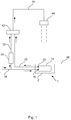
- Fig. 1-4 show schematic views illustrating the effect obtained by using the floor drain 1 according to the present invention.
- the dashed lines are water and the straight arrows show the direction of the water flow.
- a shower is shown in fig. 1-4 .
- a shower head 46 is arranged above the floor drain 1 which is arranged in a floor 48.
- the definition of a "floor drain” is a drain that is installed in a floor so that the top of the floor drain is substantially in the same level as the floor surface.
- the floor drain 1 comprises a heat exchanger element 14 arranged inside a drain compartment 2.
- the heat exchanger element 14 is connected with a first connection 16 to a first conduit 18 for fresh water having a first temperature t1 and with a second connection 20 to a second conduit 22 for fresh water having a second temperature t2.
- the first connection 16 and the second connection 20 are arranged inside the drain compartment 2 in order to prevent water leakage outside the drain compartment 2.
- the second conduit 22 for fresh water having a second temperature t2 is further connected to the inlet of a mixer valve 42.
- the mixer valve 42 is further connected to a third conduit 50 for fresh water having a third temperature t3.
- the third conduit 50 for fresh water having a third temperature t3 is further connected to a water heater 44 which in turn is connected to the first conduit 18 for fresh water having a first temperature t1.
- the shower head 46 and the mixer valve 42 are connected to each other by a fourth conduit 51 for fresh water having a fourth temperature t4.
- fresh water having a first temperature t1 is supplied by the first conduit 18 to the heat exchanger element 14 in the floor drain 1 and to the water heater 44. Further, fresh water having a second temperature t2 is supplied by the second conduit 22 and fresh water having a third temperature t3 is supplied by the third conduit 50 to the mixer valve 42. In the mixer valve 42, the fresh water having a second temperature t2 and the fresh water having a third temperature t3 is mixed to supply fresh water having a fourth temperature t4 to the fourth conduit 51 and the shower head 46.
- the first temperature t1 and the second temperature t2 is essentially the same.
- the first temperature t1 and the second temperature t2 can for example be 7 °C.
- the fresh water having a third temperature t3 has been heated by the water heater 44, thus the third temperature t3 is higher than the first temperature t1 and the second temperature t2.
- the third temperature t3 can for example be 60 °C.
- the water supplied by the shower head 46 leaves the floor 48 through the floor drain 1. If the fourth temperature t4 is higher than the first temperature t1, the floor drain's 1 heat exchanger element 14 recuperates a part of the heat energy present in the waste water. (Any changes of the temperature of the water that is supplied by the shower head 46 is disregarded.)
- the fourth temperature t4 can for example be 37 °C.
- the recuperated energy heats the water inside the heat exchanger element 14. This results in that the second temperature t2 is increased (thus the second temperature t2 becomes higher than the first temperature t1) and in that the temperature of the waste water leaving the floor drain 1 is decreased.
- the second temperature t2 can for example be 25 °C and the temperature of the waste water leaving the floor drain 1 can for example also be 25 °C.
- the fresh water having a third temperature t3 now is mixed with the fresh water having a second temperature t2, which second temperature t2 (as mentioned above) has been raised. Therefore less fresh water having a third temperature t3 needs to be used for obtaining fresh water having a constant fourth temperature t4. Thereby energy for heating up water is saved.
- the mixer valve 42 is a thermostatic mixer valve.
- a thermostatic mixer valve controls the relative proportions of hot and cold water, supplied to an outlet of the thermostatic mixer valve, in accordance with user selection of the outlet water temperature and a thermal control system to compensate for changes in the temperature and/or pressure and/or flow rate of the water supplied to an inlet of the thermostatic mixer valve to maintain the desired constant outlet water temperature.
- the mixer valve 42 can also be a mechanical mixer valve.
- a mechanical mixer valve cannot automatically compensate for changes in the temperature and/or pressure and/or flow rate of the water supplied to an inlet of the mechanical mixer valve. If the mixer valve 42 is a mechanical mixer valve, the user of the shower has to adjust the mixer valve 42 to compensate for changes in the temperature and/or pressure and/or flow rate of the water supplied to the inlet of the mechanical mixer valve to maintain a desired constant outlet water temperature.
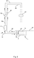
- a mixer valve 42 is exactly the same as fig. 1 except from that fig. 1 shows a mixer valve 42, a fourth conduit 51 and a shower head 46 and fig. 2 shows two separate water valves 40, 52 and a mixing element 54.
- One water valve 52 is connected to the third conduit 50 for fresh water having a third temperature t3 and the other water valve 40 is connected to the second conduit 22 for fresh water having a second temperature t2.
- a mixing element 54 for example a funnel, to mix the water supplied by the second conduit 22 for fresh water having a second temperature t2 and the third conduit 50 for fresh water having a third temperature t3.
- the water valves 40, 52 are connected after the water heater 44 and the heat exchanger element 14. It is also possible, in for example pressure less systems, to connect the water valves 40, 52 before the water heater 44 and the heat exchanger element 14 (this is not shown).
- fig. 1 the recuperated energy is used to preheat water supplied to the mixer valve 42 and in fig. 2 the recuperated energy is used to preheat water supplied to the inlet of the water valve 40. It is also possible to preheat water supplied to the water heater 44. This is shown in fig. 3 .
- Fig. 1 and fig. 3 is exactly the same except from that the water heater 44 is connected to the first conduit 18 for fresh water having a first temperature t1 in fig. 1 and that the water heater 44 is connected to the second conduit 22 for fresh water having a second temperature t2 in fig. 3 . Further, it is also possible to preheat water supplied to both the mixer valve 42 and the water heater 44. This is shown in fig. 4.
- Fig 4 is exactly the same as fig. 3 except from that both the mixer valve 42 and the water heater 44 is connected to the second conduit 22 for fresh water having a second temperature t2 in fig. 4 and that the mixer valve 42 is not connected to the second conduit 22 for fresh water having a second temperature t2 in fig. 3 . It is also possible to preheat water supplied to both the water valve 40 and the water heater 44 (this is not shown). The preheated water is often used for showering or washing, therefore the fresh water having a first temperature t1 advantageously is tap water.
- the tap water can be potable water or process water.
- Fig. 1-4 show, as mentioned above, that the first conduit 18 is connected to the heat exchanger element 14 with the first connection 16 and that the second conduit 22 is connected to the heat exchanger element 14 with the second connection 20.
- the first connection 16 and the second connection 20 are, as mentioned above, arranged inside the drain compartment 2. Thus, there are no connections connecting the heat exchanger element 14 to the first conduit 18 and to the second conduit 22 outside the drain compartment 2.
- the second conduit 22 is continuous between the second connection 20 and the inlet of a mixer valve 42 in Fig. 1 and Fig. 4 , between the second connection 20 and the water valve 40 in Fig. 2 and between the second connection 20 and the water heater 44 in Fig. 3 and Fig. 4 .
- the second conduit 22 is continuous between the second connection 20 and the inlet of a mixer valve 42 in Fig. 1 and Fig. 4 , between the second connection 20 and the water valve 40 in Fig. 2 and between the second connection 20 and the water heater 44 in Fig. 3 and Fig. 4
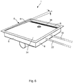
- Fig. 5 shows a perspective view of the floor drain 1, wherein the floor drain 1 is exploded and fig. 6 shows a perspective view of the floor drain 1, wherein the floor drain 1 is assembled.
- the floor drain 1 comprises the drain compartment 2 having a bottom 4, four sides 6 and an open upper portion 8. The sides 6 and the bottom 4 together define a space 10 to collect waste water.
- the floor drain 1 further comprises a heat exchanger element 14, receivable in the space 10 of the drain compartment 2, for transferring heat present in the waste water to the fresh water inside the heat exchanger element 14.
- the bottom 4 of the drain compartment 2 comprises an opening 11. The opening 11 assures that the waste water in the drain compartment 2 is emptied when the floor drain 1 is not used.
- the heat exchanger element 14 is connected with a first connection 16 to the first conduit 18 for fresh water having a first temperature t1 and with the second connection 20 to a second conduit 22 for fresh water having a second temperature t2.
- One side 6 of the drain compartment 2 comprises two openings 56, 56' (shown in Fig. 5 ).
- the first conduit 18 is arranged through the opening 56 and the second conduit 22 is arranged through the opening 56'. It is also possible to arrange the first conduit 18 through the opening 56' and to arrange the second conduit 22 through the opening 56.
- the first conduit 18 and the second conduit 22 are thereby arranged both inside the drain compartment 2 and outside the drain compartment 2 (i.e. inside the floor 48).
- the dashed lines in Fig. 6-8 show the extension of the first conduit 18 and the second conduit 22.
- a sealing (not shown) is arranged between the first conduit 18 and the opening 56 and a further sealing (not shown) is arranged between the second conduit 22 and the opening 56' so that no water can exit from the drain compartment 2, through the openings 56, 56' and into the floor 48.
- a pipe-in-pipe (also called PiP) is a pipe inserted inside a protective conduit pipe. If pipe-in-pipes are used, the outer protective conduit pipes function as sealings against the openings 56, 56'.
- the fresh water entering the heat exchanger element 14 has the first temperature t1 and the fresh water exiting the heat exchanger element 14 has the second temperature t2.
- the fresh water inside the heat exchanger element 14 will absorb energy, from the waste water inside the drain compartment 2, when passing through the heat exchanger element 14 and as a result the second temperature t2 is raised.
- the second temperature t2 becomes higher than the first temperature t1.
- the first connection 16 and the second connection 20 are arranged inside the space 10 of the drain compartment 2.
- the first connection 16 and the second connection 20 can comprise couplings or be welded connections.
- the couplings can for example be swivel couplings.
- a swivel coupling is a coupling between two parts enabling one to revolve without turning the other. If the first connection 16 and the second connection 20 are arranged as swivelling couplings, the heat exchanger element 14 is allowed to be pivoted between a first position p1 and a second position p2. Thereby the first connection 16 and the second connection 20 can be flexible connections.
- the conduits 18, 22 may be made of a stiff material, such as copper or steel.
- the heat exchanger element 14 is preferably made of a material with a high thermal conductivity and a high corrosion resistance, for example copper, to achieve high heat exchange efficiency between the waste water in the drain compartment 2 and the fresh water inside the heat exchanger element 14.
- the drain compartment 2 further comprises a partition wall 25 removably arranged within the space 10 of the drain compartment 2 and under the heat exchanger element 14.
- the partition wall 25 comprises at least one waste water outlet 12, 13 and a drain control unit 26 having walls 28 encircling a waste water outlet 12.
- the walls 28 are protruding upward from the partition wall 25 and the walls 28 are also protruding above the heat exchanger element 14 when the heat exchanger element 14 is arranged in a first position p1.
- the first position p1 is described further below.
- the ability to empty the drain compartment 2 also reduces the risk of mold formation in the waste water in the space 10 of the drain compartment 2 and thereby also the risk of obnoxious smells from the floor drain 1 is reduced.
- the floor drain 1 further comprises a waste water guiding element 34 removably arranged within the space 10 of the drain compartment 2 and above the heat exchanger element 14.
- the waste water guiding element 34 is arranged to slope downwards towards the heat exchanger element 14 with an angle ⁇ in relation to the open upper portion 8 of the drain compartment 2.
- the angle ⁇ is preferably between about 0,01° and about 15°.
- the waste water guiding element 34 is provided with second openings 36 via which waste water is arranged to enter the space 10 of the drain compartment 2.
- the second openings 36 are arranged in a row in a lowermost part of the waste water guiding element 34. It is preferable that the size of the second openings 36 is not too large to prevent foreign substances from flowing into the drain compartment 2.
- the second openings 36 for waste water in the waste water guiding element 34 is orientated in relation to the waste water outlets 12, 13 in the partition wall 25 such that flow of waste water in the space 10 of the drain compartment 2 is directed in a direction essentially opposite to the direction of the fresh water in the heat exchanger element 14.
- the heat exchanger element 14 is operated in counter flow. The best efficiency of a liquid-liquid heat exchanger is obtained if the two liquids, between which energy is transferred, flow in opposite directions.
- the partition wall 25 and/or the water guiding element 34 may be corrugated in order to guide waste water in suitable directions in between different parts of the heat exchanger element 14.
- the floor drain 1 further comprises a cover 30 removably arranged upon the open upper portion 8 of the drain compartment 2 and provided with first openings 32 via which waste water is arranged to enter the space 10 of the drain compartment 2.
- the first openings 32 for waste water in the cover 30 are preferably orientated in relation to the waste water outlets 12, 13 in the partition wall 25 such that flow of waste water in the space 10 of the drain compartment 2 is directed in a direction essentially opposite to the direction of the fresh water in the heat exchanger element 14. In such way the heat exchanger element 14 is operated in counter flow.
- the floor drain 1 comprises a waste water guiding element 34
- the first openings 32 for waste water in the cover 30 are preferably arranged over the whole waste water guiding element 34. In such way waste water is easily drained from the floor in which the floor drain 1 is arranged.
- the floor drain 1 can comprise a drain trap (not shown) in connection to the waste water outlets 12, 13.
- the drain trap can be arranged in the opening 11. If the floor drain 1 does not comprise a drain trap it is called a scupper.
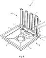
- the heat exchanger element 14 is pivotably arranged between a first position p1 and a second position p2.
- the first position p1 is a position wherein the whole heat exchanger element 14 is received within the drain compartment 2, which is shown in fig. 7 .
- the second position p2 is a position wherein the whole heat exchanger element 14 is not received within the drain compartment 2, which is shown in fig. 8 .
- the heat exchanger element 14 can be pivotably arranged by using for example a first conduit 18 for fresh water having a first temperature t1 comprising a flexible material and a second conduit 22 for fresh water having a second temperature t2 comprising a flexible material. The flexible material will flex when the heat exchanger element 14 is pivoted between the positions p1 and p2.
- the heat exchanger element 14 is pivotable about an axis A, which axis A is substantially parallel with one straight side 6 of the drain compartment 2. It is possible for the floor drain 1 to have several straight sides 6 and it is also possible for the floor drain 1 to not have any straight sides 6, for example if the floor drain 1 has a round shape.
- the heat exchanger element 14 is arranged in the first position p1.
- the cover 30, the partition wall 25 and the waste water guiding element 34 are removed from the floor drain 1 and the heat exchanger element 14 is pivoted from the first position p1 to the second position p2. Then it is possible to easily clean the cover 30, the partition wall 25, the waste water guiding element 34 and the heat exchanger element 14. Thereby it is also possible to access a drain trap (not shown) if provided in the opening 11.
Claims (13)
- Siphon de sol (1), comprenant un compartiment de siphon (2) ayant un fond (4), au moins un côté (6) et une partie supérieure ouverte (8), dans lequel le fond (4) et l'au moins un côté (6) définissent ensemble un espace (10) pour collecter des eaux usées et dans lequel le fond (4) comprend une ouverture (11) pour un siphon, comprenant en outre un élément d'échangeur de chaleur (14), pouvant être reçu dans l'espace (10) du compartiment de siphon (2), pour transférer la chaleur présente dans les eaux usées à de l'eau douce, lequel élément d'échangeur de chaleur (14) est pourvu d'un premier raccordement (16) et d'un deuxième raccordement (20), dans lequel le premier raccordement (16) et le deuxième raccordement (20) sont agencés à l'intérieur de l'espace (10) du compartiment de siphon (2), et un premier conduit (18) pour l'eau douce est raccordé au premier raccordement (16) et en ce qu'un deuxième conduit (22) pour l'eau douce est raccordé au deuxième raccordement (20), le premier conduit (18) est agencé pour comprendre de l'eau douce ayant une première température (t1) et en ce que le deuxième conduit (22) est agencé pour comprendre de l'eau douce ayant une deuxième température (t2), l'élément d'échangeur de chaleur (14) est agencé de manière pivotante entre une première position (p1) et une deuxième position (p2), caractérisé en ce que le siphon de sol (1) comprend en outre une paroi de séparation (25) agencée de façon amovible à l'intérieur de l'espace (10) du compartiment de siphon (2) et comprenant au moins une sortie d'eaux usées (12, 13) et une unité de commande de siphon (26) ayant des parois (28) encerclant l'au moins une sortie d'eaux usées (12), dans lequel les parois (28) font saillie vers le haut à partir de la paroi de séparation (25) et dans lequel les parois (28) font saillie au-dessus de l'élément d'échangeur de chaleur (14) lorsque l'élément d'échangeur de chaleur (14) est agencé dans la première position (p1).
- Siphon de sol selon l'une quelconque des revendications précédentes, caractérisé en ce que le compartiment de siphon (2) comprend au moins un côté droit (6).
- Siphon de sol selon l'une quelconque des revendications précédentes, caractérisé en ce que l'élément d'échangeur de chaleur (14) peut pivoter autour d'un axe (A), lequel axe (A) est sensiblement parallèle à l'au moins un côté droit (6) du compartiment de siphon (2).
- Siphon de sol selon l'une quelconque des revendications précédentes, caractérisé en ce que le premier conduit (18) pour l'eau douce ayant une première température (t1) et le deuxième conduit (22) pour l'eau douce ayant une deuxième température (t2) comprennent un matériau flexible.
- Siphon de sol selon l'une quelconque des revendications précédentes, caractérisé en ce que le siphon de sol (1) comprend en outre un couvercle (30) agencé de manière amovible sur la partie supérieure ouverte (8) du compartiment de siphon (2) et pourvu d'au moins une première ouverture (32) par laquelle des eaux usées peuvent entrer dans l'espace (10) du compartiment de siphon (2).
- Siphon de sol selon la revendication 5, caractérisé en ce que la première ouverture (32) pour les eaux usées dans le couvercle (30) est orientée par rapport à l'au moins une sortie d'eaux usées (12, 13) dans la paroi de séparation (25) de telle sorte que l'écoulement des eaux usées dans l'espace (10) du compartiment de siphon (2) soit dirigé dans une direction essentiellement opposée à la direction de l'eau douce dans l'élément d'échangeur de chaleur (14).
- Siphon de sol selon l'une quelconque des revendications 5 ou 6, caractérisé en ce que le siphon de sol (1) comprend en outre un élément de guidage des eaux usées (34) agencé de manière amovible à l'intérieur de l'espace (10) du compartiment de siphon (2) et agencé en pente vers le bas vers l'élément d'échangeur de chaleur (14), avec un angle (α) par rapport à la partie supérieure ouverte (8) du compartiment de siphon (2), et pourvu d'au moins une deuxième ouverture (36) par laquelle les eaux usées peuvent entrer dans l'espace (10) du compartiment de siphon (2), dans lequel l'au moins une deuxième ouverture (36) est agencée dans une partie la plus inférieure de l'élément de guidage des eaux usées (34).
- Siphon de sol selon la revendication 7, caractérisé en ce que l'au moins une deuxième ouverture (36) pour les eaux usées dans l'élément de guidage des eaux usées (34) est orientée par rapport à l'au moins une sortie d'eaux usées (12, 13) dans la paroi de séparation (25) de telle sorte que l'écoulement des eaux usées dans l'espace (10) du compartiment de siphon (2) soit dirigé dans une direction essentiellement opposée à la direction de l'eau douce dans l'élément d'échangeur de chaleur (14).
- Siphon de sol selon la revendication 7 ou 8, caractérisé en ce que l'angle (α) est de préférence compris entre environ 0,01° et environ 15°.
- Siphon de sol selon l'une quelconque des revendications 7 à 9, caractérisé en ce qu'une pluralité de deuxièmes ouvertures (36) sont agencées en une rangée.
- Siphon de sol selon l'une quelconque des revendications précédentes, caractérisé en ce que le siphon de sol (1) comprend en outre un siphon agencé en raccordement avec l'au moins une sortie d'eaux usées (12, 13).
- Siphon de sol selon l'une quelconque des revendications précédentes, caractérisé en ce que l'eau douce à l'intérieur de l'élément d'échangeur de chaleur (14) est de l'eau du robinet.
- Siphon de sol selon l'une quelconque des revendications précédentes, caractérisé en ce que le deuxième conduit (22) pour l'eau douce ayant une deuxième température (t2) est raccordé à une vanne d'eau (40) ou une vanne mélangeuse (42) et/ou un chauffe-eau (44).
Applications Claiming Priority (2)
| Application Number | Priority Date | Filing Date | Title |
|---|---|---|---|
| SE1450630 | 2014-05-27 | ||
| PCT/SE2015/050528 WO2015183155A1 (fr) | 2014-05-27 | 2015-05-12 | Siphon de sol |
Publications (3)
| Publication Number | Publication Date |
|---|---|
| EP3149253A1 EP3149253A1 (fr) | 2017-04-05 |
| EP3149253A4 EP3149253A4 (fr) | 2018-02-28 |
| EP3149253B1 true EP3149253B1 (fr) | 2019-08-14 |
Family
ID=54699352
Family Applications (1)
| Application Number | Title | Priority Date | Filing Date |
|---|---|---|---|
| EP15799808.9A Active EP3149253B1 (fr) | 2014-05-27 | 2015-05-12 | Siphon de sol |
Country Status (5)
| Country | Link |
|---|---|
| US (1) | US20170198982A1 (fr) |
| EP (1) | EP3149253B1 (fr) |
| CA (1) | CA2950268A1 (fr) |
| DK (1) | DK3149253T3 (fr) |
| WO (1) | WO2015183155A1 (fr) |
Families Citing this family (21)
| Publication number | Priority date | Publication date | Assignee | Title |
|---|---|---|---|---|
| CH709194A2 (de) * | 2014-01-17 | 2015-07-31 | Joulia Ag | Wärmetauscher für eine Dusche oder Badewanne. |
| ES2615633T3 (es) * | 2014-06-05 | 2017-06-07 | Alfa Laval Corporate Ab | Conjunto de descarga |
| CN106197075B (zh) * | 2016-07-30 | 2018-01-30 | 浙江天诚中央空调工程有限公司 | 一种浴室废热回收装置以及使用该装置的废热回收方法 |
| CN106759804B (zh) * | 2016-12-22 | 2019-04-05 | 安徽理工大学 | 一种利用沐浴废水重力势能和热能的地漏 |
| CN106759814B (zh) * | 2017-01-24 | 2022-10-28 | 宁波高新区大维卫浴用品有限公司 | 一种回收废水热能的地漏及其配合结构 |
| US10006645B1 (en) * | 2017-01-27 | 2018-06-26 | Paul A. Howard | Greywater heat recovery with warm side agitation |
| EP3376120A1 (fr) * | 2017-03-14 | 2018-09-19 | Nederlandse Organisatie voor toegepast- natuurwetenschappelijk onderzoek TNO | Système de douche |
| DE112018005023T5 (de) * | 2017-09-28 | 2020-07-09 | Lixil Corporation | Warmwasserversorgungssystem |
| CN109974475B (zh) * | 2017-12-28 | 2024-04-16 | 中冶置业集团有限公司 | 一种废水余热的回收装置 |
| PL234930B1 (pl) * | 2018-02-27 | 2020-05-18 | Politechnika Rzeszowska Im Ignacego Lukasiewicza | Poziomy prysznicowy wymiennik ciepła |
| US10921015B2 (en) * | 2018-08-28 | 2021-02-16 | Johnson Controls Technology Company | Systems and methods for adjustment of heat exchanger position |
| CN108978800B (zh) * | 2018-08-31 | 2021-05-04 | 富山阀门实业(东台)有限公司 | 一种卫生间用多阀门控制装置 |
| CN109707130B (zh) * | 2018-12-28 | 2020-02-21 | 中冶置业集团有限公司 | 集成式热回收地板装置 |
| CN109610567B (zh) * | 2018-12-28 | 2020-01-17 | 中冶置业集团有限公司 | 卫生间淋浴余热回收系统 |
| CN110514030A (zh) * | 2019-07-11 | 2019-11-29 | 武汉奇竹科技有限公司 | 一种超节能热水器 |
| USD987043S1 (en) * | 2019-10-23 | 2023-05-23 | Brandon Turk | Drain outlet |
| USD942594S1 (en) * | 2019-11-13 | 2022-02-01 | Everhard Industries Pty Ltd | Drain grate |
| FR3106878B1 (fr) * | 2020-02-05 | 2022-12-02 | Tineko | Echangeur de chaleur notamment pour bac à douche |
| WO2022124952A1 (fr) * | 2020-12-07 | 2022-06-16 | Idéhuset Gasellen I Varberg Ab | Échangeur de chaleur pour un compartiment de vidange, et système échangeur de chaleur |
| DK181342B8 (en) | 2021-12-07 | 2023-08-21 | Knl Holding Hjoerring Aps | NEW HEAT EXCHANGER WATER LOCK |
| ES1295473Y (es) * | 2022-05-02 | 2023-01-31 | Cerian Shower S L | Sistema recuperador de calor para el agua de una ducha, bañera o similar |
Family Cites Families (11)
| Publication number | Priority date | Publication date | Assignee | Title |
|---|---|---|---|---|
| IT1028131B (it) * | 1974-03-06 | 1979-01-30 | Madeira Fernando Lopes | Apparecchio sanitario comprendente una vasca per doccia e un bidet |
| DD260414A3 (de) * | 1986-06-13 | 1988-09-28 | Bauakademie Ddr | Waermeuebertrager zur rueckgewinnung von duschabwasserwaerme |
| GB2376517B (en) * | 2001-04-21 | 2003-05-07 | Lubor Schiller | Energy recovery system |
| FR2868796B1 (fr) * | 2004-04-09 | 2007-08-03 | Cao Fao Solutions | Installation sanitaire comp0rtant un dispositif de recuperation d'energie a echangeur thermique |
| AU2007202401A1 (en) * | 2007-05-25 | 2008-12-11 | Fix-A-Tap Australia Pty Limited | A water saving sink pipe plug |
| GB0802486D0 (en) * | 2008-02-12 | 2008-03-19 | Gilbert Patrick C | Warm water economy device |
| CH700393A1 (de) * | 2009-02-06 | 2010-08-13 | Creaholic Sa | Wärmetauscher. |
| KR100971774B1 (ko) * | 2009-04-22 | 2010-07-21 | 주식회사 고명에너텍 | 폐온수를 이용한 폐열회수 장치 |
| EP2363676A1 (fr) * | 2010-03-03 | 2011-09-07 | Ayma AB | Échangeur thermique |
| CH705186A2 (de) * | 2011-06-17 | 2012-12-31 | Joulia Ag | Duschwanne mit einem Wärmetauscher und Verfahren zur Herstellung einer Duschwanne. |
| FR2986020A1 (fr) * | 2012-01-23 | 2013-07-26 | Audren Vanzalk | Systeme de douche a recuperateur d'energie amovible |
-
2015
- 2015-05-12 WO PCT/SE2015/050528 patent/WO2015183155A1/fr active Application Filing
- 2015-05-12 DK DK15799808T patent/DK3149253T3/da active
- 2015-05-12 EP EP15799808.9A patent/EP3149253B1/fr active Active
- 2015-05-12 US US15/313,808 patent/US20170198982A1/en not_active Abandoned
- 2015-05-12 CA CA2950268A patent/CA2950268A1/fr not_active Abandoned
Non-Patent Citations (1)
| Title |
|---|
| None * |
Also Published As
| Publication number | Publication date |
|---|---|
| US20170198982A1 (en) | 2017-07-13 |
| DK3149253T3 (da) | 2019-11-04 |
| EP3149253A1 (fr) | 2017-04-05 |
| EP3149253A4 (fr) | 2018-02-28 |
| WO2015183155A1 (fr) | 2015-12-03 |
| CA2950268A1 (fr) | 2015-12-03 |
Similar Documents
| Publication | Publication Date | Title |
|---|---|---|
| EP3149253B1 (fr) | Siphon de sol | |
| US8104532B2 (en) | Shower heat exchanger with clog-removable drain | |
| US7849530B2 (en) | Waste-water heat recovery system | |
| JP5571581B2 (ja) | 熱交換器 | |
| US20080240692A1 (en) | Heat recovery device | |
| CN102954717B (zh) | 热交换器、包括热交换器的能源回收装置及能源回收系统 | |
| GB2416829A (en) | A heat exchange unit utilising waste water to heat cold incoming mains water | |
| WO2020066110A1 (fr) | Système d'alimentation en eau chaude | |
| NL1038387C2 (nl) | Afvoergoot voorzien van een warmtewisselaar en douchebak of douchecabine voorzien van een dergelijke afvoergoot. | |
| US9777932B2 (en) | System for energy recovery and cleaning of heat exchangers in shower applications | |
| EP3596397B1 (fr) | Système de douche | |
| GB2342146A (en) | Heat exchanger | |
| CA2775456C (fr) | Echangeur de chaleur de douche avec avaloir permettant le retrait des obstructions | |
| WO2015185257A1 (fr) | Ensemble de chasse | |
| AU2004289516B2 (en) | Water distribution system | |
| KR101418072B1 (ko) | 욕실 폐열 회수시스템 | |
| US20240052621A1 (en) | A shower drain system and a shower or shower cabin | |
| WO2023104270A1 (fr) | Échangeur de chaleur à pot de purge | |
| CA1154554A (fr) | Mitigeur de douche | |
| FI65487C (fi) | Anordning foer tillvaratagning av vaerme av avfallsvatten | |
| CZ15983U1 (cs) | Zapojení koupelnového výměníku | |
| JP2020069458A (ja) | 洗浄機の排熱回収システム | |
| CZ26629U1 (cs) | Koupelnový deskový výměník | |
| JP2005097912A (ja) | 融雪装置 | |
| GB2530660A (en) | Heat recovery for grey water systems |
Legal Events
| Date | Code | Title | Description |
|---|---|---|---|
| STAA | Information on the status of an ep patent application or granted ep patent |
Free format text: STATUS: THE INTERNATIONAL PUBLICATION HAS BEEN MADE |
|
| PUAI | Public reference made under article 153(3) epc to a published international application that has entered the european phase |
Free format text: ORIGINAL CODE: 0009012 |
|
| STAA | Information on the status of an ep patent application or granted ep patent |
Free format text: STATUS: REQUEST FOR EXAMINATION WAS MADE |
|
| 17P | Request for examination filed |
Effective date: 20161115 |
|
| AK | Designated contracting states |
Kind code of ref document: A1 Designated state(s): AL AT BE BG CH CY CZ DE DK EE ES FI FR GB GR HR HU IE IS IT LI LT LU LV MC MK MT NL NO PL PT RO RS SE SI SK SM TR |
|
| AX | Request for extension of the european patent |
Extension state: BA ME |
|
| DAV | Request for validation of the european patent (deleted) | ||
| DAX | Request for extension of the european patent (deleted) | ||
| A4 | Supplementary search report drawn up and despatched |
Effective date: 20180126 |
|
| RIC1 | Information provided on ipc code assigned before grant |
Ipc: E03F 5/04 20060101AFI20180122BHEP Ipc: A47K 1/14 20060101ALI20180122BHEP Ipc: E03C 1/22 20060101ALI20180122BHEP Ipc: F24D 17/00 20060101ALI20180122BHEP Ipc: F28D 3/02 20060101ALI20180122BHEP Ipc: E03C 1/00 20060101ALI20180122BHEP Ipc: F28D 7/08 20060101ALI20180122BHEP Ipc: F28D 21/00 20060101ALI20180122BHEP Ipc: A47K 3/40 20060101ALI20180122BHEP |
|
| GRAP | Despatch of communication of intention to grant a patent |
Free format text: ORIGINAL CODE: EPIDOSNIGR1 |
|
| STAA | Information on the status of an ep patent application or granted ep patent |
Free format text: STATUS: GRANT OF PATENT IS INTENDED |
|
| GRAJ | Information related to disapproval of communication of intention to grant by the applicant or resumption of examination proceedings by the epo deleted |
Free format text: ORIGINAL CODE: EPIDOSDIGR1 |
|
| GRAP | Despatch of communication of intention to grant a patent |
Free format text: ORIGINAL CODE: EPIDOSNIGR1 |
|
| INTG | Intention to grant announced |
Effective date: 20181123 |
|
| RIN1 | Information on inventor provided before grant (corrected) |
Inventor name: TOERNQVIST, HANS Inventor name: TOERNQUIST, LARS |
|
| GRAJ | Information related to disapproval of communication of intention to grant by the applicant or resumption of examination proceedings by the epo deleted |
Free format text: ORIGINAL CODE: EPIDOSDIGR1 |
|
| INTG | Intention to grant announced |
Effective date: 20181204 |
|
| GRAP | Despatch of communication of intention to grant a patent |
Free format text: ORIGINAL CODE: EPIDOSNIGR1 |
|
| GRAJ | Information related to disapproval of communication of intention to grant by the applicant or resumption of examination proceedings by the epo deleted |
Free format text: ORIGINAL CODE: EPIDOSDIGR1 |
|
| STAA | Information on the status of an ep patent application or granted ep patent |
Free format text: STATUS: REQUEST FOR EXAMINATION WAS MADE |
|
| INTG | Intention to grant announced |
Effective date: 20190108 |
|
| INTC | Intention to grant announced (deleted) | ||
| GRAP | Despatch of communication of intention to grant a patent |
Free format text: ORIGINAL CODE: EPIDOSNIGR1 |
|
| STAA | Information on the status of an ep patent application or granted ep patent |
Free format text: STATUS: GRANT OF PATENT IS INTENDED |
|
| INTG | Intention to grant announced |
Effective date: 20190320 |
|
| GRAS | Grant fee paid |
Free format text: ORIGINAL CODE: EPIDOSNIGR3 |
|
| GRAA | (expected) grant |
Free format text: ORIGINAL CODE: 0009210 |
|
| STAA | Information on the status of an ep patent application or granted ep patent |
Free format text: STATUS: THE PATENT HAS BEEN GRANTED |
|
| AK | Designated contracting states |
Kind code of ref document: B1 Designated state(s): AL AT BE BG CH CY CZ DE DK EE ES FI FR GB GR HR HU IE IS IT LI LT LU LV MC MK MT NL NO PL PT RO RS SE SI SK SM TR |
|
| REG | Reference to a national code |
Ref country code: GB Ref legal event code: FG4D |
|
| REG | Reference to a national code |
Ref country code: CH Ref legal event code: EP Ref country code: AT Ref legal event code: REF Ref document number: 1167199 Country of ref document: AT Kind code of ref document: T Effective date: 20190815 |
|
| REG | Reference to a national code |
Ref country code: IE Ref legal event code: FG4D |
|
| REG | Reference to a national code |
Ref country code: DE Ref legal event code: R096 Ref document number: 602015035934 Country of ref document: DE |
|
| REG | Reference to a national code |
Ref country code: CH Ref legal event code: NV Representative=s name: TR-IP CONSULTING LLC, CH |
|
| REG | Reference to a national code |
Ref country code: DK Ref legal event code: T3 Effective date: 20191030 |
|
| REG | Reference to a national code |
Ref country code: SE Ref legal event code: TRGR |
|
| REG | Reference to a national code |
Ref country code: NL Ref legal event code: FP |
|
| REG | Reference to a national code |
Ref country code: LT Ref legal event code: MG4D |
|
| PG25 | Lapsed in a contracting state [announced via postgrant information from national office to epo] |
Ref country code: FI Free format text: LAPSE BECAUSE OF FAILURE TO SUBMIT A TRANSLATION OF THE DESCRIPTION OR TO PAY THE FEE WITHIN THE PRESCRIBED TIME-LIMIT Effective date: 20190814 Ref country code: LT Free format text: LAPSE BECAUSE OF FAILURE TO SUBMIT A TRANSLATION OF THE DESCRIPTION OR TO PAY THE FEE WITHIN THE PRESCRIBED TIME-LIMIT Effective date: 20190814 Ref country code: BG Free format text: LAPSE BECAUSE OF FAILURE TO SUBMIT A TRANSLATION OF THE DESCRIPTION OR TO PAY THE FEE WITHIN THE PRESCRIBED TIME-LIMIT Effective date: 20191114 Ref country code: PT Free format text: LAPSE BECAUSE OF FAILURE TO SUBMIT A TRANSLATION OF THE DESCRIPTION OR TO PAY THE FEE WITHIN THE PRESCRIBED TIME-LIMIT Effective date: 20191216 Ref country code: NO Free format text: LAPSE BECAUSE OF FAILURE TO SUBMIT A TRANSLATION OF THE DESCRIPTION OR TO PAY THE FEE WITHIN THE PRESCRIBED TIME-LIMIT Effective date: 20191114 Ref country code: HR Free format text: LAPSE BECAUSE OF FAILURE TO SUBMIT A TRANSLATION OF THE DESCRIPTION OR TO PAY THE FEE WITHIN THE PRESCRIBED TIME-LIMIT Effective date: 20190814 |
|
| REG | Reference to a national code |
Ref country code: CH Ref legal event code: PCAR Free format text: NEW ADDRESS: ROUTE DU COUTSET 18, 1485 NUVILLY (CH) |
|
| REG | Reference to a national code |
Ref country code: AT Ref legal event code: MK05 Ref document number: 1167199 Country of ref document: AT Kind code of ref document: T Effective date: 20190814 |
|
| PG25 | Lapsed in a contracting state [announced via postgrant information from national office to epo] |
Ref country code: RS Free format text: LAPSE BECAUSE OF FAILURE TO SUBMIT A TRANSLATION OF THE DESCRIPTION OR TO PAY THE FEE WITHIN THE PRESCRIBED TIME-LIMIT Effective date: 20190814 Ref country code: GR Free format text: LAPSE BECAUSE OF FAILURE TO SUBMIT A TRANSLATION OF THE DESCRIPTION OR TO PAY THE FEE WITHIN THE PRESCRIBED TIME-LIMIT Effective date: 20191115 Ref country code: IS Free format text: LAPSE BECAUSE OF FAILURE TO SUBMIT A TRANSLATION OF THE DESCRIPTION OR TO PAY THE FEE WITHIN THE PRESCRIBED TIME-LIMIT Effective date: 20191214 Ref country code: AL Free format text: LAPSE BECAUSE OF FAILURE TO SUBMIT A TRANSLATION OF THE DESCRIPTION OR TO PAY THE FEE WITHIN THE PRESCRIBED TIME-LIMIT Effective date: 20190814 Ref country code: ES Free format text: LAPSE BECAUSE OF FAILURE TO SUBMIT A TRANSLATION OF THE DESCRIPTION OR TO PAY THE FEE WITHIN THE PRESCRIBED TIME-LIMIT Effective date: 20190814 Ref country code: LV Free format text: LAPSE BECAUSE OF FAILURE TO SUBMIT A TRANSLATION OF THE DESCRIPTION OR TO PAY THE FEE WITHIN THE PRESCRIBED TIME-LIMIT Effective date: 20190814 |
|
| PG25 | Lapsed in a contracting state [announced via postgrant information from national office to epo] |
Ref country code: TR Free format text: LAPSE BECAUSE OF FAILURE TO SUBMIT A TRANSLATION OF THE DESCRIPTION OR TO PAY THE FEE WITHIN THE PRESCRIBED TIME-LIMIT Effective date: 20190814 |
|
| PG25 | Lapsed in a contracting state [announced via postgrant information from national office to epo] |
Ref country code: PL Free format text: LAPSE BECAUSE OF FAILURE TO SUBMIT A TRANSLATION OF THE DESCRIPTION OR TO PAY THE FEE WITHIN THE PRESCRIBED TIME-LIMIT Effective date: 20190814 Ref country code: EE Free format text: LAPSE BECAUSE OF FAILURE TO SUBMIT A TRANSLATION OF THE DESCRIPTION OR TO PAY THE FEE WITHIN THE PRESCRIBED TIME-LIMIT Effective date: 20190814 Ref country code: AT Free format text: LAPSE BECAUSE OF FAILURE TO SUBMIT A TRANSLATION OF THE DESCRIPTION OR TO PAY THE FEE WITHIN THE PRESCRIBED TIME-LIMIT Effective date: 20190814 Ref country code: IT Free format text: LAPSE BECAUSE OF FAILURE TO SUBMIT A TRANSLATION OF THE DESCRIPTION OR TO PAY THE FEE WITHIN THE PRESCRIBED TIME-LIMIT Effective date: 20190814 Ref country code: RO Free format text: LAPSE BECAUSE OF FAILURE TO SUBMIT A TRANSLATION OF THE DESCRIPTION OR TO PAY THE FEE WITHIN THE PRESCRIBED TIME-LIMIT Effective date: 20190814 |
|
| PG25 | Lapsed in a contracting state [announced via postgrant information from national office to epo] |
Ref country code: SK Free format text: LAPSE BECAUSE OF FAILURE TO SUBMIT A TRANSLATION OF THE DESCRIPTION OR TO PAY THE FEE WITHIN THE PRESCRIBED TIME-LIMIT Effective date: 20190814 Ref country code: CZ Free format text: LAPSE BECAUSE OF FAILURE TO SUBMIT A TRANSLATION OF THE DESCRIPTION OR TO PAY THE FEE WITHIN THE PRESCRIBED TIME-LIMIT Effective date: 20190814 Ref country code: IS Free format text: LAPSE BECAUSE OF FAILURE TO SUBMIT A TRANSLATION OF THE DESCRIPTION OR TO PAY THE FEE WITHIN THE PRESCRIBED TIME-LIMIT Effective date: 20200224 Ref country code: SM Free format text: LAPSE BECAUSE OF FAILURE TO SUBMIT A TRANSLATION OF THE DESCRIPTION OR TO PAY THE FEE WITHIN THE PRESCRIBED TIME-LIMIT Effective date: 20190814 |
|
| REG | Reference to a national code |
Ref country code: DE Ref legal event code: R097 Ref document number: 602015035934 Country of ref document: DE |
|
| PLBE | No opposition filed within time limit |
Free format text: ORIGINAL CODE: 0009261 |
|
| STAA | Information on the status of an ep patent application or granted ep patent |
Free format text: STATUS: NO OPPOSITION FILED WITHIN TIME LIMIT |
|
| PG2D | Information on lapse in contracting state deleted |
Ref country code: IS |
|
| PGFP | Annual fee paid to national office [announced via postgrant information from national office to epo] |
Ref country code: CH Payment date: 20200615 Year of fee payment: 6 Ref country code: DE Payment date: 20200509 Year of fee payment: 6 Ref country code: NL Payment date: 20200428 Year of fee payment: 6 Ref country code: DK Payment date: 20200504 Year of fee payment: 6 |
|
| 26N | No opposition filed |
Effective date: 20200603 |
|
| PG25 | Lapsed in a contracting state [announced via postgrant information from national office to epo] |
Ref country code: SI Free format text: LAPSE BECAUSE OF FAILURE TO SUBMIT A TRANSLATION OF THE DESCRIPTION OR TO PAY THE FEE WITHIN THE PRESCRIBED TIME-LIMIT Effective date: 20190814 |
|
| PGFP | Annual fee paid to national office [announced via postgrant information from national office to epo] |
Ref country code: SE Payment date: 20200429 Year of fee payment: 6 Ref country code: BE Payment date: 20200429 Year of fee payment: 6 |
|
| PG25 | Lapsed in a contracting state [announced via postgrant information from national office to epo] |
Ref country code: MC Free format text: LAPSE BECAUSE OF FAILURE TO SUBMIT A TRANSLATION OF THE DESCRIPTION OR TO PAY THE FEE WITHIN THE PRESCRIBED TIME-LIMIT Effective date: 20190814 |
|
| GBPC | Gb: european patent ceased through non-payment of renewal fee |
Effective date: 20200512 |
|
| PG25 | Lapsed in a contracting state [announced via postgrant information from national office to epo] |
Ref country code: LU Free format text: LAPSE BECAUSE OF NON-PAYMENT OF DUE FEES Effective date: 20200512 |
|
| PG25 | Lapsed in a contracting state [announced via postgrant information from national office to epo] |
Ref country code: GB Free format text: LAPSE BECAUSE OF NON-PAYMENT OF DUE FEES Effective date: 20200512 Ref country code: IE Free format text: LAPSE BECAUSE OF NON-PAYMENT OF DUE FEES Effective date: 20200512 Ref country code: FR Free format text: LAPSE BECAUSE OF NON-PAYMENT OF DUE FEES Effective date: 20200531 |
|
| REG | Reference to a national code |
Ref country code: DE Ref legal event code: R119 Ref document number: 602015035934 Country of ref document: DE |
|
| REG | Reference to a national code |
Ref country code: DK Ref legal event code: EBP Effective date: 20210531 |
|
| REG | Reference to a national code |
Ref country code: SE Ref legal event code: EUG |
|
| REG | Reference to a national code |
Ref country code: CH Ref legal event code: PL |
|
| REG | Reference to a national code |
Ref country code: NL Ref legal event code: MM Effective date: 20210601 |
|
| PG25 | Lapsed in a contracting state [announced via postgrant information from national office to epo] |
Ref country code: SE Free format text: LAPSE BECAUSE OF NON-PAYMENT OF DUE FEES Effective date: 20210513 Ref country code: CH Free format text: LAPSE BECAUSE OF NON-PAYMENT OF DUE FEES Effective date: 20210531 Ref country code: LI Free format text: LAPSE BECAUSE OF NON-PAYMENT OF DUE FEES Effective date: 20210531 |
|
| REG | Reference to a national code |
Ref country code: BE Ref legal event code: MM Effective date: 20210531 |
|
| PG25 | Lapsed in a contracting state [announced via postgrant information from national office to epo] |
Ref country code: DK Free format text: LAPSE BECAUSE OF NON-PAYMENT OF DUE FEES Effective date: 20210531 Ref country code: DE Free format text: LAPSE BECAUSE OF NON-PAYMENT OF DUE FEES Effective date: 20211201 |
|
| PG25 | Lapsed in a contracting state [announced via postgrant information from national office to epo] |
Ref country code: NL Free format text: LAPSE BECAUSE OF NON-PAYMENT OF DUE FEES Effective date: 20210601 Ref country code: MT Free format text: LAPSE BECAUSE OF FAILURE TO SUBMIT A TRANSLATION OF THE DESCRIPTION OR TO PAY THE FEE WITHIN THE PRESCRIBED TIME-LIMIT Effective date: 20190814 Ref country code: CY Free format text: LAPSE BECAUSE OF FAILURE TO SUBMIT A TRANSLATION OF THE DESCRIPTION OR TO PAY THE FEE WITHIN THE PRESCRIBED TIME-LIMIT Effective date: 20190814 |
|
| PG25 | Lapsed in a contracting state [announced via postgrant information from national office to epo] |
Ref country code: MK Free format text: LAPSE BECAUSE OF FAILURE TO SUBMIT A TRANSLATION OF THE DESCRIPTION OR TO PAY THE FEE WITHIN THE PRESCRIBED TIME-LIMIT Effective date: 20190814 |
|
| PG25 | Lapsed in a contracting state [announced via postgrant information from national office to epo] |
Ref country code: BE Free format text: LAPSE BECAUSE OF NON-PAYMENT OF DUE FEES Effective date: 20210531 |