EP3147927A1 - Electric switching device - Google Patents
Electric switching device Download PDFInfo
- Publication number
- EP3147927A1 EP3147927A1 EP16185799.0A EP16185799A EP3147927A1 EP 3147927 A1 EP3147927 A1 EP 3147927A1 EP 16185799 A EP16185799 A EP 16185799A EP 3147927 A1 EP3147927 A1 EP 3147927A1
- Authority
- EP
- European Patent Office
- Prior art keywords
- terminal contact
- switching device
- connection
- electrical conductor
- contact busbar
- Prior art date
- Legal status (The legal status is an assumption and is not a legal conclusion. Google has not performed a legal analysis and makes no representation as to the accuracy of the status listed.)
- Granted
Links
- 239000004020 conductor Substances 0.000 claims abstract description 47
- 239000011810 insulating material Substances 0.000 claims abstract description 4
- 238000005452 bending Methods 0.000 claims description 8
- 230000002093 peripheral effect Effects 0.000 claims description 4
- 230000037431 insertion Effects 0.000 description 8
- 238000003780 insertion Methods 0.000 description 8
- 238000006073 displacement reaction Methods 0.000 description 2
- 238000009413 insulation Methods 0.000 description 2
- 239000002184 metal Substances 0.000 description 2
- 230000004308 accommodation Effects 0.000 description 1
- 238000005516 engineering process Methods 0.000 description 1
- WABPQHHGFIMREM-UHFFFAOYSA-N lead(0) Chemical compound [Pb] WABPQHHGFIMREM-UHFFFAOYSA-N 0.000 description 1
- 239000000463 material Substances 0.000 description 1
- 239000007769 metal material Substances 0.000 description 1
- 230000000630 rising effect Effects 0.000 description 1
- IHQKEDIOMGYHEB-UHFFFAOYSA-M sodium dimethylarsinate Chemical class [Na+].C[As](C)([O-])=O IHQKEDIOMGYHEB-UHFFFAOYSA-M 0.000 description 1
- 125000006850 spacer group Chemical group 0.000 description 1
Images

Classifications
-
- H—ELECTRICITY
- H01—ELECTRIC ELEMENTS
- H01H—ELECTRIC SWITCHES; RELAYS; SELECTORS; EMERGENCY PROTECTIVE DEVICES
- H01H71/00—Details of the protective switches or relays covered by groups H01H73/00 - H01H83/00
- H01H71/08—Terminals; Connections
-
- H—ELECTRICITY
- H01—ELECTRIC ELEMENTS
- H01H—ELECTRIC SWITCHES; RELAYS; SELECTORS; EMERGENCY PROTECTIVE DEVICES
- H01H1/00—Contacts
- H01H1/58—Electric connections to or between contacts; Terminals
-
- H—ELECTRICITY
- H01—ELECTRIC ELEMENTS
- H01H—ELECTRIC SWITCHES; RELAYS; SELECTORS; EMERGENCY PROTECTIVE DEVICES
- H01H73/00—Protective overload circuit-breaking switches in which excess current opens the contacts by automatic release of mechanical energy stored by previous operation of a hand reset mechanism
- H01H73/02—Details
- H01H73/20—Terminals; Connections
Definitions
- the invention relates to an electrical, at least single-pole switching device with a housing made of insulating material, each pole having at least one incoming and one outgoing terminal contact, and each of the terminal contacts a terminal contact busbar and first connection means for connecting at least a first external electrical conductor wherein at least one of the terminal contacts has second connection means for the connection of a second electrical conductor.
- the invention relates to an electrical switching device according to the preamble of claim 1.
- the invention relates to switching devices such as contactors motor protection switch, circuit breaker or circuit breaker or the like.
- switching devices such as contactors motor protection switch, circuit breaker or circuit breaker or the like.
- programmable switching devices such as programmable logic controllers or programmable relays are contemplated within the scope of the invention.
- Conventional switching devices such as contactors have input and output side for each pole to be switched on a terminal contact in the form of a fixed contact.
- the associated fixed contacts are connected or disconnected via a contact bridge driven by a magnetic drive.
- the externally accessible fixed contact terminals are usually on laterally accessible screw, which can be screwed or loosened from the top of the device, or formed by side or top accessible and also from the side or from above releasable spring clamp connections.
- each pole at least an incoming and an outgoing terminal contact
- each of the terminal contacts has first connection means for the connection of a first external electrical conductor
- each of the terminal contacts has second connection means for the connection of a second electrical conductor.
- the first connection means are in the form of conventional screw terminal connections, spring clamp connections (eg, cage spring clamp terminals), insulation displacement connections or other connection means.
- the additional second connection means are formed as a hole receiving in the formed as a tongue-like terminal lug contact carrier.
- the second electrical connection conductor must therefore be inserted from the housing side deep into the housing to meet in the hole receptacle of the second connection means. Misjures are often possible.
- the hole receiver removes conductor material from the terminal contact bus bar, so in the area of the hole receiver, the electrical resistance of the terminal contact bus bar is increased, which is unfavorable.
- the object of the invention is to provide a switching device which is improved with regard to the connection technology of the second electrical conductor.
- the second connection means are formed with a clamping member for clamping receiving the second electrical conductor, wherein the clamping member from the terminal contact bus bar in the direction of an outer side of the housing spaced and with the terminal contact busbar is electrically and mechanically connected.
- the clamping member for clamping receiving the second electrical conductor is thus offset from the terminal contact busbar and brought closer to the outside of the housing.
- the second connection means are formed with at least two resilient arms which are mounted on the terminal contact busbar and a receiving space for the second external electrical conductor at least partially limit, and the second electrical conductor is inserted into the receiving space between the two resilient arms and can be clamped therein due to the restoring spring force of the resilient arms.
- the insertion end of the second electrical connection conductor is clamped between the two resilient arms, so that a secure mechanical and electrical connection between the second connection means and the second electrical conductor can be produced without the insertion end of the second electrical conductor would have special spring-clamping properties. It can be a simple stripped conductor end between the inventively provided resilient arms are inserted and clamped therebetween, only due to the restoring spring force of the two resilient arms.
- each resilient arm is attached to a longitudinally extending holding beam attached to the terminal contact bus bar and rising above the terminal contact bus bar.
- the second connection means is thus lifted out of the plane of the first connection means, it is located above the first connection means. This is advantageous if, for example, the second electrical connection conductors are to be introduced from above into the switching device and the first connection means from the front.
- each resilient arm is resiliently pivotable in a plane perpendicular to the longitudinal extension direction of its holding beam.
- the resilient arms are designed as elongated clamping bars and arranged parallel to each other and parallel to a broad side of the terminal contact busbar.
- the retaining bars are mounted on opposite narrow sides of the terminal contact busbar.
- the holding beam with the attached resilient arm forms an L-shape.
- the amount of torsional rigidity of the holding beam in the direction of pivoting of the resilient arm greater than the amount of bending stiffness in bending in the direction of the longitudinal extension of the resilient arm.
- the retaining bar is a plate-shaped, one-sided in a recess in the narrow side of the terminal contact busbar attached, aligned with its broad side parallel to the longitudinal extension direction of the terminal contact bus bar, formed.
- the clamping member is formed as a hole receiving closed peripheral contour for receiving provided with resilient elements plug contacts of the second electrical conductor.
- the hole receptacle is offset from the terminal contact busbar, for example formed as a metal disc with a hole receiving, wherein the metal disc is electrically and mechanically connected by means of at least one serving as a spacer to the terminal contact bus bar with the terminal contact busbar.
- the resilient elements for establishing the required contact force are included in this embodiment at the end of the second lead wire.
- the first connection means are designed as synchronklemman gleich or as Federklemman gleich or as insulation displacement connection.
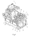
- FIG. 1 shows as an example of an inventive electrical switching device, a three-pole motor protection switch 1 with a housing 2 made of insulating material.
- the housing 2 is in the view of FIG. 1 partially removed and gives the view of the three access-side terminal contacts 4, 4 ', 4 ", which are each assigned to one of the three poles 3, 3', 3" of the motor protection switch.
- Corresponding outgoing connection contacts are located on the viewer of the FIG. 1
- Each of the connection contacts 4, 4 ', 4 " has a connection contact busbar 5 and first connection means 6, 6', 6" for the connection of at least one first external electrical conductor.
- the second electrical conductor may be a connecting conductor to an attachment or an accessory that is mechanically connected to the housing 2 of the switching device.
- the second electrical conductor is via the second connection means 8 mechanically and electrically well and firmly, and yet releasably connected to the terminal 4 and the pole 3 of the switching device 1 connected or connected.
- the second connection means 8 made of a highly electrically conductive material.
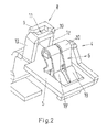
- FIG. 2 shows details of the terminal contact 4. As a central component, it has an approximately plate-shaped terminal contact busbar 5. In the viewer facing, front part of the terminal contact busbar 5, this has a rectangular recess. At an edge of this recess, the clamping spring 20 of the first connection means 6 is supported.
- the first connection means 6 corresponds to a so far known in principle plug-in spring contact.
- connection contact busbar 8 Located in the longitudinal extension direction of the terminal contact busbar behind the first connection means 6 is the second connection means 8. These are on opposite narrow sides 15, 16 of the connection contact busbar. 5 Holding bar 12, 13 attached. Each retaining bar 12, 13 is formed as a plate-shaped, on one side in a recess 17 in the narrow side 15, 16 of the terminal contact bus bar 5 mounted, aligned with its broad side 18 parallel to the longitudinal direction of the terminal contact busbar 5, beam.
- Each retaining bar 12, 13 thus depends on the terminal contact busbar 5.
- the second connection means 8 is thus lifted out of the plane of the first connection means 6, it is located above the first connection means 6. This is advantageous if, for example, the second electrical connection conductors 7 are to be inserted from above into the switching device 1 and the first connection means from the front or diagonally from the front.
- each have a resilient arm 9, 10 is attached.
- the holding bar 13 forms with the attached resilient arm 10 an L-shape.
- the resilient arms 9, 10 are formed as elongated clamping bars and arranged parallel to each other and parallel to a broad side 14 of the terminal contact busbar 5. Each resilient arm 9, 10 is thereby in a plane perpendicular to the longitudinal direction of its support beam 12, 13 resiliently pivotable.
- the rectangular cross-section of the retaining bars 12, 13 and the attachment with its broad side 18 parallel to the longitudinal direction of the terminal contact 5 has the consequence that the amount of torsional stiffness of the support bar 12, 13 in the direction of pivoting the resilient arm 9, 10 is greater than that Amount of bending stiffness in bending in the direction of the longitudinal extent of the resilient arm 9, 10th
- the two resilient arms 9, 10 thus form part of the lateral boundary of a receiving space 11 for the second external electrical conductor 7.
- the receiving space 11 has in this example a rectangular cross-section, wherein its longitudinal direction is oriented perpendicular to the longitudinal extension direction of the terminal contact busbar 5.
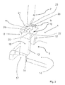
- the second electrical conductor 7 is inserted into the receiving space 11 between the two resilient arms 9, 10, see FIG. 3 ,
- the cross section of the insertion end of the second electrical conductor 7 is greater than the cross section of the receiving space.
- the peripheral contour of the introductory part of the second electrical conductor 7 wider than the distance between the two mutually facing longitudinally extended inner edges 22, 21 of the two resilient arms 9, 10, but narrower than the distance between the two mutually facing inner edges 23, 24 of the short L-legs 25, 26 forming free ends of the two retaining bars 12, 13th
- the second electrical conductor pushes apart only the two resilient arms 9, 10. Because the amount of torsional rigidity of the support beam 12, 13 in the direction of pivoting of the resilient arm 9, 10 is greater than the amount of bending stiffness in bending in the direction of the longitudinal extent of the resilient arm 9, 10 will be only the two resilient arms 9, 10th swivel against its restoring spring force and absorb the second electrical conductor between them. Due to the restoring spring force of the resilient arms 9, 10 then the insertion end of the second electrical conductor between the two resilient arms 9, 10 is clamped, thus mechanically held and electrically well connected, see FIG. 4 ,
- connection contact 4 with the connection contact busbar 5 and the second connection means 8, as described above can be produced very cheaply in one piece as a stamped bent part made of an electrically highly conductive, preferably metallic material.
- the second embodiment, in which the clamping member is formed as a hole receiver with closed circumferential contour is not shown here by figures.
Abstract
Die Erfindung betrifft ein elektrisches, mindestens einpolig ausgebildetes Schaltgerät (1) mit einem Gehäuse (2) aus Isolierstoffmaterial, wobei jeder Pol (3, 3', 3") zumindest einen ankommenden und einen abgehenden Anschlusskontakt (4, 4', 4") aufweist, und jeder der Anschlusskontakte (4, 4', 4") eine Anschlusskontakt-Stromschiene (5) und erste Anschlussmittel (6, 6', 6") für den Anschluss mindestens eines ersten externen elektrischen Leiters aufweist, wobei zumindest einer der Anschlusskontakte (4) zweite Anschlussmittel (8) für den Anschluss eines zweiten elektrischen Leiters (7) aufweist. Die zweiten Anschlussmittel (8) sind mit einem Klemmorgan zur klemmenden Aufnahme des zweiten elektrischen Leiters (7) ausgebildet, wobei das Klemmorgan von der Anschlusskontakt-Stromschiene (5) in Richtung auf eine Außenseite des Gehäuses (2) hin beabstandet und mit der Anschlusskontakt-Stromschiene (5) elektrisch und mechanisch verbunden ist.

Description
Die Erfindung geht aus von einem elektrischen, mindestens einpolig ausgebildeten Schaltgerät mit einem Gehäuse aus Isolierstoffmaterial, wobei jeder Pol zumindest einen ankommenden und einen abgehenden Anschlusskontakt aufweist, und jeder der Anschlusskontakte eine Anschlusskontakt-Stromschiene und erste Anschlussmittel für den Anschluss mindestens eines ersten externen elektrischen Leiters aufweist, wobei zumindest einer der Anschlusskontakte zweite Anschlussmittel für den Anschluss eines zweiten elektrischen Leiters aufweist.The invention relates to an electrical, at least single-pole switching device with a housing made of insulating material, each pole having at least one incoming and one outgoing terminal contact, and each of the terminal contacts a terminal contact busbar and first connection means for connecting at least a first external electrical conductor wherein at least one of the terminal contacts has second connection means for the connection of a second electrical conductor.
Die Erfindung betrifft ein elektrisches Schaltgerät nach dem Oberbegriff des Anspruches 1. Insbesondere betrifft die Erfindung Schaltgeräte wie Schütze Motorschutzschalter, Leitungsschutzschalter oder Leistungsschalter oder dergleichen. Aber auch programmierbare Schaltgeräte wie speicherprogrammierbare Steuerungen oder programmierbare Relais sind im Anwendungsbereich der Erfindung angedacht.The invention relates to an electrical switching device according to the preamble of claim 1. In particular, the invention relates to switching devices such as contactors motor protection switch, circuit breaker or circuit breaker or the like. But also programmable switching devices such as programmable logic controllers or programmable relays are contemplated within the scope of the invention.
Herkömmliche Schaltgeräte wie zum Beispiel Schütze weisen eingangs- und ausgangsseitig für jeden zu schaltenden Pol einen Anschlusskontakt in Form eines Festkontaktes auf. Zum Zwecke der Verbindung beziehungsweise Unterbrechung werden die zugehörigen Festkontakte über eine durch einen Magnetantrieb angetriebene Kontaktbrücke verbunden bzw. getrennt. Bei derartigen Geräten sind die von außen zugänglichen Festkontaktanschlüsse in der Regel über seitlich zugängliche Schraubanschlüsse, die von der Geräteoberseite verschraubt bzw. gelöst werden können, oder durch seitlich oder von oben zugängliche und auch wieder von der Seite oder von oben lösbare Federklemmanschlüsse gebildet.Conventional switching devices such as contactors have input and output side for each pole to be switched on a terminal contact in the form of a fixed contact. For the purpose of connection or interruption, the associated fixed contacts are connected or disconnected via a contact bridge driven by a magnetic drive. In such devices, the externally accessible fixed contact terminals are usually on laterally accessible screw, which can be screwed or loosened from the top of the device, or formed by side or top accessible and also from the side or from above releasable spring clamp connections.
Aus der
Die ersten Anschlussmittel sind in Form herkömmlicher Schraubklemmanschlüsse, Federklemmanschlüsse (z. B. Käfig-Zugfederklemmanschlüsse), Schneidklemmanschlüsse oder anderer Anschlussmittel gebildet. Die zusätzlichen zweiten Anschlussmittel sind als Lochaufnahme in dem als zungenartige Anschlussfahne ausgebildeten Kontaktträger ausgeformt. Der zweite elektrische Anschlussleiter muss daher von der Gehäuseseite her tief in das Gehäuse eingeführt werden, um in die Lochaufnahme des zweiten Anschlussmittels zu treffen. Fehlsteckungen sind dabei häufig möglich. Die Lochaufnahme entfernt Leitermaterial aus der Anschlusskontakt-Stromschiene, daher ist in dem Bereich der Lochaufnahme der elektrische Widerstand der Anschlusskontakt-Stromschiene erhöht, was ungünstig ist..The first connection means are in the form of conventional screw terminal connections, spring clamp connections (eg, cage spring clamp terminals), insulation displacement connections or other connection means. The additional second connection means are formed as a hole receiving in the formed as a tongue-like terminal lug contact carrier. The second electrical connection conductor must therefore be inserted from the housing side deep into the housing to meet in the hole receptacle of the second connection means. Misjures are often possible. The hole receiver removes conductor material from the terminal contact bus bar, so in the area of the hole receiver, the electrical resistance of the terminal contact bus bar is increased, which is unfavorable.
Aufgabe der Erfindung ist es ein Schaltgerät zu schaffen, welches im Hinblick auf die Anschlusstechnik des zweiten elektrischen Leiters verbessert ist..The object of the invention is to provide a switching device which is improved with regard to the connection technology of the second electrical conductor.
Die Aufgabe wird gelöst durch ein Schaltgerät mit den Merkmalen des Anspruchs 1. Erfindungsgemäß sind die zweiten Anschlussmittel mit einem Klemmorgan zur klemmenden Aufnahme des zweiten elektrischen Leiters ausgebildet, wobei das Klemmorgan von der Anschlusskontakt-Stromschiene in Richtung auf eine Außenseite des Gehäuses hin beabstandet und mit der Anschlusskontakt-Stromschiene elektrisch und mechanisch verbunden ist. Das Klemmorgan zur klemmenden Aufnahme des zweiten elektrischen Leiters ist also abgesetzt von der Anschlusskontakt-Stromschiene und näher an die Außenseite des Gehäuses herangeführt. Damit wird der Abstand von einer in der Außenseite des Gehäuses befindlichen Einführöffnung verringert, und das Einführen eines zweiten Anschlussleiters wird vereinfacht, denn es wird einfacher, die Lochaufnahme zu treffen, das Risiko von Fehlsteckungen wird verringert. Der Leiterquerschnitt der Anschlusskontakt-Stromschiene im Bereich des Klemmorgans bleibt unverändert, und damit auch der elektrische Widerstand der Anschlusskontakt-Stromschiene.The object is achieved by a switching device having the features of claim 1. According to the invention, the second connection means are formed with a clamping member for clamping receiving the second electrical conductor, wherein the clamping member from the terminal contact bus bar in the direction of an outer side of the housing spaced and with the terminal contact busbar is electrically and mechanically connected. The clamping member for clamping receiving the second electrical conductor is thus offset from the terminal contact busbar and brought closer to the outside of the housing. Thus, the distance from an insertion opening located in the outside of the housing is reduced, and the insertion of a second connecting conductor is simplified, because it is easier to meet the hole recording, the risk of mishaps is reduced. The conductor cross-section of the terminal contact busbar in the region of the clamping member remains unchanged, and thus also the electrical resistance of the terminal contact busbar.
Gemäß einer vorteilhaften Ausführungsform der Erfindung sind die zweiten Anschlussmittel mit wenigstens zwei federnden Armen ausgebildet, die an der Anschlusskontakt-Stromschiene angebracht sind und einen Aufnahmeraum für den zweiten externen elektrischen Leiter zumindest teilweise begrenzen, und der zweite elektrische Leiter ist in den Aufnahmeraum zwischen den beiden federnden Armen einführbar und aufgrund der rückstellenden Federkraft der federnden Arme darin festklemmbar.According to an advantageous embodiment of the invention, the second connection means are formed with at least two resilient arms which are mounted on the terminal contact busbar and a receiving space for the second external electrical conductor at least partially limit, and the second electrical conductor is inserted into the receiving space between the two resilient arms and can be clamped therein due to the restoring spring force of the resilient arms.
Das Einführende des zweiten elektrischen Anschlussleiters wird zwischen den beiden federnden Armen festgeklemmt, so dass eine sichere mechanische und elektrische verbindungzwischen den zweiten Anschlussmitteln und dem zweiten elektrischen Leiter herstellbar ist, ohne dass das Einführende des zweiten elektrischen Leiters besondere federklemmende Eigenschaften aufweisen müsste. Es kann ein einfaches abisoliertes Leiterende zwischen die erfindungsgemäß vorgesehenen federnden Arme eingeführt werden und wird dazwischen festgeklemmt, nur aufgrund der rückstellenden Federkraft der beiden federnden Arme.The insertion end of the second electrical connection conductor is clamped between the two resilient arms, so that a secure mechanical and electrical connection between the second connection means and the second electrical conductor can be produced without the insertion end of the second electrical conductor would have special spring-clamping properties. It can be a simple stripped conductor end between the inventively provided resilient arms are inserted and clamped therebetween, only due to the restoring spring force of the two resilient arms.
Gemäß einer vorteilhaften Ausführungsform der Erfindung ist jeder federnde Arm an einem an der Anschlusskontakt-Stromschiene befestigten, sich über der Anschlusskontakt-Stromschiene aufrichtenden, längserstreckten Halte-Balken angebracht. Das zweite Anschlussmittel ist damit aus der Ebene der ersten Anschlussmittel herausgehoben, es befindet sich oberhalb der ersten Anschlussmittel. Das ist vorteilhaft, wenn beispielsweise die zweiten elektrischen Anschlussleiter von oben in das Schaltgerät eingeführt werden sollen und die ersten Anschlussmittel von vorne.According to an advantageous embodiment of the invention, each resilient arm is attached to a longitudinally extending holding beam attached to the terminal contact bus bar and rising above the terminal contact bus bar. The second connection means is thus lifted out of the plane of the first connection means, it is located above the first connection means. This is advantageous if, for example, the second electrical connection conductors are to be introduced from above into the switching device and the first connection means from the front.
Gemäß einer vorteilhaften Ausführungsform der Erfindung ist jeder federnde Arm in einer Ebene senkrecht zu der Längserstreckungsrichtung seines Halte- Balkens federnd verschwenkbar.According to an advantageous embodiment of the invention, each resilient arm is resiliently pivotable in a plane perpendicular to the longitudinal extension direction of its holding beam.
Gemäß einer vorteilhaften Ausführungsform der Erfindung sind die federnden Arme als längserstreckte Klemm-Balken ausgebildet und parallel zueinander und parallel zu einer Breitseite der Anschlusskontakt-Stromschiene angeordnet.According to an advantageous embodiment of the invention, the resilient arms are designed as elongated clamping bars and arranged parallel to each other and parallel to a broad side of the terminal contact busbar.
Gemäß einer vorteilhaften Ausführungsform der Erfindung sind die Halte-Balken an sich gegenüberliegenden Schmalseiten der Anschlusskontakt-Stromschiene angebracht.According to an advantageous embodiment of the invention, the retaining bars are mounted on opposite narrow sides of the terminal contact busbar.
Gemäß einer vorteilhaften Ausführungsform der Erfindung bildet der Haltebalken mit dem daran angebrachten federnden Arm eine L-Form.According to an advantageous embodiment of the invention, the holding beam with the attached resilient arm forms an L-shape.
Gemäß einer vorteilhaften Ausführungsform der Erfindung ist der Betrag der Torsionssteifigkeit des Haltebalkens in Richtung der Verschwenkung des federnden Arms größer als der Betrag der Biegesteifigkeit bei Verbiegung in Richtung der Längserstreckung des federnden Arms.According to an advantageous embodiment of the invention, the amount of torsional rigidity of the holding beam in the direction of pivoting of the resilient arm greater than the amount of bending stiffness in bending in the direction of the longitudinal extension of the resilient arm.
Gemäß einer vorteilhaften Ausführungsform der Erfindung ist der Halte-Balken ein plattenförmiger, einseitig in einer Ausnehmung in der Schmalseite der Anschlusskontakt-Stromschiene angebrachter, mit seiner Breitseite parallel zu Längserstreckungsrichtung der Anschlusskontakt-Stromschiene ausgerichteter, Balken ausgebildet.According to an advantageous embodiment of the invention, the retaining bar is a plate-shaped, one-sided in a recess in the narrow side of the terminal contact busbar attached, aligned with its broad side parallel to the longitudinal extension direction of the terminal contact bus bar, formed.
Gemäß einer weiteren vorteilhaften Ausführungsform der Erfindung ist das Klemmorgan als eine Lochaufnahme mit geschlossener Umfangskontur ausgebildet für die Aufnahme von mit federnden Elementen versehenen Steckkontakten des zweiten elektrischen Leiters. In dieser Ausführungsform ist die Lochaufnahme abgesetzt von der Anschlusskontakt-Stromschiene, beispielsweise ausgebildet als eine Metallscheibe mit einer Lochaufnahme, wobei die Metallscheibe mittels wenigstens eines als Abstandshalter zu der Anschlusskontakt-Stromschiene dienenden Verbindungssteges mit der Anschlusskontakt-Stromschiene elektrisch und mechanisch verbunden ist. Die federnden Elemente zum Aufbau der erforderlichen Kontaktkraft sind bei dieser Ausführungsform an dem Endstück des zweiten Anschlussleiters enthalten.According to a further advantageous embodiment of the invention, the clamping member is formed as a hole receiving closed peripheral contour for receiving provided with resilient elements plug contacts of the second electrical conductor. In this embodiment, the hole receptacle is offset from the terminal contact busbar, for example formed as a metal disc with a hole receiving, wherein the metal disc is electrically and mechanically connected by means of at least one serving as a spacer to the terminal contact bus bar with the terminal contact busbar. The resilient elements for establishing the required contact force are included in this embodiment at the end of the second lead wire.
Gemäß einer vorteilhaften Ausführungsform der Erfindung sind die ersten Anschlussmittel als Schraubklemmanschluss oder als Federklemmanschluss oder als Schneidklemmanschluss ausgebildet.According to an advantageous embodiment of the invention, the first connection means are designed as Schraubklemmanschluss or as Federklemmanschluss or as insulation displacement connection.
Weitere vorteilhafte Ausgestaltungen und Verbesserungen der Erfindung und weitere Vorteile sind in den Unteransprüchen zu entnehmen.
- Figurenbeschreibung:
- Figuren und Beschreibung dienen dem besseren Verständnis des Gegenstands. Gegenstände oder Teile von Gegenständen, die im Wesentlichen gleich oder ähnlich sind, können mit denselben Bezugszeichen versehen sein. Die Figuren sind lediglich eine schematische Darstellung der Erfindung.
- Brief Description:
- Figures and description serve to better understand the subject. Articles or parts of objects which are substantially the same or similar may be given the same reference numerals. The figures are merely a schematic representation of the invention.
Dabei zeigen:
- Fig. 1
- ein erfindungsgemäßes Schaltgerät, mit teilweise entferntem Gehäuse und Ansicht der Anschlusskontakte,
- Fig. 2
- eine Detailansicht eines erfindungsgemäßem Anschlusskontaktes,
- Fig. 3
- eine Detailansicht eines erfindungsgemäßen zweiten Anschlussmittels mit einem zweiten Anschlussleiter vor dem Einführen,
- Fig. 4
- eine Detailansicht eines erfindungsgemäßen zweiten Anschlussmittels mit einem eingeführten zweiten Anschlussleiter.
- Fig. 1
- an inventive switching device, with partially removed housing and view of the terminals,
- Fig. 2
- a detailed view of an inventive terminal contact,
- Fig. 3
- a detailed view of a second connection means according to the invention with a second connection conductor before insertion,
- Fig. 4
- a detailed view of a second connection means according to the invention with an inserted second connection conductor.
Hier im Beispiel hat jeder der Anschlusskontakte 4, 4', 4" zweite Anschlussmittel 8, 8', 8" für den Anschluss eines zweiten elektrischen Leiters 7, siehe
In Längserstreckungsrichtung der Anschlusskontakt-Stromschiene hinter dem ersten Anschlussmittel 6 gelegen befindet sich das zweite Anschlussmittel 8. Dazu sind an sich gegenüberliegenden Schmalseiten 15, 16 der Anschlusskontakt-Stromschiene 5 Halte-Balken 12, 13 angebracht. Jeder Halte-Balken 12, 13 ist als ein plattenförmiger, einseitig in einer Ausnehmung 17 in der Schmalseite 15, 16 der Anschlusskontakt-Stromschiene 5 angebrachter, mit seiner Breitseite 18 parallel zu Längserstreckungsrichtung der Anschlusskontakt-Stromschiene 5 ausgerichteter, Balken ausgebildet.Located in the longitudinal extension direction of the terminal contact busbar behind the first connection means 6 is the second connection means 8. These are on opposite
Jeder Halte-Balken 12, 13 richtet sich somit über der Anschlusskontakt-Stromschiene 5 auf. Das zweite Anschlussmittel 8 ist damit aus der Ebene der ersten Anschlussmittel 6 herausgehoben, es befindet sich oberhalb der ersten Anschlussmittel 6. Das ist vorteilhaft, wenn beispielsweise die zweiten elektrischen Anschlussleiter 7 von oben in das Schaltgerät 1 eingeführt werden sollen und die ersten Anschlussmittel von vorne oder schräg von vorne.Each retaining
Am freien Ende des Haltebalkens 12, 13 ist jeweils ein federnder Arm 9, 10 angebracht. Der Haltebalken 13 bildet mit dem daran angebrachten federnden Arm 10 eine L-Form. Die federnden Arme 9, 10 sind als längserstreckte Klemm-Balken ausgebildet und parallel zueinander und parallel zu einer Breitseite 14 der Anschlusskontakt-Stromschiene 5 angeordnet. Jeder federnde Arm 9, 10 ist dadurch in einer Ebene senkrecht zu der Längserstreckungsrichtung seines Halte- Balkens 12, 13 federnd verschwenkbar.At the free end of the
Der rechteckige Querschnitt der Haltebalken 12, 13 und die Befestigung mit ihrer Breitseite 18 parallel zu der Längserstreckungsrichtung der AnschlusskontaktStromschiene 5 hat zur Folge, dass der Betrag der Torsionssteifigkeit des Haltebalkens 12, 13 in Richtung der Verschwenkung des federnden Arms 9, 10 größer ist als der Betrag der Biegesteifigkeit bei Verbiegung in Richtung der Längserstreckung des federnden Arms 9, 10.The rectangular cross-section of the retaining bars 12, 13 and the attachment with its
Die beiden federnden Armen 9, 10 bilden damit einen Teil der seitlichen Begrenzung eines Aufnahmeraums 11 für den zweiten externen elektrischen Leiter 7. Der Aufnahmeraum 11 hat hier im Beispiel eine rechteckigen Querschnitt, wobei seine Längserstreckungsrichtung senkrecht zur Längserstreckungsrichtung der Anschlusskontakt-Stromschiene 5 orientiert ist.The two
Der zweite elektrische Leiter 7 ist in den Aufnahmeraum 11 zwischen den beiden federnden Armen 9, 10 einführbar, siehe
Beim Einführen drückt daher der zweite elektrische Leiter nur die beiden federnden Arme 9, 10 auseinander. Weil der Betrag der Torsionssteifigkeit des Haltebalkens 12, 13 in Richtung der Verschwenkung des federnden Arms 9, 10 größer ist als der Betrag der Biegesteifigkeit bei Verbiegung in Richtung der Längserstreckung des federnden Arms 9, 10 werden sich dabei nur die beiden federnden Arme 9, 10 entgegen ihrer rückstellenden Federkraft verschwenken und den zweiten elektrischen Leiter so zwischen sich aufnehmen. Aufgrund der rückstellenden Federkraft der federnden Arme 9, 10 ist dann das Einführende des zweiten elektrischen Leiters zwischen den beiden federnden Armen 9, 10 festgeklemmt, somit mechanisch gehalten und elektrisch gut verbunden, siehe
Wenn die Umfangskontur des Einführendes des zweiten elektrischen Leiters auch noch größer wäre als der Abstand der beiden aufeinander zu weisenden Innenkanten 23, 24 der die kurzen L-Schenkel 25, 26 bildenden freien Enden der beiden Halte-Balken 12, 13, dann würden zusätzlich die beiden Haltebalken 12, 13, voneinander weg gebogen, in Richtung senkrecht zu ihren Breitseiten 18. Aufgrund der rückstellenden Federkraft der Haltebalken 12, 13 ergäbe sich dann eine zusätzliche Klemmkraftkomponente, hervorgerufen von den beiden Haltebalken 12, 13.If the circumferential contour of the insertion end of the second electrical conductor would be even greater than the distance between the two mutually facing
Der Anschlusskontakt 4 mit der Anschlusskontaktstromschiene 5 und dem zweiten Anschlussmittel 8, wie oben beschrieben, kann sehr günstig einstückig als StanzBiegeteil aus einem elektrisch gut leitenden, vorzugsweise metallischen Werkstoff hergestellt werden.The connection contact 4 with the
Die zweite Ausführungsform, bei der das Klemmorgan als eine Lochaufnahme mit geschlossener Umfangskontur ausgebildet ist, ist hier nicht durch Figuren dargestellt. Man kann sich dies aber sehr leicht durch Modifizierung der in den
Claims (10)
dadurch gekennzeichnet, dass die zweiten Anschlussmittel (8) mit einem Klemmorgan zur klemmenden Aufnahme des zweiten elektrischen Leiters (7) ausgebildet sind, wobei das Klemmorgan von der Anschlusskontakt-Stromschiene (5) in Richtung auf eine Außenseite des Gehäuses (2) hin beabstandet und mit der Anschlusskontakt-Stromschiene (5) elektrisch und mechanisch verbunden ist.Electrical, at least one pole trained switching device (1) having a housing (2) made of insulating material, each pole (3, 3 ', 3 ") at least one incoming and an outgoing terminal contact (4, 4', 4"), and each the connection contacts (4, 4 ', 4 ") has a connection contact busbar (5) and first connection means (6, 6', 6") for the connection of at least one first external electrical conductor, wherein at least one of the connection contacts (4) second Connecting means (8) for the connection of a second electrical conductor (7),
characterized in that the second connection means (8) with a clamping member for clamping receiving the second electrical conductor (7) are formed, wherein the clamping member of the terminal contact busbar (5) in the direction of an outer side of the housing (2) spaced out and with the terminal contact busbar (5) is electrically and mechanically connected.
Applications Claiming Priority (1)
| Application Number | Priority Date | Filing Date | Title |
|---|---|---|---|
| DE102015116085.4A DE102015116085A1 (en) | 2015-09-23 | 2015-09-23 | Electrical switching device |
Publications (2)
| Publication Number | Publication Date |
|---|---|
| EP3147927A1 true EP3147927A1 (en) | 2017-03-29 |
| EP3147927B1 EP3147927B1 (en) | 2018-08-01 |
Family
ID=56801457
Family Applications (1)
| Application Number | Title | Priority Date | Filing Date |
|---|---|---|---|
| EP16185799.0A Active EP3147927B1 (en) | 2015-09-23 | 2016-08-26 | Electric switching device |
Country Status (3)
| Country | Link |
|---|---|
| EP (1) | EP3147927B1 (en) |
| CN (1) | CN106847625B (en) |
| DE (1) | DE102015116085A1 (en) |
Citations (3)
| Publication number | Priority date | Publication date | Assignee | Title |
|---|---|---|---|---|
| WO1996012292A1 (en) * | 1994-10-18 | 1996-04-25 | Bticino S.P.A. | A miniaturized automatic circuit breaker with a multifunctional terminal and a screen for protection against internal electric arcs |
| DE10236790C1 (en) * | 2002-08-10 | 2003-10-16 | Moeller Gmbh | Electrical switching device has incoming and/or outgoing contacts provided with external electrical lead terminals and second terminals for second electrical conductor |
| WO2006027336A1 (en) * | 2004-09-08 | 2006-03-16 | Siemens Aktiengesellschaft | Switching device comprising plug-in terminals |
Family Cites Families (1)
| Publication number | Priority date | Publication date | Assignee | Title |
|---|---|---|---|---|
| CN102037535A (en) * | 2008-02-05 | 2011-04-27 | 西门子工业公司 | Self-adjusting plug-in line terminal |
-
2015
- 2015-09-23 DE DE102015116085.4A patent/DE102015116085A1/en not_active Withdrawn
-
2016
- 2016-08-26 EP EP16185799.0A patent/EP3147927B1/en active Active
- 2016-09-22 CN CN201610839883.4A patent/CN106847625B/en active Active
Patent Citations (3)
| Publication number | Priority date | Publication date | Assignee | Title |
|---|---|---|---|---|
| WO1996012292A1 (en) * | 1994-10-18 | 1996-04-25 | Bticino S.P.A. | A miniaturized automatic circuit breaker with a multifunctional terminal and a screen for protection against internal electric arcs |
| DE10236790C1 (en) * | 2002-08-10 | 2003-10-16 | Moeller Gmbh | Electrical switching device has incoming and/or outgoing contacts provided with external electrical lead terminals and second terminals for second electrical conductor |
| WO2006027336A1 (en) * | 2004-09-08 | 2006-03-16 | Siemens Aktiengesellschaft | Switching device comprising plug-in terminals |
Also Published As
| Publication number | Publication date |
|---|---|
| CN106847625B (en) | 2020-04-24 |
| EP3147927B1 (en) | 2018-08-01 |
| CN106847625A (en) | 2017-06-13 |
| DE102015116085A1 (en) | 2017-03-23 |
Similar Documents
| Publication | Publication Date | Title |
|---|---|---|
| EP3159974B2 (en) | Electric connecting terminal | |
| EP3324490B1 (en) | Spring clamp contact for connecting an electrical conductor, conductor connection terminal and method for manufacturing a spring clamp contact | |
| DE102010014144C5 (en) | Electrical connection terminal | |
| DE102008017245B4 (en) | Plug-in adapter for an electrical switching device | |
| EP3118938B1 (en) | Connector | |
| EP3342005B1 (en) | Electric terminal block | |
| DE202015102045U1 (en) | Spring-loaded clamping element with pivoting lever | |
| DE102011015697B4 (en) | Counter switching block for an electricity meter and devices with a counter switching block | |
| EP2419966B1 (en) | Spring push terminal | |
| WO2015032516A1 (en) | Wall feed-through device | |
| EP3147927B1 (en) | Electric switching device | |
| EP2489100B1 (en) | Clamping screw with cover and installation switching device | |
| DE202015102561U1 (en) | Conductor terminal | |
| EP0921611B1 (en) | Mains socket and -switch | |
| DE102012202240A1 (en) | Clamping body for a connection terminal | |
| EP0141047A1 (en) | Clamping screws for a strip connector | |
| DE202008004431U1 (en) | Impedance bond | |
| DE102015103113A1 (en) | Disconnect terminal | |
| DE102015121836B4 (en) | Printed circuit board with plug-in contact integrated on the front side as well as power distributors equipped therewith | |
| DE102016110189B4 (en) | Connection device with plug-in terminal | |
| EP3116067B1 (en) | Connecting device with plug-in terminal | |
| EP3118933B1 (en) | Connecting device with plug-in terminal | |
| EP1990879A1 (en) | Single mounting carrier for mounting an overload relay | |
| DE1081536B (en) | Connection clamp for two rigid electrical conductors | |
| WO2006084421A1 (en) | Electromagnetic switch device in particular a contactor |
Legal Events
| Date | Code | Title | Description |
|---|---|---|---|
| PUAI | Public reference made under article 153(3) epc to a published international application that has entered the european phase |
Free format text: ORIGINAL CODE: 0009012 |
|
| AK | Designated contracting states |
Kind code of ref document: A1 Designated state(s): AL AT BE BG CH CY CZ DE DK EE ES FI FR GB GR HR HU IE IS IT LI LT LU LV MC MK MT NL NO PL PT RO RS SE SI SK SM TR |
|
| AX | Request for extension of the european patent |
Extension state: BA ME |
|
| 17P | Request for examination filed |
Effective date: 20170919 |
|
| GRAP | Despatch of communication of intention to grant a patent |
Free format text: ORIGINAL CODE: EPIDOSNIGR1 |
|
| INTG | Intention to grant announced |
Effective date: 20180503 |
|
| GRAS | Grant fee paid |
Free format text: ORIGINAL CODE: EPIDOSNIGR3 |
|
| GRAA | (expected) grant |
Free format text: ORIGINAL CODE: 0009210 |
|
| AK | Designated contracting states |
Kind code of ref document: B1 Designated state(s): AL AT BE BG CH CY CZ DE DK EE ES FI FR GB GR HR HU IE IS IT LI LT LU LV MC MK MT NL NO PL PT RO RS SE SI SK SM TR |
|
| REG | Reference to a national code |
Ref country code: GB Ref legal event code: FG4D Free format text: NOT ENGLISH |
|
| REG | Reference to a national code |
Ref country code: CH Ref legal event code: EP Ref country code: AT Ref legal event code: REF Ref document number: 1025299 Country of ref document: AT Kind code of ref document: T Effective date: 20180815 |
|
| REG | Reference to a national code |
Ref country code: IE Ref legal event code: FG4D Free format text: LANGUAGE OF EP DOCUMENT: GERMAN |
|
| REG | Reference to a national code |
Ref country code: DE Ref legal event code: R096 Ref document number: 502016001579 Country of ref document: DE |
|
| REG | Reference to a national code |
Ref country code: FR Ref legal event code: PLFP Year of fee payment: 3 |
|
| REG | Reference to a national code |
Ref country code: NL Ref legal event code: MP Effective date: 20180801 |
|
| REG | Reference to a national code |
Ref country code: LT Ref legal event code: MG4D |
|
| PG25 | Lapsed in a contracting state [announced via postgrant information from national office to epo] |
Ref country code: LT Free format text: LAPSE BECAUSE OF FAILURE TO SUBMIT A TRANSLATION OF THE DESCRIPTION OR TO PAY THE FEE WITHIN THE PRESCRIBED TIME-LIMIT Effective date: 20180801 Ref country code: RS Free format text: LAPSE BECAUSE OF FAILURE TO SUBMIT A TRANSLATION OF THE DESCRIPTION OR TO PAY THE FEE WITHIN THE PRESCRIBED TIME-LIMIT Effective date: 20180801 Ref country code: FI Free format text: LAPSE BECAUSE OF FAILURE TO SUBMIT A TRANSLATION OF THE DESCRIPTION OR TO PAY THE FEE WITHIN THE PRESCRIBED TIME-LIMIT Effective date: 20180801 Ref country code: SE Free format text: LAPSE BECAUSE OF FAILURE TO SUBMIT A TRANSLATION OF THE DESCRIPTION OR TO PAY THE FEE WITHIN THE PRESCRIBED TIME-LIMIT Effective date: 20180801 Ref country code: PL Free format text: LAPSE BECAUSE OF FAILURE TO SUBMIT A TRANSLATION OF THE DESCRIPTION OR TO PAY THE FEE WITHIN THE PRESCRIBED TIME-LIMIT Effective date: 20180801 Ref country code: NO Free format text: LAPSE BECAUSE OF FAILURE TO SUBMIT A TRANSLATION OF THE DESCRIPTION OR TO PAY THE FEE WITHIN THE PRESCRIBED TIME-LIMIT Effective date: 20181101 Ref country code: GR Free format text: LAPSE BECAUSE OF FAILURE TO SUBMIT A TRANSLATION OF THE DESCRIPTION OR TO PAY THE FEE WITHIN THE PRESCRIBED TIME-LIMIT Effective date: 20181102 Ref country code: NL Free format text: LAPSE BECAUSE OF FAILURE TO SUBMIT A TRANSLATION OF THE DESCRIPTION OR TO PAY THE FEE WITHIN THE PRESCRIBED TIME-LIMIT Effective date: 20180801 Ref country code: IS Free format text: LAPSE BECAUSE OF FAILURE TO SUBMIT A TRANSLATION OF THE DESCRIPTION OR TO PAY THE FEE WITHIN THE PRESCRIBED TIME-LIMIT Effective date: 20181201 Ref country code: BG Free format text: LAPSE BECAUSE OF FAILURE TO SUBMIT A TRANSLATION OF THE DESCRIPTION OR TO PAY THE FEE WITHIN THE PRESCRIBED TIME-LIMIT Effective date: 20181101 |
|
| PG25 | Lapsed in a contracting state [announced via postgrant information from national office to epo] |
Ref country code: HR Free format text: LAPSE BECAUSE OF FAILURE TO SUBMIT A TRANSLATION OF THE DESCRIPTION OR TO PAY THE FEE WITHIN THE PRESCRIBED TIME-LIMIT Effective date: 20180801 Ref country code: AL Free format text: LAPSE BECAUSE OF FAILURE TO SUBMIT A TRANSLATION OF THE DESCRIPTION OR TO PAY THE FEE WITHIN THE PRESCRIBED TIME-LIMIT Effective date: 20180801 Ref country code: LV Free format text: LAPSE BECAUSE OF FAILURE TO SUBMIT A TRANSLATION OF THE DESCRIPTION OR TO PAY THE FEE WITHIN THE PRESCRIBED TIME-LIMIT Effective date: 20180801 |
|
| PG25 | Lapsed in a contracting state [announced via postgrant information from national office to epo] |
Ref country code: IT Free format text: LAPSE BECAUSE OF FAILURE TO SUBMIT A TRANSLATION OF THE DESCRIPTION OR TO PAY THE FEE WITHIN THE PRESCRIBED TIME-LIMIT Effective date: 20180801 Ref country code: ES Free format text: LAPSE BECAUSE OF FAILURE TO SUBMIT A TRANSLATION OF THE DESCRIPTION OR TO PAY THE FEE WITHIN THE PRESCRIBED TIME-LIMIT Effective date: 20180801 Ref country code: CZ Free format text: LAPSE BECAUSE OF FAILURE TO SUBMIT A TRANSLATION OF THE DESCRIPTION OR TO PAY THE FEE WITHIN THE PRESCRIBED TIME-LIMIT Effective date: 20180801 Ref country code: RO Free format text: LAPSE BECAUSE OF FAILURE TO SUBMIT A TRANSLATION OF THE DESCRIPTION OR TO PAY THE FEE WITHIN THE PRESCRIBED TIME-LIMIT Effective date: 20180801 Ref country code: EE Free format text: LAPSE BECAUSE OF FAILURE TO SUBMIT A TRANSLATION OF THE DESCRIPTION OR TO PAY THE FEE WITHIN THE PRESCRIBED TIME-LIMIT Effective date: 20180801 Ref country code: LU Free format text: LAPSE BECAUSE OF NON-PAYMENT OF DUE FEES Effective date: 20180826 Ref country code: MC Free format text: LAPSE BECAUSE OF FAILURE TO SUBMIT A TRANSLATION OF THE DESCRIPTION OR TO PAY THE FEE WITHIN THE PRESCRIBED TIME-LIMIT Effective date: 20180801 |
|
| REG | Reference to a national code |
Ref country code: DE Ref legal event code: R097 Ref document number: 502016001579 Country of ref document: DE |
|
| REG | Reference to a national code |
Ref country code: BE Ref legal event code: MM Effective date: 20180831 |
|
| PG25 | Lapsed in a contracting state [announced via postgrant information from national office to epo] |
Ref country code: DK Free format text: LAPSE BECAUSE OF FAILURE TO SUBMIT A TRANSLATION OF THE DESCRIPTION OR TO PAY THE FEE WITHIN THE PRESCRIBED TIME-LIMIT Effective date: 20180801 Ref country code: SK Free format text: LAPSE BECAUSE OF FAILURE TO SUBMIT A TRANSLATION OF THE DESCRIPTION OR TO PAY THE FEE WITHIN THE PRESCRIBED TIME-LIMIT Effective date: 20180801 Ref country code: SM Free format text: LAPSE BECAUSE OF FAILURE TO SUBMIT A TRANSLATION OF THE DESCRIPTION OR TO PAY THE FEE WITHIN THE PRESCRIBED TIME-LIMIT Effective date: 20180801 |
|
| PLBE | No opposition filed within time limit |
Free format text: ORIGINAL CODE: 0009261 |
|
| STAA | Information on the status of an ep patent application or granted ep patent |
Free format text: STATUS: NO OPPOSITION FILED WITHIN TIME LIMIT |
|
| 26N | No opposition filed |
Effective date: 20190503 |
|
| PG25 | Lapsed in a contracting state [announced via postgrant information from national office to epo] |
Ref country code: BE Free format text: LAPSE BECAUSE OF NON-PAYMENT OF DUE FEES Effective date: 20180831 Ref country code: SI Free format text: LAPSE BECAUSE OF FAILURE TO SUBMIT A TRANSLATION OF THE DESCRIPTION OR TO PAY THE FEE WITHIN THE PRESCRIBED TIME-LIMIT Effective date: 20180801 |
|
| PG25 | Lapsed in a contracting state [announced via postgrant information from national office to epo] |
Ref country code: MT Free format text: LAPSE BECAUSE OF FAILURE TO SUBMIT A TRANSLATION OF THE DESCRIPTION OR TO PAY THE FEE WITHIN THE PRESCRIBED TIME-LIMIT Effective date: 20180801 |
|
| PG25 | Lapsed in a contracting state [announced via postgrant information from national office to epo] |
Ref country code: TR Free format text: LAPSE BECAUSE OF FAILURE TO SUBMIT A TRANSLATION OF THE DESCRIPTION OR TO PAY THE FEE WITHIN THE PRESCRIBED TIME-LIMIT Effective date: 20180801 |
|
| PG25 | Lapsed in a contracting state [announced via postgrant information from national office to epo] |
Ref country code: PT Free format text: LAPSE BECAUSE OF FAILURE TO SUBMIT A TRANSLATION OF THE DESCRIPTION OR TO PAY THE FEE WITHIN THE PRESCRIBED TIME-LIMIT Effective date: 20180801 Ref country code: LI Free format text: LAPSE BECAUSE OF NON-PAYMENT OF DUE FEES Effective date: 20190831 Ref country code: CH Free format text: LAPSE BECAUSE OF NON-PAYMENT OF DUE FEES Effective date: 20190831 |
|
| PG25 | Lapsed in a contracting state [announced via postgrant information from national office to epo] |
Ref country code: HU Free format text: LAPSE BECAUSE OF FAILURE TO SUBMIT A TRANSLATION OF THE DESCRIPTION OR TO PAY THE FEE WITHIN THE PRESCRIBED TIME-LIMIT; INVALID AB INITIO Effective date: 20160826 Ref country code: IE Free format text: LAPSE BECAUSE OF NON-PAYMENT OF DUE FEES Effective date: 20180826 Ref country code: CY Free format text: LAPSE BECAUSE OF FAILURE TO SUBMIT A TRANSLATION OF THE DESCRIPTION OR TO PAY THE FEE WITHIN THE PRESCRIBED TIME-LIMIT Effective date: 20180801 Ref country code: MK Free format text: LAPSE BECAUSE OF NON-PAYMENT OF DUE FEES Effective date: 20180801 |
|
| GBPC | Gb: european patent ceased through non-payment of renewal fee |
Effective date: 20200826 |
|
| PG25 | Lapsed in a contracting state [announced via postgrant information from national office to epo] |
Ref country code: GB Free format text: LAPSE BECAUSE OF NON-PAYMENT OF DUE FEES Effective date: 20200826 |
|
| REG | Reference to a national code |
Ref country code: AT Ref legal event code: MM01 Ref document number: 1025299 Country of ref document: AT Kind code of ref document: T Effective date: 20210826 |
|
| PG25 | Lapsed in a contracting state [announced via postgrant information from national office to epo] |
Ref country code: AT Free format text: LAPSE BECAUSE OF NON-PAYMENT OF DUE FEES Effective date: 20210826 |
|
| PGFP | Annual fee paid to national office [announced via postgrant information from national office to epo] |
Ref country code: FR Payment date: 20230825 Year of fee payment: 8 Ref country code: DE Payment date: 20230821 Year of fee payment: 8 |