EP3147917A1 - Contactless electric power supply device - Google Patents
Contactless electric power supply device Download PDFInfo
- Publication number
- EP3147917A1 EP3147917A1 EP16190391.9A EP16190391A EP3147917A1 EP 3147917 A1 EP3147917 A1 EP 3147917A1 EP 16190391 A EP16190391 A EP 16190391A EP 3147917 A1 EP3147917 A1 EP 3147917A1
- Authority
- EP
- European Patent Office
- Prior art keywords
- core
- power supply
- power receiving
- power
- annular
- Prior art date
- Legal status (The legal status is an assumption and is not a legal conclusion. Google has not performed a legal analysis and makes no representation as to the accuracy of the status listed.)
- Withdrawn
Links
- 229910000831 Steel Inorganic materials 0.000 claims description 6
- 239000010959 steel Substances 0.000 claims description 6
- 239000004020 conductor Substances 0.000 abstract description 5
- XEEYBQQBJWHFJM-UHFFFAOYSA-N Iron Chemical compound [Fe] XEEYBQQBJWHFJM-UHFFFAOYSA-N 0.000 description 12
- 230000005540 biological transmission Effects 0.000 description 10
- 230000004907 flux Effects 0.000 description 8
- 229910052742 iron Inorganic materials 0.000 description 6
- 239000011800 void material Substances 0.000 description 6
- 229910000859 α-Fe Inorganic materials 0.000 description 6
- 239000010410 layer Substances 0.000 description 4
- 238000000034 method Methods 0.000 description 4
- 230000008569 process Effects 0.000 description 4
- 239000000463 material Substances 0.000 description 3
- 230000008859 change Effects 0.000 description 2
- 238000010276 construction Methods 0.000 description 2
- 230000003247 decreasing effect Effects 0.000 description 2
- 230000000694 effects Effects 0.000 description 2
- 230000005674 electromagnetic induction Effects 0.000 description 2
- 239000011810 insulating material Substances 0.000 description 2
- 239000002184 metal Substances 0.000 description 2
- 229910052751 metal Inorganic materials 0.000 description 2
- 238000003825 pressing Methods 0.000 description 2
- 230000009467 reduction Effects 0.000 description 2
- 229910000976 Electrical steel Inorganic materials 0.000 description 1
- 239000013590 bulk material Substances 0.000 description 1
- 230000015556 catabolic process Effects 0.000 description 1
- 238000006731 degradation reaction Methods 0.000 description 1
- 238000005516 engineering process Methods 0.000 description 1
- 239000000696 magnetic material Substances 0.000 description 1
- 238000004519 manufacturing process Methods 0.000 description 1
- 230000010355 oscillation Effects 0.000 description 1
- 230000004044 response Effects 0.000 description 1
- 239000002344 surface layer Substances 0.000 description 1
- 238000004804 winding Methods 0.000 description 1
Images


Classifications
-
- H—ELECTRICITY
- H02—GENERATION; CONVERSION OR DISTRIBUTION OF ELECTRIC POWER
- H02J—CIRCUIT ARRANGEMENTS OR SYSTEMS FOR SUPPLYING OR DISTRIBUTING ELECTRIC POWER; SYSTEMS FOR STORING ELECTRIC ENERGY
- H02J50/00—Circuit arrangements or systems for wireless supply or distribution of electric power
- H02J50/10—Circuit arrangements or systems for wireless supply or distribution of electric power using inductive coupling
-
- H—ELECTRICITY
- H01—ELECTRIC ELEMENTS
- H01F—MAGNETS; INDUCTANCES; TRANSFORMERS; SELECTION OF MATERIALS FOR THEIR MAGNETIC PROPERTIES
- H01F38/00—Adaptations of transformers or inductances for specific applications or functions
- H01F38/14—Inductive couplings
-
- H—ELECTRICITY
- H02—GENERATION; CONVERSION OR DISTRIBUTION OF ELECTRIC POWER
- H02J—CIRCUIT ARRANGEMENTS OR SYSTEMS FOR SUPPLYING OR DISTRIBUTING ELECTRIC POWER; SYSTEMS FOR STORING ELECTRIC ENERGY
- H02J50/00—Circuit arrangements or systems for wireless supply or distribution of electric power
- H02J50/90—Circuit arrangements or systems for wireless supply or distribution of electric power involving detection or optimisation of position, e.g. alignment
Definitions
- This disclosure generally relates to a contactless electric power supply device.
- a known contactless power supply device that sends and receives electric power without a contact of a power supply unit and a power receiving unit is used.
- the contactless power supply device uses electromagnetic induction effect generated between the power supply unit and the power receiving unit.
- a vortex-induced current (an eddy current) is generated within the metal by the electromagnetic induction effect.
- the eddy current may cause a loss when the electric power is transmitted from the power supply unit to the power receiving unit and thereby causing a degradation of a transmission efficiency of the electric power.
- technologies reducing the eddy current are considered (for example, JPH6-163273A (hereinafter, referred to as Patent reference 1) and JP2013-243250A (hereinafter, referred to as Patent reference 2)).
- An electromagnetic power supply device disclosed in Patent reference 1 includes a primary core and a secondary core that are made of ferrite, or made from stacked electromagnetic sheets. At least one of facing surfaces of the primary and secondary cores is applied with a magnetic body portion that is made from a soft magnetic film and that includes an electrical conductivity.
- the magnetic body portion includes slits for the reduction of the eddy current. The slits increase an equivalent length of an eddy current passage and reduce the loss caused by the eddy current.
- a contactless power supply coil disclosed in Patent reference 2 includes a core that is made from a tape-shaped conductive member (a conductive member being formed such that a tape-shaped materials are wound) having a width dimension greater than a thickness dimension of the conductive member, the conductive member that is spirally wound while including an insulating layer. Accordingly, a component that is disposed orthogonal to a main surface of the tape-shaped conductive member (a surface of the tape-shaped conductive member that extends in a width direction and in a longitudinal direction) of a magnetic line of force within a contactless power supply coil may be decreased. Accordingly, the eddy current generated at the tape-shaped conductive member is inhibited, and a loss of an alternating current (for example, eddy current loss) at the contactless power supply coil may be efficiently inhibited.
- a loss of an alternating current for example, eddy current loss
- the core is made from an insulating material of, for example, ferrite. Only the magnetic body portion that is applied on the facing surface may prevent the eddy current from generating. Accordingly, the electromagnetic power supply device disclosed in Patent reference 1 includes a two-layer structure of high-cost components. Because the attaching process attaching the magnetic body to the core is needed, a manufacturing cost may be increased. Furthermore, the magnetic body is not adaptable to an environment having a great change in temperature, or an intense oscillation because the magnetic body may be detached from the facing surface. Moreover, the whole core may be made from a low-cost iron conductive magnetic body for cost reduction, however, in this case, the eddy current may not be efficiently reduced.
- the contactless power supply coil disclosed in Patent reference 2 because the contactless power supply coil is manufactured in the two-layer structure including the tape-shaped conductive member and the insulating layer, the cost of the contact power supply coil may be increased. A winding process of the two-layer-structured materials may be a factor of the cost increase. Furthermore, the facing surfaces of the power supply core and the power receiving core are needed to be in parallel with each other. However, because the two-layer-structured materials are wound in a spiral manner, the facing surfaces of the power supply core and the power receiving core may not be easily provided in parallel with each other.
- the magnetic resistance of an air gap portion provided between the power supply core and the power receiving core may be increased, and the contactless power supply coil may not have an expected characteristics.
- a contactless power supply device includes a power supply core formed in an annular shape, a power receiving core formed in the annular shape, the power supply core and the power receiving core being disposed to face with each other closely, the power supply core including a surface formed with a first annular groove portion for containing the power supply coil, the power receiving core including a surface formed with a second annular groove portion for containing the power receiving coil, the power supply core being divided at at least a portion in a circumferential direction of the power supply core, and the power receiving core being divided at at least a portion in the circumferential direction of the power receiving core.
- the eddy current flows along the outer circumferential surface of the power supply core and the eddy current flows along the outer circumferential surface of the power receiving core.
- the eddy current flows along the inner circumferential surface of the power supply core by making a U-turn at the divided portion.
- the eddy current flows along the inner circumferential surface of the power receiving core by making the U-turn at the divided portion. Accordingly, the electric current passage through which the eddy current passes may be lengthened. Consequently, the power resistance may be enhanced and the eddy current may be reduced.
- the power supply core is formed with plural first annular core members each having a U-shaped cross section that is orthogonal to the circumferential direction of the power supply core
- the power receiving core is formed with plural second annular core members each having the U-shaped cross section that is orthogonal to the circumferential direction of the power receiving core.
- the first core member and the second core member are made from an electromagnetic steel plate.
- the power supply core and the power receiving core may be provided at low cost. Accordingly, the low-cost contactless power supply device may be provided.
- the plural first annular core members have different inner diameters from one another
- the plural second annular core members have different inner diameters from one another
- the power supply core is formed such that the plural first core members are stacked with one another successively from an opening of the first groove portion
- the power receiving core is formed such that the plural second core members are stacked with one another successively from an opening of the second groove portion.
- a contactless power supply device can efficiently supply an electric power from a power supply unit to a power receiving unit.
- a contactless power supply device 1 of the embodiment will be explained.
- the contactless power supply device 1 includes a power supply unit 10 and a power receiving unit 20.
- the power supply unit 10 includes a power supply coil 30 and a power supply core 40.
- the power receiving unit 20 includes a power receiving coil 50 and a power receiving core 60.
- the power supply core 40 and the power receiving core 60 are annular soft magnetic bodies, respectively.
- a shape of the soft magnetic body is not limited to an annular shape.
- the soft magnetic body is formed in a circular annular shape.
- the power supply core 40 and the power receiving core 60 closely face with each other. More precisely, a predetermined air gap G is formed between them. Such gap is small, for example, the height of the air gap, as measured in the axial direction of the cores 40 and 60, is less than 1/10 th of the respective heights of the cores.
- respective facing surfaces of the power supply core 40 and of the power receiving core 60 are provided with first and second annular groove portions 41, 61. Accordingly, the power supply core 40 and the power receiving core 60 are disposed such that the first and second respective groove portions 41, 61 face with each other.
- First and second conductors 31, 51 are wound annularly to form the power supply coil 30 and the power receiving coil 50, respectively. Surroundings of the first and second conductors 31, 51 are covered with an insulating material. According to the embodiment, each of the power supply coil 30 and the power receiving coil 50 is formed such that an annular bobbin is wound with the conductor by a predetermined number of times.
- the bobbin may be contained in each of the first and second annular groove portions 41, 61.
- the power supply coil 30 and the power receiving coil 50 may have a size that can be contained in the first and second annular groove portions 41, 61, respectively.
- the power supply coil 30 is contained in the first annular groove portion 41.
- the power receiving coil 50 is contained in the second annular groove portion 61.
- An alternating current power source is connected to the power supply coil 30, the alternating current power supply source that outputs an alternating current having a predetermined frequency.
- the number of turns of the power supply coil 30 is set in accordance with the frequency.
- An electric power output portion that outputs an electric power generated in the power receiving coil 50 is connected to the power receiving coil 50.
- Each of the power supply core 40 and the power receiving core 60 is divided at at least one position in a circumferential direction. According to the embodiment, each of the power supply core 40 and the power receiving core 60 is divided at one position. Accordingly, the power supply core 40 and the power receiving core 60 include first and second voids 42, 62, respectively. Thus, each of the power supply core 40 and the power receiving core 60 is formed in a C-shape when viewing in an axial direction (a direction A in Fig. 1 ).
- the power receiving core 60 is similar to the power supply core 40, the explanation of the power receiving core 60 will be omitted.
- the power supply core 40 is formed with the first annular core member 43 having a U-shaped cross section that is orthogonal to the circumferential direction.
- the power receiving core 60 is formed with the second annular core member 63 having the U-shaped cross section that is orthogonal to the circumferential direction.
- the cross section orthogonal to the circumferential direction serves as a cut surface of each of the power supply core 40 and the power receiving core 60 in a case where each of the power supply core 40 and the power receiving core 60 is cut along the radial direction.
- the cut surface is formed in a U-shape and the U-shaped groove corresponds to each of the first and second groove portions 41, 61.
- the first plural core members 43 are stacked with one another along the direction A in Figs. 2 and 3 .
- the second plural core members 63 are stacked with one another along the direction A in Figs. 2 and 3 .
- the annular core member may be favorably formed by the pressing process of a flat plate of an electromagnetic steel plate (a silicon steel plate).
- the plural first and second annular core members 43, 63 having different inner diameters of the first and second groove portions 41, 61, respectively, are made by the pressing process.
- Each of the first annular core members 43 includes a diameter that is reduced successively from an opening of the first groove portion 41.
- Each of the second annular core members 63 includes a diameter that is reduced successively from an opening of the second groove portion 61.
- the plural first annular core members 43 are stacked with one another.
- the contactless power supply device 1 is able to supply the electric power from the power supply unit 10 to the power receiving unit 20 in a contactless manner.
- a known contactless power supply device includes a core that is made of ferrite having high resistance, the eddy current generated at ferrite is reduced, and the loss when supplying the electric power is reduced.
- each of the power supply core 40 and the power receiving core 60 of the contactless power supply device 1 of the embodiment is made of a steel magnetic body, because the electrical resistance is decreased, the eddy current is increased.
- the eddy current flows in a predetermined direction along the respective outer circumferential surfaces of the power supply core 40 and of the power receiving core 60.
- the eddy current flows in an opposite direction from the predetermined direction along respective inner circumferential surfaces of the power supply core 40 and of the power receiving core 60.
- the power supply core 40 includes a first void 42 at a portion in the circumferential direction
- the power receiving core 60 includes a second void 62 at a portion in the circumferential direction.
- the voids 42 and 62 respectively, form interruptions or divisions in the power supply core 40 and the power receiving core 60, respectively.
- these cores 40 and 60 both have a not-closed annular shape, similar to a C-shape. Accordingly, as shown in Fig. 4 , the eddy current flows along the outer circumferential surface of the power supply core 40 and the eddy current flows along the outer circumferential surface of the power receiving core 60.
- the eddy current flows along the inner circumferential surface of the power supply core 40 by making a U-turn at the first void 42.
- the eddy current flows along the inner circumferential surface of the power receiving core 60 by making the U-turn at the second void 62. Accordingly, in a case where the outer diameter and the inner diameter of the core of the embodiment is equal to the outer diameter and the inner diameter of the core of a known contactless power supply device, the electric current passage of the eddy current may be longer than the core of the known contactless power supply device. Thus, the electric resistance may be enhanced and the eddy current may be reduced.
- the power supply core 40 includes the first core members 43 that are stacked with one another, and the power receiving core 60 includes the second core members 63 that are stacked with one another. Accordingly, because the cross sectional area of the passage through which the magnetic flux passes is reduced at the power supply core 40, the amount of the magnetic flux is reduced, and because the cross sectional area of the passage through which the magnetic flux passes is reduced at the power receiving core 60, the amount of the magnetic flux is reduced. Accordingly, a back electromotive force per sheet is reduced. Thus, the eddy current may be reduced.
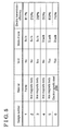
- the frequency of the alternating current power applied to the power supply coil 30 corresponds to 1.8 kilohertz, or kHz.
- the power transmission rate (output power divided by input power) corresponds to 81 percent, or 81 %.
- the core (a sample number 2) that is made of an iron bulk magnetic body and that does not include the void is used, the power transmission efficiency is reduced to 25 %.
- the power transmission efficiency is enhanced up to 38 % as shown in a sample number 3. Meanwhile, in a case where the cores that have the stacked iron magnetic bodies and that do not include the voids, respectively, the power transmission efficiency is enhanced up to 30 % as shown in a sample number 4. In a case where the cores that have the stacked iron magnetic bodies include the first and second voids 42, 62, respectively at predetermined positions, the power transmission efficiency is enhanced up to 69 % as shown in a sample number 5. As such, the power transmission efficiency may be enhanced by the first and second voids 42, 62 provided at the cores, and by the stack of the magnetic bodies of the cores.
- the power transmission efficiency is enhanced up to 76 % as shown in a sample number 6. This is similar to the known core shown in the sample number 1. As such, the contactless power supply device 1 may enhance the power transmission efficiency at low cost.
- the power supply core 40 is formed such that first annular core members 43 having U-shaped cross sections that are orthogonal to the circumferential direction are stacked with one another.
- the power receiving core 60 is formed such that second annular core members 63 having U-shaped cross sections that are orthogonal to the circumferential direction are stacked with one another.
- each of the power supply core 40 and the power receiving core 60 may be made from a bulk material.
- each of the first and second core members 43, 63 is made from an electromagnetic steel plate. Alternatively, other soft magnetic materials may be used.
- the disclosure may be used to a contactless power supply device that supplies power from a power unit to a power receiving unit without making the power supply unit and the power receiving unit come in contact with each other.
Applications Claiming Priority (1)
| Application Number | Priority Date | Filing Date | Title |
|---|---|---|---|
| JP2015188089A JP2017063567A (ja) | 2015-09-25 | 2015-09-25 | 無接点給電装置 |
Publications (1)
| Publication Number | Publication Date |
|---|---|
| EP3147917A1 true EP3147917A1 (en) | 2017-03-29 |
Family
ID=56990352
Family Applications (1)
| Application Number | Title | Priority Date | Filing Date |
|---|---|---|---|
| EP16190391.9A Withdrawn EP3147917A1 (en) | 2015-09-25 | 2016-09-23 | Contactless electric power supply device |
Country Status (3)
| Country | Link |
|---|---|
| US (1) | US20170093213A1 (ja) |
| EP (1) | EP3147917A1 (ja) |
| JP (1) | JP2017063567A (ja) |
Families Citing this family (2)
| Publication number | Priority date | Publication date | Assignee | Title |
|---|---|---|---|---|
| FR3084510B1 (fr) * | 2018-07-26 | 2020-11-27 | Valeo Systemes De Controle Moteur | Noyau magnetique pour former des bobines |
| US11223222B2 (en) * | 2019-09-13 | 2022-01-11 | Texas Institute Of Science, Inc. | Contactless charging apparatus and method for contactless charging |
Citations (4)
| Publication number | Priority date | Publication date | Assignee | Title |
|---|---|---|---|---|
| DE3802062A1 (de) * | 1987-01-26 | 1988-08-04 | Tokyo Keiki Kk | Magnetische induktionskopplungseinrichtung |
| US20080224543A1 (en) * | 2007-03-16 | 2008-09-18 | Fuji Xerox Co., Ltd. | Non-contact signal transmission apparatus |
| EP2631923A1 (en) * | 2012-02-23 | 2013-08-28 | Tyco Electronics Nederland B.V. | Wireless power connector and wireless power connector system |
| JP2013243250A (ja) | 2012-05-21 | 2013-12-05 | Kobe Steel Ltd | 非接触給電用コイル |
Family Cites Families (5)
| Publication number | Priority date | Publication date | Assignee | Title |
|---|---|---|---|---|
| US3260979A (en) * | 1963-12-11 | 1966-07-12 | Lionel E Leavitt | Through-wall electromagnetic coupling |
| US5216402A (en) * | 1992-01-22 | 1993-06-01 | Hughes Aircraft Company | Separable inductive coupler |
| US5808537A (en) * | 1996-09-16 | 1998-09-15 | Kabushiki Kaisha Toyoda Jidoshokki Seisakusho | Inductor core for transferring electric power to a conveyor carriage |
| EP1772940A3 (de) * | 2005-10-04 | 2011-05-18 | Prüftechnik Dieter Busch AG | Rotierübertrager zur Übertragung von elektrischer Energie oder Information |
| DE102015007586A1 (de) * | 2015-06-16 | 2016-12-22 | Audi Ag | Energieübertragungseinrichtung |
-
2015
- 2015-09-25 JP JP2015188089A patent/JP2017063567A/ja active Pending
-
2016
- 2016-09-23 US US15/274,013 patent/US20170093213A1/en not_active Abandoned
- 2016-09-23 EP EP16190391.9A patent/EP3147917A1/en not_active Withdrawn
Patent Citations (4)
| Publication number | Priority date | Publication date | Assignee | Title |
|---|---|---|---|---|
| DE3802062A1 (de) * | 1987-01-26 | 1988-08-04 | Tokyo Keiki Kk | Magnetische induktionskopplungseinrichtung |
| US20080224543A1 (en) * | 2007-03-16 | 2008-09-18 | Fuji Xerox Co., Ltd. | Non-contact signal transmission apparatus |
| EP2631923A1 (en) * | 2012-02-23 | 2013-08-28 | Tyco Electronics Nederland B.V. | Wireless power connector and wireless power connector system |
| JP2013243250A (ja) | 2012-05-21 | 2013-12-05 | Kobe Steel Ltd | 非接触給電用コイル |
Also Published As
| Publication number | Publication date |
|---|---|
| JP2017063567A (ja) | 2017-03-30 |
| US20170093213A1 (en) | 2017-03-30 |
Similar Documents
| Publication | Publication Date | Title |
|---|---|---|
| US10361025B2 (en) | Transformer and leakage transformer | |
| CN108028127B (zh) | 非接触供电用线圈及非接触供电系统 | |
| US8493167B2 (en) | Transformer having the heat radiation function | |
| JP6333525B2 (ja) | リニア電磁装置 | |
| JP4997330B2 (ja) | 多相変圧器および変圧システム | |
| KR20230004410A (ko) | 인덕티브 장치 | |
| JP2012099739A (ja) | コアセグメント、環状コイルコア及び環状コイル | |
| EP3147917A1 (en) | Contactless electric power supply device | |
| EP2787515B1 (en) | Inductor gap spacer | |
| WO2022131131A1 (ja) | 巻鉄心用誘導加熱式熱処理装置およびその熱処理方法 | |
| JP5668097B2 (ja) | 電線およびコイル | |
| US20160268037A1 (en) | Stationary Induction Electric Apparatus and Method for Making the Same | |
| JP2014179516A (ja) | トランス | |
| JP5918020B2 (ja) | 非接触給電用コイル | |
| KR101357259B1 (ko) | 태양광 발전용 전류센서 및 그 전류센서 제조방법 | |
| JP6060206B2 (ja) | 環状コイル | |
| JP6539024B2 (ja) | コイル、及びコイル部品 | |
| JP2016105464A (ja) | 磁気部品、および、電力伝送装置 | |
| JP2012156281A (ja) | 空芯コイル | |
| JP6308036B2 (ja) | リアクトル | |
| JP2017073486A (ja) | コイル部品 | |
| CN216487618U (zh) | 空心铁芯 | |
| KR101392045B1 (ko) | 고전압용 트랜스포머 구조체 | |
| CN113299466A (zh) | 空心铁芯 | |
| JP6604250B2 (ja) | ワイヤレス電力伝送用コイル、ワイヤレス給電システム、ワイヤレス受電システムおよびワイヤレス電力伝送システム |
Legal Events
| Date | Code | Title | Description |
|---|---|---|---|
| PUAI | Public reference made under article 153(3) epc to a published international application that has entered the european phase |
Free format text: ORIGINAL CODE: 0009012 |
|
| AK | Designated contracting states |
Kind code of ref document: A1 Designated state(s): AL AT BE BG CH CY CZ DE DK EE ES FI FR GB GR HR HU IE IS IT LI LT LU LV MC MK MT NL NO PL PT RO RS SE SI SK SM TR |
|
| AX | Request for extension of the european patent |
Extension state: BA ME |
|
| 17P | Request for examination filed |
Effective date: 20170925 |
|
| RBV | Designated contracting states (corrected) |
Designated state(s): AL AT BE BG CH CY CZ DE DK EE ES FI FR GB GR HR HU IE IS IT LI LT LU LV MC MK MT NL NO PL PT RO RS SE SI SK SM TR |
|
| STAA | Information on the status of an ep patent application or granted ep patent |
Free format text: STATUS: THE APPLICATION HAS BEEN WITHDRAWN |
|
| 18W | Application withdrawn |
Effective date: 20180619 |