EP3147575A1 - Procede et dispositif destines a la determination des besoins calorifiques d'un batiment - Google Patents
Procede et dispositif destines a la determination des besoins calorifiques d'un batiment Download PDFInfo
- Publication number
- EP3147575A1 EP3147575A1 EP16185415.3A EP16185415A EP3147575A1 EP 3147575 A1 EP3147575 A1 EP 3147575A1 EP 16185415 A EP16185415 A EP 16185415A EP 3147575 A1 EP3147575 A1 EP 3147575A1
- Authority
- EP
- European Patent Office
- Prior art keywords
- heat
- inf
- heat loss
- loss coefficient
- building
- Prior art date
- Legal status (The legal status is an assumption and is not a legal conclusion. Google has not performed a legal analysis and makes no representation as to the accuracy of the status listed.)
- Granted
Links
- 238000000034 method Methods 0.000 title claims abstract description 42
- 238000010438 heat treatment Methods 0.000 title claims description 45
- 238000009423 ventilation Methods 0.000 claims abstract description 51
- 230000005540 biological transmission Effects 0.000 claims abstract description 45
- 238000012546 transfer Methods 0.000 claims abstract description 31
- 238000005259 measurement Methods 0.000 claims description 16
- 238000001514 detection method Methods 0.000 claims description 9
- 238000012545 processing Methods 0.000 claims description 4
- 230000008569 process Effects 0.000 claims description 3
- 230000001419 dependent effect Effects 0.000 description 13
- 238000004364 calculation method Methods 0.000 description 8
- 239000002689 soil Substances 0.000 description 8
- 230000008859 change Effects 0.000 description 6
- 239000000779 smoke Substances 0.000 description 6
- 238000010276 construction Methods 0.000 description 5
- 238000011156 evaluation Methods 0.000 description 5
- 230000036961 partial effect Effects 0.000 description 5
- 239000004566 building material Substances 0.000 description 3
- 238000005265 energy consumption Methods 0.000 description 3
- 230000020169 heat generation Effects 0.000 description 3
- 230000036962 time dependent Effects 0.000 description 3
- XLYOFNOQVPJJNP-UHFFFAOYSA-N water Substances O XLYOFNOQVPJJNP-UHFFFAOYSA-N 0.000 description 3
- 238000004458 analytical method Methods 0.000 description 2
- 238000009795 derivation Methods 0.000 description 2
- 239000000446 fuel Substances 0.000 description 2
- 238000009413 insulation Methods 0.000 description 2
- 239000000463 material Substances 0.000 description 2
- 238000012544 monitoring process Methods 0.000 description 2
- 238000000926 separation method Methods 0.000 description 2
- 238000012935 Averaging Methods 0.000 description 1
- 241001652065 Trigonopeltastes delta Species 0.000 description 1
- 238000007630 basic procedure Methods 0.000 description 1
- 230000015572 biosynthetic process Effects 0.000 description 1
- 230000000052 comparative effect Effects 0.000 description 1
- 230000003247 decreasing effect Effects 0.000 description 1
- 238000013461 design Methods 0.000 description 1
- 238000010586 diagram Methods 0.000 description 1
- 230000004069 differentiation Effects 0.000 description 1
- 238000005516 engineering process Methods 0.000 description 1
- 230000008595 infiltration Effects 0.000 description 1
- 238000001764 infiltration Methods 0.000 description 1
- 230000035699 permeability Effects 0.000 description 1
- 230000000704 physical effect Effects 0.000 description 1
- 238000002360 preparation method Methods 0.000 description 1
- 238000002834 transmittance Methods 0.000 description 1
Images

Classifications
-
- G—PHYSICS
- G01—MEASURING; TESTING
- G01K—MEASURING TEMPERATURE; MEASURING QUANTITY OF HEAT; THERMALLY-SENSITIVE ELEMENTS NOT OTHERWISE PROVIDED FOR
- G01K17/00—Measuring quantity of heat
- G01K17/06—Measuring quantity of heat conveyed by flowing media, e.g. in heating systems e.g. the quantity of heat in a transporting medium, delivered to or consumed in an expenditure device
-
- F—MECHANICAL ENGINEERING; LIGHTING; HEATING; WEAPONS; BLASTING
- F24—HEATING; RANGES; VENTILATING
- F24D—DOMESTIC- OR SPACE-HEATING SYSTEMS, e.g. CENTRAL HEATING SYSTEMS; DOMESTIC HOT-WATER SUPPLY SYSTEMS; ELEMENTS OR COMPONENTS THEREFOR
- F24D19/00—Details
- F24D19/10—Arrangement or mounting of control or safety devices
- F24D19/1006—Arrangement or mounting of control or safety devices for water heating systems
- F24D19/1009—Arrangement or mounting of control or safety devices for water heating systems for central heating
- F24D19/1048—Counting of energy consumption
-
- F—MECHANICAL ENGINEERING; LIGHTING; HEATING; WEAPONS; BLASTING
- F24—HEATING; RANGES; VENTILATING
- F24F—AIR-CONDITIONING; AIR-HUMIDIFICATION; VENTILATION; USE OF AIR CURRENTS FOR SCREENING
- F24F5/00—Air-conditioning systems or apparatus not covered by F24F1/00 or F24F3/00, e.g. using solar heat or combined with household units such as an oven or water heater
- F24F5/0046—Air-conditioning systems or apparatus not covered by F24F1/00 or F24F3/00, e.g. using solar heat or combined with household units such as an oven or water heater using natural energy, e.g. solar energy, energy from the ground
-
- G—PHYSICS
- G01—MEASURING; TESTING
- G01K—MEASURING TEMPERATURE; MEASURING QUANTITY OF HEAT; THERMALLY-SENSITIVE ELEMENTS NOT OTHERWISE PROVIDED FOR
- G01K17/00—Measuring quantity of heat
-
- G—PHYSICS
- G01—MEASURING; TESTING
- G01K—MEASURING TEMPERATURE; MEASURING QUANTITY OF HEAT; THERMALLY-SENSITIVE ELEMENTS NOT OTHERWISE PROVIDED FOR
- G01K17/00—Measuring quantity of heat
- G01K17/06—Measuring quantity of heat conveyed by flowing media, e.g. in heating systems e.g. the quantity of heat in a transporting medium, delivered to or consumed in an expenditure device
- G01K17/08—Measuring quantity of heat conveyed by flowing media, e.g. in heating systems e.g. the quantity of heat in a transporting medium, delivered to or consumed in an expenditure device based upon measurement of temperature difference or of a temperature
- G01K17/20—Measuring quantity of heat conveyed by flowing media, e.g. in heating systems e.g. the quantity of heat in a transporting medium, delivered to or consumed in an expenditure device based upon measurement of temperature difference or of a temperature across a radiating surface, combined with ascertainment of the heat transmission coefficient
-
- F—MECHANICAL ENGINEERING; LIGHTING; HEATING; WEAPONS; BLASTING
- F24—HEATING; RANGES; VENTILATING
- F24S—SOLAR HEAT COLLECTORS; SOLAR HEAT SYSTEMS
- F24S2201/00—Prediction; Simulation
-
- F—MECHANICAL ENGINEERING; LIGHTING; HEATING; WEAPONS; BLASTING
- F24—HEATING; RANGES; VENTILATING
- F24V—COLLECTION, PRODUCTION OR USE OF HEAT NOT OTHERWISE PROVIDED FOR
- F24V99/00—Subject matter not provided for in other main groups of this subclass
-
- F—MECHANICAL ENGINEERING; LIGHTING; HEATING; WEAPONS; BLASTING
- F28—HEAT EXCHANGE IN GENERAL
- F28F—DETAILS OF HEAT-EXCHANGE AND HEAT-TRANSFER APPARATUS, OF GENERAL APPLICATION
- F28F2200/00—Prediction; Simulation; Testing
-
- G—PHYSICS
- G06—COMPUTING; CALCULATING OR COUNTING
- G06F—ELECTRIC DIGITAL DATA PROCESSING
- G06F30/00—Computer-aided design [CAD]
- G06F30/10—Geometric CAD
- G06F30/13—Architectural design, e.g. computer-aided architectural design [CAAD] related to design of buildings, bridges, landscapes, production plants or roads
Definitions
- the invention relates to a method and a device for determining a building heat demand based on heat consumption data according to the preamble of claim 1. This can be done, for example, in the context of building classifications, for example, in the preparation of a building energy certificate based on the heat consumption data.
- a total heat loss coefficient is determined, preferably from the heat consumption data indicative of the amount of heat consumed by space heating. With the method described, it is possible to determine a mean building heat loss coefficient of a building, and thus also to determine the heat demand of the entire building.
- the building heat demand, u.a. is used as a design value for the space heating, is usually determined by a calculation method.
- the thermal conductivity and thickness of all enclosing components of the building, especially screed, walls, roof, must be known. In existing buildings, a subsequent determination is often not readily possible.
- the thermal conductivity values typical characteristics are used in such a case, the tables are taken and depend on the year of construction of the building. Building-specific ventilation losses, such as joint ventilation due to leaks, heat pressures and the like, are usually taken into account by means of lump sums.
- Another, currently practiced possibility is to determine the actual measured consumption of a building and use weather-adjusted as a total heat demand.
- the above-described calculation method has the disadvantage that even with a precise knowledge of the building materials used, the determined heat requirement remains a purely theoretical value, which does not take into account deviations in practice. These deviations can result from the fact that materials deviating from the planning were used in the construction of the building or losses occur due to improperly connected insulation layers and thus thermal bridges are created. If blanket thermal conductivity values are used in construction tables that consider commonly used materials at this time, the inaccuracy is even greater. Overall, there are a large number of influencing factors which - as the practice shows - sometimes result in significant deviations from the only theoretically calculated building heat demand.
- the methods used to date for determining the building heat demand from consumption values are also inadequate because user behavior has a very large influence on the actual energy consumption of a building and so far has been taken insufficiently into account.
- the ventilation behavior and individually desired room temperatures should be mentioned here.
- one and the same building can have very different consumption values with different user structures.
- the consumption of an entire heating period is usually considered. Within this period, however, the building is exposed to a variety of internal and external influences, which are typically not taken into account.
- the object of the invention is to determine a more reliable value for the building heat requirement using heat consumption data, without the building materials used must be known exactly and weak points of the building must be determined in advance.
- the transmission heat coefficient essentially takes into account the heat permeability of the building shell due to heat conduction and is therefore a measure of the thermal quality of the heat-conducting building shell.
- the ventilation heat loss coefficient takes into account time-dependent ventilation losses, which include the time-dependent ventilation behavior of the users as well as a time-varying wind load or other time-variant infiltration-related disturbance variables.
- the transmission heat transfer coefficient is largely independent of the user behavior and thus time invariant.
- the temporally substantially invariant transmission heat transfer coefficient and the time-variant ventilation heat loss coefficient With the temporally substantially invariant transmission heat transfer coefficient and the time-variant ventilation heat loss coefficient, the heat demand of a building for different outdoor and indoor temperatures can be easily determined and vulnerabilities in the building envelope and special features in the ventilation behavior of the user can be detected.
- the transmission heat transfer coefficient separately for rooms with (especially exclusively) outside air contact (ie in particular rooms without ground contact) and for rooms with at least partial ground contact, since the heat losses and the outdoor temperature dependence are different in these rooms. Even internal rooms can be attributed in particular the rooms with only outside air contact, if they have no ground contact.
- the total heat loss coefficient mathematically from the derivation of the amount of heat used for the space heating, in particular per measuring interval according to the outside temperature.
- the total heat loss coefficient can be calculated from the ratio of the time derivative of the amount of heat used for the space heating per measurement interval and the time derivative of the outside temperature is determined. The required measured quantities can be easily captured, as can be seen from the formulas disclosed below for the calculation.
- a total heat loss coefficient is determined starting from a building heat loss measured or determined in particular on the basis of the heat consumption data. Subsequently, the transmission heat transfer coefficient is calculated using the total heat loss coefficient and a (for example, also estimated) minimum ventilation heat coefficient. From the total heat loss coefficient and the transmission heat transfer coefficient, the ventilation heat loss coefficient, which is dependent on the user behavior and weather influences, and therefore time-variant, is subsequently calculated. The transmission heat transfer coefficient is divided into an outside-temperature-independent and outside-temperature-dependent one Part. Depending on the type of consumption data, different calculation or determination methods are available for this purpose, which will be discussed in detail later. All of these methods form a particularly preferred embodiment of the present invention.
- both central measuring devices in particular heat meters, as well as decentralized measuring devices, such as heat cost allocators or even smoke detectors, come into question for the detection of the heat consumption and temperature data.
- the measuring devices optionally allow the detection of the transported into the respective building parts amount of heat, ie a separate detection for internal rooms and rooms exclusively with outside air contact or at least partial ground contact.
- the aforementioned central detection of the amount of heat emitted can also be combined with a decentralized detection, in which the heat consumption data by decentralized measuring devices, in particular mounted on the radiators heat cost allocators, the heat released for heating amount of heat are detected.
- the measuring devices detect the amount of heat or the heat consumption of individual radiators, heating strands, building parts and / or rooms, which in their sum yield the heat released in the entire building.
- heat meter can be used, which detect individual heating strands or rooms.
- the decentralized, possibly also the central, measuring systems are preferably equipped with radio transmission devices in order to transmit their measured values to data collecting points (data collectors), for example in the context of existing reading systems for recording heating costs with electronic heat cost allocators.
- data collectors data collecting points
- the system can also be implemented with wired systems.
- the decentralized measuring devices can also be used completely instead of the central measuring devices.
- measurement data are selected only from largely stationary system states in order to determine the time-invariant transmission heat transfer coefficient and the time-variant ventilation heat loss coefficient.
- this phase of steady-state system conditions can be monitored by monitoring room interior temperatures and their gradients over time, i. whose time derivative is identified. If the room interior temperatures do not change or only slightly change with time in a predetermined period of time, a stationary state in the considered building or building part can be assumed, so that in particular the transmission heat transfer coefficient and the ventilation heat loss coefficient can be reliably determined. This is also important because an averaging over time is made for their determination and changes in the measured variables in a non-stationary period would distort the results.
- the invention further relates to a device for determining a building heat demand, in particular in the context of building classifications, for example, in the creation of a building energy certificate based on a total heat loss coefficient, which is preferably determined from the heat used by the space heating amount of heat consumption data.
- the device is equipped with a central detection and processing unit, which has interfaces for connecting measuring devices for determining the heat consumption and a computing unit.
- the arithmetic unit is configured to receive, store and further process the measured data acquired by the measuring devices by determining a total heat loss coefficient.
- the total heat loss coefficient is divided into a time-invariant transmission heat transfer coefficient with an external temperature-dependent and an outdoor temperature-independent part and a time-variant ventilation heat loss coefficient with the arithmetic unit set up for this purpose.
- the arithmetic unit is set up by programming in particular for carrying out the previously described method or individual method steps and can therefore be used particularly well for carrying out the method described above.
- heat meters, heat cost allocators and / or temperature sensors are connected to the interfaces as measuring devices.
- the temperature sensors are intended to measure internal room temperatures, the outside temperature and / or the ground or floor temperature.
- the temperature sensors can be part of heat cost allocators or smoke detectors.
- the inventively proposed determination of the parameters "transmission heat transfer coefficient” and “ventilation heat loss coefficient” characterizing the heat loss characteristic values are determined, which allow a comparative assessment of the energy quality of the building envelope of different buildings in a reliable manner due to consumption data.
- One of the parameters namely the transmission heat transfer coefficient, hides the user behavior as far as possible. It is possible to determine this energetic building characteristic value without knowledge of the wall construction, the building materials used and possible deviations in the execution of a construction plan.
- the second characteristic ventilation heat loss coefficient then takes into account the time-variant influences, which are typically dominated by the user behavior and weather conditions.
- the arithmetic unit of the device is adapted to carry out the method described above or parts thereof.
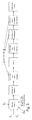
- FIG. 1 schematically shows a building with the rooms Z6, Z7, Z8 having basement, which is located in the ground, a ground floor with the rooms Z1, Z10, Z5, with a first floor with the rooms Z2, Z9, Z4 and a roof with the room Z3.
- the rooms of the ground floor, the first Stocks and the roof have apart from the internal spaces Z9 and Z10 each have an outer surface to the outside air.
- the cellar has an outer surface to the ground.
- the outdoor area also referred to as the building envelope
- the outdoor area is dotted for outdoor use to outside air and dashed for outdoor use to the ground.
- the relevant for the implementation of the proposed method according to the invention transmission currents which lead to transmission losses through the building exterior shell are represented by bold arrows, each associated with a transmission loss Q ⁇ this room.
- the transmission currents between individual rooms and thus also the total transmission currents from internal rooms need not be considered, since these are automatically included in the transmission losses through the building envelope.
- the external temperature ⁇ A which is determined by a central outside temperature sensor and used by the heating system or by another measuring and control system, enters the proposed method as a further measured variable.
- the amounts of heat that are used to determine the building heat loss Q ⁇ are proportional to the temperatures of the individual rooms ⁇ i , which are measured by Schumacherer conductedssysteme or smoke detectors or by means of separate temperature sensors, and the difference between indoor and outdoor or indoor and Erdreichtemperatur ,
- FIG. 2 is the system for measured value acquisition and implementation of the method shown schematically.
- the internal temperatures ⁇ i are measured, which is a measure of the amount of heat consumed in this room.
- These temperatures ⁇ i can be temperatures detected in particular by heat cost allocators or smoke alarms or else by means of separate temperature sensors.
- the outside temperature ⁇ a possibly also the ground temperature ⁇ basic (in FIG. 2 not shown) and the flow temperature of the heating system ⁇ flow (which can be used to determine the amount of heat consumed on individual radiators) detected by a central detection and processing device and stored there for further processing.
- the ventilation and transmission loss component can be estimated with the aid of the detected heat quantities by observations and evaluation over a relatively long period of time, and the resulting transmission heat and ventilation heat loss coefficients can be determined.
- the measured data shown are automatically collected, for example by wire or radio, and can be located exactly in time. This makes it possible to choose a relatively short observation period. Repeated measurement cycles at different times of the day and comparisons allow external influences and user behavior to be identified and eliminated in the evaluation of the data.
- FIG. 3 illustrates the sequence of the method according to the invention in a variant of the method.
- Q ⁇ inf c air * ⁇ air * H ⁇ NE * ⁇ LW * ⁇ R a ⁇ ume A N .
- AV mean temperature difference between inside and outside air temperature of the rooms [K];
- c air ⁇ air ⁇ physical properties of air: specific heat capacity and density;
- h ⁇ NE ... average storey height of the ventilated rooms of the building [m];
- R a ⁇ ume usable area of the considered rooms or building parts [m 2 ];
- the average area-related temperature differences required in the above equations can be determined as follows.
- the outside temperature-dependent heat loss thus results as a quantity that depends on the time-invariant transmission heat transfer coefficient u trans, AL and the time-variant ventilation heat loss coefficient u inf .
- the total heat loss coefficient u A from the derivation of the amount of heat used for the space heating according to the outside temperature can be determined by calculation in a manner.
- the total heat loss coefficient according to the invention can also be determined computationally and / or graphically in the following two ways.
- the partial derivatives according to the outside temperature can also be determined: ⁇ ⁇ ⁇ A Q ⁇ ⁇ loss ⁇ ⁇ ⁇ t ⁇ Q RH ⁇ t ⁇ ⁇ t ⁇ ⁇ A
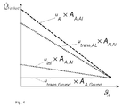
- ⁇ ⁇ A Q ⁇ ⁇ loss is the amount of negative increase in Fig. 4 linearized characteristic Q ⁇ ⁇ loss over ⁇ A.
- the partial derivatives from the values determined over the measurement interval ⁇ t can be determined by means of ratio formation of the changes in the values: ⁇ ⁇ ⁇ A Q ⁇ ⁇ loss ⁇ ⁇ ⁇ Q RH ⁇ t ⁇ ⁇ ⁇ A
- the transmission heat transfer coefficient u t ral1s, AL is approximately constant, ie time-invariant, and the ventilation heat loss coefficient u inf must be time-varying both because of time-dependent ventilation behavior of the user as well as time-variant wind load and resulting time-variant mean air exchange ⁇ LW in the building, is exploited according to the invention that the transmission heat transfer coefficient u t ral1s, AL must be independent of the outside temperature and thus practically equal for all measured values and measuring periods.
- the transmission heat transfer coefficient and the ventilation heat loss coefficient are computationally determined based on a space heater
- the theoretical transmission heat transmittance coefficient ⁇ trans, AL depending on the heat conduction of the building envelope can be determined sufficiently accurately from consumption data since time variant influences as user behavior and wind load according to the invention are mapped in the time-variant ventilation heat loss coefficient u inf , which also allows conclusions about the user behavior and in an energetically nonsensical behavior appropriate references to the user allows that can be automatically generated by comparison with meaningful user profiles.
- the transmission heat transfer coefficient u trans, AL and the ventilation heat loss coefficient u inf can also be determined graphically. This will be explained below with reference to Fig. 4 explained.
- the steepness of the point cloud Q ⁇ ⁇ RH ⁇ ⁇ A for example, determined by regression characteristic Q ⁇ RH ⁇ A the mean heating performance decreasing with increasing outside temperature (determined, for example, per hour) corresponds to the product of building parts ( A A, AL ) that touch the outside air and the desired negative, external temperature-dependent total heat loss coefficient - u A * A A, AL .
- decentralized measuring devices which record the amounts of heat or heat consumption of the heating strands (pipe heat), the parts of the building (due to user separation) or the rooms or apartments and record in their sum the entire building.
- the average internal building temperature is first determined by the individual temperatures of all rooms of the building are recorded. To detect the room temperatures, a measuring device is used in each room. In this case, reference should be made to an already existing measuring device, for example electronic heat cost allocators, which detect the room temperature with a sensor, temperature sensors of an electronic individual room control system or temperature sensors of other devices (eg smoke detectors).
- electronic heat cost allocators which detect the room temperature with a sensor, temperature sensors of an electronic individual room control system or temperature sensors of other devices (eg smoke detectors).
- thermometer electronic thermometer
- the recorded measured values merely have to be suitably selected and evaluated. This can be done by a program technically configured according arithmetic unit.
- the indices AL, IL, Reason used in the above quantities mean that the respective quantities refer to rooms with outside air contact (AL), to interior rooms (IL) or to rooms with ground contact (ground).
Landscapes
- Engineering & Computer Science (AREA)
- Chemical & Material Sciences (AREA)
- Combustion & Propulsion (AREA)
- Physics & Mathematics (AREA)
- General Physics & Mathematics (AREA)
- Mechanical Engineering (AREA)
- General Engineering & Computer Science (AREA)
- Life Sciences & Earth Sciences (AREA)
- Thermal Sciences (AREA)
- Sustainable Energy (AREA)
- Sustainable Development (AREA)
- Air Conditioning Control Device (AREA)
Applications Claiming Priority (1)
| Application Number | Priority Date | Filing Date | Title |
|---|---|---|---|
| DE102015116001.3A DE102015116001B3 (de) | 2015-09-22 | 2015-09-22 | Verfahren und Vorrichtung zur Bestimmung eines Gebäudewärmebedarfs |
Publications (2)
| Publication Number | Publication Date |
|---|---|
| EP3147575A1 true EP3147575A1 (fr) | 2017-03-29 |
| EP3147575B1 EP3147575B1 (fr) | 2019-08-07 |
Family
ID=56855271
Family Applications (1)
| Application Number | Title | Priority Date | Filing Date |
|---|---|---|---|
| EP16185415.3A Active EP3147575B1 (fr) | 2015-09-22 | 2016-08-24 | Procede et dispositif destines a la determination des besoins calorifiques d'un batiment |
Country Status (2)
| Country | Link |
|---|---|
| EP (1) | EP3147575B1 (fr) |
| DE (1) | DE102015116001B3 (fr) |
Cited By (1)
| Publication number | Priority date | Publication date | Assignee | Title |
|---|---|---|---|---|
| CN112984615A (zh) * | 2021-03-05 | 2021-06-18 | 京源中科科技股份有限公司 | 一种基于物联网的热计量分摊系统及方法 |
Citations (6)
| Publication number | Priority date | Publication date | Assignee | Title |
|---|---|---|---|---|
| DE3012267A1 (de) * | 1980-03-29 | 1981-10-08 | I.B.L. Ingenieurbüro Lienenkämper, 4005 Meerbusch | Verfahren und vorrichtung zur messung und auswertung des waermemengenverbrauchs von abnehmern in beheizten gebaeuden |
| WO1998008179A1 (fr) * | 1996-08-22 | 1998-02-26 | Emv Technologies, Inc. | Systeme et procede de mesure et de controle de l'energie avec reference de la ligne de base constante |
| DE10057834A1 (de) * | 2000-11-22 | 2002-06-06 | Ingo Brauns | Verfahren zur Kontrolle des Energieverbrauchs einer Heiz- und/oder Kühlanlage |
| DE10062581A1 (de) * | 2000-12-15 | 2002-07-04 | Deutsch Zentr Luft & Raumfahrt | Verfahren und Vorrichtung zur Ermittlung des Nennwärmebedarfs eines Heizungssystems |
| US20070235550A1 (en) * | 2004-02-20 | 2007-10-11 | Martin Donath | Determination of the Connected Heating Load of a Building |
| US20100012740A1 (en) * | 2008-07-16 | 2010-01-21 | Commissariat A L'energie Atomique | Aid for loading a solid fuel boiler coupled with an accumulation system |
-
2015
- 2015-09-22 DE DE102015116001.3A patent/DE102015116001B3/de not_active Expired - Fee Related
-
2016
- 2016-08-24 EP EP16185415.3A patent/EP3147575B1/fr active Active
Patent Citations (6)
| Publication number | Priority date | Publication date | Assignee | Title |
|---|---|---|---|---|
| DE3012267A1 (de) * | 1980-03-29 | 1981-10-08 | I.B.L. Ingenieurbüro Lienenkämper, 4005 Meerbusch | Verfahren und vorrichtung zur messung und auswertung des waermemengenverbrauchs von abnehmern in beheizten gebaeuden |
| WO1998008179A1 (fr) * | 1996-08-22 | 1998-02-26 | Emv Technologies, Inc. | Systeme et procede de mesure et de controle de l'energie avec reference de la ligne de base constante |
| DE10057834A1 (de) * | 2000-11-22 | 2002-06-06 | Ingo Brauns | Verfahren zur Kontrolle des Energieverbrauchs einer Heiz- und/oder Kühlanlage |
| DE10062581A1 (de) * | 2000-12-15 | 2002-07-04 | Deutsch Zentr Luft & Raumfahrt | Verfahren und Vorrichtung zur Ermittlung des Nennwärmebedarfs eines Heizungssystems |
| US20070235550A1 (en) * | 2004-02-20 | 2007-10-11 | Martin Donath | Determination of the Connected Heating Load of a Building |
| US20100012740A1 (en) * | 2008-07-16 | 2010-01-21 | Commissariat A L'energie Atomique | Aid for loading a solid fuel boiler coupled with an accumulation system |
Cited By (1)
| Publication number | Priority date | Publication date | Assignee | Title |
|---|---|---|---|---|
| CN112984615A (zh) * | 2021-03-05 | 2021-06-18 | 京源中科科技股份有限公司 | 一种基于物联网的热计量分摊系统及方法 |
Also Published As
| Publication number | Publication date |
|---|---|
| DE102015116001B3 (de) | 2016-12-15 |
| EP3147575B1 (fr) | 2019-08-07 |
Similar Documents
| Publication | Publication Date | Title |
|---|---|---|
| EP2691756B1 (fr) | Détection de fuites par bilan massique stochastique | |
| EP1730482B1 (fr) | Déterminer la charge thermique d'un bâtiment | |
| EP1933220B1 (fr) | Procédé de détermination de l'état d'alimentation d'un circuit de chauffage ou d'un bâtiment et régulateur d'état d'alimentation | |
| EP1936290B1 (fr) | Procédé et dispositif destinés à la détection de l'état hydraulique d'une installation de chauffage | |
| EP2966534B1 (fr) | Procédé de détermination du besoin thermique de bâtiments résidentiels | |
| EP3147575B1 (fr) | Procede et dispositif destines a la determination des besoins calorifiques d'un batiment | |
| EP1592948B1 (fr) | Procede pour parametrer un repartiteur de frais de chauffage | |
| DE10030294B4 (de) | Verfahren zur Erfassung des Energieverbrauches und der Sanierungsbedürftigkeit eines Gebäudes | |
| EP3599583A1 (fr) | Détermination de la consommation de l'énergie de chauffage ou de refroidissement d'une sous-unité de construction | |
| DE112016002589T5 (de) | Verfahren zur Detektion einer offenen Lüftungsöffnung | |
| DE3529257A1 (de) | Verfahren und anordnung zur ermittlung der waermeabgabe von heizflaechen einer heizungsanlage | |
| EP3602146B1 (fr) | Procédé et dispositif pour la détermination de la probabilité de dommages dus à la moisissure et/ou l'humidité dans un bâtiment | |
| EP3635492A1 (fr) | Procédé de fonctionnement d'un système de consommation thermique | |
| DE102008061087B4 (de) | Verfahren und Vorrichtungsanordnung zur Erfassung und Auswertung von Raumklimadaten | |
| EP2327971B1 (fr) | Procédé d'analyse de la répartition des quantités de chaleur dans un système de chauffage et dispositif d'exécution du procédé | |
| EP2677374B1 (fr) | Procédé de surveillance d'une installation de chauffage | |
| EP3336500B1 (fr) | Appareil électronique et procédé de distribution de quantité de chaud et froid par l'intermédiaire de surfaces chauffantes standards | |
| DE19756104C5 (de) | Verfahren zur Regelung der Vorlauftemperatur einer Zentralheizungsanlage bzw. eines Heizkreises | |
| EP3035144B1 (fr) | Procédé et dispositif pour contrôler la décharge d'énergie thermique dans des structures résidentielles locales et régionales | |
| EP2392867A2 (fr) | Système d'information basé sur un système de chauffage avec des pompes d'alimentation locale, et procédé d'utilisation du système d'information | |
| DE102016111280A1 (de) | Verfahren zur Ermittlung des Jahresnutzungsgrads einer wärmetechnischen Anlage | |
| DE102019007474A1 (de) | Verfahren und Vorrichtung zur Überwachung einer Dampfbremse oder Dampfsperre einer Gebäudehülle | |
| EP3009908B1 (fr) | Procédé et agencement de dispositif destinés à enregistrer, évaluer et influencer la répartition de la distribution des énergies de chauffage au sein d'une enveloppe de bâtiment | |
| EP3529542B1 (fr) | Procédé pour calculer des températures d'un réservoir souterrain pour le fonctionnement d'une installation géothermique | |
| DE102021203000B4 (de) | Verfahren zum Betrieb einer Heizkostenverteilervorrichtung und Heizkostenverteilervorrichtung |
Legal Events
| Date | Code | Title | Description |
|---|---|---|---|
| PUAI | Public reference made under article 153(3) epc to a published international application that has entered the european phase |
Free format text: ORIGINAL CODE: 0009012 |
|
| STAA | Information on the status of an ep patent application or granted ep patent |
Free format text: STATUS: THE APPLICATION HAS BEEN PUBLISHED |
|
| AK | Designated contracting states |
Kind code of ref document: A1 Designated state(s): AL AT BE BG CH CY CZ DE DK EE ES FI FR GB GR HR HU IE IS IT LI LT LU LV MC MK MT NL NO PL PT RO RS SE SI SK SM TR |
|
| AX | Request for extension of the european patent |
Extension state: BA ME |
|
| STAA | Information on the status of an ep patent application or granted ep patent |
Free format text: STATUS: REQUEST FOR EXAMINATION WAS MADE |
|
| 17P | Request for examination filed |
Effective date: 20170927 |
|
| RBV | Designated contracting states (corrected) |
Designated state(s): AL AT BE BG CH CY CZ DE DK EE ES FI FR GB GR HR HU IE IS IT LI LT LU LV MC MK MT NL NO PL PT RO RS SE SI SK SM TR |
|
| REG | Reference to a national code |
Ref country code: DE Ref legal event code: R079 Ref document number: 502016005899 Country of ref document: DE Free format text: PREVIOUS MAIN CLASS: F24D0005000000 Ipc: F24D0019100000 |
|
| GRAP | Despatch of communication of intention to grant a patent |
Free format text: ORIGINAL CODE: EPIDOSNIGR1 |
|
| STAA | Information on the status of an ep patent application or granted ep patent |
Free format text: STATUS: GRANT OF PATENT IS INTENDED |
|
| RIC1 | Information provided on ipc code assigned before grant |
Ipc: G01K 17/06 20060101ALI20190213BHEP Ipc: F24F 5/00 20060101ALI20190213BHEP Ipc: G06F 17/50 20060101ALI20190213BHEP Ipc: F24D 19/10 20060101AFI20190213BHEP Ipc: G01K 17/00 20060101ALI20190213BHEP |
|
| INTG | Intention to grant announced |
Effective date: 20190313 |
|
| GRAS | Grant fee paid |
Free format text: ORIGINAL CODE: EPIDOSNIGR3 |
|
| GRAA | (expected) grant |
Free format text: ORIGINAL CODE: 0009210 |
|
| STAA | Information on the status of an ep patent application or granted ep patent |
Free format text: STATUS: THE PATENT HAS BEEN GRANTED |
|
| AK | Designated contracting states |
Kind code of ref document: B1 Designated state(s): AL AT BE BG CH CY CZ DE DK EE ES FI FR GB GR HR HU IE IS IT LI LT LU LV MC MK MT NL NO PL PT RO RS SE SI SK SM TR |
|
| REG | Reference to a national code |
Ref country code: GB Ref legal event code: FG4D Free format text: NOT ENGLISH |
|
| REG | Reference to a national code |
Ref country code: CH Ref legal event code: EP Ref country code: AT Ref legal event code: REF Ref document number: 1164463 Country of ref document: AT Kind code of ref document: T Effective date: 20190815 |
|
| REG | Reference to a national code |
Ref country code: DE Ref legal event code: R096 Ref document number: 502016005899 Country of ref document: DE |
|
| REG | Reference to a national code |
Ref country code: IE Ref legal event code: FG4D Free format text: LANGUAGE OF EP DOCUMENT: GERMAN |
|
| REG | Reference to a national code |
Ref country code: CH Ref legal event code: NV Representative=s name: BOHEST AG, CH |
|
| REG | Reference to a national code |
Ref country code: NL Ref legal event code: MP Effective date: 20190807 |
|
| REG | Reference to a national code |
Ref country code: LT Ref legal event code: MG4D |
|
| PG25 | Lapsed in a contracting state [announced via postgrant information from national office to epo] |
Ref country code: PT Free format text: LAPSE BECAUSE OF FAILURE TO SUBMIT A TRANSLATION OF THE DESCRIPTION OR TO PAY THE FEE WITHIN THE PRESCRIBED TIME-LIMIT Effective date: 20191209 Ref country code: NO Free format text: LAPSE BECAUSE OF FAILURE TO SUBMIT A TRANSLATION OF THE DESCRIPTION OR TO PAY THE FEE WITHIN THE PRESCRIBED TIME-LIMIT Effective date: 20191107 Ref country code: BG Free format text: LAPSE BECAUSE OF FAILURE TO SUBMIT A TRANSLATION OF THE DESCRIPTION OR TO PAY THE FEE WITHIN THE PRESCRIBED TIME-LIMIT Effective date: 20191107 Ref country code: SE Free format text: LAPSE BECAUSE OF FAILURE TO SUBMIT A TRANSLATION OF THE DESCRIPTION OR TO PAY THE FEE WITHIN THE PRESCRIBED TIME-LIMIT Effective date: 20190807 Ref country code: HR Free format text: LAPSE BECAUSE OF FAILURE TO SUBMIT A TRANSLATION OF THE DESCRIPTION OR TO PAY THE FEE WITHIN THE PRESCRIBED TIME-LIMIT Effective date: 20190807 Ref country code: NL Free format text: LAPSE BECAUSE OF FAILURE TO SUBMIT A TRANSLATION OF THE DESCRIPTION OR TO PAY THE FEE WITHIN THE PRESCRIBED TIME-LIMIT Effective date: 20190807 Ref country code: LT Free format text: LAPSE BECAUSE OF FAILURE TO SUBMIT A TRANSLATION OF THE DESCRIPTION OR TO PAY THE FEE WITHIN THE PRESCRIBED TIME-LIMIT Effective date: 20190807 Ref country code: FI Free format text: LAPSE BECAUSE OF FAILURE TO SUBMIT A TRANSLATION OF THE DESCRIPTION OR TO PAY THE FEE WITHIN THE PRESCRIBED TIME-LIMIT Effective date: 20190807 |
|
| PG25 | Lapsed in a contracting state [announced via postgrant information from national office to epo] |
Ref country code: ES Free format text: LAPSE BECAUSE OF FAILURE TO SUBMIT A TRANSLATION OF THE DESCRIPTION OR TO PAY THE FEE WITHIN THE PRESCRIBED TIME-LIMIT Effective date: 20190807 Ref country code: AL Free format text: LAPSE BECAUSE OF FAILURE TO SUBMIT A TRANSLATION OF THE DESCRIPTION OR TO PAY THE FEE WITHIN THE PRESCRIBED TIME-LIMIT Effective date: 20190807 Ref country code: GR Free format text: LAPSE BECAUSE OF FAILURE TO SUBMIT A TRANSLATION OF THE DESCRIPTION OR TO PAY THE FEE WITHIN THE PRESCRIBED TIME-LIMIT Effective date: 20191108 Ref country code: IS Free format text: LAPSE BECAUSE OF FAILURE TO SUBMIT A TRANSLATION OF THE DESCRIPTION OR TO PAY THE FEE WITHIN THE PRESCRIBED TIME-LIMIT Effective date: 20191207 Ref country code: RS Free format text: LAPSE BECAUSE OF FAILURE TO SUBMIT A TRANSLATION OF THE DESCRIPTION OR TO PAY THE FEE WITHIN THE PRESCRIBED TIME-LIMIT Effective date: 20190807 Ref country code: LV Free format text: LAPSE BECAUSE OF FAILURE TO SUBMIT A TRANSLATION OF THE DESCRIPTION OR TO PAY THE FEE WITHIN THE PRESCRIBED TIME-LIMIT Effective date: 20190807 |
|
| PG25 | Lapsed in a contracting state [announced via postgrant information from national office to epo] |
Ref country code: TR Free format text: LAPSE BECAUSE OF FAILURE TO SUBMIT A TRANSLATION OF THE DESCRIPTION OR TO PAY THE FEE WITHIN THE PRESCRIBED TIME-LIMIT Effective date: 20190807 |
|
| PG25 | Lapsed in a contracting state [announced via postgrant information from national office to epo] |
Ref country code: RO Free format text: LAPSE BECAUSE OF FAILURE TO SUBMIT A TRANSLATION OF THE DESCRIPTION OR TO PAY THE FEE WITHIN THE PRESCRIBED TIME-LIMIT Effective date: 20190807 Ref country code: DK Free format text: LAPSE BECAUSE OF FAILURE TO SUBMIT A TRANSLATION OF THE DESCRIPTION OR TO PAY THE FEE WITHIN THE PRESCRIBED TIME-LIMIT Effective date: 20190807 Ref country code: EE Free format text: LAPSE BECAUSE OF FAILURE TO SUBMIT A TRANSLATION OF THE DESCRIPTION OR TO PAY THE FEE WITHIN THE PRESCRIBED TIME-LIMIT Effective date: 20190807 Ref country code: PL Free format text: LAPSE BECAUSE OF FAILURE TO SUBMIT A TRANSLATION OF THE DESCRIPTION OR TO PAY THE FEE WITHIN THE PRESCRIBED TIME-LIMIT Effective date: 20190807 |
|
| PG25 | Lapsed in a contracting state [announced via postgrant information from national office to epo] |
Ref country code: LU Free format text: LAPSE BECAUSE OF NON-PAYMENT OF DUE FEES Effective date: 20190824 Ref country code: SK Free format text: LAPSE BECAUSE OF FAILURE TO SUBMIT A TRANSLATION OF THE DESCRIPTION OR TO PAY THE FEE WITHIN THE PRESCRIBED TIME-LIMIT Effective date: 20190807 Ref country code: MC Free format text: LAPSE BECAUSE OF FAILURE TO SUBMIT A TRANSLATION OF THE DESCRIPTION OR TO PAY THE FEE WITHIN THE PRESCRIBED TIME-LIMIT Effective date: 20190807 Ref country code: SM Free format text: LAPSE BECAUSE OF FAILURE TO SUBMIT A TRANSLATION OF THE DESCRIPTION OR TO PAY THE FEE WITHIN THE PRESCRIBED TIME-LIMIT Effective date: 20190807 Ref country code: CZ Free format text: LAPSE BECAUSE OF FAILURE TO SUBMIT A TRANSLATION OF THE DESCRIPTION OR TO PAY THE FEE WITHIN THE PRESCRIBED TIME-LIMIT Effective date: 20190807 Ref country code: IS Free format text: LAPSE BECAUSE OF FAILURE TO SUBMIT A TRANSLATION OF THE DESCRIPTION OR TO PAY THE FEE WITHIN THE PRESCRIBED TIME-LIMIT Effective date: 20200224 |
|
| REG | Reference to a national code |
Ref country code: BE Ref legal event code: MM Effective date: 20190831 |
|
| REG | Reference to a national code |
Ref country code: DE Ref legal event code: R097 Ref document number: 502016005899 Country of ref document: DE |
|
| PLBE | No opposition filed within time limit |
Free format text: ORIGINAL CODE: 0009261 |
|
| STAA | Information on the status of an ep patent application or granted ep patent |
Free format text: STATUS: NO OPPOSITION FILED WITHIN TIME LIMIT |
|
| PG2D | Information on lapse in contracting state deleted |
Ref country code: IS |
|
| PG25 | Lapsed in a contracting state [announced via postgrant information from national office to epo] |
Ref country code: IE Free format text: LAPSE BECAUSE OF NON-PAYMENT OF DUE FEES Effective date: 20190824 |
|
| 26N | No opposition filed |
Effective date: 20200603 |
|
| PG25 | Lapsed in a contracting state [announced via postgrant information from national office to epo] |
Ref country code: BE Free format text: LAPSE BECAUSE OF NON-PAYMENT OF DUE FEES Effective date: 20190831 Ref country code: SI Free format text: LAPSE BECAUSE OF FAILURE TO SUBMIT A TRANSLATION OF THE DESCRIPTION OR TO PAY THE FEE WITHIN THE PRESCRIBED TIME-LIMIT Effective date: 20190807 |
|
| PG25 | Lapsed in a contracting state [announced via postgrant information from national office to epo] |
Ref country code: FR Free format text: LAPSE BECAUSE OF NON-PAYMENT OF DUE FEES Effective date: 20191007 |
|
| GBPC | Gb: european patent ceased through non-payment of renewal fee |
Effective date: 20200824 |
|
| PG25 | Lapsed in a contracting state [announced via postgrant information from national office to epo] |
Ref country code: CY Free format text: LAPSE BECAUSE OF FAILURE TO SUBMIT A TRANSLATION OF THE DESCRIPTION OR TO PAY THE FEE WITHIN THE PRESCRIBED TIME-LIMIT Effective date: 20190807 |
|
| PG25 | Lapsed in a contracting state [announced via postgrant information from national office to epo] |
Ref country code: MT Free format text: LAPSE BECAUSE OF FAILURE TO SUBMIT A TRANSLATION OF THE DESCRIPTION OR TO PAY THE FEE WITHIN THE PRESCRIBED TIME-LIMIT Effective date: 20190807 Ref country code: HU Free format text: LAPSE BECAUSE OF FAILURE TO SUBMIT A TRANSLATION OF THE DESCRIPTION OR TO PAY THE FEE WITHIN THE PRESCRIBED TIME-LIMIT; INVALID AB INITIO Effective date: 20160824 |
|
| PG25 | Lapsed in a contracting state [announced via postgrant information from national office to epo] |
Ref country code: GB Free format text: LAPSE BECAUSE OF NON-PAYMENT OF DUE FEES Effective date: 20200824 |
|
| PG25 | Lapsed in a contracting state [announced via postgrant information from national office to epo] |
Ref country code: MK Free format text: LAPSE BECAUSE OF FAILURE TO SUBMIT A TRANSLATION OF THE DESCRIPTION OR TO PAY THE FEE WITHIN THE PRESCRIBED TIME-LIMIT Effective date: 20190807 |
|
| PGFP | Annual fee paid to national office [announced via postgrant information from national office to epo] |
Ref country code: IT Payment date: 20230831 Year of fee payment: 8 Ref country code: CH Payment date: 20230902 Year of fee payment: 8 Ref country code: AT Payment date: 20230818 Year of fee payment: 8 |
|
| PGFP | Annual fee paid to national office [announced via postgrant information from national office to epo] |
Ref country code: DE Payment date: 20230822 Year of fee payment: 8 |