EP3147538A1 - Compound planet gear arrangement and drive train arrangement - Google Patents
Compound planet gear arrangement and drive train arrangement Download PDFInfo
- Publication number
- EP3147538A1 EP3147538A1 EP15186568.0A EP15186568A EP3147538A1 EP 3147538 A1 EP3147538 A1 EP 3147538A1 EP 15186568 A EP15186568 A EP 15186568A EP 3147538 A1 EP3147538 A1 EP 3147538A1
- Authority
- EP
- European Patent Office
- Prior art keywords
- gear
- planet
- planet gear
- arrangement
- compound
- Prior art date
- Legal status (The legal status is an assumption and is not a legal conclusion. Google has not performed a legal analysis and makes no representation as to the accuracy of the status listed.)
- Withdrawn
Links
Images


Classifications
-
- F—MECHANICAL ENGINEERING; LIGHTING; HEATING; WEAPONS; BLASTING
- F16—ENGINEERING ELEMENTS AND UNITS; GENERAL MEASURES FOR PRODUCING AND MAINTAINING EFFECTIVE FUNCTIONING OF MACHINES OR INSTALLATIONS; THERMAL INSULATION IN GENERAL
- F16H—GEARING
- F16H1/00—Toothed gearings for conveying rotary motion
- F16H1/28—Toothed gearings for conveying rotary motion with gears having orbital motion
- F16H1/2863—Arrangements for adjusting or for taking-up backlash
-
- Y—GENERAL TAGGING OF NEW TECHNOLOGICAL DEVELOPMENTS; GENERAL TAGGING OF CROSS-SECTIONAL TECHNOLOGIES SPANNING OVER SEVERAL SECTIONS OF THE IPC; TECHNICAL SUBJECTS COVERED BY FORMER USPC CROSS-REFERENCE ART COLLECTIONS [XRACs] AND DIGESTS
- Y02—TECHNOLOGIES OR APPLICATIONS FOR MITIGATION OR ADAPTATION AGAINST CLIMATE CHANGE
- Y02E—REDUCTION OF GREENHOUSE GAS [GHG] EMISSIONS, RELATED TO ENERGY GENERATION, TRANSMISSION OR DISTRIBUTION
- Y02E10/00—Energy generation through renewable energy sources
- Y02E10/70—Wind energy
- Y02E10/72—Wind turbines with rotation axis in wind direction
Definitions
- the invention relates to a compound planet gear for transmitting torque by splitting the torque into several torque transmitting gear components.
- the invention also relates to a gear arrangement comprising at least two such compound planet gears forming a respective gear step of the gear arrangement.
- Examples of such applications are devices as wind and fluid power mills where it is necessary to transform high torque at low RPM to lower torque with higher RPM.
- Other examples are motors in cars and trucks, turbines, electric motors and other driving arrangements where it is necessary to convert high RPM and low torque to high torque with low RPM.
- the present invention may be used at various applications of the above mentioned type and also in others.
- An application of certain interest to demonstrate how the present invention can improve the functionality of gear arrangement is the wind power generation industry.
- planetary gearboxes play a central part of the driveline from the turbine or rotor blades to the generator for generation of electrical power.
- a gearbox is a device for power transmission which changes the rotation speed, torque and / or rotation from one rotating shaft to another.
- This power transfer between the axles is usually made through a collaborative meshing between two cylindrical gears. This means that only two tooth sides at a time with the rolling and sliding movements transmit the current torque.
- the meshing must, with its two mating tooth flanks, be dimensioned for the torque transmitted between the gears. This may be done by varying the gear diameter, width and meshing. Gear materials and hardness of the tooth flanks as well as the oil that lubricates the gearbox naturally constitute extremely important factors for increased strength and increased resistance to mechanical abrasions.
- an upshifting occurs when a larger diameter driving gear meshes with a gear with smaller diameter driven gear.
- downshifting occurs when a smaller diameter driving gear meshes with a larger diameter driven gear.
- a first step of e.g. 1: 5 could be complemented by a second step of e.g. 1: 5, resulting in a total upshift of 1:25.
- two meshing tooth flanks must be adapted for large input torques such as e.g. at extraction of wind energy to generate electrical energy
- cylindrical gear arrangements can lead to large and heavy gearboxes in relation to its gear ratio.
- various different planetary gearboxes have been suggested for providing a compact, energy-dense gear arrangement with high speed ratio, where speed ratio is to be understood as input speed in relation to output speed of the input and output shafts of a gear box.
- the planetary gearboxes are built around three types of elements, the planetary gear, planet carrier and the main gear consisting of an outer ring gear or ring wheel and an internal sun gear or sun wheel. With this type of gearbox it is possible to split incoming torques onto several planet gears that are cooperating in transforming torque through the gearbox, between the ring gear and the sun gear.
- the planetary gearbox can be made in many ways, but most usually as a single or a compound transmission gearbox. In single planetary gearboxes, a number of single planetary gears transform torque directly between the ring gear and the sun gear.
- each planetary gear set comprising at least two planetary gears one of which is meshing with the ring gear and one of which is meshing with the sun gear.
- the planetary gears in each set may, in compound planetary gearboxes, either be in meshing contact with each other or, as in stepped compound planetary gearboxes, be fixed to each other by means of a common shaft.
- Such compound planetary gear arrangements can generate higher speed ratio than single planetary transmission gear boxes.
- the planetary gear box carrier can in some embodiments be connected to the transmission input/output shaft, and thus, with a fixed ring gear, transform torque through its rotating planetary gears to the sun gear and its connection to the output/input shaft.
- the carrier may be fixed to the gearbox which in turn means that the ring gear is connected to the gearbox input/output shaft.
- the rotating ring wheel conveys thus torque through the fixed planetary carrier with its rotating planetary gears that transform torque to the sun gear that is connected to the output/input shaft.
- the sun gear With three planetary gears used in a single planetary gear box construction, the sun gear can be centred through the three planetary gear tooth flanks, and by physical and geometric reasons give possibilities to generate even force transmission distribution between the ring gear and sun gear.
- US patent 6,459,165 concerns wind power generation and discloses a two-stage planetary gearbox with three planet gears in each step.
- the rotating planet carrier of the first stage transmits torque through three planetary gears to a sun gear centred through the planetary gear tooth flanks.
- This sun gear conveys further the torque via a driving mean to rotate the planet carrier in the in a second step that trough three additional planetary gears transform tongue to a sun wheel attached to a shaft powering the generator at a total gear ratio of approximately 1:16.
- similar arrangements are further equipped with another planet gear stage and or fixed-axis gear systems to improve the gear rate and reduce the size, weight and cost of the generator.
- Another downside to use only three planetary gears in the first step is that a large primary torque only can be divided on to three pairs of cog wheel flanks which require large cog wheel diameters and sizes to cope with torque that is transformed over three planetary wheels and the sun wheel.
- the load onto the bearings will be high resulting in bearings having larger sizes and diameters that even can be larger than the gear itself, if not hydro mechanical plain bearings are used.
- larger diameter ball or roller bearings reduce their tolerances to RPM according to an exponential function.
- gear shafts some times are equipped with a flex pin arrangement such as disclosed in U.S. Pat. No. 3,303,713 .
- Single step planetary gear arrangements comprising four planetary gears allow, due to geometrical reasons, gear ratios at a maximum of about 1: 5,2 and in practice usually a gear ratio of 1:4 is achieved. When arranged as a two step gear arrangement this will give a gear ratio of 1:16.
- a third planetary gear stage may be added such as disclosed e.g. US patent 8,907,517 .
- a third gear step may be arranged as a fixed axis gear system that also solves the other big issue in gear trains concerning wind power to have a central open contact through the hole in central shaft for power support and control of the wind turbine.
- Compound planetary gearboxes some times referred to as hybrid stepped planetary solutions, have two linked planetary gears, a primary and a secondary, with different diameters, fixed onto one common shaft in one compound gear step.
- This arrangement transform torque with high theoretical gear ratio, but with consideration of other issues concerning the gearbox, the gear ratio with three pairs of linked planetary gears in practice will be in a region of 1:15 to 1:20.
- Stepped planetary gears with four planets at the same level will reduce the gear rate and make this solution less attractive.
- US 2010/0113210 A1 discloses a compound planetary gearbox where the secondary planet gears are stacked in two axial levels thus creating a split torque from an internally geared ring wheel to a central sun gear.
- the document discusses the problem of over determination but fails to suggest at a satisfactory solution usable for all embodiments described therein.
- US 2003/0015052 A1 presents a gearbox with a plurality of identically shaped first, second and third planet shafts equipped with a primary and a secondary planet gear where the first and second planet shafts with their planets are stacked on both sides of an externally cut ring gear, forming two sectors with two first planet shafts that with their planet gears are meshed together with the planet gears of the second planet shaft and where these two sectors are mashed together with the third planet shaft and its planet gears to transform half of the torque generated by the ring gear as split torque to a driving shaft of an generator.
- Stacking the second planetary gears in two levels improve the possibilities to achieve high speed ratios and double the split torque gear functions through the gearbox, but will result in that six, eight or more cogwheels in further different positions in the gearbox have to be secured to mesh with even cog-flank pressures.
- US patent 4,674,351 discloses a compliant gear.
- the document describes that earlier attempts to create compliant gears to be used for shock absorbance, reduced tolerances requirements between meshing gears and noiseless gears has failed due to lack of radial stiffness to maintain centreline distance between the meshing gears.
- the document suggests to increase the radial stiffness of the compliant gear by intrusion of rigid shim as sandwich construction between a compliant laminate. That was followed by other similar constructions like US 4831 897A or just by providing the gear with bendable sprockets inside cogwheel WO2007119074A1 or in a hub connected to the cogwheel as in DE102007053509A1 .
- An object of the present invention is to provide an enhanced compound stepped and/or stacked planet gear.
- Another object is to provide such a compound planet gear having shock absorbing properties for reducing the negative effects of transient torque variations acting on the input shaft.
- a further object is to provide such a compound planet gear which efficiently reduces the problems caused by over determination, at a high degree of freedom.
- a still further object is to provide such a compound planet gear exhibiting a high gear ratio, high energy density and high speed ratio.
- Yet another object is to provide such a compound planet gear which may easily be assembled and disassembled and which readily allows maintenance.
- Still another object is to provide such a compound planet gear, which allows for that a wind turbine arranged to drive the gear box may be readily controlled in a space saving manner while requiring only small modifications of a limited part of a gear arrangement connecting the turbine to a generator.
- Another object is to provide such a compound planet gear at which the dimensions of constituent components, such as sun wheels, may be kept small while still allowing optimal gear ratios.
- Yet another object is to provide such a compound planet gear, which allows for that a composed gear arrangement forming a drive train may be readily assembled by combining modular components.
- a further object is to provide such a compound gear which is adapted to be used in windmills for efficient extraction of electric energy from heavily varying winds exhibiting large degrees of turbulent flows.
- the compound planet gear comprises a ring gear, at least two planet gear units and a sun wheel.
- Each planet gear unit comprise a primary planet gear with primary planet teeth meshing with the ring gear and a secondary planet gear with secondary planet teeth meshing with the sun gear.
- the secondary planet gear is axially connected with the primary planet gear.
- Each planet gear unit comprise a shock absorbing transmission arrangement which is arranged to allow a limited elastic rotation of the second planet teeth relative to the first planet teeth.
- the shock absorbing transmission arrangement thus allows an elastic relative rotation between the primary planet gear and the secondary planet gear.
- heavy rotational accelerations and retardation of one of the planetary gears is smoothly absorbed by the other planet gear, thereby preventing heavy impacts when one cog flank comes into contact with a corresponding cog flank of the meshing gear.
- the transmission units also greatly reduces the problems caused by over determination of split torque transmission in planetary gears. Since the secondary planet gears are limitedly and elastically rotational relative to their respective primary gear, each secondary gear may individually adjust its engagement with the sun gear such that the total load of the gear arrangement is evenly distributed between all cooperating cog flanks momentarily being in engagement.
- the compound planet gear and its constituent parts may be designed with comparatively small dimensions while still being able to withstand high and greatly momentarily varying torques.
- This in turn allows for that the compound planet gear may be designed with high energy density, high gear ration and high speed ration.
- the load distributing effect of elastic transmission arrangements also reduces the wear of all cog flanks involved in transferring torque through the compound planet gear, thereby greatly enhancing the service life of the entire arrangement.
- the transmission arrangement may also be understood as a compliant gear, which is arranged to be used for shock absorbance, for reducing the required tolerances between meshing gears and splines and for reducing noise in such a way that the radial stiffness is not jeopardized even though the possible compliance functions in this transmission arrangement is comparatively much higher than in previously known compliant gears.
- the high compliance functions are well adapted to be used in compound stepped and stacked planetary gearboxes and will in e.g. a drive train consisting of two stepped and stacked compound gearboxes according to the present invention, due to the high speed ratio generate very high compliance characteristics between the input and output torque in thedrive train. If these gear arrangements are used in windmills they will to a large extent smooth and even prevent the change in torque directions that often occurs between the turbine, rotor or propeller and the generator during e.g. turbulent winds.
- Each transmission arrangement may comprise a number of elastic members arranged to transmit torque between the first planet teeth and the second planet teeth.
- Each transmission arrangement may comprise a drive disc which is fixable to a shaft connecting the first planet gear with the second planet gear and which is provided with a number of axially extending pins fixed to the drive disc; and a cog wheel provided with peripheral teeth and comprising a transmission disc provided with a number of openings corresponding to the number of pins, wherein an annular elastic member is received in each opening and a respective pin is received in each elastic member.
- peripheral teeth of the cog wheel may form the second planet teeth and the drive disc may be non-rotationally fixed to the first planet gear by means of a shaft.
- the planet gear unit may, together with bearings and at least one bearing hub form a planet gear module.
- Each elastic member may comprise an annular rubber bushing.
- Each elastic member may further comprise an inner metallic sleeve and an outer metallic sleeve.
- the compound planet gear may be a stacked planet gear comprising an even number of planet gear units with the primary planet gears arranged in a first radial plane and wherein half of the secondary planet gears are arranged in a second radial plane and half of the secondary planet gears are arranged in a third radial plane being arranged at a greater distance from the first radial plane than the second radial plane.
- the invention further concerns a drive train arrangement comprising a first compound planet gear as described above forming a first gear step and a second compound gear as described above forming a second gear step of the gear arrangement.
- the sun wheel of the first compound planet gear may then be connected to the ring gear of the second compound gear.
- the sun wheel of the second compound planet gear may further be connected to a rotor of an electrical generator.
- the drive train arrangement may comprise more than two compound planet gear steps, wherein the last gear step comprises a sun wheel which is connected to a generator or another utility appliance.
- the drive train arrangement may comprise a housing which is divided into at least a first compartment receiving the first compound gear and a second compartment receiving the second compound gear, wherein the compartments are sealed from each other, for allowing different lubrication media to serve the respective compartments.
- At least one of the first and second compartments may be divided into at least two sub-compartments.
- the drive train arrangement may further comprise an input shaft which comprises a first tubular shaft member which is connected to the ring gear of the first compound gear and a second tubular shaft member which is arranged co-axially around the first shaft member and fixed to the first shaft member by means of an annular mounting disc, wherein the second tubular shaft member is journaled in bearings to a housing of the gear arrangement.
- the first tubular shaft members may be comparatively weak and arranged mainly to transmit torque from the mounting disc to the ring gear of the first compound gear and the second tubular shaft together with the housing may be arranged to absorb axial, radial and bending forces from the mounting disc.
- a turbine such as a wind turbine, may be fixed to the mounting disc.
- the first compound planet gear, the second compound planet gear and, when applicable, the generator and the input shaft may be arranged as separate modules which are arranged to be modularly assembled and de-assembled, module per module.
- the drive train arrangement may comprise control means for controlling a turbine mounted to the mounting disc extends from the first gear step or another gear step which is not the last gear step, axially through the first tubular shaft member of the input shaft to the mounting disc.
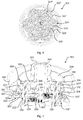
- Fig 1a and 1b illustrates a modular drive train arrangement 1 for a wind mill.
- the drive train 1 comprises an input module 2, a first gear module 3 being an eight stepped and stacked compound planet gear arrangement and a second and a second gear module module 4 beeing a six stepped and stacked compound planet gear arrangement and finally a generator module 5.
- the input module 2 is fixed to a base frame 6, which may be fixed to the nacelle (not shown) of a wind mill (not shown).
- the drive train exhibits a longitudinal axis extending centrally from the input module 2 to the generator module 5.
- the input module 2 comprises a mounting disc 2' which is rotational about the longitudinal axis and arranged for allowing fixation of radially extending wind turbine blades (not shown).
- the first step module 3 comprises a splined shaft 3' which is inserted into a hollow input shaft (not shown) with corresponding splines (not shown) of the input module 2.
- the input shaft is connected to the mounting disc 2' for transmitting rotational movement and torque from the turbine to the first module 3.
- the second module 4 comprises an input gear 4', which is inserted into the first module 3, when mounted. As will be explained more in detail below, the input gear 4' of the second module 4 forms an output sun gear of the first module 3.
- the generator module 5 is provided with a generator input gear 5' that in the same manner is inserted into the second module 4 and there forms the sun wheel of the second gear module.
- the generator module 5 is further provided with a brake disc 5" which is fixed relative a rotor (not shown) of the generator module 5, which in turn is connected to the generator input gear 5'.
- a braking force to the breaking disc 5", e.g. by means a clamping friction device (not shown) it is thus possible to slow down the rotation of the generator rotor, the entire drive train 1 and the wind turbine.
- This modular arrangement of the entire drive train 1 affords for great advantages with regard to assembly, de-assembly and maintenance of the drive train.
- the arrangement allowing axial insertion and removal of the different modules into and out of each other greatly reduces the space needed for servicing, repairing and replacing the modules. Thereby the interior space of the nacelle housing the gear train may be kept at a minimum.
- Fig. 2 illustrates, in a schematic and simplified manner, the general concept of a compound planet gear, according to one embodiment, which may be used in either of or both gear modules 3, 4 shown in fig. 1a and 1b .
- the compound planet gear 100 illustrated in fig. 2 comprises a ring gear 110, a number of planet gear units 120 and a sun gear.
- the compound planet gear 100 should comprise at least two planet gear units for achieving the desired distribution of the load to several pairs of gear flanks being simultaneously in engagement, when transmitting a torque from the ring gear 110 to the sun gear 130.
- the number of planet gear units is typically three or four.
- the number of planet gear units may be doubled, thus typically resulting in six or eight planet gear units. The load to be sustained by each gear flank of the ring gear, the planet gear units and the sun gear is thus reduced to the total load divided by the number of planet gear units.
- the planet gear units 120 each comprise a primary planet gear 121 having primary teeth 121' meshing with the ring gear 110 and a secondary planet gear 122 which is connected axially to the primary planet gear 121.
- the secondary planet gear 122 is provided with secondary teeth 122' which meshes with the sun gear.
- the planet gear units further comprises a shock absorbing transmission arrangement which allows the secondary teeth 122' to preform a limited elastic rotation relative to the primary teeth 121'.
- Fig. 3 illustrates an example of how such a shock absorbing transmission unit may be arranged.
- the transmission unit 20 comprises a circular drive disc 21 which is non-rotationally fixed to a planet shaft 22.
- the planet shaft 22 is provided with splines (not shown) such that the drive disc 21 and a primary planet gear (not shown in fig 3 ) may be non-rotationally fixed to the planet shaft 22.
- the drive disc 21 is provided with a number of cylindrical pins 23 which are fixed to the drive disc 21 and extend in parallel with the planet shaft 22.
- the pins 23 are evenly distributed in the circumferential direction and in the shown example, nine such pins 23 are arranged on the drive disc 21.
- Each pin 23 is received in a respective elastic member 24.
- the elastic members 24 comprise an elastic and resilient material, such as natural or synthetic rubber.
- the elastic and resilient material of each elastic member is formed as a cylindrical sleeve, having a cylindrical envelope surface and an axially and centrally extending cylindrical bore.
- the elastic members further comprise an inner cylindrical metal sleeve 24' received in the cylindrical bore and an outer cylindrical metal sleeve 24" surrounding the envelope surface of the elastic and resilient material sleeve.
- the inner 24' and/or outer 24" metallic sleeves are preferably fitted to the elastic and resilient material by press fitting such that the elastic and resilient material is compressed and thereby pretensioned when mounted.
- the transmission unit 20 further comprises an annular cog wheel member 25 with peripheral teeth 25' and a circular transmission disc 26 with a number of cylindrical through openings 26' and a central cylindrical bore 26" for receiving the planet shaft 22.
- the number and positioning of the through openings 26' correspond to the number and positioning of the pins 23.
- the trough openings 26' are further dimensioned such that the elastic members 24 may be received therein with a tight fit.
- An annular slide bearing 29 is arranged between the drive disc 21 and the annular cog wheel member 25 for allowing relative rotation there between.
- the annular cog wheel member 25 and the transmission disc 26 are provided with a plurality of mutually corresponding mounting holes 25", 26'" for the reception of mounting bolts 28.
- the mounting holes 26'" of the transmission disc 26 are elongate in the peripheral direction of the transmission disc 26, such that the relative angular position between the annular cog wheel 25 and the transmission disc 26 may be adjusted before tightening the mounting bolts 28. This is an important feature since it allows the relative angular position between the primary planet gear fixed to the planet shaft 22 and the annular cog wheel member 25, i.e. between the primary and secondary planet teeth to be adjusted when mounted.
- a nominal angular adjustment may be carried out for all transmission units comprised in the drive train, such that all drive train cog flanks simultaneously in engagement may experience equal nominal load.
- the transmission unit 20 also comprises a central bearing 27 which is arranged coaxially around the planet shaft 22 between the drive disc 21 and the transmission disc 26.
- the bearing 27 may be a slide bearing or a roller bearing which allows small rotational relative movements between the drive disc 21 and the transmission disc 26.
- the elastic members 24 are formed of standard bushings which are commercially available.
- the limited elastic relative rotation between the primary planet teeth and the secondary planet teeth may however also be accomplished in many other ways.
- the drive disc may be provided with axially protruding and radially extending support members which form opposing first support surfaces facing generally in the circumferential direction of the drive disc.
- the transmission disc may comprise corresponding second support surfaces facing a respective first support surface.
- a resilient member, such as compression spring, a leaf spring, or a resilient bussing may be arranged between each pair of opposing first and second support surface, such as to allow the transmission disc and annular cog wheel member to be limitedly and resiliently rotated relative to the drive disc and the primary gear.
- shock absorbing transmission units comprised in the planet gear units it is possible to choose the ratio between the applied torque and the maximum relative rotation. It may e.g. be suitable to design the transmission unit such that the relative rotation between the primary planet teeth and the secondary planet teeth is approx. 2-4° at maximum torque. However, also other torque to relative rotation ratios may be used.
- Figs 4 and 5 illustrate an exemplifying non-stacked compound planet gear 200 according to the invention.
- a planet gear may be used as a single step, a first step , a second step or any additional step gear in a gear arrangement.
- the compound planet gear 200 is illustrated for use as e.g. a single stepped planetary gear or adapted as a first gear module for a drive train.
- the compound planet gear 200 comprises a splined input shaft 203.
- the input shaft 203 is fixed to and extends through a ring wheel carrying disc 205 which in turn is fixed to a ring wheel 210.
- Three shock absorbing planet gear units 220 are arranged in meshing contact with the ring wheel 210 and a sun wheel 230.
- the shock absorbing planet gear units 220 are constructed as the planet gear unit 120 described above with reference to figs. 2 and 3 and are not further described in detail here.
- the planet shafts 223 of the planet gear units 220 are journaled in bearings 224 to a planet carrier 225 which forms a stationary part. Also the input shaft 203 is journaled in bearings 226 to the planet carrier 225.
- the primary planet gear 221 of each planet gear unit 220 is meshing with the ring wheel 210 and the secondary planet gears 222 are meshing with the sun wheel 230.
- the sun wheel 230 is fixed to a first step output shaft 231 which is journaled in bearings 232 inside the hollow input shaft 203.
- Each shock absorbing planet gear unit 220 forms, together with bearings 224 and a bearing hub 224a a chock absorbing planet gear module.
- the bearing hub 224a has a larger diameter than the primary planet gear 221 such that the planet gear module may be mounted and dismounted axially from below.
- the planet gear module further comprises at least one spline arrangement for facilitating assembly, de-assembly and maintenance.
- the compound planet gear further comprises a housing 240 comprising side walls 241 and a bottom wall 242.
- the housing 240 together with the ring wheel carrying disc 205 with slide bearings 243 and the output shaft 231 with bearings 232, sealingly encloses and interior space.
- the compound planet gear 200 with housing 240 forms a module.
- the housing 240 may thus contain a lubrication media, such as oil, which is encased in the module and which may thus be different from the lubrication media used in the other parts and modules of the entire drive train arrangement.
- the first module may also be readily mounted to and from an input module of the drive train arrangement by axial insertion and withdrawal.
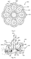
- Figs. 6 and 7 illustrate a six stepped and stacked compound planet gear arrangement 300 according to the invention.
- a stacked planet gear arrangement may be used as a single first gear step module or a second gear step module as shown in fig. 1b or in other gear arrangements.
- the stacked compound planet gear 300 is illustrated for use as a second gear step.
- the stacked compound gear 300 thus corresponds to gear module 4 shown in figs. 1a and 1b .
- the six stepped and stacked compound planet gear 300 comprises an input gear 303 mounted on an input shaft 304. As described above, that gear corresponds to the sun gear of the first gear module 3 in the drive train 1 shown in figs 1a and 1b .
- the input shaft 304 is fixed to and extends through a ring wheel carrying disc 305 which in turn is fixed to a ring wheel 310.
- the input shaft 304 is journaled in strong bearings 336 to a planet carrier 225.
- Six shock absorbing planet gear units 320 are arranged in meshing contact with the ring wheel 310 and a sun wheel 330.
- the planet gear units 320 are generally constructed as the planet gear unit described above with reference to figs. 2 and 3 .
- the set of planet gear units 320 comprises three first planet gear units 320' and three second planet gear units 320'.
- the planet shafts 323' 323" of the first 320' and second 320" planet gear units are equally long and longer than the planet shafts 220 shown in figs 3 and 4 .
- the first 320' and second 320" planet gear units differ only in that the secondary planet gears 322" of the second gear units 320" are arranged at a radial plane which is arranged at a greater distance from the primary gears 321', 321" than the radial plane at which the secondary planet gears 322' of the first gear units 320' are arranged.
- the planet shafts 223', 223" of the planet gear units 320', 320" are journaled in bearings 324 to the planet carrier 325.
- the primary planet gears 321', 321" of each planet gear unit 220', 320" is meshing with the ring wheel 310.
- an auxiliary centring shaft 350 has been installed.
- the centring shaft 350 is supported by an annular flange forming a centring device 351.
- the input shaft 304 extends to, without coming into contact with, the centring device 351.
- the envelope surface of the centring shaft 350 forms a sun wheel and the secondary planet gears 322', 322" are meshing with the sun wheel of the centring shaft, at different axial planes.
- Such an auxiliary centring shaft may 350 be used as a temporary aiding means for mounting and nominal adjustment of the shock absorbing planet units 320', 320".
- the six stepped and stacked compound planet gear 300 further comprises a housing 340 comprising side walls 241 and a bottom wall 342 provided with a central opening.
- the housing 340 forms a flange unit 340' for connecting the gear step modules to each other
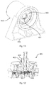
- Fig. 8 shows the six stepped and stacked compound planet gear arrangement 300 as being the second gear step module in the drive train 1 in fis 1a and 1b, when a generator module 500 or 5 has been mounted thereto.
- the auxiliary centring shaft 350 shown in fig. 7 has been removed and an input shaft 501 of the generator module 500 has been inserted through the central opening 333.
- the generator's input shaft 501 is steadily supported by bearings arranged at both ends of the shaft and is at the protruding end provided with external teeth forming a sun wheel 330.
- the sun wheel 330 meshes with the secondary planet gears 322', 322".
- the generator module 500 further comprises a an annular flange 502 which is received in a flanged opening 333 arranged in the bottom wall 342.
- the housing 340 together with the ring wheel carrying disc 305 with slide bearings 343, the bottom wall 342 and the generator shaft 501 and flange 502, sealingly encloses and interior space.
- the stacked compound planet gear 300 with housing 340 forms a second gear step module corresponding to the second step module 4 shown in fig. 1b .
- the housing 340 may thus contain a lubrication media, such as oil, which is encased in the module and which may thus be different from the lubrication media used in the other parts and modules of the entire gear arrangement.
- the second step module may also be readily mounted to and from the first step module of the gear arrangement by axial insertion and withdrawal.
- the generator module 500 comprising a generator input gear which is constituted by the sun wheel 330 once it has been used for the assembly and adaption of the shock absorbing units 320, it is withdrawn and adapted to generator shaft 501.
- the generator module may readily be mounted to and removed from the second gear step module by axial insertion and withdrawal through the hole in the bottom wall 342.
- Figs. 9 and 10 illustrate an eight stepped and stacked compound planet gear arrangement 400 that represent the first gear module in the drive train 1 in figs 1a and 1b .
- This stacked compound planet gear 400 is similar to stacked compound planet gear 300 shown in figs 6 and 7 .
- the planet gear 400 differs from planet gear 300 in that it comprises eight shock absorbing planet units 420.
- the set of planet units 420 comprises four first planet units 420' and four second planet units 420".
- the secondary planet gears 422" of the second planet units 420" are arranged at a greater axial distance from the primary gears 421', 421" than the secondary planet gears 422' of the first planet units 420'.
- the stacked compound planet gear 400 comprises an input shaft 404 which is fixed to and extends through a driving ring wheel carrying disc 405.
- the input shaft 404 is journaled in strong bearings 426.
- the input shaft 404 extends axially towards, but does not contact a centring unit 450 which is rigidly fixed to the housing 440.
- the centring unit 450 comprises a number of through holes, electrical wires 451 and pipes 452 which extend into and axially through the hollow input shaft 404.
- the electrical wires 451 and the pipes 452 are connected with regulating devices arranged at the hub of a wind turbine (not shown).
- regulating signals and hydraulic fluids may be conducted from the first gear step of the entire gear arrangement to the wind turbine for regulating the different functions, e.g. the pitch of the wind turbine.
- An important advantage of such an arrangement comprising a centring unit 450 arranged at the first gear step and a hollow input shaft 404 is that all pipes and wires needed for controlling the turbine extend from the turbine only to the first step of the gear arrangement. Thereby there is no need for extending the pipes and wires further down stream the gear arrangement. I.e. it is not necessary to arrange pipes or wires through the second gear step, through any possible further gear step or through the generator.
- essentially no further through holes or openings a required in the central axle of the drive train, downstream of the first gear step. This in turn makes it possible to reduce the diameters of the sun wheels thereby to achieve great gear ratios by utilising merely two stacked compound planet gears arranged in a first and second gear step respectively.
- the centring unit 450 further functions as a support for a centring shaft 455 carrying a sun wheel 430, which may be used when mounting and adjusting the nominal load of the shock absorbing planet units 420.
- Fig. 11 illustrates an input module 600 which is fixed to a base frame 610.
- the input module 600 corresponds to input module 2 shown in figs. 1a and 1b .
- the base frame 610 is fixed to the nacelle (not shown) of the wind mill.
- the input module 600 further comprises a hollow input shaft 620 which is fixed to a mounting disc (not shown) for fixation of a wind turbine (not shown).
- the input shaft 620 is provided with internal splines 621 which corresponds to external splines 403 on a first step input shaft 404 of a first step gear module 400 shown in fig. 12
- Fig. 12 illustrates the eight stepped and stacked compound planet gear arrangement 400 shown in fig. 10 and being the first gear module in figs. 1a and 1b .
- the gear module400 is also provided with splines 403 to receive torque from the input module 2, 700 and transfer torque to the ring gear of the first gear module.
- Figs 13 and 14 illustrate respective embodiments of an input module 700, 700'.
- the input module 700, 700' comprises a central hollow inner shaft member 710, 710', which is fixed to an annular mounting disc 711, 711'.
- the mounting disc 711, 711' is used for fixing the turbine blades (not shown) of the wind turbine to the gear arrangement.
- the mounting disc 711, 711' is at its periphery fixed to an outer hollow shaft member 712, 712'.
- the outer shaft member 712, 712' is arranged coaxially around the inner shaft member 711, 711'.
- the outer shaft member 712, 712' is further journaled in strong bearings 713, 713' to a solid casing or housing 714, 714' of the input module 700. Since the housing 714, as seen in fig. 13 , is fixed to the nacelle (not shown) also the bearings 713, 713'are indirectly fixed to the nacelle. By this means the outer shaft member 712, 712' is strongly supported and it may sustain and absorb strong axial, radial and bending forces acting on the mounting disc 711, 711' when the turbine is exposed to strong, transient and turbulent wind flows.
- the inner shaft member 710, 710' may be made comparatively weak and may be dimensioned mainly to transmit torsional forces from the mounting disc 711, 711' to the first step gear.
- the inner shaft member 710, 710' may be made comparatively weak and may be dimensioned mainly to transmit torsional forces from the mounting disc 711, 711' to the first step gear.
- Such a torsional flexibility of the inner shaft member 710, 710' thus acts in combination with the shock absorbing planet units to protect the gear arrangement and to smoothen the drive of the gear arrangement and generator.
- the arrangement of the coaxial shaft members 710, 710', 712, 712'being supported by the housing 714, 714' also allows the input module to be designed with comparatively small dimensions.
- an input module for connecting a driving device to a driven device comprises and inner tubular shaft, an outer tubular shaft and a surrounding housing, wherein the inner tubular shaft is arranged coaxially inside the outer tubular shaft and the outer tubular shaft is journaled in bearings to the housing and wherein a respective first end of the inner and outer tubular shafts are connected by means of a mounting disc arranged for fixation of the driving device.
- Fig. 15 illustrates the entire gear arrangement 800 according to one embodiment.
- the gear arrangement 800 corresponds to the arrangement shown in figs. 1a and 1b and comprises an input module 810, a first gear module 820, a second gear module 830 and a generator module 840.
- the modules are fixed to each other axially one to the other.
- Each module further encloses a sealed interior space or a compartment, such that the different compartments may contain different lubrication media and other differing atmospheres as may be needed.
- Each compartment of the first gear step module 820 and the second gear step module 830 is further divided into sub-compartments 820a, 820b and 830a, 830b respectively.
- each sub-compartment and the bearings arranged therein may be individually provided with lubrication and cooling.
- the housings of the respective modules may be provided with pipes, tubes and/or channels for conducting lubrication and/or cooling media.
- the first step module 820 and the second step module 830 comprises a number of planet shafts 821, 831 forming part of a respective shock absorbing planet unit as described above.
- the planet shafts 821, 831 are rotationally and coaxially arranged around a respective control rod 821, 831.
- Fig. 16 illustrates one such a control rod 821 in enlargement and in greater detail.
- the control rod 821 may be provided with axial channels 851, pipes 852, and wires 853.
- Such channels, pipes and wires may be used for sensing and monitoring different conditions of e.g. the bearings, the lubrication and the atmosphere in within the different compartments. These components may also be used for adjusting such conditions, e.g. by adding lubrication.
- the control rods 821, 831 may be provided with radial channels 855 extending from the axial channels 851 to the periphery och the control rod 821.
- control rods 821 my exhibit circumferential groves 856 for allowing sealings, such as o-rings to define certain zones within the compartments. Such zones may be used e.g. for monitoring and regulating the atmosphere and conditions of a bearing or the like.
- the control rods 821, 831 may be formed in any suitable material such as polymer material, metal or a combination thereof.
Abstract
A compound planet gear arrangement (100, 200, 300, 400) having a ring gear (no, 210, 310, 410), at least two planet gear units (120, 220, 329, 429) and a sun wheel (130, 230, 330, 430). Each planet gear unit comprise a primary planet gear (121, 221, 321, 421) with primary planet teeth meshing with the ring gear and a secondary planet gear (122,222, 322, 422) with secondary planet teeth meshing with the sun gear. The secondary planet gear is axially connected with the primary planet gear. Each planet gear unit (120, 220, 320,420) comprises a shock absorbing transmission arrangement (20) which is arranged to allow a limited elastic rotation of the second planet teeth relative to the first planet teeth. A drive train arrangement comprising sucha compound planet gear arrangement is also disclosed.
Description
- The invention relates to a compound planet gear for transmitting torque by splitting the torque into several torque transmitting gear components. The invention also relates to a gear arrangement comprising at least two such compound planet gears forming a respective gear step of the gear arrangement.
- There are many applications where there exists a need for transforming rotational motion or torque into another rotational motion and torque. In most cases some kind of planetary and compound planetary gear arrangements may be used for such rotation to rotation arrangements.
- Examples of such applications are devices as wind and fluid power mills where it is necessary to transform high torque at low RPM to lower torque with higher RPM. Other examples are motors in cars and trucks, turbines, electric motors and other driving arrangements where it is necessary to convert high RPM and low torque to high torque with low RPM.
- At gear arrangements, such as planetary gears, where the transmitted torque is split between several gear components there exists a problem with over determination of the gear arrangement. Such over determination may lead to unbalanced load and uneven wear of the gear components. The present invention is concerned not only with solving problems related to over determination but also to provide shock absorption to reduce transient forces occurring in the gear arrangement when the transmitted forces through the gear arrangement changes drastically. At these types of gear arrangements it is of vital interest that the entire arrangement is durable and has a long and predictable service life. A further important aspect is that volume-weight ratio is as low as possible to the gear-ratio.
- The present invention may be used at various applications of the above mentioned type and also in others. An application of certain interest to demonstrate how the present invention can improve the functionality of gear arrangement is the wind power generation industry. In this industry planetary gearboxes play a central part of the driveline from the turbine or rotor blades to the generator for generation of electrical power.
- Turbulent winds changes due to large masses in motions, the propeller and generator, give rise to sudden and strong changes of the force direction through the gearbox. This change of direction together with the air gap and stiffness within the gearbox drive train results in shock waves and high overloads on the meshing teeth and in the bearings. Metal contacts between the gear teeth, will contaminate the oil in the gearbox. Optimizing oil qualities to RPM viscosities and cleanness is very important. To extend the lifetime even further it is necessary to create gearboxes where vulnerable parts can be replaced in place with new better optimized components, such as bearings and gears.
- Furthermore, as described in NREL Conference paper; NREL/CP-5000-55355; "Dynamic Analysis of Wind Turbine Planetary Gears Using an Extended Harmonic Balance Approach, Preprint dated June 2012, by Y. Guo, J. Keller and R. Parker, transient forces is very common in windmills and might have a negative lifetime factor on this kind of arrangement to achieve even distributions of split torque through the gearboxes.
- The cause of the low lifetime of windmill gearboxes is still not fully known though many different kinds of epicyclical gearboxes have been tested. Many windmill manufacturers are today looking for direct driven permanent magnet though they become very large, heavy and expensive using earth metal that is a limited recourse.
- A gearbox is a device for power transmission which changes the rotation speed, torque and / or rotation from one rotating shaft to another. This power transfer between the axles is usually made through a collaborative meshing between two cylindrical gears. This means that only two tooth sides at a time with the rolling and sliding movements transmit the current torque. The meshing must, with its two mating tooth flanks, be dimensioned for the torque transmitted between the gears. This may be done by varying the gear diameter, width and meshing. Gear materials and hardness of the tooth flanks as well as the oil that lubricates the gearbox naturally constitute extremely important factors for increased strength and increased resistance to mechanical abrasions. In cylindrical gear boxes an upshifting occurs when a larger diameter driving gear meshes with a gear with smaller diameter driven gear. Correspondingly, downshifting occurs when a smaller diameter driving gear meshes with a larger diameter driven gear. At applications requiring high up- or downshifts, several gear steps can be needed. A first step of e.g. 1: 5 could be complemented by a second step of e.g. 1: 5, resulting in a total upshift of 1:25. If two meshing tooth flanks must be adapted for large input torques such as e.g. at extraction of wind energy to generate electrical energy, cylindrical gear arrangements can lead to large and heavy gearboxes in relation to its gear ratio. To avoid this problem various different planetary gearboxes have been suggested for providing a compact, energy-dense gear arrangement with high speed ratio, where speed ratio is to be understood as input speed in relation to output speed of the input and output shafts of a gear box.
- The planetary gearboxes are built around three types of elements, the planetary gear, planet carrier and the main gear consisting of an outer ring gear or ring wheel and an internal sun gear or sun wheel. With this type of gearbox it is possible to split incoming torques onto several planet gears that are cooperating in transforming torque through the gearbox, between the ring gear and the sun gear.
- The planetary gearbox can be made in many ways, but most usually as a single or a compound transmission gearbox. In single planetary gearboxes, a number of single planetary gears transform torque directly between the ring gear and the sun gear.
- In compound planetary gear transmissions the torque is transmitted from the ring gear to the sun gear via a number of planetary gear sets, each planetary gear set comprising at least two planetary gears one of which is meshing with the ring gear and one of which is meshing with the sun gear. The planetary gears in each set may, in compound planetary gearboxes, either be in meshing contact with each other or, as in stepped compound planetary gearboxes, be fixed to each other by means of a common shaft. Such compound planetary gear arrangements can generate higher speed ratio than single planetary transmission gear boxes.
- The planetary gear box carrier can in some embodiments be connected to the transmission input/output shaft, and thus, with a fixed ring gear, transform torque through its rotating planetary gears to the sun gear and its connection to the output/input shaft. In other examples, the carrier may be fixed to the gearbox which in turn means that the ring gear is connected to the gearbox input/output shaft. The rotating ring wheel conveys thus torque through the fixed planetary carrier with its rotating planetary gears that transform torque to the sun gear that is connected to the output/input shaft.
- It is extremely important with split transmission that the transforming of torque is evenly distributed onto the cog flanks that are involved.
- With three planetary gears used in a single planetary gear box construction, the sun gear can be centred through the three planetary gear tooth flanks, and by physical and geometric reasons give possibilities to generate even force transmission distribution between the ring gear and sun gear.
- In many planetary gear boxes, used for wind turbines, cars etc., three planetary gears in 1-3 steps as single planetary constructions are used to convey incoming primary torque between the ring gear and sun gear.
- With three planetary gears in a single transmission gearbox it is possible to achieve a gear ratio of about 1:12. At this high gear ratio the sun wheels and its shaft will be disproportional in size and thus usually lower gear ratios are used in practice. With four planetary gears in a single planetary gearbox it may be possible to accomplish a gear ratio of about 1:5,2, with six planetary gears approx. 1:2,5 and with eight planetary gears approx.1:2, before the planetary gears starts to hit each other.
-
US patent 6,459,165 concerns wind power generation and discloses a two-stage planetary gearbox with three planet gears in each step. The rotating planet carrier of the first stage transmits torque through three planetary gears to a sun gear centred through the planetary gear tooth flanks. This sun gear conveys further the torque via a driving mean to rotate the planet carrier in the in a second step that trough three additional planetary gears transform tongue to a sun wheel attached to a shaft powering the generator at a total gear ratio of approximately 1:16. In other patens similar arrangements are further equipped with another planet gear stage and or fixed-axis gear systems to improve the gear rate and reduce the size, weight and cost of the generator. By such arrangements with three planet gears the first sun gear, the second planet carrier with its three planets and helical cut cogs will create free floating unit centred and stabilized by only the cog wheel flanks. - In theory, the above arrangement should not involve over determination problems but gravity may be a certain concern.
- Another downside to use only three planetary gears in the first step is that a large primary torque only can be divided on to three pairs of cog wheel flanks which require large cog wheel diameters and sizes to cope with torque that is transformed over three planetary wheels and the sun wheel. The load onto the bearings will be high resulting in bearings having larger sizes and diameters that even can be larger than the gear itself, if not hydro mechanical plain bearings are used. Further, larger diameter ball or roller bearings reduce their tolerances to RPM according to an exponential function.
- In other planetary gear boxes, used for wind turbines, cars etc, four planetary gears in 1-3 steps are used to convey incoming primary torque between the ring gear and sun gear. Splitting the incoming torque into 4 pathways through the gearbox will decrease the sizes of the gears and bearings but will also reduce the gear ratio to be about 1:4. Further, in these cases there are no possibilities to have a free floating sun gear. Instead, even load distribution is here sought to be achieved by increasing the precision in the manufacture of gears, shafts, bearings, centring, elasticity, etc.
- In order to further minimize over determinations, gear shafts some times are equipped with a flex pin arrangement such as disclosed in
U.S. Pat. No. 3,303,713 . - Single step planetary gear arrangements comprising four planetary gears allow, due to geometrical reasons, gear ratios at a maximum of about 1: 5,2 and in practice usually a gear ratio of 1:4 is achieved. When arranged as a two step gear arrangement this will give a gear ratio of 1:16. In order to improve the gear ratio and reduce the size of the driven generator a third planetary gear stage may be added such as disclosed e.g.
US patent 8,907,517 . In other known arrangements, a third gear step may be arranged as a fixed axis gear system that also solves the other big issue in gear trains concerning wind power to have a central open contact through the hole in central shaft for power support and control of the wind turbine. - Compound planetary gearboxes, some times referred to as hybrid stepped planetary solutions, have two linked planetary gears, a primary and a secondary, with different diameters, fixed onto one common shaft in one compound gear step. This arrangement transform torque with high theoretical gear ratio, but with consideration of other issues concerning the gearbox, the gear ratio with three pairs of linked planetary gears in practice will be in a region of 1:15 to 1:20.
- Even though such compound stepped planetary gear arrangements theoretically exhibits great gear ratios, compact constructions, high energy densities and high speed ratios, the stepped planetary gears have not in practice been used to a large extend within e.g. the windmill industry. It has turned out that such known stepped gear arrangements frequently exhibits the following problems:
- They require very precise machining and measurements to prevent over determination, due to double meshing contacts between two different gears with an exact fixation to one common shaft makes manufacturing and assembling more difficult and results in greater risks of failure.
- Stepped planetary gears with four planets at the same level will reduce the gear rate and make this solution less attractive.
-
US 2010/0113210 A1 discloses a compound planetary gearbox where the secondary planet gears are stacked in two axial levels thus creating a split torque from an internally geared ring wheel to a central sun gear. The document discusses the problem of over determination but fails to suggest at a satisfactory solution usable for all embodiments described therein. - In
US 8,734,289 B2 a plurality of identically shaped first and second planet shafts equipped with a primary and a secondary planet gear that are stacked both in axial and with the second planet shaft in radial directions forming a sector to transform split torque from an external ring gear to a central sun gear. Smaller diameter gears will provide better machining and measuring conditions to achieve even flank pressures on the involved gears. The drawback is an extra gear step to achieve the same gear rate as e.g. is described inUS 2010/0113210 . -
US 2003/0015052 A1 presents a gearbox with a plurality of identically shaped first, second and third planet shafts equipped with a primary and a secondary planet gear where the first and second planet shafts with their planets are stacked on both sides of an externally cut ring gear, forming two sectors with two first planet shafts that with their planet gears are meshed together with the planet gears of the second planet shaft and where these two sectors are mashed together with the third planet shaft and its planet gears to transform half of the torque generated by the ring gear as split torque to a driving shaft of an generator. - Stacking the second planetary gears in two levels improve the possibilities to achieve high speed ratios and double the split torque gear functions through the gearbox, but will result in that six, eight or more cogwheels in further different positions in the gearbox have to be secured to mesh with even cog-flank pressures.
- At higher torques to be transmitted through the gearbox, at least one of the gears has to be fixated to the shaft by e.g. splines that further dramatically increase the risk of misalignment and create over determinations of one or many cog-flanks.
- Larger cogwheels are difficult to measure and adjust to have exact masking parameters.
- A damage report concerning all Swedish windmills made by the Swedish Elforsk report 10:50 2011 and CIRP Annals - Manufacturing Technology 61 (2012) 611-634 concluded that the gearboxes generally not lasted longer than about half the promised service life of 20 years. The result shows that the gearbox designers fails to take all the internal dynamic forces into consideration.
-
US patent 4,674,351 discloses a compliant gear. The document describes that earlier attempts to create compliant gears to be used for shock absorbance, reduced tolerances requirements between meshing gears and noiseless gears has failed due to lack of radial stiffness to maintain centreline distance between the meshing gears. The document suggests to increase the radial stiffness of the compliant gear by intrusion of rigid shim as sandwich construction between a compliant laminate. That was followed by other similar constructions likeUS 4831 897A or just by providing the gear with bendable sprockets inside cogwheelWO2007119074A1 or in a hub connected to the cogwheel as inDE102007053509A1 . - An object of the present invention is to provide an enhanced compound stepped and/or stacked planet gear.
- Another object is to provide such a compound planet gear having shock absorbing properties for reducing the negative effects of transient torque variations acting on the input shaft.
- A further object is to provide such a compound planet gear which efficiently reduces the problems caused by over determination, at a high degree of freedom.
- A still further object is to provide such a compound planet gear exhibiting a high gear ratio, high energy density and high speed ratio.
- Yet another object is to provide such a compound planet gear which may easily be assembled and disassembled and which readily allows maintenance.
- Still another object is to provide such a compound planet gear, which allows for that a wind turbine arranged to drive the gear box may be readily controlled in a space saving manner while requiring only small modifications of a limited part of a gear arrangement connecting the turbine to a generator.
- Another object is to provide such a compound planet gear at which the dimensions of constituent components, such as sun wheels, may be kept small while still allowing optimal gear ratios.
- Yet another object is to provide such a compound planet gear, which allows for that a composed gear arrangement forming a drive train may be readily assembled by combining modular components.
- A further object is to provide such a compound gear which is adapted to be used in windmills for efficient extraction of electric energy from heavily varying winds exhibiting large degrees of turbulent flows.
- These and other objects are achieved by a compound planet gear as set out in the preamble of
claim 1 and exhibiting the special technical features specified in the characterizing portion ofclaim 1. The compound planet gear comprises a ring gear, at least two planet gear units and a sun wheel. Each planet gear unit comprise a primary planet gear with primary planet teeth meshing with the ring gear and a secondary planet gear with secondary planet teeth meshing with the sun gear. The secondary planet gear is axially connected with the primary planet gear. Each planet gear unit comprise a shock absorbing transmission arrangement which is arranged to allow a limited elastic rotation of the second planet teeth relative to the first planet teeth. - The shock absorbing transmission arrangement thus allows an elastic relative rotation between the primary planet gear and the secondary planet gear. By this means heavy rotational accelerations and retardation of one of the planetary gears is smoothly absorbed by the other planet gear, thereby preventing heavy impacts when one cog flank comes into contact with a corresponding cog flank of the meshing gear.
- When used e.g. at windmill installations, winds with heavily varying forces and with turbulent flows causes the rotational speed of the rotor to vary momentarily. This in combination with the momentum of the gear arrangement and a generator connected thereto will continuously cause cog teeth of one gear to be forced into high frequently altering contact with neighbouring cog flanks of two cog teeth at a meshing gear. The inventive shock absorbing transmission arrangement efficiently reduces the impact of such altering contact and prevents heavy rotational accelerations and retardations on the input shaft to be transmitted to gears arranged downstream of the transmission unit.
- In addition to the shock absorbing effect, the transmission units also greatly reduces the problems caused by over determination of split torque transmission in planetary gears. Since the secondary planet gears are limitedly and elastically rotational relative to their respective primary gear, each secondary gear may individually adjust its engagement with the sun gear such that the total load of the gear arrangement is evenly distributed between all cooperating cog flanks momentarily being in engagement.
- By this means, the compound planet gear and its constituent parts may be designed with comparatively small dimensions while still being able to withstand high and greatly momentarily varying torques. This in turn allows for that the compound planet gear may be designed with high energy density, high gear ration and high speed ration. The load distributing effect of elastic transmission arrangements also reduces the wear of all cog flanks involved in transferring torque through the compound planet gear, thereby greatly enhancing the service life of the entire arrangement.
- The transmission arrangement may also be understood as a compliant gear, which is arranged to be used for shock absorbance, for reducing the required tolerances between meshing gears and splines and for reducing noise in such a way that the radial stiffness is not jeopardized even though the possible compliance functions in this transmission arrangement is comparatively much higher than in previously known compliant gears. The high compliance functions are well adapted to be used in compound stepped and stacked planetary gearboxes and will in e.g. a drive train consisting of two stepped and stacked compound gearboxes according to the present invention, due to the high speed ratio generate very high compliance characteristics between the input and output torque in thedrive train. If these gear arrangements are used in windmills they will to a large extent smooth and even prevent the change in torque directions that often occurs between the turbine, rotor or propeller and the generator during e.g. turbulent winds.
- Each transmission arrangement may comprise a number of elastic members arranged to transmit torque between the first planet teeth and the second planet teeth.
- Each transmission arrangement may comprise a drive disc which is fixable to a shaft connecting the first planet gear with the second planet gear and which is provided with a number of axially extending pins fixed to the drive disc; and a cog wheel provided with peripheral teeth and comprising a transmission disc provided with a number of openings corresponding to the number of pins, wherein an annular elastic member is received in each opening and a respective pin is received in each elastic member.
- In such case the peripheral teeth of the cog wheel may form the second planet teeth and the drive disc may be non-rotationally fixed to the first planet gear by means of a shaft.
- Advantageously, the planet gear unit may, together with bearings and at least one bearing hub form a planet gear module.
- Each elastic member may comprise an annular rubber bushing.
- Each elastic member may further comprise an inner metallic sleeve and an outer metallic sleeve.
- The compound planet gear may be a stacked planet gear comprising an even number of planet gear units with the primary planet gears arranged in a first radial plane and wherein half of the secondary planet gears are arranged in a second radial plane and half of the secondary planet gears are arranged in a third radial plane being arranged at a greater distance from the first radial plane than the second radial plane.
- The invention further concerns a drive train arrangement comprising a first compound planet gear as described above forming a first gear step and a second compound gear as described above forming a second gear step of the gear arrangement.
- The sun wheel of the first compound planet gear may then be connected to the ring gear of the second compound gear.
- The sun wheel of the second compound planet gear may further be connected to a rotor of an electrical generator.
- Alternatively, the drive train arrangement may comprise more than two compound planet gear steps, wherein the last gear step comprises a sun wheel which is connected to a generator or another utility appliance.
- The drive train arrangement may comprise a housing which is divided into at least a first compartment receiving the first compound gear and a second compartment receiving the second compound gear, wherein the compartments are sealed from each other, for allowing different lubrication media to serve the respective compartments.
- At least one of the first and second compartments may be divided into at least two sub-compartments.
- The drive train arrangement may further comprise an input shaft which comprises a first tubular shaft member which is connected to the ring gear of the first compound gear and a second tubular shaft member which is arranged co-axially around the first shaft member and fixed to the first shaft member by means of an annular mounting disc, wherein the second tubular shaft member is journaled in bearings to a housing of the gear arrangement.
- The first tubular shaft members may be comparatively weak and arranged mainly to transmit torque from the mounting disc to the ring gear of the first compound gear and the second tubular shaft together with the housing may be arranged to absorb axial, radial and bending forces from the mounting disc.
- A turbine, such as a wind turbine, may be fixed to the mounting disc.
- In the drive train arrangement, the first compound planet gear, the second compound planet gear and, when applicable, the generator and the input shaft may be arranged as separate modules which are arranged to be modularly assembled and de-assembled, module per module.
- The drive train arrangement may comprise control means for controlling a turbine mounted to the mounting disc extends from the first gear step or another gear step which is not the last gear step, axially through the first tubular shaft member of the input shaft to the mounting disc.
- Further objects and advantages of the compound planet gear and the gear arrangement appear from the following detailed description of embodiments and from the appended claims.
- Generally, all terms used in the claims are to be interpreted according to their ordinary meaning in the technical field, unless explicitly defined otherwise herein. All references to "a/an/the element, apparatus, component, means, step, etc." are to be interpreted openly as referring to at least one instance of the element, apparatus, component, means, step, etc., unless explicitly stated otherwise. The steps of any method disclosed herein do not have to be performed in the exact order disclosed, unless explicitly stated.
- The invention is now described, by way of example, with reference to the accompanying drawings, in which:
-
Fig 1a is a perspective view illustrating a drive train for a wind mill, which drive train comprises a gear arrangement according to an embodiment of the invention. -
Fig. 1b is an exploded perspective view of the drive train shown infig 1a . -
Fig. 2 is a schematic perspective view of a simplified compound planet gear according to one embodiment of the invention. -
Fig. 3 is an exploded perspective view of an example of a shock absorbing planet unit, which may be used in a compound planet gear according to the invention. -
Fig. 4 is a schematic and simplified top view of a three stepped compound planet gear arrangement according to the invention. -
Fig. 5 is a more complete semi section in perspective of the three stepped compound planet gear arrangement shown infig. 4 . -
Fig. 6 is a schematic and simplified top view of a six stepped compound planet gear arrangement according to the invention. -
Fig. 7 is a more complete semi section in perspective of the six stepped compound planet gear arrangement shown infig. 6 . -
Fig. 8 is a semi section in perspective of a six stepped and stacked compound planet gear arrangement when mounted to a generator module. -
Fig. 9 is a schematic and simplified top view of an eight stepped and stacked compound planet gear arrangement according to the invention. -
Fig. 10 is a more complete semi section in perspective of the eight stepped and stacked compound planet gear arrangement shown infig. 9 . -
Fig. 11 is a perspective view illustrating some parts of an input module, which may form part of a drive train arrangement according to the invention. -
Fig. 12 is a semi section in perspective illustrating the eight stepped and stacked compound planet gear arrangement shown infig. 10 with some parts removed. -
Fig. 13 is a section in perspective illustrating an input module. -
Fig. 14 is a corresponding view illustrating an alternative input module. -
Fig. 15 is a semi section in perspective through an entire drive train arrangement and its lubrication alternatives according to an embodiment of the invention. -
Fig. 16 is a perspective view in enlarged scale illustrating a detail of the lubrication and control alternatives according to an embodiment of the invention. - The invention will now be described more fully hereinafter with reference to the accompanying drawings, in which certain embodiments of the invention are shown. This invention may, however, be embodied in many different forms and should not be construed as limited to the embodiments set forth herein; rather, these embodiments are provided by way of example so that this disclosure will be thorough and complete, and will fully convey the scope of the invention to those skilled in the art. Like numbers refer to like elements throughout the description.
-
Fig 1a and 1b illustrates a modulardrive train arrangement 1 for a wind mill. Thedrive train 1 comprises aninput module 2, afirst gear module 3 being an eight stepped and stacked compound planet gear arrangement and a second and a secondgear module module 4 beeing a six stepped and stacked compound planet gear arrangement and finally agenerator module 5. Theinput module 2 is fixed to abase frame 6, which may be fixed to the nacelle (not shown) of a wind mill (not shown). The drive train exhibits a longitudinal axis extending centrally from theinput module 2 to thegenerator module 5. Theinput module 2 comprises a mounting disc 2' which is rotational about the longitudinal axis and arranged for allowing fixation of radially extending wind turbine blades (not shown). - The
first step module 3 comprises a splined shaft 3' which is inserted into a hollow input shaft (not shown) with corresponding splines (not shown) of theinput module 2. The input shaft is connected to the mounting disc 2' for transmitting rotational movement and torque from the turbine to thefirst module 3. Thesecond module 4 comprises an input gear 4', which is inserted into thefirst module 3, when mounted. As will be explained more in detail below, the input gear 4' of thesecond module 4 forms an output sun gear of thefirst module 3. - The
generator module 5 is provided with a generator input gear 5' that in the same manner is inserted into thesecond module 4 and there forms the sun wheel of the second gear module. Thegenerator module 5 is further provided with abrake disc 5" which is fixed relative a rotor (not shown) of thegenerator module 5, which in turn is connected to the generator input gear 5'. By applying a braking force to thebreaking disc 5", e.g. by means a clamping friction device (not shown) it is thus possible to slow down the rotation of the generator rotor, theentire drive train 1 and the wind turbine. - This modular arrangement of the
entire drive train 1 affords for great advantages with regard to assembly, de-assembly and maintenance of the drive train. The arrangement allowing axial insertion and removal of the different modules into and out of each other greatly reduces the space needed for servicing, repairing and replacing the modules. Thereby the interior space of the nacelle housing the gear train may be kept at a minimum. -
Fig. 2 illustrates, in a schematic and simplified manner, the general concept of a compound planet gear, according to one embodiment, which may be used in either of or bothgear modules fig. 1a and 1b . - The
compound planet gear 100 illustrated infig. 2 comprises aring gear 110, a number ofplanet gear units 120 and a sun gear. For reasons of clarity, only one planet gear unit is shown infig. 2 but it is realized that thecompound planet gear 100 should comprise at least two planet gear units for achieving the desired distribution of the load to several pairs of gear flanks being simultaneously in engagement, when transmitting a torque from thering gear 110 to thesun gear 130. In embodiments comprising a non-stacked compound planet gear, the number of planet gear units is typically three or four. In stacked compound planet gears the number of planet gear units may be doubled, thus typically resulting in six or eight planet gear units. The load to be sustained by each gear flank of the ring gear, the planet gear units and the sun gear is thus reduced to the total load divided by the number of planet gear units. - As seen in
fig. 2 , theplanet gear units 120 each comprise aprimary planet gear 121 having primary teeth 121' meshing with thering gear 110 and asecondary planet gear 122 which is connected axially to theprimary planet gear 121. Thesecondary planet gear 122 is provided with secondary teeth 122' which meshes with the sun gear. According to the invention, the planet gear units further comprises a shock absorbing transmission arrangement which allows the secondary teeth 122' to preform a limited elastic rotation relative to the primary teeth 121'. -
Fig. 3 illustrates an example of how such a shock absorbing transmission unit may be arranged. According the example shown infig. 3 thetransmission unit 20 comprises acircular drive disc 21 which is non-rotationally fixed to aplanet shaft 22. Theplanet shaft 22 is provided with splines (not shown) such that thedrive disc 21 and a primary planet gear (not shown infig 3 ) may be non-rotationally fixed to theplanet shaft 22. - The
drive disc 21 is provided with a number ofcylindrical pins 23 which are fixed to thedrive disc 21 and extend in parallel with theplanet shaft 22. Thepins 23 are evenly distributed in the circumferential direction and in the shown example, ninesuch pins 23 are arranged on thedrive disc 21. Eachpin 23 is received in a respectiveelastic member 24. Theelastic members 24 comprise an elastic and resilient material, such as natural or synthetic rubber. The elastic and resilient material of each elastic member is formed as a cylindrical sleeve, having a cylindrical envelope surface and an axially and centrally extending cylindrical bore. The elastic members further comprise an inner cylindrical metal sleeve 24' received in the cylindrical bore and an outercylindrical metal sleeve 24" surrounding the envelope surface of the elastic and resilient material sleeve. The inner 24' and/or outer 24" metallic sleeves are preferably fitted to the elastic and resilient material by press fitting such that the elastic and resilient material is compressed and thereby pretensioned when mounted. By selecting the number ofelastic members 24, the dimensions and properties of the elastic and resilient material and the degree of compression, it is possible to adjust the ratio between applied torque and degree of relative rotation between the primary and secondary teeth. - The
transmission unit 20 further comprises an annularcog wheel member 25 with peripheral teeth 25' and acircular transmission disc 26 with a number of cylindrical through openings 26' and a central cylindrical bore 26" for receiving theplanet shaft 22. The number and positioning of the through openings 26' correspond to the number and positioning of thepins 23. The trough openings 26' are further dimensioned such that theelastic members 24 may be received therein with a tight fit. Anannular slide bearing 29 is arranged between thedrive disc 21 and the annularcog wheel member 25 for allowing relative rotation there between. - The annular
cog wheel member 25 and thetransmission disc 26 are provided with a plurality of mutually corresponding mountingholes 25", 26'" for the reception of mounting bolts 28. The mounting holes 26'" of thetransmission disc 26 are elongate in the peripheral direction of thetransmission disc 26, such that the relative angular position between theannular cog wheel 25 and thetransmission disc 26 may be adjusted before tightening the mounting bolts 28. This is an important feature since it allows the relative angular position between the primary planet gear fixed to theplanet shaft 22 and the annularcog wheel member 25, i.e. between the primary and secondary planet teeth to be adjusted when mounted. During installation of the entire gear arrangement such a nominal angular adjustment may be carried out for all transmission units comprised in the drive train, such that all drive train cog flanks simultaneously in engagement may experience equal nominal load. - The
transmission unit 20 also comprises acentral bearing 27 which is arranged coaxially around theplanet shaft 22 between thedrive disc 21 and thetransmission disc 26. Thebearing 27 may be a slide bearing or a roller bearing which allows small rotational relative movements between thedrive disc 21 and thetransmission disc 26. - In the above described embodiment of the shock absorbing
transmission unit 20, theelastic members 24 are formed of standard bushings which are commercially available. The limited elastic relative rotation between the primary planet teeth and the secondary planet teeth may however also be accomplished in many other ways. E.g. the drive disc may be provided with axially protruding and radially extending support members which form opposing first support surfaces facing generally in the circumferential direction of the drive disc. The transmission disc may comprise corresponding second support surfaces facing a respective first support surface. A resilient member, such as compression spring, a leaf spring, or a resilient bussing may be arranged between each pair of opposing first and second support surface, such as to allow the transmission disc and annular cog wheel member to be limitedly and resiliently rotated relative to the drive disc and the primary gear. - With the different embodiments of the shock absorbing transmission units comprised in the planet gear units it is possible to choose the ratio between the applied torque and the maximum relative rotation. It may e.g. be suitable to design the transmission unit such that the relative rotation between the primary planet teeth and the secondary planet teeth is approx. 2-4° at maximum torque. However, also other torque to relative rotation ratios may be used.
-
Figs 4 and 5 illustrate an exemplifying non-stackedcompound planet gear 200 according to the invention. Such a planet gear may be used as a single step, a first step , a second step or any additional step gear in a gear arrangement. In the shown example thecompound planet gear 200 is illustrated for use as e.g. a single stepped planetary gear or adapted as a first gear module for a drive train. - The
compound planet gear 200 comprises asplined input shaft 203. Theinput shaft 203 is fixed to and extends through a ringwheel carrying disc 205 which in turn is fixed to aring wheel 210. Three shock absorbingplanet gear units 220 are arranged in meshing contact with thering wheel 210 and asun wheel 230. The shock absorbingplanet gear units 220 are constructed as theplanet gear unit 120 described above with reference tofigs. 2 and 3 and are not further described in detail here. - The
planet shafts 223 of theplanet gear units 220 are journaled inbearings 224 to aplanet carrier 225 which forms a stationary part. Also theinput shaft 203 is journaled inbearings 226 to theplanet carrier 225. Theprimary planet gear 221 of eachplanet gear unit 220 is meshing with thering wheel 210 and the secondary planet gears 222 are meshing with thesun wheel 230. Thesun wheel 230 is fixed to a firststep output shaft 231 which is journaled inbearings 232 inside thehollow input shaft 203. - Each shock absorbing
planet gear unit 220 forms, together withbearings 224 and abearing hub 224a a chock absorbing planet gear module. Thebearing hub 224a has a larger diameter than theprimary planet gear 221 such that the planet gear module may be mounted and dismounted axially from below. The planet gear module further comprises at least one spline arrangement for facilitating assembly, de-assembly and maintenance. - The compound planet gear further comprises a
housing 240 comprisingside walls 241 and abottom wall 242. Thehousing 240, together with the ringwheel carrying disc 205 withslide bearings 243 and theoutput shaft 231 withbearings 232, sealingly encloses and interior space. By this means, thecompound planet gear 200 withhousing 240 forms a module. Thehousing 240 may thus contain a lubrication media, such as oil, which is encased in the module and which may thus be different from the lubrication media used in the other parts and modules of the entire drive train arrangement. The first module may also be readily mounted to and from an input module of the drive train arrangement by axial insertion and withdrawal. -
Figs. 6 and 7 illustrate a six stepped and stacked compoundplanet gear arrangement 300 according to the invention. Such a stacked planet gear arrangement may be used as a single first gear step module or a second gear step module as shown infig. 1b or in other gear arrangements. In the shown example the stackedcompound planet gear 300 is illustrated for use as a second gear step. The stackedcompound gear 300 thus corresponds to gearmodule 4 shown infigs. 1a and 1b . - The six stepped and stacked
compound planet gear 300 comprises aninput gear 303 mounted on aninput shaft 304. As described above, that gear corresponds to the sun gear of thefirst gear module 3 in thedrive train 1 shown infigs 1a and 1b . Theinput shaft 304 is fixed to and extends through a ringwheel carrying disc 305 which in turn is fixed to aring wheel 310. Theinput shaft 304 is journaled in strong bearings 336 to aplanet carrier 225. Six shock absorbingplanet gear units 320 are arranged in meshing contact with thering wheel 310 and asun wheel 330. Theplanet gear units 320 are generally constructed as the planet gear unit described above with reference tofigs. 2 and 3 . However, at the stackedcompound planet gear 300 shown infigs. 6 and 7 , the set ofplanet gear units 320 comprises three first planet gear units 320' and three second planet gear units 320'. The planet shafts 323' 323" of the first 320' and second 320" planet gear units are equally long and longer than theplanet shafts 220 shown infigs 3 and4 . The first 320' and second 320" planet gear units differ only in that the secondary planet gears 322" of thesecond gear units 320" are arranged at a radial plane which is arranged at a greater distance from theprimary gears 321', 321" than the radial plane at which the secondary planet gears 322' of the first gear units 320' are arranged. - The
planet shafts 223', 223" of theplanet gear units 320', 320" are journaled inbearings 324 to theplanet carrier 325. The primary planet gears 321', 321" of eachplanet gear unit 220', 320" is meshing with thering wheel 310. At the arrangement shown infig. 7 , anauxiliary centring shaft 350 has been installed. The centringshaft 350 is supported by an annular flange forming acentring device 351. Theinput shaft 304 extends to, without coming into contact with, thecentring device 351. The envelope surface of thecentring shaft 350 forms a sun wheel and the secondary planet gears 322', 322" are meshing with the sun wheel of the centring shaft, at different axial planes. Such an auxiliary centring shaft may 350 be used as a temporary aiding means for mounting and nominal adjustment of the shock absorbingplanet units 320', 320". - As in the embodiment shown in
fig. 5 , do theplanet gear units 320', 320" together withbearings 324 andbearing hub 324a form a planet gear module. The six stepped and stackedcompound planet gear 300 further comprises ahousing 340 comprisingside walls 241 and abottom wall 342 provided with a central opening. Thehousing 340 forms a flange unit 340' for connecting the gear step modules to each other -
Fig. 8 shows the six stepped and stacked compoundplanet gear arrangement 300 as being the second gear step module in thedrive train 1 in fis 1a and 1b, when agenerator module fig. 8 , theauxiliary centring shaft 350 shown infig. 7 has been removed and aninput shaft 501 of thegenerator module 500 has been inserted through thecentral opening 333. The generator'sinput shaft 501 is steadily supported by bearings arranged at both ends of the shaft and is at the protruding end provided with external teeth forming asun wheel 330. When mounted, thesun wheel 330 meshes with the secondary planet gears 322', 322". Thegenerator module 500 further comprises a anannular flange 502 which is received in aflanged opening 333 arranged in thebottom wall 342. By this means, thehousing 340, together with the ringwheel carrying disc 305 withslide bearings 343, thebottom wall 342 and thegenerator shaft 501 andflange 502, sealingly encloses and interior space. By this means, the stackedcompound planet gear 300 withhousing 340 forms a second gear step module corresponding to thesecond step module 4 shown infig. 1b . Thehousing 340 may thus contain a lubrication media, such as oil, which is encased in the module and which may thus be different from the lubrication media used in the other parts and modules of the entire gear arrangement. The second step module may also be readily mounted to and from the first step module of the gear arrangement by axial insertion and withdrawal. Correspondingly, thegenerator module 500 comprising a generator input gear which is constituted by thesun wheel 330 once it has been used for the assembly and adaption of theshock absorbing units 320, it is withdrawn and adapted togenerator shaft 501. The generator module may readily be mounted to and removed from the second gear step module by axial insertion and withdrawal through the hole in thebottom wall 342. -
Figs. 9 and 10 illustrate an eight stepped and stacked compoundplanet gear arrangement 400 that represent the first gear module in thedrive train 1 infigs 1a and 1b . This stackedcompound planet gear 400 is similar to stackedcompound planet gear 300 shown infigs 6 and 7 . However, theplanet gear 400 differs fromplanet gear 300 in that it comprises eight shock absorbingplanet units 420. The set ofplanet units 420 comprises four first planet units 420' and foursecond planet units 420". Just as atplanet units 320 shown infigs. 6 and 7 , the secondary planet gears 422" of thesecond planet units 420" are arranged at a greater axial distance from theprimary gears 421', 421" than the secondary planet gears 422' of the first planet units 420'. - As seen in
fig. 10 the stackedcompound planet gear 400 comprises aninput shaft 404 which is fixed to and extends through a driving ringwheel carrying disc 405. Theinput shaft 404 is journaled instrong bearings 426. Theinput shaft 404 extends axially towards, but does not contact acentring unit 450 which is rigidly fixed to thehousing 440. Thecentring unit 450 comprises a number of through holes,electrical wires 451 andpipes 452 which extend into and axially through thehollow input shaft 404. Theelectrical wires 451 and thepipes 452 are connected with regulating devices arranged at the hub of a wind turbine (not shown). By this means regulating signals and hydraulic fluids may be conducted from the first gear step of the entire gear arrangement to the wind turbine for regulating the different functions, e.g. the pitch of the wind turbine. An important advantage of such an arrangement comprising acentring unit 450 arranged at the first gear step and ahollow input shaft 404 is that all pipes and wires needed for controlling the turbine extend from the turbine only to the first step of the gear arrangement. Thereby there is no need for extending the pipes and wires further down stream the gear arrangement. I.e. it is not necessary to arrange pipes or wires through the second gear step, through any possible further gear step or through the generator. By this means, essentially no further through holes or openings a required in the central axle of the drive train, downstream of the first gear step. This in turn makes it possible to reduce the diameters of the sun wheels thereby to achieve great gear ratios by utilising merely two stacked compound planet gears arranged in a first and second gear step respectively. - The
centring unit 450 further functions as a support for acentring shaft 455 carrying asun wheel 430, which may be used when mounting and adjusting the nominal load of the shock absorbingplanet units 420. -
Fig. 11 illustrates aninput module 600 which is fixed to abase frame 610. Theinput module 600 corresponds to inputmodule 2 shown infigs. 1a and 1b . When installed in e.g. a wing mill (not shown), thebase frame 610 is fixed to the nacelle (not shown) of the wind mill. Theinput module 600 further comprises ahollow input shaft 620 which is fixed to a mounting disc (not shown) for fixation of a wind turbine (not shown). Theinput shaft 620 is provided withinternal splines 621 which corresponds toexternal splines 403 on a firststep input shaft 404 of a firststep gear module 400 shown infig. 12 -
Fig. 12 illustrates the eight stepped and stacked compoundplanet gear arrangement 400 shown infig. 10 and being the first gear module infigs. 1a and 1b . After removal of thecentring shaft 455 andsun gear 430 and closing thehole 455 in the centring unitby a lid (not shown), this allows the input gear of the second gear module to fit into this, the first gear module of thedrive train 1 infigs 1a and 1b . The gear module400 is also provided withsplines 403 to receive torque from theinput module -
Figs 13 and 14 illustrate respective embodiments of aninput module 700, 700'. Theinput module 700, 700' comprises a central hollowinner shaft member annular mounting disc 711, 711'. When used at a wind mill, the mountingdisc 711, 711' is used for fixing the turbine blades (not shown) of the wind turbine to the gear arrangement. The mountingdisc 711, 711' is at its periphery fixed to an outerhollow shaft member 712, 712'. Theouter shaft member 712, 712' is arranged coaxially around theinner shaft member 711, 711'. Theouter shaft member 712, 712'is further journaled instrong bearings housing input module 700. Since thehousing 714, as seen infig. 13 , is fixed to the nacelle (not shown) also thebearings 713, 713'are indirectly fixed to the nacelle. By this means theouter shaft member 712, 712' is strongly supported and it may sustain and absorb strong axial, radial and bending forces acting on the mountingdisc 711, 711' when the turbine is exposed to strong, transient and turbulent wind flows. Grace to the great resistance and strength of theouter shaft member inner shaft member disc 711, 711' to the first step gear. By this means it is even possible to allow some degree of torsional elasticity of theinner shaft member inner shaft member - The arrangement of the
coaxial shaft members housing - It should be noted that the advantageous input module, in some applications, may be used separately as a stand alone unit for connecting a driving source, such as a turbine or the like directly to the input shaft of a utility, such as a generator, without any intermediate gear arrangement. Correspondingly, according to one aspect of the invention an input module for connecting a driving device to a driven device comprises and inner tubular shaft, an outer tubular shaft and a surrounding housing, wherein the inner tubular shaft is arranged coaxially inside the outer tubular shaft and the outer tubular shaft is journaled in bearings to the housing and wherein a respective first end of the inner and outer tubular shafts are connected by means of a mounting disc arranged for fixation of the driving device.
-
Fig. 15 illustrates theentire gear arrangement 800 according to one embodiment. Thegear arrangement 800 corresponds to the arrangement shown infigs. 1a and 1b and comprises aninput module 810, afirst gear module 820, asecond gear module 830 and agenerator module 840. The modules are fixed to each other axially one to the other. Each module further encloses a sealed interior space or a compartment, such that the different compartments may contain different lubrication media and other differing atmospheres as may be needed. Each compartment of the firstgear step module 820 and the secondgear step module 830 is further divided into sub-compartments 820a, 820b and 830a, 830b respectively. The sub-compartments are arranged one after the other in the axial direction of the gear arrangement and are mutually separated by means of interior walls extending perpendicular to the longitudinal direction an forming part of the housing of the respective module. This allows for that each sub-compartment and the bearings arranged therein may be individually provided with lubrication and cooling. For this purpose, the housings of the respective modules may be provided with pipes, tubes and/or channels for conducting lubrication and/or cooling media. - As indicated in
fig. 15 , thefirst step module 820 and thesecond step module 830 comprises a number ofplanet shafts planet shafts respective control rod -
Fig. 16 illustrates one such acontrol rod 821 in enlargement and in greater detail. As seen infig. 16 , thecontrol rod 821 may be provided withaxial channels 851,pipes 852, andwires 853. Such channels, pipes and wires may be used for sensing and monitoring different conditions of e.g. the bearings, the lubrication and the atmosphere in within the different compartments. These components may also be used for adjusting such conditions, e.g. by adding lubrication. In order for the channels, pipes and wires to debouch at a desired position in the respective compartment, thecontrol rods radial channels 855 extending from theaxial channels 851 to the periphery och thecontrol rod 821. Additionally, the envelope surface of thecontrol rods 821 my exhibitcircumferential groves 856 for allowing sealings, such as o-rings to define certain zones within the compartments. Such zones may be used e.g. for monitoring and regulating the atmosphere and conditions of a bearing or the like. Thecontrol rods - The invention has mainly been described above with reference to a few embodiments. However, as is readily appreciated by a person skilled in the art, other embodiments than the ones disclosed above are equally possible within the scope of the invention, as defined by the appended patent claims.
Claims (16)
- A compound planet gear arrangement (200, 300, 400) having a ring gear (210, 310, 410), at least two planet gear units (220, 329, 429) and a sun wheel (230, 330, 430), wherein each planet gear unit comprise a primary planet gear (221, 321, 421) with primary planet teeth meshing with the ring gear and a secondary planet gear (222, 322, 422) with secondary planet teeth meshing with the sun gear, the secondary planet gear being axially connected with the primary planet gear, characterized in that each planet gear unit (220, 320, 420) comprises a shock absorbing transmission arrangement (20) which is arranged to allow a limited elastic rotation of the second planet teeth relative to the first planet teeth.
- A compound planet gear arrangement according to claim 1, wherein each transmission arrangement (20) comprises a number of elastic members (24) arranged to transmit torque between the first planet teeth and the second planet teeth.
- A compound planet gear arrangement according to claim 2, wherein each transmission arrangement (20) comprises a drive disc (21) which is fixable to a planet shaft (22) connecting the first planet gear (123) with the second planet gear (122) and which is provided with a number of axially extending pins (23) fixed to the drive disc; and a cog wheel (25, 26) provided with peripheral teeth (25') and comprising a transmission disc (26) provided with a number of openings (26') corresponding to the number of pins (23), wherein an annular elastic member(24) is received in each opening (26) and a respective pin (23) is received in each elastic member (24).
- A compound planet gear arrangement according to claim 3, wherein the peripheral teeth (25') of the cog wheel (25, 26) forms the second planet teeth and the drive disc (21) is non rotationally fixed to the first planet gear by means of a planet shaft (22).
- A compound planet gear arrangement according to any of claims 1-4, wherein each planet gear unit (120, 220, 320, 420), together with bearings (224, 324) and at least one bearing hub (224a, 324a) forms a planet gear module.
- A compound planet gear arrangement according to any of claims 1-5, wherein the compound planet gear (300, 400) is a stacked planet gear comprising an even number of planet gear units (320, 420) with the primary planet gears (321, 421) arranged in a first radial plane and wherein half (322', 422') of the secondary planet gears (322, 422) are arranged in a second radial plane and half (322", 422")of the secondary planet gears are arranged in a third radial plane being arranged at a greater distance from the first radial plane than the second radial plane.
- A drive train arrangement, comprising a first compound gear arrangement (200) according to any of claims 1-6 forming a first gear step and a second compound gear arrangement (300, 400) according to any of claims 1-7 forming a second gear step of the drive train arrangement.
- A drive train arrangement according to claim 7, wherein the sun wheel of the first compound planet gear arrangement is connected to the ring gear of the second compound planet gear arrangement.
- A drive train arrangement according to claim 7 or 8, wherein the sun wheel (330) of the second compound planet gear arrangement (300) or a sun wheel of a further compound planet gear arrangement is connected to a rotor of an electrical generator (500) or another utility appliance.
- A drive train arrangement (800) according to any of claims 7-9, comprising a housing which is divided into at least a first compartment (820) receiving the first compound planet gear arrangement and a second compartment (830) receiving the second compound planet gear arrangement, wherein the compartments are sealed from each other, for allowing different lubrication media to serve the respective compartments.
- A drive train arrangement (800) according to claim 10, wherein at least one of the first (820) and second (830) compartments is divided into at least two sub-compartments (820a, 820b, 830a, 830b).
- A drive train arrangement according to any of claims 8-11, comprising an input shaft which comprises a first tubular shaft member (710, 710') which is connected to the ring gear of the first compound planet gear arrangement and a second tubular shaft member (712, 712') which is arranged co-axially around the first shaft member and fixed to the first shaft member by means of an annular mounting disc (711, 711'), wherein the second tubular shaft member is journaled in bearings (713, 713') to a housing (714, 714')of the drive train arrangement.
- A drive train arrangement according to claim 12, wherein the first tubular shaft member (710, 710') is comparatively weak and arranged mainly to transmit torque from the mounting disc (711, 711') to the ring gear of the first compound planet gear arrangement and the second tubular shaft member (712, 712'), together with the housing (714, 714') is arranged to absorb axial, radial and bending forces from the mounting disc (711, 711').
- A drive train arrangement according to claim 12 or 13, wherein a turbine is fixed to the mounting disc.
- A drive train arrangement according to any of claims 8-14, wherein the first compound planet gear arrangement, the second compound planet gear arrangement and, when applicable, the generator and the input shaft are arranged as separate modules (2, 3, 4, 5) which are arranged to be modularly assembled and de-assembled module per module.
- A drive train arrangement according to any of claims 12-16, wherein control means (452) for controlling a turbine mounted to the mounting disc (711, 711') extends from the first gear step or another gear step which is not the last gear step, axially through the first tubular shaft member (710, 711') of the input shaft to the mounting disc (711, 711').
Priority Applications (7)
| Application Number | Priority Date | Filing Date | Title |
|---|---|---|---|
| EP15186568.0A EP3147538A1 (en) | 2015-09-23 | 2015-09-23 | Compound planet gear arrangement and drive train arrangement |
| US15/762,788 US10533636B2 (en) | 2015-09-23 | 2016-09-23 | Compound planet gear arrangement and drive train arrangement |
| DK16849110.8T DK3353421T3 (en) | 2015-09-23 | 2016-09-23 | COMBINED PLANET GEAR EVENT AND POWER TRANSFER EVENT |
| JP2018534763A JP7149184B2 (en) | 2015-09-23 | 2016-09-23 | Combined planetary gearing and drivetrain device |
| CN201680065479.4A CN108350864B (en) | 2015-09-23 | 2016-09-23 | Compound planetary gear structure and drive train structure |
| EP16849110.8A EP3353421B1 (en) | 2015-09-23 | 2016-09-23 | Compound planet gear arrangement and drive train arrangement |
| PCT/SE2016/050902 WO2017052461A1 (en) | 2015-09-23 | 2016-09-23 | Compound planet gear arrangement and drive train arrangement |
Applications Claiming Priority (1)
| Application Number | Priority Date | Filing Date | Title |
|---|---|---|---|
| EP15186568.0A EP3147538A1 (en) | 2015-09-23 | 2015-09-23 | Compound planet gear arrangement and drive train arrangement |
Publications (1)
| Publication Number | Publication Date |
|---|---|
| EP3147538A1 true EP3147538A1 (en) | 2017-03-29 |
Family
ID=54199025
Family Applications (2)
| Application Number | Title | Priority Date | Filing Date |
|---|---|---|---|
| EP15186568.0A Withdrawn EP3147538A1 (en) | 2015-09-23 | 2015-09-23 | Compound planet gear arrangement and drive train arrangement |
| EP16849110.8A Active EP3353421B1 (en) | 2015-09-23 | 2016-09-23 | Compound planet gear arrangement and drive train arrangement |
Family Applications After (1)
| Application Number | Title | Priority Date | Filing Date |
|---|---|---|---|
| EP16849110.8A Active EP3353421B1 (en) | 2015-09-23 | 2016-09-23 | Compound planet gear arrangement and drive train arrangement |
Country Status (6)
| Country | Link |
|---|---|
| US (1) | US10533636B2 (en) |
| EP (2) | EP3147538A1 (en) |
| JP (1) | JP7149184B2 (en) |
| CN (1) | CN108350864B (en) |
| DK (1) | DK3353421T3 (en) |
| WO (1) | WO2017052461A1 (en) |
Cited By (1)
| Publication number | Priority date | Publication date | Assignee | Title |
|---|---|---|---|---|
| WO2019137043A1 (en) * | 2018-01-10 | 2019-07-18 | 山东大学 | Gear ring-free planetary magnetic gear transmission system |
Families Citing this family (7)
| Publication number | Priority date | Publication date | Assignee | Title |
|---|---|---|---|---|
| CN109386434B (en) * | 2018-11-22 | 2024-03-26 | 明阳智慧能源集团股份公司 | Compact semi-direct-drive wind power gear box multi-shaft power split transmission structure |
| CN110077230B (en) * | 2019-05-16 | 2022-03-08 | 徐明秋 | Earth attraction driving mechanism capable of being manually assisted |
| US20210310542A1 (en) * | 2019-12-27 | 2021-10-07 | Leonidas Kyros Kontopoulos | Power transmission system with at least one engagement component and divided gear wheels |
| CN111706461B (en) * | 2020-06-24 | 2021-07-09 | 北京和达数讯信息技术有限公司 | Closed adjustable power generation device of vertical axis wind power street lamp |
| KR102462455B1 (en) * | 2020-09-09 | 2022-11-02 | 네이버랩스 주식회사 | Planetary gear actuator |
| CN115111345B (en) * | 2022-08-22 | 2023-01-24 | 太原科技大学 | Wind power speed-up gear box with radial/thrust sliding bearing combined supporting structure |
| CN115628905B (en) * | 2022-12-19 | 2023-03-10 | 常熟鑫利茗动力科技有限公司 | Torsional rigidity detection device of planetary reducer |
Citations (17)
| Publication number | Priority date | Publication date | Assignee | Title |
|---|---|---|---|---|
| US3303713A (en) | 1964-02-07 | 1967-02-14 | Nat Res And Dev Corp | Load equalizing means for planetary pinions |
| US4674351A (en) | 1985-12-23 | 1987-06-23 | Sundstrand Corporation | Compliant gear |
| US4831897A (en) | 1987-10-05 | 1989-05-23 | Sundstrand Corporation | Torsionally compliant gear for use in multiple load path transmissions |
| EP0612934A2 (en) * | 1993-02-24 | 1994-08-31 | Fanuc Robotics North America, Inc. | Planetary type speed reducer having compound planets and method of constructing such planets |
| US6459165B1 (en) | 1999-04-12 | 2002-10-01 | Winergy Ag | Drive for a windmill |
| US20030015052A1 (en) | 2001-07-18 | 2003-01-23 | Winergy Ag | Gear drive apparatus with power branching for converting a rotational input into a predetermined rotational output |
| US20030027681A1 (en) * | 2001-07-31 | 2003-02-06 | Sadao Kakeno | Planetary differential gear type reduction device, driving device with a reduction mechanism and image forming apparatus |
| EP1347212A1 (en) * | 2002-03-18 | 2003-09-24 | Fitem Srl | Multistage reduction unit for motors |
| WO2007119074A1 (en) | 2006-04-13 | 2007-10-25 | Edwards Limited | A gear |
| DE102007053509A1 (en) | 2007-11-09 | 2009-01-29 | Daimler Ag | Gear wheel for a gear arrangement comprises a damping zone formed as a torque-deficient connection of the hub and an interacting ring |
| WO2009106222A1 (en) * | 2008-02-26 | 2009-09-03 | Maxon Motor Ag | Play-free planetary gear set with split planet gears which are preloaded by means of spring bars arranged parallel to the planet rotational axis |
| US20100113210A1 (en) | 2008-10-30 | 2010-05-06 | General Electric Company | Split torque compound planetary drivetrain for wind turbine applications |
| CN201507400U (en) * | 2009-09-29 | 2010-06-16 | 重庆清平机械厂 | Anti-leak yawing planet gear reduction box |
| US20130203553A1 (en) * | 2012-02-07 | 2013-08-08 | Zhang-Hua Fong | Zero backlash planetary gear train |
| WO2014069536A1 (en) * | 2012-11-05 | 2014-05-08 | 住友重機械工業株式会社 | Shovel |
| US8734289B2 (en) | 2010-10-22 | 2014-05-27 | Renk Aktiengesellschaft | System for the generation of mechanical and/or electrical energy |
| US8907517B2 (en) | 2010-10-18 | 2014-12-09 | Vestas Wind Systems A/S | Wind turbine power transmission system |
Family Cites Families (25)
| Publication number | Priority date | Publication date | Assignee | Title |
|---|---|---|---|---|
| US1225360A (en) * | 1916-09-19 | 1917-05-08 | Rolls Royce | Epicyclic gearing. |
| US2759376A (en) * | 1953-08-17 | 1956-08-21 | Napier & Son Ltd | Epicyclic transmission gearing having a floating sun pinion mounting |
| US3090258A (en) * | 1958-01-31 | 1963-05-21 | Renk Ag Zahnraeder | Epicyclic gear transmission with herringbone teeth |
| JPS5951688U (en) * | 1982-09-30 | 1984-04-05 | 株式会社小松製作所 | elastic sprocket device |
| JPS63110759U (en) * | 1987-01-09 | 1988-07-16 | ||
| JPS63246533A (en) * | 1987-03-31 | 1988-10-13 | Topia Kogyo Kk | Deceleration gear |
| JPH081314Y2 (en) * | 1989-07-26 | 1996-01-17 | 石川島播磨重工業株式会社 | Double inversion shaft power transmission device |
| US5653144A (en) * | 1993-02-09 | 1997-08-05 | Fenelon; Paul J. | Stress dissipation apparatus |
| JPH07119801A (en) * | 1993-10-26 | 1995-05-12 | Toyota Motor Corp | Transmission and its assembling method |
| JPH07293644A (en) * | 1994-04-25 | 1995-11-07 | Toyota Motor Corp | Planetary gear |
| JP2001241536A (en) * | 2000-03-01 | 2001-09-07 | Murata Mach Ltd | Driving power transmitting device |
| KR100301120B1 (en) * | 2000-04-27 | 2001-09-22 | 박용수 | Reducer having an internal planetary gear |
| DE10246711A1 (en) * | 2002-10-07 | 2004-04-15 | Robert Bosch Gmbh | Gearing device for adjusting devices in motor vehicles e.g. electric window winders or sliding roofs, has first and second gear components interlinked so as to rotate |
| GB2398619B (en) * | 2003-02-21 | 2005-10-19 | Christopher Paulet Mel Walters | Rotary devices |
| FI120012B (en) * | 2006-11-13 | 2009-05-29 | Bearing Drive Finland Oy | Friction planetary gear provided with variator function and method for its use |
| US8902050B2 (en) | 2009-10-29 | 2014-12-02 | Immersion Corporation | Systems and methods for haptic augmentation of voice-to-text conversion |
| GB201108773D0 (en) * | 2011-05-25 | 2011-07-06 | Romax Technology Ltd | Planet carrier assembly |
| ES2541725T3 (en) * | 2012-03-22 | 2015-07-24 | Ims Gear Gmbh | Multi-stage planetary gear |
| WO2013185768A1 (en) * | 2012-06-10 | 2013-12-19 | Vestas Wind Systems A/S | Main bearing arrangement for a wind turbine |
| DE102012013834A1 (en) * | 2012-07-13 | 2014-01-16 | Renk Ag | Power-split transmission for use in wind power plant, has drive tooth formed at drive-sided shaft, and planetary gearings engaged with output tooth over respective coupling shafts, where coupling shafts run coaxial to drive-sided shaft |
| GB201304412D0 (en) * | 2013-03-12 | 2013-04-24 | Orbital 2 Ltd | Planetary Gear Box |
| EP2884101B1 (en) * | 2013-12-16 | 2017-05-03 | Areva Wind GmbH | Planetary gear, wind generator having a planetary gear and use of a planetary gear |
| EP2884100A1 (en) * | 2013-12-16 | 2015-06-17 | Areva Wind GmbH | Planetary gear, wind generator comprising a planetary gear and use of a planetary gear |
| JP5877222B2 (en) * | 2014-05-30 | 2016-03-02 | 住友重機械工業株式会社 | Power transmission device for wind power generation equipment |
| EP3379107B1 (en) * | 2017-03-23 | 2020-11-25 | Cascade Drives AB | Compound planet gear arrangement and gear wheel arrangement |
-
2015
- 2015-09-23 EP EP15186568.0A patent/EP3147538A1/en not_active Withdrawn
-
2016
- 2016-09-23 EP EP16849110.8A patent/EP3353421B1/en active Active
- 2016-09-23 US US15/762,788 patent/US10533636B2/en active Active
- 2016-09-23 CN CN201680065479.4A patent/CN108350864B/en active Active
- 2016-09-23 JP JP2018534763A patent/JP7149184B2/en active Active
- 2016-09-23 WO PCT/SE2016/050902 patent/WO2017052461A1/en active Application Filing
- 2016-09-23 DK DK16849110.8T patent/DK3353421T3/en active
Patent Citations (17)
| Publication number | Priority date | Publication date | Assignee | Title |
|---|---|---|---|---|
| US3303713A (en) | 1964-02-07 | 1967-02-14 | Nat Res And Dev Corp | Load equalizing means for planetary pinions |
| US4674351A (en) | 1985-12-23 | 1987-06-23 | Sundstrand Corporation | Compliant gear |
| US4831897A (en) | 1987-10-05 | 1989-05-23 | Sundstrand Corporation | Torsionally compliant gear for use in multiple load path transmissions |
| EP0612934A2 (en) * | 1993-02-24 | 1994-08-31 | Fanuc Robotics North America, Inc. | Planetary type speed reducer having compound planets and method of constructing such planets |
| US6459165B1 (en) | 1999-04-12 | 2002-10-01 | Winergy Ag | Drive for a windmill |
| US20030015052A1 (en) | 2001-07-18 | 2003-01-23 | Winergy Ag | Gear drive apparatus with power branching for converting a rotational input into a predetermined rotational output |
| US20030027681A1 (en) * | 2001-07-31 | 2003-02-06 | Sadao Kakeno | Planetary differential gear type reduction device, driving device with a reduction mechanism and image forming apparatus |
| EP1347212A1 (en) * | 2002-03-18 | 2003-09-24 | Fitem Srl | Multistage reduction unit for motors |
| WO2007119074A1 (en) | 2006-04-13 | 2007-10-25 | Edwards Limited | A gear |
| DE102007053509A1 (en) | 2007-11-09 | 2009-01-29 | Daimler Ag | Gear wheel for a gear arrangement comprises a damping zone formed as a torque-deficient connection of the hub and an interacting ring |
| WO2009106222A1 (en) * | 2008-02-26 | 2009-09-03 | Maxon Motor Ag | Play-free planetary gear set with split planet gears which are preloaded by means of spring bars arranged parallel to the planet rotational axis |
| US20100113210A1 (en) | 2008-10-30 | 2010-05-06 | General Electric Company | Split torque compound planetary drivetrain for wind turbine applications |
| CN201507400U (en) * | 2009-09-29 | 2010-06-16 | 重庆清平机械厂 | Anti-leak yawing planet gear reduction box |
| US8907517B2 (en) | 2010-10-18 | 2014-12-09 | Vestas Wind Systems A/S | Wind turbine power transmission system |
| US8734289B2 (en) | 2010-10-22 | 2014-05-27 | Renk Aktiengesellschaft | System for the generation of mechanical and/or electrical energy |
| US20130203553A1 (en) * | 2012-02-07 | 2013-08-08 | Zhang-Hua Fong | Zero backlash planetary gear train |
| WO2014069536A1 (en) * | 2012-11-05 | 2014-05-08 | 住友重機械工業株式会社 | Shovel |
Non-Patent Citations (3)
| Title |
|---|
| "CIRP Annals - Manufacturing Technology", vol. 61, 2012, pages: 611 - 634 |
| SWEDISH ELFORSK REPORT, vol. 10, 2011, pages 50 |
| Y. GUO; J. KELLER; R. PARKER: "Dynamic Analysis of Wind Turbine Planetary Gears Using an Extended Harmonic Balance Approach", NREL CONFERENCE PAPER; NREL/CP, June 2012 (2012-06-01) |
Cited By (1)
| Publication number | Priority date | Publication date | Assignee | Title |
|---|---|---|---|---|
| WO2019137043A1 (en) * | 2018-01-10 | 2019-07-18 | 山东大学 | Gear ring-free planetary magnetic gear transmission system |
Also Published As
| Publication number | Publication date |
|---|---|
| CN108350864A (en) | 2018-07-31 |
| EP3353421A1 (en) | 2018-08-01 |
| US20180291984A1 (en) | 2018-10-11 |
| JP2018534505A (en) | 2018-11-22 |
| CN108350864B (en) | 2023-03-14 |
| WO2017052461A1 (en) | 2017-03-30 |
| US10533636B2 (en) | 2020-01-14 |
| DK3353421T3 (en) | 2021-08-16 |
| EP3353421A4 (en) | 2019-06-26 |
| JP7149184B2 (en) | 2022-10-06 |
| EP3353421B1 (en) | 2021-05-12 |
Similar Documents
| Publication | Publication Date | Title |
|---|---|---|
| EP3353421B1 (en) | Compound planet gear arrangement and drive train arrangement | |
| US11746876B2 (en) | Compound planet gear arrangement and gear wheel arrangement | |
| US8951162B1 (en) | Drive train transmission | |
| CN107548443B (en) | Epicyclic gear train | |
| JP6022564B2 (en) | Wind turbine drive | |
| US8137234B2 (en) | Gearbox for a wind turbine, a method of converting wind energy and use of a gearbox | |
| US9512899B2 (en) | Stationary gear unit | |
| US9903347B2 (en) | Wind turbine gearbox | |
| US20170175717A1 (en) | Wind turbine with a modular drive train | |
| EP2604857B1 (en) | A modular gear unit for a wind turbine | |
| EP3379107B1 (en) | Compound planet gear arrangement and gear wheel arrangement | |
| EP3379106B1 (en) | Compound planet gear arrangement and gear wheel arrangement | |
| US8933576B2 (en) | Hybrid friction wheel gearbox drivetrain for wind turbine applications | |
| KR20190033598A (en) | Nacelles and rotors for wind turbines, and methods | |
| EP3379109B1 (en) | Compound planet gear arrangment and gear wheel arrangement | |
| EP3379108B1 (en) | Compound planet gear arrangement and gear wheel arrangement | |
| WO2015055155A2 (en) | Planet gear assembly | |
| CN212297448U (en) | Low-noise planetary gear motor | |
| EP2884102B1 (en) | Gearbox for wind power plant | |
| CN107781397B (en) | Wind power generation speed increasing gear box | |
| EP2802791A2 (en) | Power transmission arrangement, method for power transmission in a gear system and use of power transmission arrangement | |
| JP2013072526A (en) | Step-up gear for wind-power generation including locked train mechanism |
Legal Events
| Date | Code | Title | Description |
|---|---|---|---|
| PUAI | Public reference made under article 153(3) epc to a published international application that has entered the european phase |
Free format text: ORIGINAL CODE: 0009012 |
|
| AK | Designated contracting states |
Kind code of ref document: A1 Designated state(s): AL AT BE BG CH CY CZ DE DK EE ES FI FR GB GR HR HU IE IS IT LI LT LU LV MC MK MT NL NO PL PT RO RS SE SI SK SM TR |
|
| AX | Request for extension of the european patent |
Extension state: BA ME |
|
| STAA | Information on the status of an ep patent application or granted ep patent |
Free format text: STATUS: THE APPLICATION IS DEEMED TO BE WITHDRAWN |
|
| 18D | Application deemed to be withdrawn |
Effective date: 20170930 |